

Everlasting BAKING CAB FL, BAKING CAB FB, BAKING TAB FL, BAKING TAB FB Use And Maintenance Manual
Page 1

Use and maintenance manual
REFRIGERATED CABINET
REFRIGERATED TABLE
RETARDER-PROOFER
DOUGH-RETARDER
Rev.10-6
Page 2
ENGLISH
Thank you for choosing this product.
Please read the warnings contained in this manual carefully, as they provide important information
regarding safe operation and maintenance.
Make sure to keep this manual for any future reference by the various operators.
In some parts of the manual, the symbol appears, indicating an important warning that must
be observed for safety purposes.
CHAPTER 1 BOUNDARY CHARACTERISTICS OF OPERATION
The retarder-proofer/dough retarder refrigerated cabinet and refrigerated table have been designed
and built to operate in optimal conditions at temperatures of up to +10°C and +38°C, with adequate
air circulation. In places with characteristics that are different from the requirements, the stated
performance cannot be guaranteed.
The supply voltage must be 230V +/- 10% 50Hz as standard, or as indicated on the EC label.
The retarder-proofer/dough retarder refrigerated cabinet and refrigerated table may only be used
within the temperature limits specified by the manufacturer; to identify the correct operating range,
read the letters after the last digit of the model shown on the CE label and compare it with the table
below:
Series Temperature
BAKING CAB FL -10° +40°C / 55÷95% U.R.
BAKING CAB FB -10° +40°C
BAKING TAB FL -5° +40°C / 55÷95% U.R.
BAKING TAB FB -5° +40°C
The retarder-proofer/dough retarder refrigerated cabinet and refrigerated table complies with the
European directives as described in detail in the Annex “EC Declaration of Conformity”.
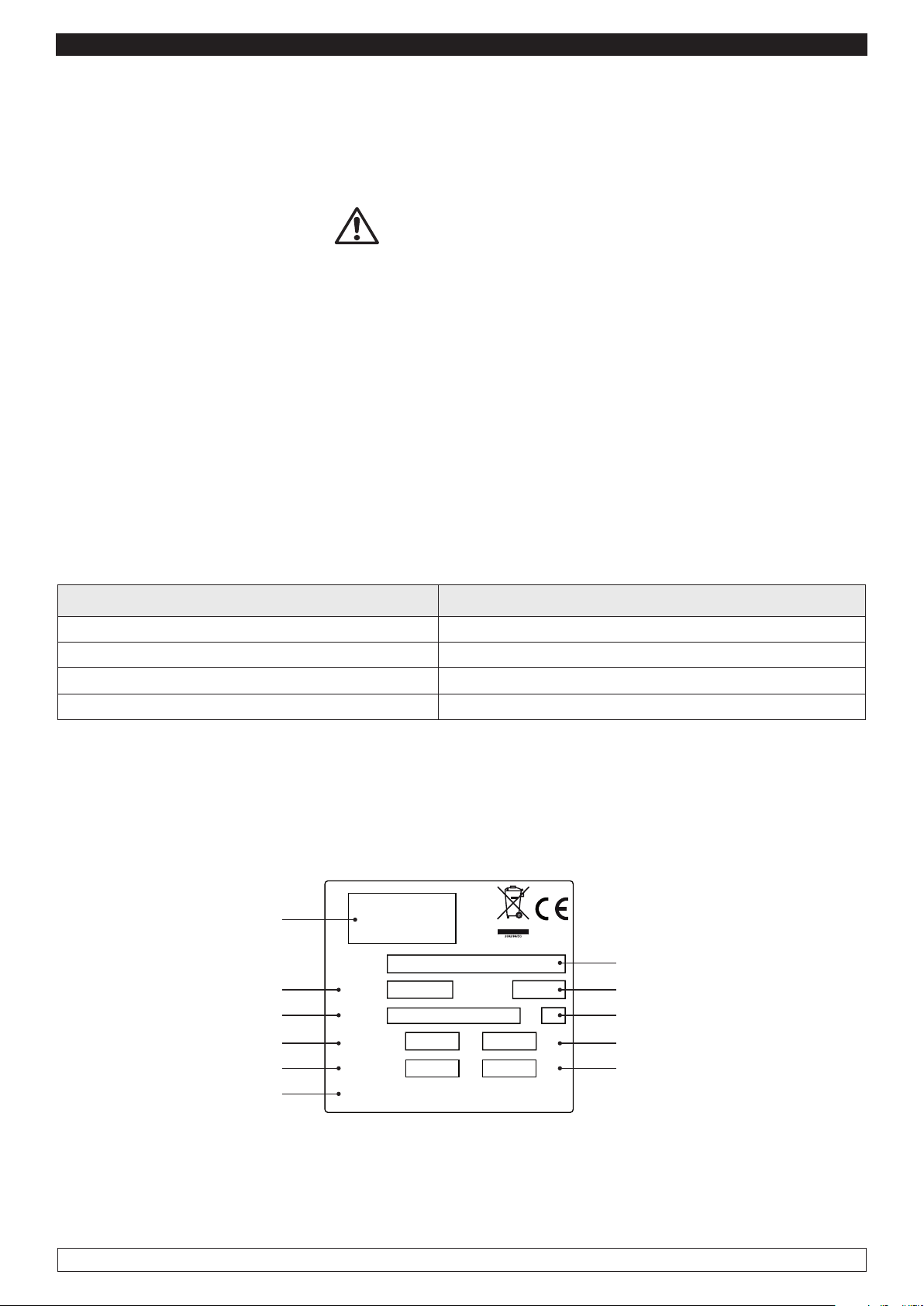
The data are reported on the EC label placed in the retarder-proofer/dough retarder refrigerated
cabinet and refrigerated table, inside the engine compartment.
Manufacturing Company
Code article
Operating voltage
Power consumption
Cooling capacity
Type of coolant
Modello
Model
Cod.Art
Code
Tensione
Tension
Assorbimento
Absorption
Gas
Gaz
IP20, CLASS 1
Matricola
Ser. Number
A
CL.
Kw
Kg
Model
Registration Number
Climate class
Electrical power
Quantity of coolant
The manufacturer declines any liability for improper use of the retarder-proofer/dough retarder
refrigerated cabinet and refrigerated table as well as use that could not have been reasonably
foreseen, and for all operations performed on it that disregard the instructions in the manual.
1
Page 3

ENGLISH
The main general safety standards are listed below:
- Do not use or place electrical devices inside the refrigerated compartments if they are not of the
type recommended by the manufacturer
- Do not touch the the retarder-proofer/dough retarder refrigerated cabinet and refrigerated table
with damp or wet hands or feet
- Do notuse the the retarder-proofer/dough retarder refrigerated cabinet and refrigerated table barefoot
- Do not insert screwdrivers or other objects between the guards or moving parts
- Do not pull the power cord to unplug the the retarder-proofer/dough retarder refrigerated cabinet
and refrigerated table from the electricity network
- The retarder-proofer/dough retarder refrigerated cabinet and refrigerated table are not intended to
be used by persons (including children) with physical or mental problems, or lack of experience and
knowledge, unless they are controlled or instructed in using the unit by a person responsible for their
safety. Children must be supervised to ensure that they do not play with the appliance.
- before carrying out any cleaning or maintenance, disconnect the refrigerated cabinet from the mains
power supply by turning off the main switch and pulling the plug
- in the event of failure and/or malfunction of the the retarder-proofer/dough retarder refrigerated
cabinet and refrigerated table, turn it off and to refrain from any attempt to repair or intervene directly.
It is necessary to exclusively contact a qualified technician.
The retarder-proofer/dough retarder refrigerated cabinet and refrigerated table are composed of a
modular monocoque coated with different materials and insulated with polyurethane foam of density
42 kg/m3.
In the design and construction, all measures have been adopted to ensure the retarder-proofer/dough
retarder refrigerated cabinet and refrigerated table comply with safety and hygiene requirements,
such as: rounded interior corners, deep drawing with drain on the outside for the condensate liquids,
no rough surfaces, fixed guards on moving or dangerous parts.
The products must be stored in observance of the load limits given in the table, in order to ensure
an efficient circulation of air inside the refrigerated cabinet.
Load limits expressed in Kg.
Grille 400x600 20
Sheet Metal Baking Trays 800x600 10
Sheet Metal Baking Trays 400x600 8
The installation must be performed exclusively by a qualified technician
1.1 It is prohibited to remove the guards and safety devices
It is absolutely forbidden to remove safety guards.
The manufacturer disclaims any liability for accidents due to failure to comply with this obligation.
1.2 Information on emergency operations in the event of fire
- disconnect the retarder-proofer/dough retarder refrigerated cabinet and refrigerated table from the
electrical outlet or cut off the main power supply
- do not use water jets
- use dry chemical or CO2 extinguishers
2
Page 4

ENGLISH
A
L
C
O
O
L
CHAPTER 2 CLEANING
Since the retarder-proofer/dough retarder refrigerated cabinet and refrigerated table will be used to
store food, cleaning is necessary for hygiene and health protection purposes.
The cleaning of the retarder-proofer/dough retarder refrigerated cabinet and refrigerated table have
already been carried out at the factory. It is suggested, however, to carry out an additional cleaning
of the internal parts before use, making sure that the power cord is unplugged.
2.1 Cleaning the interior and exterior cabinet
For this purpose the following are indicated
- the cleaning products: water and mild, non-abrasive detergents. DO NOT USE SOLVENTS AND
THINNERS
- methods for cleaning: wash the interior and exterior parts with warm water and mild soap or with a
cloth or sponge with suitable products
- disinfection: avoid substances that can alter the organoleptic characteristics of the food
- rinsing: cloth or sponge soaked in warm water. DO NOT USE WATER JETS
- frequency: weekly is recommended, the user can set different frequencies depending on the type
of food being stored.
REMARK : Clean frequently the door seals.
Some preserved products could release some enzymes that could damage
the seals causing its quick deterioration.
For the cleaning, use only specific products for this purposes, available also
on request on our sales network.
2.2 Cleaning the condenser
The efficiency of
the retarder-proofer/dough retarder refrigerated cabinet and refrigerated table
is
compromised by the clogging of the condenser, therefore it is necessary to clean it on a monthly basis.
Before carrying out this operation, switch off
and refrigerated table
unplug the power cord and proceed as follows:
Retarder-proofer/dough retarder refrigerated cabinet and refrigerated table
the retarder-proofer/dough retarder refrigerated cabinet
- open the front
control panel by unscrewing the screws and making it rotate on the hinges located below.
Retarder-proofer/dough retarder refrigerated cabinet and refrigerated table -
safe ladder and go directly to the condenser placed on top of
the retarder-proofer/dough retarder
climb up on a
refrigerated cabinet and refrigerated table
Fig.1
With the aid of a jet of air or dry brush, eliminate, in a vertical movement (Fig.
1), the dust and lint deposited on the fins. In the case of greasy deposits, we
recommend using a brush moistened with special cleaning agents.
When the operation is completed, restart
refrigerated cabinet and refrigerated table
the retarder-proofer/dough retarder
During this operation, use the following personal protective equipment: goggles, respiratory
protection mask, chemically resistant gloves (gasoline-alcohol).
3
Page 5

ENGLISH
CHAPTER 3 PERIODIC CHECKS TO BE CARRIED OUT
IMPORTANT: The following are the points or units of the retarder-proofer/dough retarder
refrigerated cabinet and refrigerated table that require periodic checks:
- integrity and efficiency of door seals
- integrity of the grilles in contact with food
- integrity of the fixing hinges of the doors
- integrity of the power cord
3.1 PRECAUTIONS IN CASE OF LONG PERIODS OF INACTIVITY
A long period of inactivity is defined as a stoppage of more than 15 days.
It is necessary to proceed as follows:
- switch off the retarder-proofer/dough retarder refrigerated cabinet and refrigerated table and
disconnect it from the power supply
- carry out a thorough cleaning of the interior cabinet, shelves, trays, guides and supports, paying
special attention to critical points such as the joints and magnetic gaskets, as indicated in Chapter 2.
- leave the door partly open to prevent air stagnation and residual humidity
CHAPTER 4 PREVENTIVE MAINTENANCE
4.1 Restarting after a long period of inactivity
Restarting after long inactivity is an event that requires preventive maintenance.
It is necessary to perform a thorough cleaning as described in chapter 2.
4.2 Control of the warning and control devices
We recommend that you contact your dealer for a service or maintenance contract that includes:
- cleaning of the condenser
- verification of the coolant load
- verification of the full cycle operation
- electrical safety
CHAPTER 5 EXTRAORDINARY MAINTENANCE AND REPAIR
All maintenance activities that have not been described in previous chapters are considered
“Extraordinary Maintenance.” Extraordinary maintenance and repair are tasks reserved exclusively
to the specialist personnel authorized by the manufacturer.
No liability is accepted for actions carried out by the user, by unauthorized personnel, or with the use
of non-original replacement parts.
4
Page 6

ENGLISH
CHAPTER 6 TROUBLESHOOTING
Problems may occur, in
the retarder-proofer/dough retarder refrigerated cabinet and refrigerated table
identified as shown in the table:
TROUBLE DESCRIPTION POSSIBLE CAUSES HOW TO REPAIR IT
the retarder-proofer/dough retarder
refrigerated cabinet and refrigerated
table do not turn on
the refrigeration unit does not start the set temperature has been reached set new temperature
the refrigeration unit runs continuously but does not reach the set
temperature
the refrigeration unit does not stop at
the set temperature
no power supply check the plug, socket, fuses, line
other fuses, line
defrosting in progress
control panel failed contact technical support
other contact technical support
location is too hot aerate more
condenser is dirty clean the condenser
insufficient coolant contact technical support
stop the condenser fan contact technical support
insufficient sealing of doors check the seals / provision of goods
evaporator completely frosted manual defrosting
other contact technical support
command panel failed contact technical support
Pr1 temperature sensor failed contact technical support
wait until the end of cycle / turn power off
and on again
misuse see chapter 1.
block of ice on the evaporator
accumulation of water or ice in the
drip tray
defrost heater fault contact technical support
defrost probe Pr2 damaged contact technical support
drain clogged clean the pipette and the drain
Cabinet/table are not levelled check levelling
CHAPTER 7 INSTRUCTIONS FOR REQUESTING ASSISTANCE
For any technical problem, and any requests for assistance or service, you must exclusively contact
your own dealer with the code and the registration number described on the label of technical data
applied on the equipment
CHAPTER 8 SAFETY AND ACCIDENT PREVENTION
The retarder-proofer/dough retarder refrigerated cabinet and refrigerated table have been built with
suitable measures to ensure the safety and health of the user.
The following are the measures taken to protect against mechanical risks:
- stability: The retarder-proofer/dough retarder refrigerated cabinet and refrigerated table , even with
the grilles removed, have been designed and built in such a way that under the intended operating
conditions, its stability is suitable for use without risk of overturning, falling or unexpected movement
- surfaces, edges, corners: the accessible parts of the retarder-proofer/dough retarder refrigerated
cabinet and refrigerated table are, within the limits allowed by their functions, free of sharp angles
and sharp edges, as well as rough surfaces likely to cause injury
- moving parts: were designed, constructed and arranged to avoid risks. Certain parts are equipped
with fixed guards so as to prevent risks of contact which may result in injury
5
Page 7
ENGLISH
2
The following are the measures taken to protect against other risks:
- electricity: The the retarder-proofer/dough retarder refrigerated cabinet and refrigerated table
have been designed, built and equipped so as to prevent risks from electricity, in accordance with
the specific legislation in force
- noise: The retarder-proofer/dough retarder refrigerated cabinet and refrigerated table have been
designed and built in such a way that risks resulting from the emission of airborne noise are reduced
to the minimum level
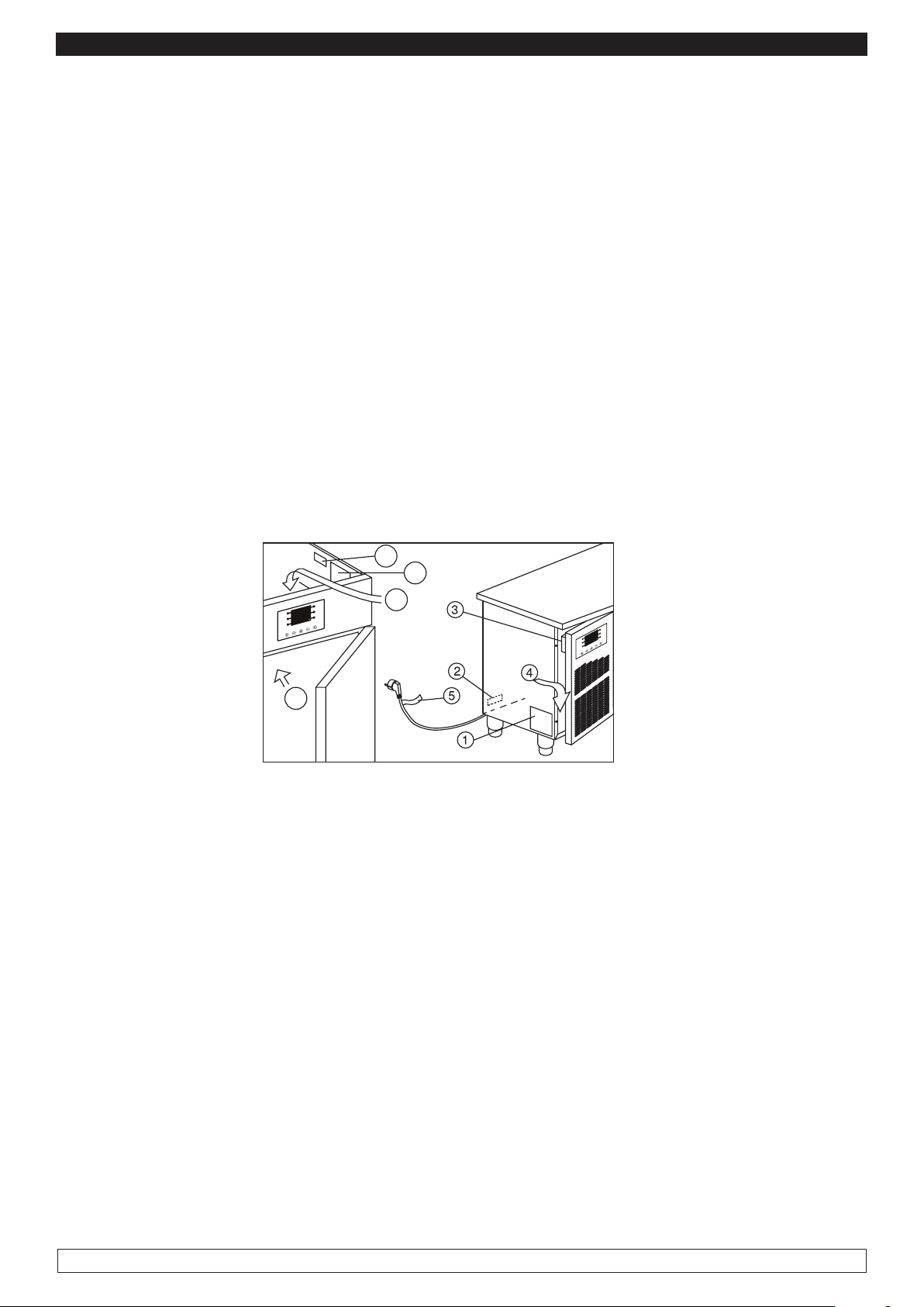
8.1 safety devices adopted (Fig. 2) :
- Do not remove the labels applied at the inner edge of the engine compartment, showing the technical
specifications (1) and the instructions for grounding (2)
- Do not remove the label applied on the evaporator guard and near the electrical wiring inside the
engine compartment, which warns the user to turn off the power supply before working on the unit (3)
- Do not remove the labels applied inside the engine compartment, indicating grounding (4)
- Do not remove the label applied on the power cord, indicating the type of power supply (5)
The manufacturer declines any responsibility for the safety of the the retarder-proofer/dough retarder
refrigerated cabinet and refrigerated table if this were to happen.
1
4
3
Fig.2
8.2 Indications for optimal operation
- do not block the air vents of the engine compartment
- do not insert foods or liquids that are still hot
- place the foodstuffs on the appropriate shelves or containers. Do not place them directly on the
bottom, or leaning against the walls, doors or fixed guards
- close the doors carefully
- always keep the defrost water drain hole clear of obstructions
- limit, to the extent possible, the frequency and duration of door opening. Each opening causes a
change in the internal temperature
- perform periodically current maintenance (see chapter 3)
In case of interruption or failure of the power supply circuit, prevent the opening of the doors in order
to maintain a uniform temperature inside the retarder-proofer/dough retarder refrigerated cabinet
and refrigerated table.
If the problem persists longer than a few hours it is recommended to move the material to a suitable
place.
6
Page 8

ENGLISH
USEFUL SUGGESTIONS
Before starting a RETARDER-PROOFING cycle it is advisable to pre-cool the empty cell at -5 ° C,
thus allowing more effective action of the Retarder-proofing action during the introduction of the
product (see par.10.6 p. 29)
For cycles longer than 48 H increase yeast of 0.5% speeding as possible the loading phase of the
product.
Do not bake the product once it has been taken out from the retarder proofer, leave at least 10
minutes at room temperature in order to avoid an excess of moisture in the surface that could cause
defects in the crust formation during cooking.
The possible bubbles formation on the bread is not synonymous of failure in the system, the cause
is almost always due to a problem of bread: dough too soft, too cold, low-quality flour, too much
moisture in the leavening phase, the oven is too hot, excess of cooking steam, etc
Avoid too high temperatures along with too short times during LEAVENING and PROVING, thermal
shock should cause problems to gluten and yeast damaging the quality of the finished product.
In the case of products that require periods of storage longer than 72H is advisable to use special
temperature blast chiller (see our catalogues) designed to bring the inside part of bread in the shortest
time to a temperature of -20 ° C thus allowing to keep the original organoleptic quality comparing it
to the fresh product.
Even the storage phase must take place in a special cold room who keeps constantly t -20 ° C.
PRELIMINARY NOTES
The control panel provides full control for retarder-proofer cabinets or tables for confectionery and
bakery, through the automatic management of the complete retarder-proofing cycle Example
START
MACHINE
COOLING
-5° / -10 °C
--- % r.H.
4-6 ore
STORAGE
-2° / +2 °C
--- % r.H.
changeable time
PROOFING
+10° / +13 °C
70 - 80 % r.H.
1 - 5 ore
LEAVENING
+25° / +30 °C
85 - 90 % r.H.
2 - 4 ore
END
CYCLE
STOP
MACHINE
DELAYED
BAKING
INF+25° / +30 °C
85 - 90 % r.H.
no limit of time
7
Page 9

ENGLISH
AUTOMATIC CYCLE
An automatic retarded proofing process consists of 5 steps providing different temperatures, relative
humidity, fans speed and different duration which are carried out in sequence as follows:
1. COOLING Phase
The block phase is the first phase of the automatic cycle.
► Temperature adjustment : ACTIVE AND ADJUSTABLE
► Duration (Hours/Minutes): ADJUSTABLE
► Fan speed : AUTOMATIC
2. PRESERVATION Phase
The preservation phase is the second phase of the automatic cycle.
► Temperature adjustement: ACTIVE AND ADJUSTABLE
► Duration : (Hours-Minutes): AUTOMATIC
► Fan speed : AUTOMATIC
The duration of this phase is automatically calculated by the controller on the basis of the duration
of the cooling , the proofing and the leavening processes as well as the day and the time the end of
the dough leavening process is required to stop.
3. PROOFING Phase
The proofing phase is the third phase of the automatic cycle.
►
Temperature adjustement : ACTIVE AND ADJUSTABLE
►
Humidity Adjustment : ACTIVE AND ADJUSTABLE
►
Duration (Hours-Minutes): ADJUSTABLE
►
Fan speed : AUTOMATIC
4. LEAVENING Phase
The leavening phase is the fourth phase of the automatic cycle.
►
Temperature adjustement : ACTIVE AND ADJUSTABLE
►
Humidity adjustment : ACTIVE AND ADJUSTABLE
►
Duration (Hours-Minutes): ADJUSTABLE
►
Fan speed : AUTOMATIC
5. DELAYED BAKING Phase
The delayed baking phase is the fifth phase of the automatic cycle.
The delayed baking phase may be either enabled or disabled both during the cycle setting and also
during a processing cycle by the final user.
► Temperature adjustment :ACTIVE AND ADJUSTABLE
► Humidity adjustement : ACTIVE AND ADJUSTABLE
► Fan speed : AUTOMATIC
► Duration (Hours-Minutes): The duration of this phase is virtually infinite , that is : it only stops when
you interrupt the cycle by pressing the stop button for 3 seconds.
MANUAL CYCLES
MANUAL COOLING PROCESS : (equivalent to storage but with infinite duration)
HEATING MANUAL PROCESS : (equivalent to a never-ending leavening process)
Besides the automatic and manual cycles management, the controller also provides you to control
other functions such as :
- Cell pre-cooling management system
- “Delayed baking” activation/deactivation management system
- 10 User’s Programmes management
- 10 Favourite Programmes management
- Connection to RICS (remote management – supervisory control) and RS485
- Onboard USB Host port management for PROGRAMMES download/upload , PARAMETERS
download/upload and HACCP data download.
8
Page 10
ENGLISH
6
9
10
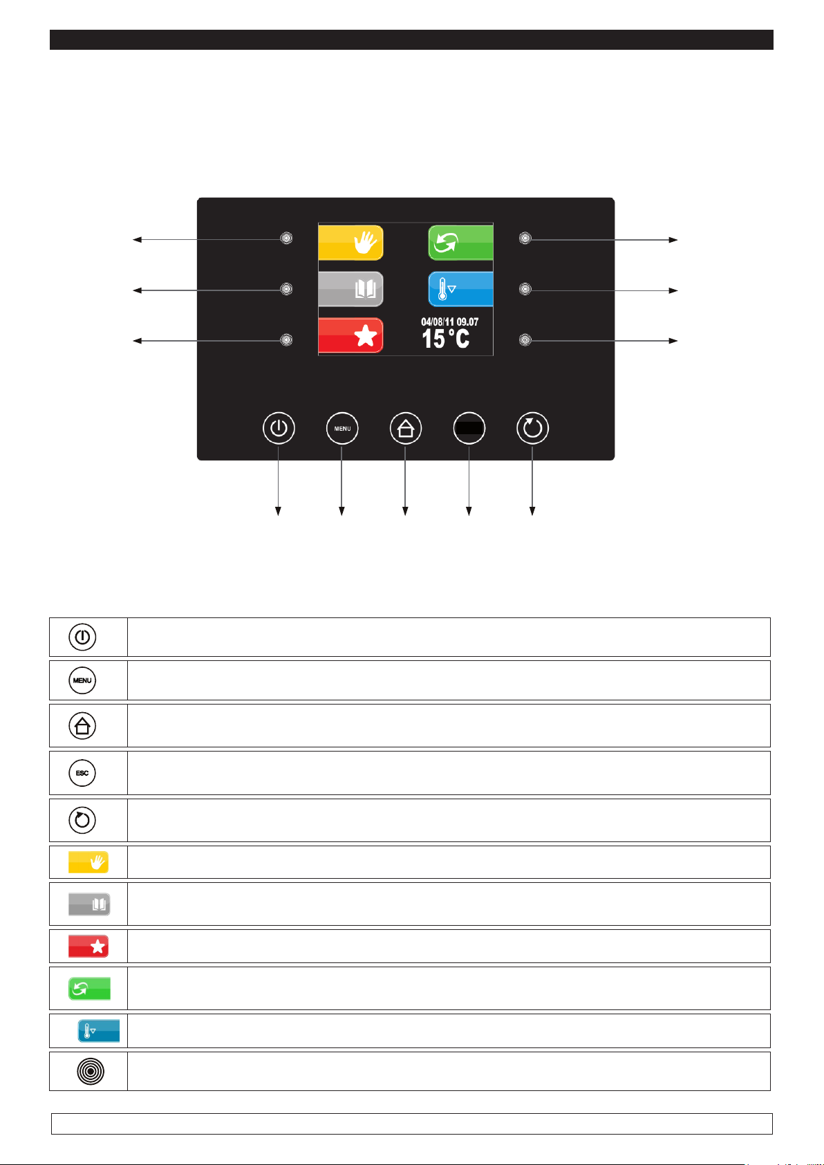
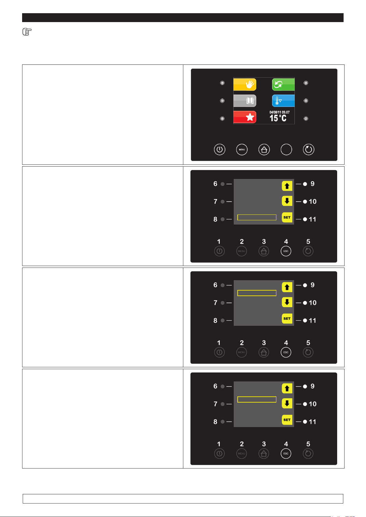
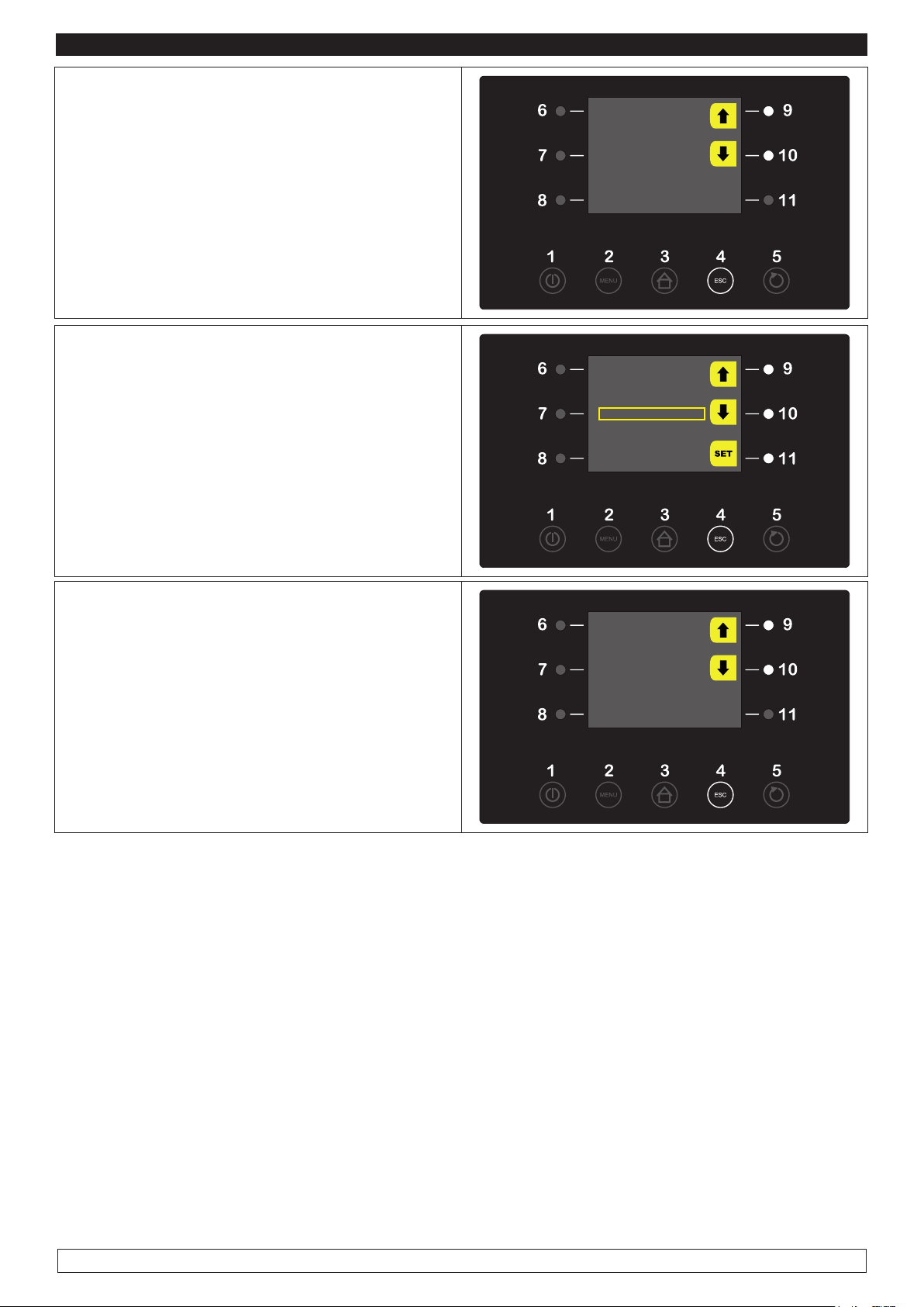
CHAPTER 9 CONTROLS
Description of control Panel:
The Control Panel consists of a digital capacitive-type temperature controller for coldness with colour
3,5” TFT supplied with user-friendly icons:
7
8
12345
The Control Panel is supplied with the following buttons:
1
2
3
ON / OFF It allows to change the controller’s status
MENU It allows to open the pop-up window containing the options for the current screen
HOME It allows to go back to the pre-selection screen at any time, cancelling any pro-
cessing selected programme.
11
ESC
4
5
6
7
8
9
10
11
ESC It allows to go back to the previous page at any time, cancelling any processing
selected programme.
START / STOP It allows to start/stop a working cycle, either manual or automatic or
auxiliary.
MANUAL KEY It allows to select a MANUAL working cycle
PROGRAMMES KEY It allows to select and/or change automatic retarded proofing
processes stored in memory.
FAVOURITE KEY It allows to recall the last 10 cycles performed promptly.
AUTOMATIC KEY It allows the selection, the setting and the implementation of a com-
plete automatic retarded proofing process.
PRE-COOLING KEY It allows the implementation of a cell pre-cooling cycle.
INTERACTIVE SELECTION KEY It allows to select the menu options
9
Page 11
ENGLISH
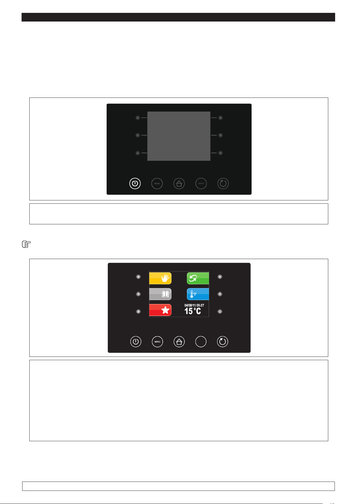
Active keys are the backlit keys only.
9.2 INSTRUCTIONS FOR USE
9.2.1 Starting process
Before starting the Retarder-Proofer Cabinet you need to check if the electrical connections have
been made according to what stated in Chapter 14.
LOADING...
► Connect the machine to the power supply: the display will switch on completely for 10’’, then
it shall be on the “STAND-BY” status.
Starting / switching-off : Start the panel by pressing the ON/OFF touch button (1)
1
ESC
► If the power cut has caused clock error , the display will directly show the clock setting
screen.
PLEASE NOTE:
the control panel shall not verify whether the inserted date is correct, it is up
to the user to set it properly. (Par. 9.2.2)
► While the machine is ON, the display will show the date, the present time, the cell temperature
and all the functions which may be selected.
- Press the ON / OFF key (1) to switch off.
10
Page 12

ENGLISH
9.2.2 Clock setting: set date and present time
The first operation to be carried out is setting the clock to the present time as follows:
► Press the MENU key (2) ,
2
ESC
► Select with the UP-DOWN keys (9-10) the
menu date and time options then confirm by
pressing the SET key (11)
OPTIONS
LIGHT
22/12/14 18:15
MANUAL DEFROST
ALARM LIST
INTERNAL VALUES
SERVICE
► Press the - and + keys (8-11) to adjust the date
then confirm by pressing the SET key (9)
► The adjustment of Month, Year , Hours and
Minutes will be automatically carried out in sequence.
► Press the - and + keys (8-11) to change the
inserted data.
► Press the SET key (9) to confirm the inserted
data.
22 / 12 / 14
18:15
22 / 12 / 14
18:15
►
When the operation is completed either press the ESC key (4) or do not work for 60 seconds.
11
Page 13
ENGLISH
9.2.3 Language setting
Proceed as follows:
► Press the MENU key (2),
► Select with the UP-DOWN keys (9-10) the
menu SERVICE item and press the SET key (11)
2
ESC
OPTIONS
LIGHT
22/12/14 18:15
MANUAL DEFROST
ALARM LIST
INTERNAL VALUES
SERVICE
► Select with the UP-DOWN keys (9-10) the
menu LANGUAGES item then press the SET
key (11)
►
Select with UP-DOWN keys (9-10) the desired
LANGUAGE
►
Press the SET key (11) to confirm
SERVICE
LANGUAGES
HISTORICAL DATA
INTERNAL SETTING
SERVICE
ITALIANO
ENGLISH
FRANCAIS
DEUTSCH
ESPANOL
►
When the operation is completed either press the ESC button (4) or do not work for 60 seconds.
12
Page 14
ENGLISH
CHAPTER 10 OPERATION
Main menu
In the pre-setting page there is the list of the available functions as well as the following data: date,
time and cell internal temperature.
ESC
The 5 “interactive” keys allow you to select:
MANUAL CYCLES: i.e. the selection, the setting-up and the implementation of a manual
cooling or heating cycle.
STORED PROGRAMMES: i.e. the selection and/or the adjustement of automatic retarded
proofing processes stored in memory.
FAVOURITE PROGRAMS: i.e. the prompt recalling of the last 10 performed cycles
AUTOMATICI CYCLES: i.e. the selection, the setting-up and the implementation of a complete
automatic retarded proofing process.
CELL PRE-COOLING PROGRAMME: i.e. The implementation of the cell pre-cooling cycle.
The 5 “Navigate” keys allow you to scroll to the desired menu and to activate the different working
cycles:
ON/OFF
MENU
HOME
ESC
START/STOP
13
Page 15
ENGLISH
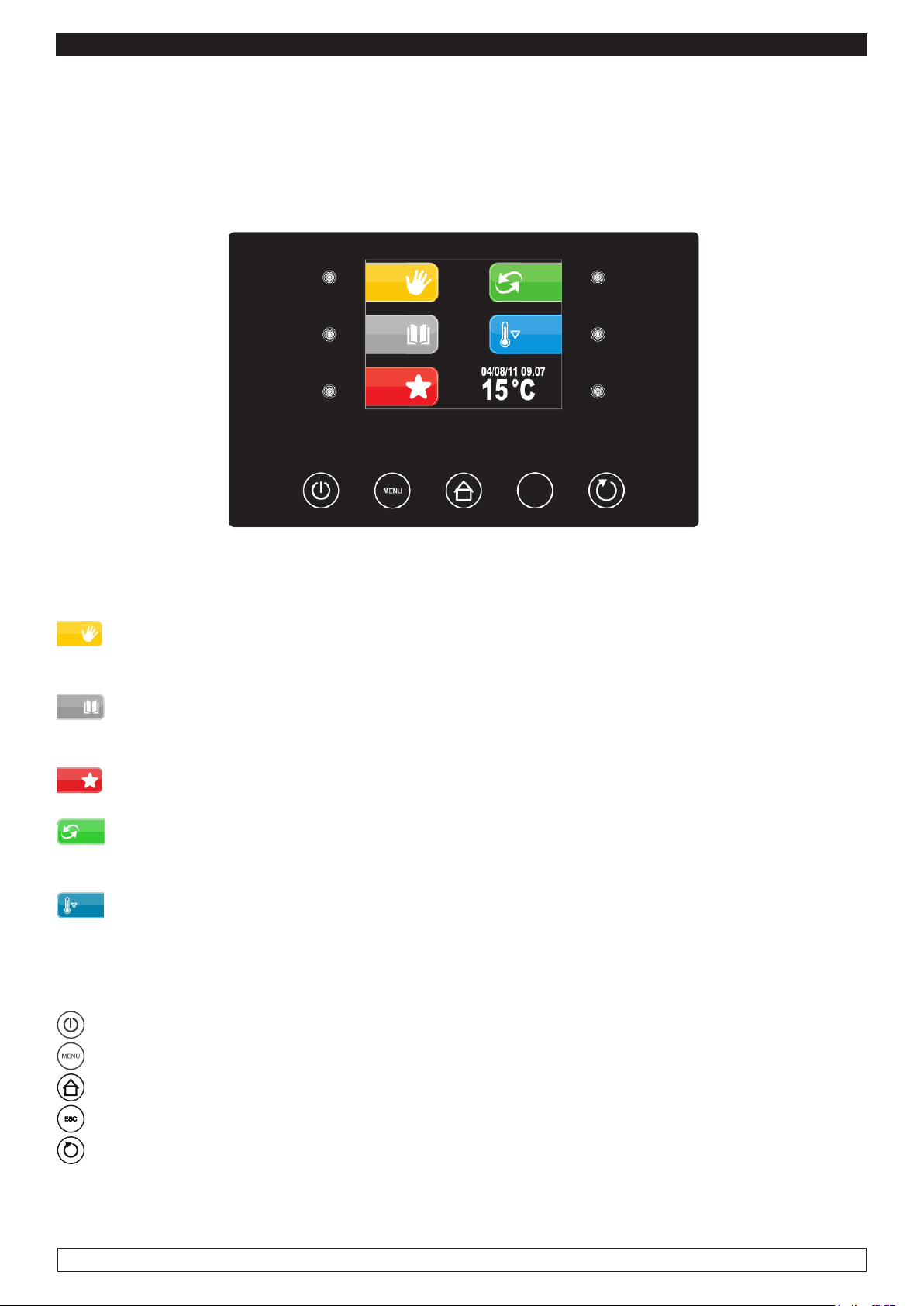
10.1 Setting-up and implementation of a MANUAL COOLING or HEATING cycle
From this menu you may select all the phases needed to carry out a manual COOLING or HEATING
cycle.
10.2 Setting up and running a cycle REFRIGERATION MANUAL:
► Press key MANUAL (6)
6
► Press one of the three left keys (6-7-8) to per-
form the MANUAL COOLING cycle
► Press the - and + keys (8-11) to adjust the CO-
OLING temperature
► Press the START/STOP key (5) to start the MA-
NUAL COOLING cycle
PLEASE NOTE: The fans speed adjustment function is disabled as it is automatically set.
Refrigeration Heating
12 °C
100%
14
Page 16
ENGLISH
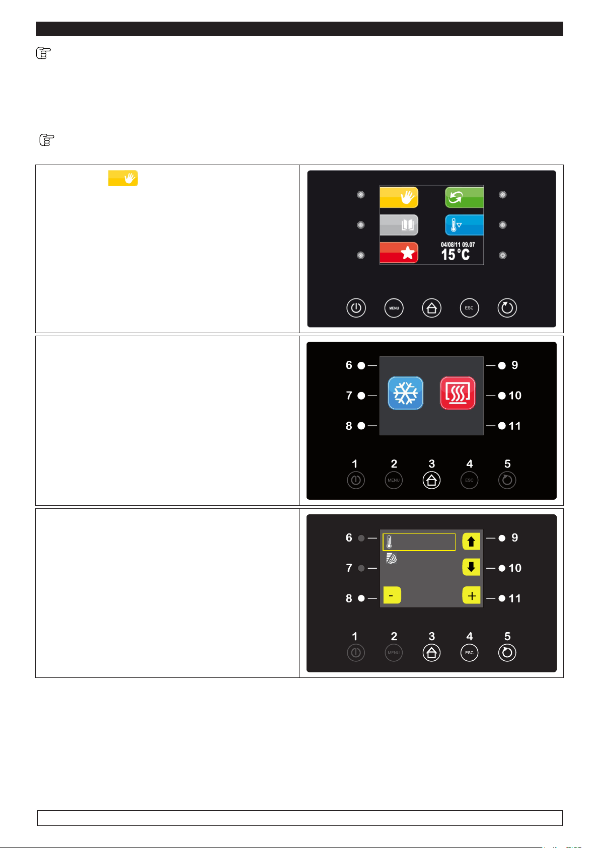
You may view the following list of OPTIONS by pressing the MENU key (2) during a MANUAL
COOLING cycle:
- SETPOINT
- ALARMS LIST
- INTERNAL VALUES
- MANUAL DEFROSTING (not to be carried out if not necessary)
- LIGHT
► To visualize the defined SETPOINT during a
working MANUAL COOLING cycle, press the
MENU key (2), select with the UP-DOWN keys
(9-10) the SETPOINT function and press the SET
key (11)
OPTIONS
SETPOINT
ALARM LIST
INTERNAL VALUES
MANUAL DEFROST
LIGHT
15:14 07/01/15
► To modify the defined SETPOINT press the -
and + keys (8-11)
► When the operation is over either press the ESC
button (4) to go back to the OPTIONS menu
PLEASE NOTE: The fans speed adjustment function is disabled as it is automatically set.
►
To display the ALARMS LIST during a working
MANUAL COOLING cycle, press the MENU key (2)
►Select with the UP-DOWN keys (9-10) the
ALARMS LIST item and press the SET key (11)
12 °C
100%
OPTIONS
SETPOINT
ALARM LIST
INTERNAL VALUES
MANUAL DEFROST
LIGHT
15:14 07/01/15
15
Page 17
ENGLISH
►The screen will display the current alarms list
► Press the UP-DOWN keys (9-10) to scroll throu-
gh the alarms, if the alarm is ON it is active, if it is
OFF it is not active.
► When the operation is over either press the ESC
key (4) to go back to the OPTIONS
► To view the INTERNAL VALUES during a wor-
king MANUAL COOLING cycle press the MENU
key (2)
► Press the UP-DOWN keys (9-10) to select the
INTERNAL VALUES then press the SET key (11)
ALARM LIST
Error Pr1 OFF
Error Pr2 OFF
Error Pr3 OFF
Error Pr4 OFF
Error AH OFF
Error PD OFF
OPTIONS
SETPOINT
ALARM LIST
INTERNAL VALUES
MANUAL DEFROST
LIGHT
15:14 07/01/15
► The screen will display the INTERNAL VALUES list.
► Press the UP-DOWN keys (9-10) to scroll throu-
gh the INTERNAL VALUES
► When the operation is over either press the ESC
INTERNAL VALUES
Temp cell 15°C
Humidity 40%
Temp Evap 27°C
Temp Cond - - -
Door OFF
High Pres OFF
key (4) to go back to the OPTIONS menu
PLEASE NOTE: The MANUAL DEFROSTING menu is activated only if the evaporator
temperature is lower than the final defrost end temperature.
To cancel the MANUAL COOLING cycle press the START/STOP button (5) for two consecutive
times. The display will go back to the Home screen.
16
Page 18

ENGLISH
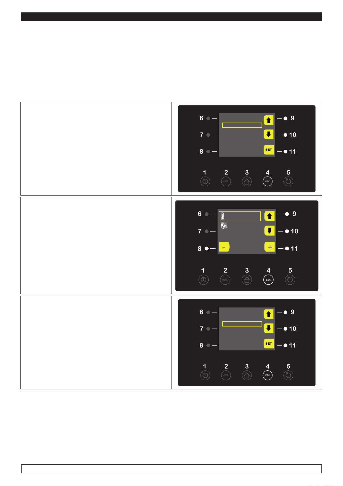
10.3 Setting-up and implementation of a MANUAL HEATING cycle:
► Press Key MANUAL (6)
6
► Press one of the three right keys (9-10-11) to
execute a MANUAL HEATING cycle
► Press the UP-DOWN keys (9-10) and select
the TEMPERATURE parameters. Press the and + keys (8-11) to modify its value
► Press the UP-DOWN keys (9-10) and select
the HUMIDITY parameters . Press the - and +
keys (8-11) to modify its value
► Press the START/STOP key (5) to start a MA-
NUAL HEATING cycle
PLEASE NOTE: The fans speed adjustment function is disabled as it is automatically set.
Refrigeration Heating
25 °C
80 %rH
100 %
► Once the MANUAL HEATING cycle is working,
the following screen shall be displayed.
Heating
26 °C
39 %rH
17
Page 19

ENGLISH
► You may view the following list of OPTIONS by pressing the MENU key (2) during a MANUAL HE-
ATING cycle:
- SETPOINT
- ALARMS LIST
- INTERNAL VALUES
- LIGHT
► Press the MENU key (2) to display the
SETPOINT during a working MANUAL HEATING
cycle.
► Select with the UP-DOWN keys (9-10) the
SETPOINT function then press the SET key (11)
OPTIONS
SETPOINT
ALARM LIST
INTERNAL VALUES
LIGHT
► To modify the defined TEMPERATURE value
press the – and + keys (8-11)
► Press the UP-DOWN keys (9-10) and select the
HUMIDITY parameters. Press the - and + keys
(8-11) to modify its value.
► When the operation is over either press the
ESC button (4) to go back to the OPTIONS menu
PLEASE NOTE: The fans speed adjustment function is disabled during all the process steps as it
is automatically set.
► To display the ALARMS LIST during a working
MANUAL HEATING cycle press the MENU key
(2).
► Select with the UP-DOWN keys (9-10) the
ALARMS LIST item then press the SET key (11).
25 °C
80 %rH
100 %
OPTIONS
SETPOINT
ALARM LIST
INTERNAL VALUES
LIGHT
18
Page 20

ENGLISH
► The display will show the current alarms list
► Press the UP-DOWN keys (9-10) to scroll throu-
gh the alarms list, if an alarm is ON it is active.
► When the operation is over either press the ESC
key (4) to go back to the OPTIONS menu
► Press the MENU key (2) to display the INTER-
NAL VALUES during a working MANUAL HEATING cycle.
► Press the UP-DOWN keys (9-10) to select the
INTERNAL VALUES then press the SET key (11)
ALARM LIST
Error Pr1 OFF
Error Pr2 OFF
Error Pr3 OFF
Error Pr4 OFF
Error AH OFF
Error PD OFF
OPTIONS
SETPOINT
ALARM LIST
INTERNAL VALUES
LIGHT
► The screen will display the list of INTERNAL VALUES
► Press the UP-DOWN keys (9-10) to scroll throu-
gh the INTERNAL VALUES, the temperatures
and the relays status for the unit running will be
displayed. Such values cannot be modified.
► When the operation is over either press the
INTERNAL VALUES
Temp cell 15°C
Humidity 40%
Temp Evap 27°C
Temp Cond - - -
Door OFF
High Pres OFF
ESC key (4) to go back to the OPTIONS menu or
do not work for 60 seconds.
To cancel a MANUAL HEATING cycle press the START/STOP button (5) for two consecutive
times. The display will go back to the Home screen.
19
Page 21

ENGLISH
10.4 Setting-up and implementation of an AUTOMATIC cycle :
The selection of the AUTOMATIC menu allows you to set up a complete retarded proofing process.
► Press key AUTOMATIC (9)
9
► Press the + button or the minus button to set
the end of cycle time
► Press SET (9) to confirm the hour and move
to change minutes after modification
► push the key SET (9) again to confirm the
time of the end of the cycle and move to the
next screen
The screen shows the day and time for end of
stroke and four selection options
-Hourly (7) time slot +24 +48 +72
-Clock (10)
-Pencil (8)
-Save data (11)
END CYCLE TIME CHANGE
END CYCLE
MON 30/12/13 12:00
Hourly -time slot (7) +24 +48 +72 by pushing
it delays the end time 24h 48h 72h cycle or
leaving unchanged the end time cycle and the
fermolievitazione program:
-Watch (10) Pushing it back to set the time for
the end of cycle
END CYCLE
MON 30/12/13 12:00
20
Page 22

ENGLISH
► Press key (8) to set up the AUTOMATIC
starting cycle parameters.
► Press the SET key (10) to modify the parame-
ters relative to the first “BLOCK” phase of the
automatic RETARDED PROOFING CYCLE.
- Temperature
- Duration
PHASE 1
-5 °C
04:32 h:m
100 %
PHASE 1
-5 °C
04:32 h:m
100 %
PLEASE NOTE: The fans speed adjustment fun-
ction is disabled as it is automatically set.
► Press the - and + keys (8-11) to modify the values
► Press the SET key (10) to confirm
► When the operation is over press the UP key
(9) to proceed to the next step
►
Press the SET key (10) to modify the parameters
relative to the second “PRESERVATION” phase of
the automatic RETARDED PROOFING cycle.
- Temperature
PHASE 1
-5 °C
04:32 h:m
100 %
PHASE 2
-5 °C
100 %
► Press the – and + keys (8-11) to modify the
TEMPERATURE values
► Press the SET key (10) to confirm
► When the operation is over press the UP key
(9) to proceed to the next step
PLEASE NOTE: The fans speed adjustment
function is disabled as it is automatically set
21
Page 23

ENGLISH
► Press the SET key (10) to modify the parame-
ters relative to the third “PROOFING” phase of
the automatic RETARDED PROOFING cycle.
- Temperature
- Humidity
- Duration
► Press the - and + keys (8-11) to modify values
► Press the SET key (10) to confirm
► When the operation is over press the UP key
(9) to proceed to the next step
PLEASE NOTE: The fans speed adjustment
function is disabled as it is automatically set .
► Press the SET key (10) to modify the parame-
ters relative to the fourth “LEAVENING” phase
of the automatic RETARDED PROOFING cycle.
- Temperature
- Humidity
- Duration
PHASE 3
3 °C
100 %
02:00 h:m
100 %
PHASE 4
28 °C
100 %
02:00 h:m
100 %
► Press the – and + keys (8-11) to modify values
► Press the SET keys (10) to confirm
► When the operation is over press the UP key
(9) to proceed to the next step
PLEASE NOTE: The fans speed adjustment
function is disabled as it is automatically set.
PLEASE NOTE : to skip one or more single step you should set its duration at 00:00 h:m
► Press the SET key (10) to modify the para-
meters relative to the fifth “DELAYED BAKING”
phase of the automatic RETARDED PROOFING
cycle.
- Delay baking
PHASE 5
SI
13 °C
85 % rH
100 %
- Temperature
- Humidity
► Press the – and + keys (8-11) to modify values
► Press the SET button (10) to confirm
PLEASE NOTE: The fans speed adjustment
function is disabled as it is automatically set.
► When all the programming phases of the AUTOMATIC CYCLE have been completed, press the
UP key (9) to review the set values of the different cycle steps.
22
Page 24

ENGLISH
► To save the new set cycle press the ESC key (4)
► Press the SAVE DATA button (11)
► Press the DOWN key (9) to save the program-
me with a name already existing in the list then
press the SAVE key (10) or save the programme
with a new name by pressing the SAVE AS key
(11)
END CYCLE
MON 30/12/13 12:00
PROGRAMS
P01 BREAD 100G
P02 BREAD 300G
P03 BREAD 500G
P04 <free>
P05 <free>
P06 <free>
P07 <free>
To save the programme with a new name:
BREAD 100G------
► Press the direction keys (6-7-9-10) to select
the letters
► Press the SET key (11) to confirm
► Press the DEL key (8) to cancel
► Select END to confirm and save the name of
A B C D E F G H I J K
M N O P Q R S T U V
Y Z 0 1 2 3 4 5 6 7 8 9
. , ; : ! ? % / * - + (
) ‘ (SPACE) (END)
the programme
Each recalled cycle always suggests the time with which the program has been saved
► Press the START/STOP keys (5) to view the
schedules of the end phase
► Press the START/STOP keys (5) again to start
the automatic cycle
END OF PHASES TIME
Phase 1 THU 08/01/15 h 13:47
Phase 1 THU 08/01/15 h 13:47
Phase 1 THU 08/01/15 h 13:47
Phase 1 THU 08/01/15 h 13:47
23
Page 25

ENGLISH
► The display will show the status of the current
PHASE, the end-of-cycle date and the temperature.
END CYCLE THU 08/01 17:47
► To deactivate the DELAYED BAKING phase
press the (8) key
PHASE 1
25 °C
At the end of the program the machine stops automatically in STAND-BY
During the implementation of an AUTOMATIC CYCLE press the MENU key (2) to view the following
options:
- SETPOINT
- ALARMS LIST
- INTERNAL VALUES
- END-OF-PHASE TIME
- MANUAL DEFROSTING
- LIGHT
► Press the MENU key (2) to modify the
SETPOINT during a working AUTOMATIC
CYCLE and select with the UP-DOWN keys (9-
10) the SETPOINT item then press the SET key
(11)
OPTIONS
SETPOINT
ALARM LIST
INTERNAL VALUES
END OF PHASES TIME
MANUAL DEFROST
LIGHT
15:14 07/01/15
► Press the – and + keys (8-11) to modify the de-
fined SETPOINT
► Press the 9 button to move to the next phase
► When the operation is over either press the ESC
key (4) to go back to the OPTIONS menu
PLEASE NOTE: The fans speed adjustment functon is disabled as it is automatically set.
24
PHASE 1
-5 °C
04:32 h:m
100 %
Page 26

ENGLISH
► Press the MENU key (2) to view the ALARMS
LIST during a working AUTOMATIC CYCLE.
► Select with the UP-DOWN keys (9-10) the
ALARMS LIST item then press the SET key (11)
► The display will show the alarms list (active
alarms are identied with ON)
► Press the UP-DOWN keys (9-10) to scroll throu-
gh the alarms
► When the operation is over either press the
ESC key (4) to go back to the OPTIONS menu or
do not work for 60 seconds.
OPTIONS
SETPOINT
ALARM LIST
INTERNAL VALUES
END OF PHASES TIME
MANUAL DEFROST
LIGHT
15:14 07/01/15
ALARM LIST
Error Pr1 OFF
Error Pr2 OFF
Error Pr3 OFF
Error Pr4 OFF
Error AH OFF
Error PD OFF
► Press the MENU key (2) to display the INTER-
NAL VALUES during a running AUTOMATIC
CYCLE
► Press the UP-DOWN keys (9-10) to select the
INTERNAL VALUES then press the SET key (11)
► The display will show the list of the INTERNAL
VALUES
► Press the UP-DOWN keys (9-10) to scroll down
the INTERNAL VALUES
► When the operation is over either press the
ESC key (4) to go back to the OPTIONS menu or
do not work for 60 seconds.
OPTIONS
SETPOINT
ALARM LIST
INTERNAL VALUES
END OF PHASES TIME
MANUAL DEFROST
LIGHT
15:14 07/01/15
INTERNAL VALUES
Temp cell 15°C
Humidity 40%
Temp Evap 27°C
Temp Cond - - -
Door OFF
High Pres OFF
25
Page 27

ENGLISH
► Press the MENU key (2) to view the END-OF-
PHASES TIME during a running AUTOMATIC
CYCLE.
► Press the UP-DOWN keys (9-10) to select the
END-OF-PHASES TIME then press the SET key
(11)
► The display will show the list of the END-OF-
PHASES TIME
OPTIONS
SETPOINT
ALARM LIST
INTERNAL VALUES
END OF PHASES TIME
MANUAL DEFROST
LIGHT
15:14 07/01/15
END OF PHASES TIME
► When the operation is over either press the
ESC key (4) to go back to the OPTIONS menu or
Phase 1 THU 08/01/15 h 13:47
Phase 1 THU 08/01/15 h 13:47
Phase 1 THU 08/01/15 h 13:47
Phase 1 THU 08/01/15 h 13:47
do not work for 60 seconds.
To cancel the AUTOMATIC cycle press the START/STOP button (5) for two consecutive
times. The display will go back to the Home screen.
26
Page 28

ENGLISH
10.5 PROGRAMS:
The PROGRAMS menu allows you to select a retarded proong cycle among the 10 available
programme locations.
► Press key PROGRAMS (7)
7
► Press the UP-DOWN keys (9-10) to scroll down
the list
► Press the SET key (11) to select the desired
program.
► Press the START/STOP key (5) to start the se-
lected program or
PROGRAMS
P01 BREAD 100G
P02 BREAD 300G
P03 BREAD 500G
P04 <free>
P05 <free>
P06 <free>
P07 <free>
► Press the CHANGE VALUES key (8) to modify
the SETs of the different phases (see Par. 10.4
page 20)
The screen shows the day and time for end of
stroke and four selection options
-Hourly (7) time slot +24 +48 +72
-Clock (10)
-Pencil (8)
-Save data (11)
► Press the START/STOP key (5) twice to start
the selected program
► The display will show the current status of the
running PHASE , the current end-of-cycle date
and the temperature.
► Press the (8) key to deactivate the DELAYED
BAKING phase. The same options of the AUTOMATIC CYCLE will be available by pressing
the MENU key (2) during the running of a PROGRAM (Chapter10.4 page 20)
END CYCLE
MON 30/12/13 12:00
END CYCLE THU 08/01 17:47
PHASE 1
25 °C
27
Page 29

ENGLISH
► Retarded proong process already stored
As an example it has been stored 3 programs : Bread 100 gr., Bread 300 gr., Bread 500 gr.
P01 - Bread 100 gr.
PHASE 1 PHASE 2 PHASE 3 PHASE 4 PHASE 5
COOLING STORAGE PROOFING LEAVENING DELAYED BAKING
Temperature -5 2 16 28 22
Humidity NOT ACTIVATED NOT ACTIVATED 80% 80% 75%
Time 03:30 (hh:mm) AUTOMATIC 03:00 (hh:mm) 2:00 (hh:mm) INFINITE
Fan speed 100% 100% 100% 100% 100%
P02 - Bread 300 gr.
PHASE 1 PHASE 2 PHASE 3 PHASE 4 PHASE 5
COOLING STORAGE PROOFING LEAVENING DELAYED BAKING
Temperature -5 0 16 28 22
Humidity NOT ACTIVATED NOT ACTIVATED 80% 80% 75%
Time 04:00 (hh:mm) AUTOMATIC 03:30 (hh:mm) 02:30 (hh:mm) INFINITE
Fan speed 100% 100% 100% 100% 100%
P03 - Bread 500 gr.
PHASE 1 PHASE 2 PHASE 3 PHASE 4 PHASE 5
COOLING STORAGE PROOFING LEAVENING DELAYED BAKING
Temperature -6 -2 16 28 22
Humidity NOT ACTIVATED NOT ACTIVATED 80% 80% 75%
Time 04:30 (hh:mm) AUTOMATIC 04:00 (hh:mm) 03:00 (hh:mm) INFINITE
Fan speed 100% 100% 100% 100% 100%
The remaining 7 positions, on 10 available are personalised directly by the customer himself.
28
Page 30

ENGLISH
10.6 PRE-COOLING CYCLE:
The purpose of the pre-cooling cycle is to lead the cell to a defined temperature before selecting and
starting a retarded proofing cycle.
Once the pre-cooling temperature is reached , the buzzer sounds in an intermittent manner indicating
that the machine is ready to perform a cycle.
The pre-cooling cycle goes on running until the START/STOP key is pressed or up to the starting of
an automatic or manual cycle.
► Press key PRE-COOLING (10)
10
► Press the - and + keys (8-11) to modify the
temperature
► Press the START/STOP key (5) to start the
PRE-COOLING cycle
► The display will show a flashing white triangle
on the PRE-COOLING icon (10)
The cycle may last until you start a program. When
the defined temperature is reached an acoustic signal will sound.
► To cancel the PRE-COOLING cycle hold the
START/STOP key (5) pressed for more than 5 seconds.
Pre-cooling
-5 °C
Start
10
5
29
Page 31

ENGLISH
10.7 FAVOURITE RUNNING CYCLES :
This menu allows you to recall the favourite running cycles promptly, i.e. the last 10 implemented
cycles.
► Press key FAVOURITES (8)
8
► Press the UP-DOWN keys (9-10) to scroll down
the list of favourite programs
► Press the SET key (11) to select a favourite
program
FAVOURITES
F01 BREAD 100GM
F03 ---
F04 ---
F05 ---
F06 ---
F07 ---
F08 --
► If necessary, press the CHANGE VALUES key
(8) to modify the SETs of the different phases (see
Par. 10.4 page 20)
END CYCLE
MON 30/12/13 12:00
The screen shows the day and time for end of
stroke and four selection options
-Hourly (7) time slot +24 +48 +72
-Clock (10)
-Pencil (8)
-Save data (11)
► Press the START/STOP key (5) twice to start
the selected program.
The management of the cycle will be the same as
the setting of an automatic cycle
To cancel the cycle hold the START/STOP button (5) for two consecutive times.. The display
will go back to the Home screen.
30
Page 32

ENGLISH
10.8 ALARMS
This page allows you to enter the ALARMS menu .
► Premere key MENU (2),
► Select with UP-DOWN keys (9-10) ALARMS
LIST item then press the SET key (11)
2
OPTIONS
LIGHT
22/12/14 18:15
MANUAL DEFROST
ALARM LIST
INTERNAL VALUES
SERVICE
► Press the UP-DOWN keys (9-10) to scroll
through the alarms list .
Active alarms will be identified with ON
► Either press the ESC key (4) to terminate or do
not work for 60 seconds.
ALARM LIST
Error Pr1 OFF
Error Pr2 OFF
Error Pr3 OFF
Error Pr4 OFF
Error AH OFF
Error PD OFF
Error CSd OFF
31
Page 33

List of alarms which may occur:
ENGLISH
ALARM
Pr1 Cell probe error • Cell probe fails • Replace probe
Pr2 Evaporator probe error • Evaporator probe fails • Replace probe
Pr3 Condenser probe error • Disabled • Disabled
Pr4 Humidity probe error • Humidity probe is faulty • Replace the probe
AH
PD
CSd Blocked Compressor alarm • Disabled • Disabled
COH Blocked Compressor alarm • Disabled • Disabled
rtc Internal clock error
Maximum temperature
alarm
Poup-Down
compressor alarm
DESCRIPTION CAUSE SOLUTION
• Cell probe is faulty
• Control unit is faulty
• Cooling system is faulty
• Disabled • Disabled
• The device has not worked
for a long period
• Control unit is faulty
• Service
• Service
• Service
• Switch on the device
and set the date again
• Service
CtH
ErC
ErL
PF
id Open door alarm
HP High pressure alarm • Disabled • Disabled
LP Low pressure alarm • Disabled • Disabled
Compressor thermal
protector
No compatibility between
interface and control modu-
No communication between
interface and control module
Interruption of power supply
to the machine
• Disabled • Disabled
• Firmware of setting - instrument
is not compatible
• Interface connection is either
incorrect or faulty
• Power failure may have
occurred
• The door has been kept open
• Service
• Check proper
connection
• Press any key to cancel
the alarm
• Close the door
32
Page 34

ENGLISH
10.9 MANUAL DEFROSTING
To start a MANUAL DEFROSTING cycle proceed as follows.
► Premere the key MENU (2),
► Select with the UP-DOWN keys (9-10) the MA-
NUAL DEFROSTING item then press the SET
key (11)
The defrosting cycle will start if the evaporator
temperature is lower than the defined value for
the defrosting completition, only
2
OPTIONS
LIGHT
22/12/14 18:15
MANUAL DEFROST
ALARM LIST
INTERNAL VALUES
SERVICE
► The display will go back to the Home screen
where the defrost icon relative to the MANUAL
DEFROSTING cycle running will appear in the
center of the picture display.
33
Page 35

ENGLISH
10.10 INTERNAL LIGHT SWITCHING-ON ( for cabinets supplied with glass door only)
To switch on the internal light proceed as follows.
► Press key MENU (2),
2
► Select with the UP-DOWN keys (9-10) the
LIGHT item then press the SET key (11)
The machine internal LIGHT will switch on.
Press the SET key (11) to switch off the light
OPTIONS
LIGHT
22/12/14 18:15
MANUAL DEFROST
ALARM LIST
INTERNAL VALUES
SERVICE
It is possible to switch on the internal LIGHT at any time even when the machine is running by
pressing the MENU key (2) and repeating the above procedure.
34
Page 36

ENGLISH
10.11 Detailed description of the icons relative to the Controllers Status
During the implementation of a cycle (either Manual or Automatic) the status of the main controllers
shall be displayed by means of icons.
► White ON : compressor is activated
► Yellow ON: compressor activation is required
► OFF : compressor is not active
► ON : heating is activated
► OFF: heating is not active
► ON : humidification is activated
► OFF : humidification is not active
► ON : dehumidification is activated
► OFF : dehumidificazione is not active
Buzzer silencing
Press and release any key when the buzzer is sounding.
Alarms
When an alarm signal occurs a pop-up window opens stating the current alarm code. The buzzer
sounds in an intermittent manner until you press any key silencing the buzzer and making the popup window disappear.
The icon indicating the current alarm is still present on the screen
35
Page 37

ENGLISH
10.12 USB Host Port
By inserting a USB stick you may have the possibility to carry out the following operations:
► Download the data relative to the cycles performed on the USB stick (historical records)
► Download the saved parameters onto the USB stick (service)
► Download the saved programs onto the USB stick (service)
► Upload the parameters contained in the USB stick (service)
► Upload the programs contained in the USB stick (service)
10.13 Download of data relative to the cycles performed on the USB stick (historical
records)
It allows to record the data relative to the performed cycles onto the USB stick and view them on
any PC by means of Excel computer program.
► If ON put the card in STAND-BY mode by
pressing the ON/OFF key (1)
► Insert the USB stick into the USB host port
► Select with the UP-DOWN keys (9-10) the
DOWNLOAD HISTORY menu then press the
SET key (11)
DOWNLOAD HISTORY
DOWNLOAD PARAMETERS
DOWNLOAD PROGRAMS
UPLOAD PARAMETERS
UPLOAD PROGRAMS
USB
► Select with the – and + keys (8-11) date and
time
► Press the SET key (9) to confirm
► Press the START/STOP key (5) to download
data relative to performed cycles onto the USB
stick.
► When the operation is over take out the USB
stick. This option saves a text file (CSV) onto the
USB stick that may be displayed on any type of
PC fitted with EXCEL program
SELECT
DATE AND TIME
09 / 01 / 15
13.44
USB
DOWNLOAD HYSTORY
END
REMOVE KEY
The download le will be a CSV format, i.e. it can be simply open with a double click by any computer
tted with Excel program.
36
Page 38

ENGLISH
The recorded les have a sequential number accordingly with the number of times they have been
unloaded.
In this way the name of le could change in “log00n00001.csv”, “log00n00002.csv”, etc.
All collected data will be automatically entered in tabular form on a Excel sheet, separated into
columns and rows. You can then obtain tables and graphs (see example) depending on your needs.
EVFTFT618
°C °C %
12/03/2015 14.00 Start 19 19 44
State cycle In progress
Type of cycle Manual
Number of phase Heating
Defrost cycle Off
Status compressor Off
State light Off
State humidier Off
State dehumidier Off
State defrosting Off
State desistance Off
State steam generator Off
12/03/2015 14.02 Event 20 20 44
High Press. alarm Present
12/03/2015 14.03 Event 20 20 44
High Press. alarm Not present
12/03/2015 14.05 sampling 20 20 44
12/03/2015 14.08 event 20 20 43
High Press. alarm Present
12/03/2015 14.08 event 20 20 43
High Press. alarm Not present
12/03/2015 14.09 Event 20 20 43
Thermal probe Present
12/03/2015 14.09 Event 20 20 43
Thermal probe Not present
12/03/2015 14.10 Sampling 20 20 42
12/03/2015 14.11 Stop 20 20 42
12/03/2015 14.11 Start 20 20 42
State cycle In progress
Type of cycle Automatic
Number of Phase Phase 1
12/03/2015 14.16 Sampling 21 21 43
12/03/2015 14.16 Stop 21 21 43
Cell
probe
Evaporator
probe
Umidity
probe
CHAPTER 10 NOISE LEVEL
The noise threshold of the retarder-proofer/dough retarder refrigerated cabinet and refrigerated
table is lower than 70 dB (A).
CHAPTER 11 MATERIALS AND FLUID USED
The materials in contact or which may come into contact with foodstuffs comply with the relevant
directives.
The retarder-proofer/dough retarder refrigerated cabinet and refrigerated table have been
designed and built in such a way that these materials can be cleaned before each use.
The coolants used R404A/R290 conform to the relevant provisions of law (see Table 1).
R404A is a fluorinated gas covered by the Kyoto Protocol with a GWP potential of 3300
The symbol indicates that this product must not be treated as household waste.
To prevent potential negative consequences for the environment and human health, make sure that
this product is properly disposed of and recycled.
For more information regarding the disposal and recycling of this product, please contact your
Distributor, after sale Service, or waste treatment Service.
37
Page 39

ENGLISH
CHAPTER 13 TRANSPORT AND HANDLING
The transport and handling of the retarder-proofer/dough retarder refrigerated cabinet and
refrigerated table must only be done while maintaining the vertical position, observing the markings
on the packaging.
The manufacturer disclaims any liability for problems resulting from transport performed
under conditions other than those specified above.
The accessories of the retarder-proofer/dough retarder refrigerated cabinet and refrigerated table
(guides, grilles, trays, remote condensing unit with pipes) are packaged separately and placed inside
the unit.
The retarder-proofer/dough retarder refrigerated cabinet and refrigerated table are mounted on a
wooden base with screws and packaged with polyethylene, carton, crate or boxes.
Regarding the disposal of the packaging it is necessary to refer to current regulations in your country.
The movement of the retarder-proofer/dough retarder refrigerated cabinet and refrigerated
table shall be performed using a fork lift or pallet trucks equipped with suitable forks (length of at
least 2/3 of the unit).
The dimensions and masses of the retarder-proofer/dough retarder refrigerated cabinet and refrigerated
table packed are shown in Table 1.
The limits of stackability and the centre of gravity are indicated on the label of the package.
13.1 Positioning operations
Since the incorrect positioning of the retarder-proofer/dough retarder refrigerated cabinet and
refrigerated table can cause damage to the same, jeopardizing its proper functioning and cause risks
to the personnel, the installer must comply with the following general rules:
- position the retarder-proofer/dough retarder refrigerated cabinet and refrigerated table keeping a
minimum distance of 3 cm from any wall
- the environment must be sufciently ventilated
- position the retarder-proofer/dough retarder refrigerated cabinet and refrigerated table away from
heat sources
- avoid exposure to direct sunlight
- remove the polyethylene, cardboard or wood packaging
38
Page 40

ENGLISH
Polyethylene is dangerous for children
- remove any accessories with external connections
Removing the wooden base (g. 4) : tilt the retarder-proofer/dough retarder refrigerated cabinet and
refrigerated table sideways and unscrew the two self-tapping screws (cabinet solely) , lift the retarderproofer/dough retarder refrigerated cabinet and refrigerated table and remove the base.
Fig.4
use protective gloves when handling the wooden packaging and the wooden base.
The presence of splinters may cause damage to your hands
- remove the PVC lm applied as a protection to the outer surfaces of he retarder-proofer/dough
retarder refrigerated cabinet and refrigerated table
- position the retarder-proofer/dough retarder refrigerated cabinet and refrigerated table using a level
with possible adjustment of the feet of the metal base (Fig. 5 )
Fig.5
- position the grille holding guide fails in the holes of the racks (Fig. 6 )
39
Fig.6
Page 41

ENGLISH
- insert the grilles for food in the special guides
- insert the condensate water drain pan into the special guide rails already xed under the retarder-
proofer/dough retarder table REM.
13.2 Retarder-proofer/dough retarder refrigerated cabinet and refrigerated table REM ( Fig. 7 )
Fig.7
- position the retarder-proofer/dough retarder table REM as described above (Fig. 5)
- prepare the two tubes that come out of the retarder-proofer/dough retarder table and cabinet REM
(refer to the technical sheet of the equipment) for the connection to the respective pipes
- connect the pipes of the condensing unit to the pipes of the retarder-proofer/dough retarder table
- create a vacuum and then carry out the loading of the coolant
- make the electrical connection of the retarder-proofer/dough retarder table and cabinet to the
condensing unit
- perform a functional test to verify the correct gas charge.
CHAPTER 14 ELECTRICAL WIRING AND CONNECTIONS
The electrical system and connection must be carried out by qualified personnel. Before installation,
measure the impedance of the network, the impedance value for the connection to the network must
not exceed 0.075 ohm.
For safety reasons you must follow these guidelines:
- verify that the sizing of the electrical system is suitable for the power consumption of the retarderproofer/dough retarder table and cabinet and that it provides for a differential switch (circuit breaker)
- in case of incompatibility between the outlet and the plug of the retarder-proofer/dough retarder
table and cabinet, replace the outlet with another of a suitable type provided that it is in accordance
with regulations
- do not insert adapters and/or reductions (Fig. 8)
Fig.8
The power cord has the connection type “Y” and it can be replaced exclusively by the
manufacturer or authorized technical service
40
Page 42

ENGLISH
It is essential to correctly connect the retarder-proofer/dough retarder table and cabinet to an
efcient earthing system carried out as specied by the applicable provisions of law.
14.1 Connection to the water supply (retarder-proofer solely)
All models of retarder-proofer/dough retarder refrigerated table and refrigerated cabinet need to
be connected to a water supply to perform the functions of management and control of humidity.
The connection to water supply must be made according to the manufacturer’s instructions and by
professionally qualied personnel. The tting of 3/4 for the connection to the water supply is located
in the condensing unit of the retarder-proofer cabinets, in the rear, close to the housing of the power
supply cable at an height from the ground of cm 190. This unit must only be supplied with cold water,
not distilled or demineralized.
The operating pressure should be between 0.1 and 0.5 MPA. Between the water network and the
load connection of the equipment 3/4 should be installed a tap to interrupt the passage of water in
case of need. In the case the water is hard it is advisable to install a water softener, the presence of
solids such as sand can be eliminated by installing a mechanical lter to be inspected and cleaned
periodically.
CHAPTER 15 INSTALLATION OPERATIONS
It is important, in order to prevent errors and accidents, to perform a series of checks before starting
up the the retarder-proofer/dough retarder table and cabinet in order to identify any damage incurred
during transport, handling and connection.
Checks to be performed:
- check the integrity of the power cord (it must not have suffered abrasions or cuts)
- check the solidity of the legs, door hinges, shelf supports
- check the integrity of the internal and external parts (pipes, heating elements, fans, electrical
components, etc.) and their xing
- check that the seals of the doors and drawers have not been damaged (cuts or abrasions) and
close with an airtight seal
- check the integrity of the pipes and ttings (REM)
CHAPTER 16 REINSTALLATION
It is necessary to comply with the following procedure:
- disconnect the power cord from the power outlet
- the handling should be carried out as described in chapter 13
- for a new placement and connection, please refer to par. 13.1
- for the REM models proceed to the possible recovery of the coolant gas in accordance with the
regulations in force in your country
41
Page 43

ATTENTION!
INSTRUCTIONS RESERVED SOLELY TO TECHNICAL
PERSONNELL
Users are adviced that any work performed by non-technical staff or
unauthorized personnel will produce the voiding of the warranty rules.
42
Page 44

PARAMETER MODIFICATION DISPLAYING
It allows to access the setup parameters of the
Control Panel.
► Press the MENU key (2).
► Select with the UP-DOWN keys (9-10) the
“SERVICE” menu item then press the SET key
(11)
2
OPTIONS
22/12/14 18:15
MANUAL DEFROST
ALARM LIST
INTERNAL VALUES
SERVICE
► Select with the UP-DOWN keys (9-10) the
“INTERNAL SETUP” menu item then press the
SET key (11)
► Enter the Password* (-19) with the – and +
keys (8-11) then press the SET key (9)
SERVICE
LANGUAGES
HISTORICAL DATA
INTERNAL SETTING
PASSWORD
PA -19
43
Page 45

► Select with the UP-DOWN keys (9-10) the
menu item then press the – and + keys (8-11) to
modify values.
► Either press the ESC key (4) to exit or do not
work for 60 seconds.
ALARM LIST DISPLAYING
Proceed as stated at Paragraph 10.8 to display the alarms list.
PARAMETERS
CA1
CA2
CA3
CA4
P0
P2
1
0
0° C
0° C
0° C
%
44
Page 46

RETARDER PROOFER CABINETS/TABLES AND DOUGH-RETARDER PARAMETERS
Par. Min. Mas. Unit Dough
CA1 ¬25 25 °C 0 0
CA2 ¬25 25 °C 0 0
CA3 ¬25 25 °C 0 0
CA4 ¬25 25 %r.H. 0 0
P0 0 1 ¬¬¬¬ 1 1
P2 0 1 ¬¬¬¬ 0 0
P3 0 1 ¬¬¬¬ 1 1
P4 0 1 ¬¬¬¬ 0 0
P5 0 60 Min 60 60
P6 0 2 ¬¬¬¬ 1 1
P7 0 P8 %r.H. 0 0
P8 P7 100 %r.H. 100 100
P9 0 250 ds 5 5
Par. Min. Mas. Unit Dough
rC0 1 15 °C 2 2
rC1 ¬99 rC2 °C ¬-10 -10
rC2 rC2 99 °C 20 20
rC3 0 10 °C 1 1
rC4 0 10 °C 1 1
rC5 0 10 °C 1 1
rC6 ¬99 99 °C -5 -5
Par. Min. Mas. Unit Dough
rH0 1 15 °C 2 2
rH1 ¬99 rH2 °C 0 0
rH2 rH2 99 °C 40 40
rH3 0 10 °C 1 1
rH4 0 10 °C 1 1
rH5 0 10 °C 1 1
rH6 1 600 sec 60 60
rH7 1 600 sec 60 60
rr0 1 10 ¬¬¬¬ 1 1
rr1 1 rr2 % 100 100
rr2 rr1 rr3 % 1 1
rr3 rr2 rr4 % 1 1
rr4 rr3 100 % 1 1
rr5 rr4 rr6 % ¬¬¬¬- rr6 rr5 rr7 % ¬¬¬¬- rr7 rr6 rr8 % ¬¬¬¬- rr8 rr7 rr9 % ¬¬¬¬- rr9 rr8 rr10 % ¬¬¬¬- -
rr10 rr9 100 % ¬¬¬¬- -
rL0 1 10 ¬¬¬¬ 1 1
rL1 1 rL2 % 100 100
rL2 rL1 rL3 % 1 1
rL3 rL2 rL4 % 1 1
rL4 rL3 100 % 1 1
rL5 rL4 rL6 % ¬¬¬¬- rL6 rL5 rL7 % ¬¬¬¬- rL7 rL6 rL8 % ¬¬¬¬- rL8 rL7 rL9 % ¬¬¬¬- rL9 rL8 rL10 % ¬¬¬¬- -
rL10 rL9 100 % ¬¬¬¬- -
Par. Min. Mas. Unit Dough
rU0 0 1 ¬¬¬¬ 1 0
rU1 ¬99 99 °C 7 7
Retarder-Proofer
Retarder-Proofer
Retarder-Proofer
Retarder-Proofer
Analog inputs
Offset cell probe
Offset evaporator probe
offset condenser probe
offset humidity probe
Type of probe 0 = PTC 1 = NTC
Temperature unit of measure 0 = °C 1 = °F
Enabling of evaporator probe 0 = disabled 1 = enabled
Enabling of condenser probe 0 = disabled 1 = enabled
duration of a power failure while a higher cycle which is signaled by the power failure
alarm
Reserved
Lower limit of humidity transducer calibration range (equal to 4mA)
Higher limit of humidity transducer calibration range (equal to 20mA)
Delayed visualisation of the temperature variation detected by probes
Cold Regulator
Variation of the rC3, rC4, rC5 parameters
Minimum setpoint that can be set for the block phases, the preservation and the manual
cooling operations
Maximum setpoint that can be set for the block phases, the preservation and the manual
cooling operations
Values of cold neutral zone for the block phase, the preservation and the manual cooling
operations
Values of cold neutral zone for the proong , the leavening and the manual heating
operations
Values of cold neutral zone for the delayed baking phase
precooling setpoint
Hot Regulator
Variations of the rH3, rH4, rH5 parameters
Minimum setpoint that can be set for the proong phase, the leavening , the delayed
baking and the manual heating operations
Maximum setpoint that can be set for the proong phase, the leavening, the delayed
baking and the manual heating operations
Value of warm neutral zone for the block phases, the preservation and the manual heating operation
Value of warm neutral zone for the proong phases, the leavening and the manual heating operation
Value of warm neutral zone for the delayed baking phase
Cycle time for the starting of the heating resistors in case warmth is required (see also
rH7)
Switch-on time for the heating resistors within the limit of the cycle time stated at rH6
Number of adjustment pitches during the proong phase
Percentage increase 1° proong step (compared to 100% total)
Percentage increase 2° proong step (compared to 100% total)
Percentage increase 3° proong step (compared to 100% total)
Percentage increase 4° proong step (compared to 100%)
Percentage increase 5° proong step (compared to 100%)
Percentage increase 6° proong step (compared to 100%)
Percentage increase 7° proong step (compared to 100%)
Percentage increase 8° proong step (compared to 100%)
Percentage increase 9° proong step (compared to 100%)
Percentage increase 10° proong step (compared to 100%)
Number of resistors adjustment pitches during the leavening phase
Percentage increase 1° leavening step (compared to 100%)
Percentage increase 2° leavening step (compared to 100%)
Percentage increase 3° leavening step (compared to 100%)
Percentage increase 4° leavening step (compared to 100%)
Percentage increase 5° leavening step (compared to 100%)
Percentage increase 6° leavening step (compared to 100%)
Percentage increase 7° leavening step (compared to 100%)
Percentage increase 8° leavening step (compared to 100%)
Percentage increase 9° leavening step (compared to 100%)
Percentage increase 10° leavening step (compared to 100%)
Humidity Regulator
Humidity management mode : 0 = with humidity probe 1 = time cycles based on the set
percentange
minima temperatura in cella al di sotto della quale il controllo umidicazione/deumidicazione viene inibito
45
Page 47

rU2 1 600 sec 60 60
rU3 1 600 sec 60 60
rU4 0 1 ¬¬¬¬ 0 0
rU5 1 100 %r.H. 5 5
rU6 0 100 %r.H. 5 5
rU7 0 255 sec 10 10
rU8 1 100 %r.H. 5 5
rU9 0 100 %r.H. 5 5
rU1 0 0 50 %r.H. 10 10
rU1 1 0 255 s 60 60
rU1 2 0 1 ¬¬¬¬ 1 1
rU1 3 0 100 ¬¬¬¬ 100 100
Par. Min. Mas. Unit Dough
Retarder-Proofer
C0 0 240 min 0 0
C1 0 240 min 0 0
C2 0 240 min 5 5
C3 0 240 s 0 0
C4 0 240 min 0 0
C6 0 199 °C 60 60
C7 0 199 °C 65 65
C8 0 15 min 1 1
Par. Min. Mas. Unit Dough
Retarder-Proofer
d0 0 99 h 6 6
d1 0 1 ¬¬¬¬ 0 0
d2 ¬99 99 °C 8 8
d3 0 99 min 30 30
d5 0 99 min 0 0
d7 0 15 min 2 2
d15 0 99 min 0 0
Par. Min. Mas. Unit Dough
Retarder-Proofer
A1 0 99 °C 50 50
A2 0 1 ¬¬¬¬ 1 1
Par. Min. Mas. Unit Dough
Retarder-Proofer
F0 0 1 ¬¬¬¬ 1 1
F1 0 1 ¬¬¬¬ 0 0
F2 0 1 ¬¬¬¬ 1 1
F3 0 1 ¬¬¬¬ 1 1
F4 0 1 ¬¬¬¬ 1 1
F10 0 100 % 100 100
F11 0 100 % 100 100
F12 0 15 m 1 1
F13 0 250 s 0 0
F14 1 600 sec 0 0
F15 1 600 sec 0 0
F16 0 99 °C 40 40
F17 0 240 s 5 5
F18 0 240 s 5 5
F19 0 100 % 100 100
F20 0 100 % 100 100
F21 0 100 % 100 100
Cycle time for the starting of the humidier (only for rU0 = 1, see also uU3)
Humidier starting time within the cycle time uU2 to obtain 100% humidity inside cell
(only for rU0 = 1, see also rU2)
Enabling of humidication/dehumidication control during the block phases, the preservation and the manual cooling operations
Variations of dehumidifcation
Value of dehumidifcation neutral zone
Duration of dehumidication attempt with pumpdown-type solenoid valve
Variations of humidication
Value of humidication neutral zone
Value of humidication proportional band
Cycle time to adjust humidication proportional band
Time base for cycle time to adjust humidication proportional band 0 = seconds 1 =
minutes
Maximum humidity set
Compressor protection
Compressor delayed starting in respect of unit starting
Minimum lapse of time between two compressor starting operations
Minimum duration of compressor switching-off
Minimum duration of compressor switching-on
Duration of forced compressor starting at the beginning of the proong phases, the leavening and the delayed baking operations
Condenser temperature above which the overheated compressor alarm is activated
(code “COH”)
Condenser temperature above which the blocked compressor alarm is activated (code
“CSd”)
Blocked compressor delayed alarm (code “CSd”)
Defrosting
Defrost interval 0 = defrost at intervals will never be activated
Type of defrost 0 = elettrical (during defrosting the compressor will be switched-off, the
defrost output will be activated and the evaporator fan will be switched-off) 1 = with hot
gas defrosting (during defrosting the compressor will be switched-on, the defrost output
will be activated and the evaporator fan will be switched-off)
End-of-defrost temperature (evaporator temperature); see also the d3 parameter
If the P3 parameter is set to 0, duration of defrost if the P3 parameter is set to 1, maximum defrost duration ; see also the d2 parameter, 0 = defrost will never be activated
Delayed defrost in respect of the starting of the preservation phase/manual cooling operation 0 = defrost wll be activated after the time set with paramenter d0 is over
Duration of dripping (during dripping the compressor and the evaporator fan are
switched-off and the defrost output will be deactivated)
Minimum duration of the compressor starting when the defrosting operation is activated
to let it be started (if the d1 parameter is set to 1 only)
Temperature alarms
Evaporator temperature above which the evaporator high temperature alarm will be activated (code “AH”); see also the A2 parameter
Enabling of evaporator high temperature alarm (code “AH”) 1 = yes
Condenser and evaporator fan
Evaporator fan activity during the block phase 0 = parallel operation with compressor 1
= continuous operation
Evaporator fan activity during the preservation , cooling and precooling phases 0 = parallel operation with compressor 1 = continuous operation
Evaporator fan activity during the proong phase 0 = parallel operation with main utilities
1 = continuous operation
Evaporator fan activity during the leavening and heating phases 0 = parallel operation
with main utilities 1 = continuous operation
Evaporator fan activity during the delayed baking phase 0 = parallel operation with main
utilities 1 = continuous operation
Fans speed during precooling phase
Fans speed during dehumidication phase
Fans stop after dripping phase
Delayed evaporator fan switching-off from main utilities off
Evaporator fan cycle time, if set to 0, the cyclical switching-on of the evaporator will be
deactivated
Evaporator fan switching-on time within the F14 cycle time
Condenser temperature above which the condenser fan will be switched-on even if the
compressor is switched-off
Delayed switching-off of the condenser fan from the compressor switching-off (active if
the condenser probe is disabled, only)
Delayed evaporator fan switching-on from the closing of the door, i.e. from the deactivation of the micro door input
Minimum speed of the evaporator fan that can be set
Maximum speed of the evaporator fan that can be set
Start-up wind speed of the evaporator fan
46
Page 48

F22 1 10 s 10 10
F23 0 100 % 0 0
F24 0 100 % 100 100
F25 -50 99 °C 99 99
Par. Min. Mas. Unit Dough
Retarder-Proofer
i0 0 2 ¬¬¬¬ 1 1
i1 0 1 ¬¬¬¬ 1 1
i2 ¬1 120 min -1 -1
i3 0 1 ¬¬¬¬ 1 1
i4 0 1 ¬¬¬¬ 0 0
i5 ¬1 240 s 5 5
i6 0 2 ¬¬¬¬ 1 1
i7 0 1 ¬¬¬¬ 0 0
i8 ¬1 240 s 10 10
i9 0 240 s 40 40
i10 0 1 ¬¬¬¬ 0 0
i11 ¬1 240 s 5 5
Par. Min. Mas. Unit Dough
Retarder-Proofer
u1 0 1 ¬¬¬¬ 1 1
u2 0 240 s 10 10
u3 0 1 ¬¬¬¬ 1 1
Par. Min. Mas. Unit Dough
Retarder-Proofer
L1 1 240 min 5 5
LA 1 247 ¬¬¬¬ 247 247
Lb 0 3 ¬¬¬¬ 2 2
LP 0 2 ¬¬¬¬ 2 2
Par. Min. Mas. Unit Dough
Retarder-Proofer
E8 0 2 ¬¬¬¬ 0 0
E9 0 1 ¬¬¬¬ 0 0
E10 0 1 ¬¬¬¬ 0 0
E11 0 120 s 10 10
E12 0 1 ¬¬¬¬ 0 0
E13 0 1 0 0
E14 0 1 1 1
E15 0 1 0 0
E16 0 0 0 0
Time cue at the evaporator fan switching-on
Calibration value of the evaporator fan minimum speed
Calibration value of the evaporator fan maximum speed
Temperature for evaporator fan stop
Digital inputs
Effect caused by the door opening, i.e. by the micro door input activation 0 = no effect
1 = the compressor, the evaporator fan and the heating resistors will be switched off,
the cell light will be switched on 2 = the evaporator fan and the heating resistors will be
switched off . The cell light will be switched on
Type of contact of the micro door input 0 = normally-open (active input with closed contact) 1 = normally-closed (active input with open contact)
Delayed alarm warning when the door is open (code “id”) -1 = the alarm is not reported
Effect caused by the activation of the high pressure input 0 = no effect 1 = the compressor and the evaporator fan will be switched off and the condenser fan will be switched
on
Type of contact of the high pressure input 0 = normally open (active input with closed
contact) 1 = normally closed (active input with open contact)
High pressure delayed alarm warning (code “HP”) 1 = the alarm is not reported
Effect caused by the activation of the low pressure input 0 = no effect 1 = alarm. The
compressor and the evaporator fan will be switched off , 2 = pumpdown management
and alarm. During the compressor switching off the intervention of the digital input will
switch off the compressor output because of the pumpdown end-of-phase . During the
activation of the cooling system, the intervention of the digital input will switch off the
compressor and the evaporator fan.
Type of low pressure input contact 0 = normally open (open input with closed contact) 1
= normally closed (active input with open contact)
Low pressure delayed alarm warning (code “LP”) 1 = the alarm is not reported
Low pressure limiter reset time when the compressor is being switched on (if i6 = 2 only)
Type of contact of the thermal protector input 0 = normally open (active input with closed
contact) 1 = normally closed (active input with open contact)
Thermal protector delayed alarm warning (code “CtH”) 1 = the alarm is not reported
Digital outputsi
Utility managed by the K8 output 0 = pump down valve (in this case the u2 parameter
will be signicant) 1 = evaporator fan (in this case the output will repeat on ON/OFF
mode the PWM output status dedicated to the evaporator fan)
If i6 = 0 or 1: compressor delayed deactivation from the pump down valve switching off
(pump down in shutdown, for u1 = 0 only) If i6 = 2: Maximum duration of pumpdown in
compressor shutdown without the activation of the low pressure input so as to cause
the compressor switching off and the pumpdown alarm warning 0 = the alarm is not
reported
Utility managed by the K4 output0 = dehumidier /extraction fan (in this case the rU5
and rU6 parameters will be signicant) 1 = condenser fan (in this case the F16 and F17
parameters will be signicant) PLEASE NOTE: with u3 = 1 the dehumidier activity is
automatically managed by the activation of the cooling system
Serial communication (serial door RS485 with MODBUS communication
protocol)
Sample time of internal data
Device address
baud rate 0 = 2.400 baud 1 = 4.800 baud 2 = 9.600 baud 3 = 19.200 baud
Even parity 0 = none (no parity) 1 = odd (odd) 2 = even (parity)
Others
Key lock 0 = disabled 1= manual 2 = automatic after 1 minute of inactivity during a cycle
Visualisation of splash screen EVCO on restoration of power supply 0 = black screen 1
= splash EVCO
Display positioning 0 = the device is placed above unit 1 = the device is placed below
unit
Duration of the buzzer signal during the precooling and the end-of-cycle phase
reserved
Unlock humidier management with serial control
Enable the block phase in case of automatic programs
Reserved
Reserved
47
Page 49

INTERNAL VALUES DISPLAYING
This page will show you all the internal values.
Internal values term refers to the temperature values and the appliance active relays that cannot be
modified.
► Press key MENU (2),
2
► Select with the UP-DOWN keys (9-10) the
“INTERNAL VALUES” item then press the SET
key (11)
OPTIONS
22/12/14 18:15
MANUAL DEFROST
ALARM LIST
INTERNAL VALUES
SERVICE
► Press the UP-DOWN keys (9-10) to scroll
through the INTERNAL VALUES list
► Either press the ESC key (4) to exit or do not
work for 60 seconds.
INTERNAL VALUES
Temp Cell 24° C
Humidity 39 %
Evap Temp 24° C
Cond Temp - - -
Door OFF
Hight Press
Termic Prot
OFF
OFF
Values cannot be changed
Internal values displaying :
DISPLAYING DESCRIPTION
Cabinet/cell Temp • Cabinet/cell probe temperature
% Humidity • Cabinet/cell relative humidity
Evap temp • Evaporator probe temperature
Cond temp • Disabled
Host Port • Digital input
HP • Disabled
Thermal prot • Disabled
48
Page 50

Low pressure • Disabled
Compressor • Compressor digital output
Light • Internal light digital output
Humidity • Humidifier digital output
Cond Fan • Disabled
Defrosting • Defrosting resistance digital output
Resistances • Heating resistances digital output
Gen Vapour • Disabled
Evap Fan • Evaporator fan digital output
HISTORICAL DATA DISPLAY
It allows you to access to stored data and to select the ones you want either to record or to delete.
► Press key MENU (2),
► Select with the UP-DOWN keys (9-10) the
“SERVICE” menu item then press the SET key
(11)
► Select with the UP-DOWN keys (9-10) the “HI-
STORY DATA” menu item then press the SET
key (11)
2
OPTIONS
22/12/14 18:15
MANUAL DEFROST
ALARM LIST
INTERNAL VALUES
SERVICE
SERVICE
LANGUAGES
HISTORICAL DATA
INTERNAL SETTING
49
Page 51

► Select with the UP-DOWN keys (9-10) the “SE-
TUP LOGGING” item
► Press the SET key (11) to confirm
► Select with the UP-DOWN keys (9-10) the
menu item then press the SET key (11) to Se-
lect/Deselect the records of the variable item.
► Press the ESC key (4) to return to the previous
screen.
HISTORICAL DATA
SETUP RECORDINGS
DELETE RECORDINGS
SETUP RECORDINGS
Cell Probe
Evaporator Probe
Condensator Probe
Humidity Probe
State cycle
Type cycle
v
v
v
v
► Select with the UP-DOWN keys (9-10) the “DE-
LETE RECORD” item then press the SET key
(11) to delete records.
► Enter Password* (-19) with the – and + keys
(8-11) then press the SET key (9)
* In case of wrong password you should contact
the Technical Service Assistance.
HISTORICAL DATA
SETUP RECORDINGS
DELETE RECORDINGS
DELETE RECORDINGS
PASSWORD
PA -19
► When the operation is over either press the ESC key (4) or do not work for 60 seconds.
NOTE: See what stated at Par. 10.12 to download data referring to effected cycles (History) on a USB
stick.
50
Page 52

DOWNLOAD OF SAVED PARAMETERS ON A USB STICK
It allows you to save the machine parameters on a USB device
► When it is ON switch the card on STAND-BY
mode by pressing the ON/OFF key (1)
► Insert the USB stick in the USB port.
► Select with the UP-DOWN keys (9-10) the
“DOWNLOAD PARAMETERS” menu item.
► Press the SET key (11) to download saved pa-
rameters on a USB stick.
USB
HISTORICAL DOWNLOAD
DOWNLOAD PARAMETERS
DOWNLOAD PROGRAMS
UPLOAD PARAMETERS
UPLOAD PROGRAMS
USB
► When the process is over take out the USB
stick.
WARNING : This file can be read from the control
panel , only.
DOWNLOAD OF SAVED PROGRAMS ON A USB STICK
It allows you to save the machine programs on a USB device.
► When it is ON switch the card on STAND-BY
mode by pressing the ON/OFF key (1)
► Insert the USB stick in the USB port.
► Select with the UP-DOWN keys (9-10) the
“DOWNLOAD PROGRAMS” menu item
DOWNLOAD PARAMETERS
END
REMOVE KEY
USB
HISTORICAL DOWNLOAD
DOWNLOAD PARAMETERS
DOWNLOAD PROGRAMS
UPLOAD PARAMETERS
UPLOAD PROGRAMS
► Press the SET key (11) to download saved pro-
grams on a USB stick.
► When the process is over take out the USB
stick.
WARNING : This file can be read from the control
panel only.
51
USB
DOWNLOAD PROGRAMS
END
REMOVE KEY
Page 53

UPLOAD OF SAVED PARAMETERS
It allows you to store parameters from a USB device to the machine.
► When it is ON switch the card on STAND-BY
mode by pressing the ON/OFF key (1)
HISTORICAL DOWNLOAD
► Insert the USB stick containing the
parameters in the USB port.
► Select with the UP-DOWN keys (9-10) the
DOWNLOAD PARAMETERS
DOWNLOAD PROGRAMS
UPLOAD PARAMETERS
UPLOAD PROGRAMS
“UPLOAD PROGRAMS” menu item.
► Press the SET key (11) to UPLOAD programs.
► When the process is over, take out the USB
stick, switch the voltage off and restart the machine.
suspend the power supply...
...and restore power supply.
USB
WARNING : This file can be read from the control
panel only.
UPLOAD OF SAVED PARAMETERS
It allows you to store parameters from a USB device to the machine.
► When it is ON switch the card on STAND-BY
mode by pressing the ON/OFF key (1)
HISTORICAL DOWNLOAD
► Insert the USB stick containing the
parameters in the USB port.
► Select with the UP-DOWN keys (9-10) the
DOWNLOAD PARAMETERS
DOWNLOAD PROGRAMS
UPLOAD PARAMETERS
UPLOAD PROGRAMS
“UPLOAD PROGRAMS” menu item.
USB
► Press the SET key (11) to UPLOAD programs.
► When the process is over, take out the USB
stick, switch the voltage off and restart the machine.
WARNING : This file can be read from the control
panel only.
52
suspend the power supply...
...and restore power supply.
Page 54

12 456
39 38 37 36
353433
max. 10 A
max. 10 A
K4 K3
43
44
45
39
38
37
36
+
terra
porta USB
max. 10 A
max. 10 A
11 13 15 16 17 19
51
10
42 41 40
987
12 14 18
52 54 5553 57 5856
29 28 27 26 25 24 23 22 21 2032 31 30
K2 K1 K5
K8 K7 K6
RS485
RR
GI
VE
TASTIERA INTERFACCIA UTENTE
SU SA SS
MODULO DI CONTROLLO
VDC
VE
MP
_
+
+
_
GND
MA
BI
RS
CP
GND
_
+
L1
K1
UMIDIFICATORE
HUMIDIFIER
RRUCPRSVEVELIMCN1N1N1L1L1NL
MORSETTIERA QUADRO ELETTRICO
RC
KEYBOARD USER INTERFACE
CONTROL MODULE
TERMINAL ELECTRICAL PANEL
53
Page 55

Components key: CL Humidifier level control - CP Compressor - EV1 Water inlet electrovalve - IL Light switch - IP Door microswitch - K1 Compressor relay - K5 Defrost relay - K6 Leavening resistance relay - K3 Steam generator relay - L1 Internal
light - MS Feeding terminal board - MP Micro door - RB Boiler resistance - RC Condensate water resistance - RP Anticondensate
water resistance - RS Defrost resistance - RR Heating resistance - SA Room probe - SC Condenser probe - SL Level probe - SS
Evaporator probe - SU Humidity probe - TS Safety thermostate - VC Condenser fan - VE Evaporator fan - KU Umidier Colours
key: NE Black - GR Grey - AR Orange - RO Red - MA Brown - BL Dark blue - BI White - GV Yellow green - RA Pink - VI Pur-
ple - AZ Light blue
54
Page 56

TABELLA 1
850
1456
750
850
1984
750
2512
850
750
850
1456
750
850
1984
750
2512
850
750
850
1456
750
850
1984
750
2512
850
750
850
1456
750
850
1984
750
2512
850
750
700
790
2070
1000
790
2070
700
790
2070
1000
790
2070
CHART 1
Ingombri del armadio
imballato
Dimensions of the
packed cabinet
Peso netto
Net weight
Peso dell’
armadio
imballato
Weight of
the packed
cabinet
Volume
depos.
Depos.
volume
Potenze
Powers
Potenza frig.
Refrig.
power
Assorb.
Absorption
Fluido refrigerante
Type of coolant
Tipo
g
Type
mod. L H P Kg Kg Lt. watt Kwatt
ARMADI FERMALIEVITA - RETARDER-PROOFER CABINET
BAKING CAB FL 70 870 2220 760 181 196 573 668 1,7 R404A 350
BAKING CAB FL 100 870 2220 1060 191 206 875 1280 2,2 R404A 550
735
735
ARMADI FERMABIGA - DOUGH-RETARDER CABINET
BAKING CAB FB 70 870 2220 760 180 195 573 668 0,55 R404A 350
BAKING CAB FB 100 870 2220 1060 190 205 875 1280 1 R404A 550
735
735
TAVOLI FERMALIEVITA - RETARDER-PROOFER TABLES
BAKING TAB 145 1570 1110 860 140 149 344 565 1,3 R404A 320
BAKING TAB 198 2098 1110 860 177 189 529 668 1,4 R404A 350
BAKING TAB 251 2626 1110 860 212 226 715 922 1,6 R404A 380
BAKING TAB 145 1570 1110 860 86 92 344 565 - R404A BAKING TAB 198 2098 1110 860 126 135 529 668 - R404A BAKING TAB 251 2626 1110 860 165 177 715 922 - R404A -
TAVOLI FERMABIGA - DOUGH-RETARDER TABLES
BAKING TAB 145 1570 1110 860 140 149 344 565 0,47 R404A 320
BAKING TAB 198 2098 1110 860 177 189 529 668 0,55 R404A 350
BAKING TAB 251 2626 1110 860 212 226 715 922 0,8 R404A 380
BAKING TAB 145 1570 1110 860 86 92 344 565 - R404A BAKING TAB 198 2098 1110 860 126 135 529 668 - R404A BAKING TAB 251 2626 1110 860 165 177 715 922 - R404A -
EVERLASTING s.r.l.
46029 SUZZARA (MN) - ITALY - S.S. Cisa km.161
Tel.0376/521800 (4 linee r.a.) - Telefax 0376/521794
http://www.everlasting.it - E-mail:everlasting@everlasting.it
55
 Loading...