

Everlast VECTOR BIKE User Manual
IMPORTANT - PLEASE
READ THESE
INSTRUCTIONS FULLY
BEFORE ASSEMBLY OR
USE
These instructions contain
important information which
will help you get the best from
your equipment and ensure
safe and correct assembly, use
and maintenance.
If you need help or have
damaged or missing parts, call
the service centre on
087 997 0865
Please keep this manual for
future reference.
MODEL NO.
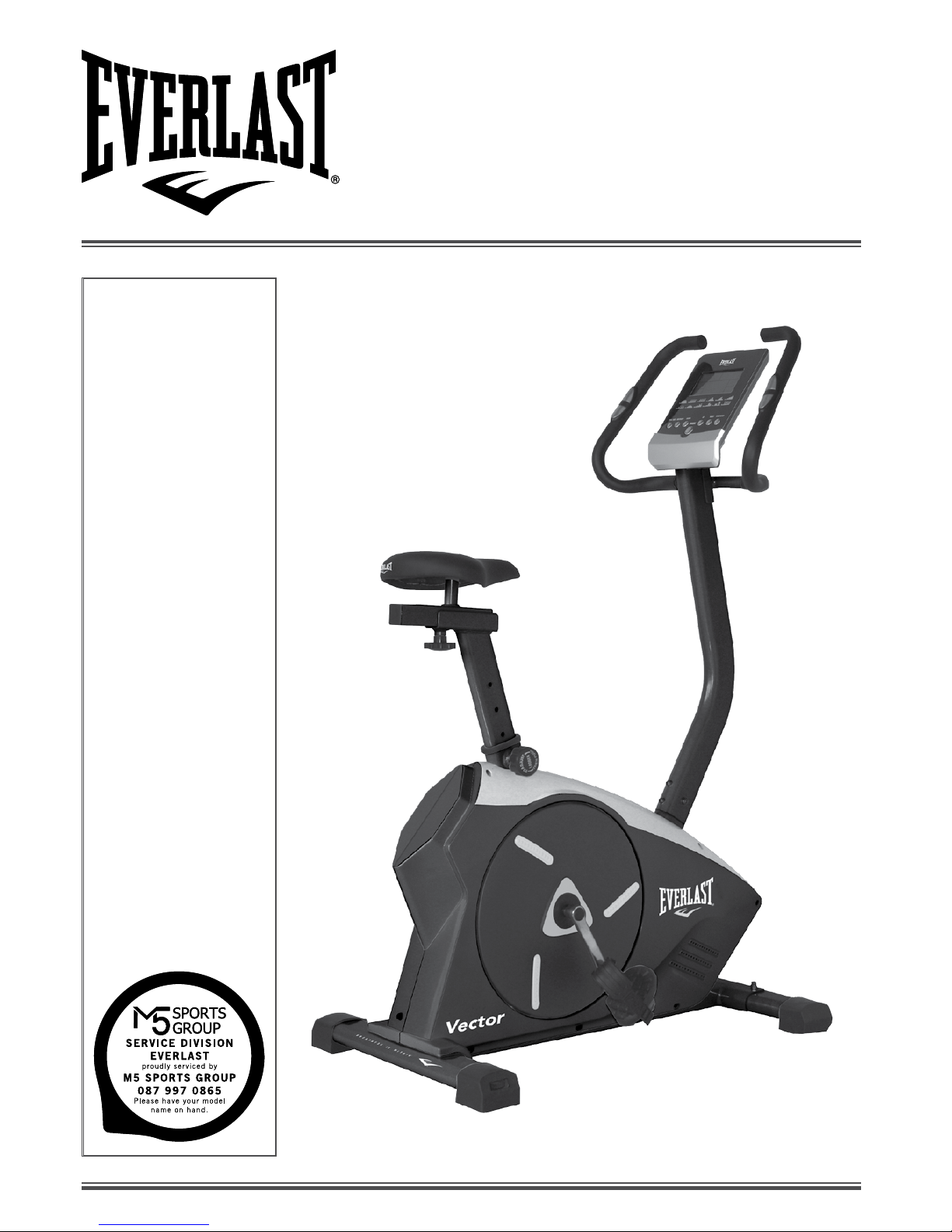
VECTOR BIKE
RONS CODE
10381
www.everlast.com
VECTOR BIKE
USER MANUAL
2
For queries or additional product information, please call our Service Centre on:
087 997 0865
Please have your model name on hand.
www.everlast.com
TABLE OF CONTENTS
SAFETY INFORMATION 3
COMPONENTS PARTS 4-5
ASSEMBLY INSTRUCTIONS 6-10
COMPUTER FUNCTION 11-12
MAINTENANCE 13
TROUBLE SHOOTING 14
EXERCISING INFORMATION 15-17
PRE AND POST STRETCHING EXERCISES 18-19
EXPOLDED VIEW 20-21
PARTS LIST 22
SERVICE WARRANTY 23
SPECIFICATIONS FOR EVERLAST VECTOR BIKE
TENSION Electronic Control Tension
SEAT ADJUSTMENT Horizontal / Vertical
PRODUCT SIZE L 950 X W 540 X H 1470 mm
BREAK SYSTEM Auto Brake System
FLYWHEEL 7 kgs
MAXIMUM USER WEIGHT 150 kgs
PROGRAM 13 Programs
COMPUTER FUNCTION Time, Speed, Distance, Calories, Pulse, ODO, Body Fat, Watt
HAND PULSE METER Yes

3
For queries or additional product information, please call our Service Centre on:
087 997 0865
Please have your model name on hand.
www.everlast.com
SAFETY INFORMATION
ASSEMBLY
• Check you have all the components and tools listed,
bearing in mind that, for ease of assembly, some
components are pre-assembled.
• Keep children and animals away from the work
area, small parts could choke if swallowed.
• Make sure you have enough space to layout the
parts before starting.
• Assemble the item as close to its final position (in
the same room) as possible.
• Position the equipment on a clear, level surface.
• Dispose of all packaging carefully and responsibly.
• Only one person at a time should use the equipment.
• Keep hands away from all moving parts.
• Always wear appropriate workout clothing when
exercising. Do not wear loose or baggy clothing, since it
may get caught in the equipment. Wear athletic shoes
to protect your feet while exercising.
• Do not place any sharp objects around the
equipment.
• Disabled persons should not use the equipment
without a qualified person or doctor in attendance.
• Max user weight 150kgs.
• This product conforms to: (BS EN957) - PARTS 1
and 2 class (H) - Home Use - Class (C).
• This exercise product has been designed and
manufactured to comply with the latest (BS EN 957)
British and European Safety Standards.
USE
• It is the responsibility of the owner to ensure that all
users of this product are properly informed as to how
to use this product safely.
• This product is intended for domestic use only. Do
not use in any commercial, rental, or institutional
setting.
• Before using the equipment to exercise, always do
stretching exercises to properly warm up.
• If the user experiences dizziness, nausea, chest
pain, or other abnormal symptoms stop the workout
and seek immediate medical attention.
IMPORTANT - PLEASE READ FULLY BEFORE ASSEMBLY OR USE
TO REDUCE THE RISK OF SERIOUS INJURY, READ THE ENTIRE MANUAL BEFORE YOU ASSEMBLE OR
OPERATE THE EVERLAST POWER GYM. IN PARTICULAR, NOTE THE FOLLOWING SAFETY PRECAUTIONS:
WARNING: Before beginning any exercise program, consult your Doctor. This is especially important for
persons over the age of 35 or persons with pre-existing health problems. You MUST read all instructions before
using any fitness equipment. The manufacturer and its associates and partners assumes no responsibility for
personal injury or property damage sustained by or through the use of this product.
PHYSICIAN WARNING: Not all exercise equipment and training programs are suitable for everybody.It
is recommended that you consult your physician before using this equipment or beginning this or any other
training program.
4
For queries or additional product information, please call our Service Centre on:
087 997 0865
Please have your model name on hand.
www.everlast.com
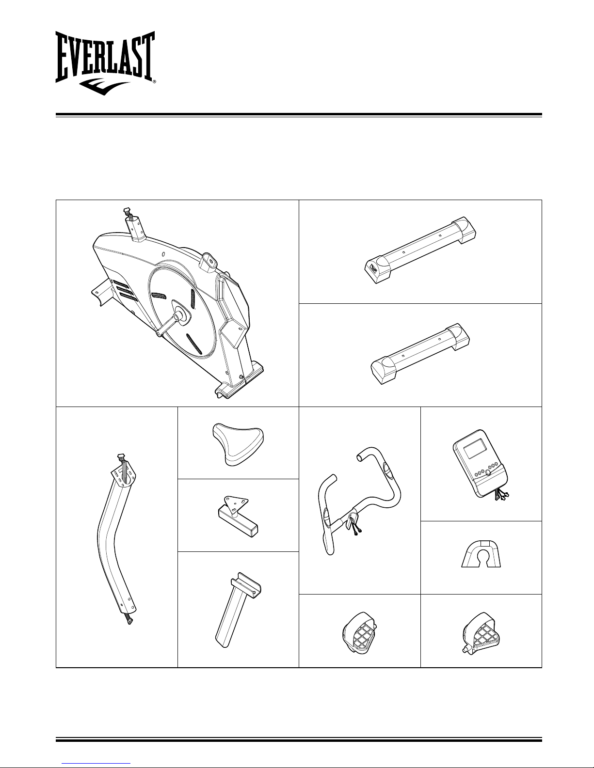
COMPONENTS - PARTS
NOTE: if you have damaged or missing components, call the service division on 087 997 0865
IMPORTANT - PLEASE CHECK YOU HAVE ALL THE PARTS LISTED BELOW
NOTE: SOME OF THE SMALLER PARTS MAY BE PRE- FITTED TO LARGER COMPONENTS. PLEASE CHECK
CAREFULLY BEFORE CONTACTING US REGARDING ANY MISSING PARTS.
No.1
Main Frame x 1pc
No.4
Reart Stabilizer x 1pc
No.6
Front Stabilizer x 1pc
No.3
Front Post x 1pc
No.46
Seat x 1pc
No.2
Handlebar x 1pc
No.39
Computer x 1pc
No.7
Seat Slider x 1pc
No.72
Handlebar Decorative Cover
x 1pc
No.5
Seat Post x 1pc
No.27
Left Padel x 1pc
No.28
Right Padel x 1pc
5
For queries or additional product information, please call our Service Centre on:
087 997 0865
Please have your model name on hand.
www.everlast.com
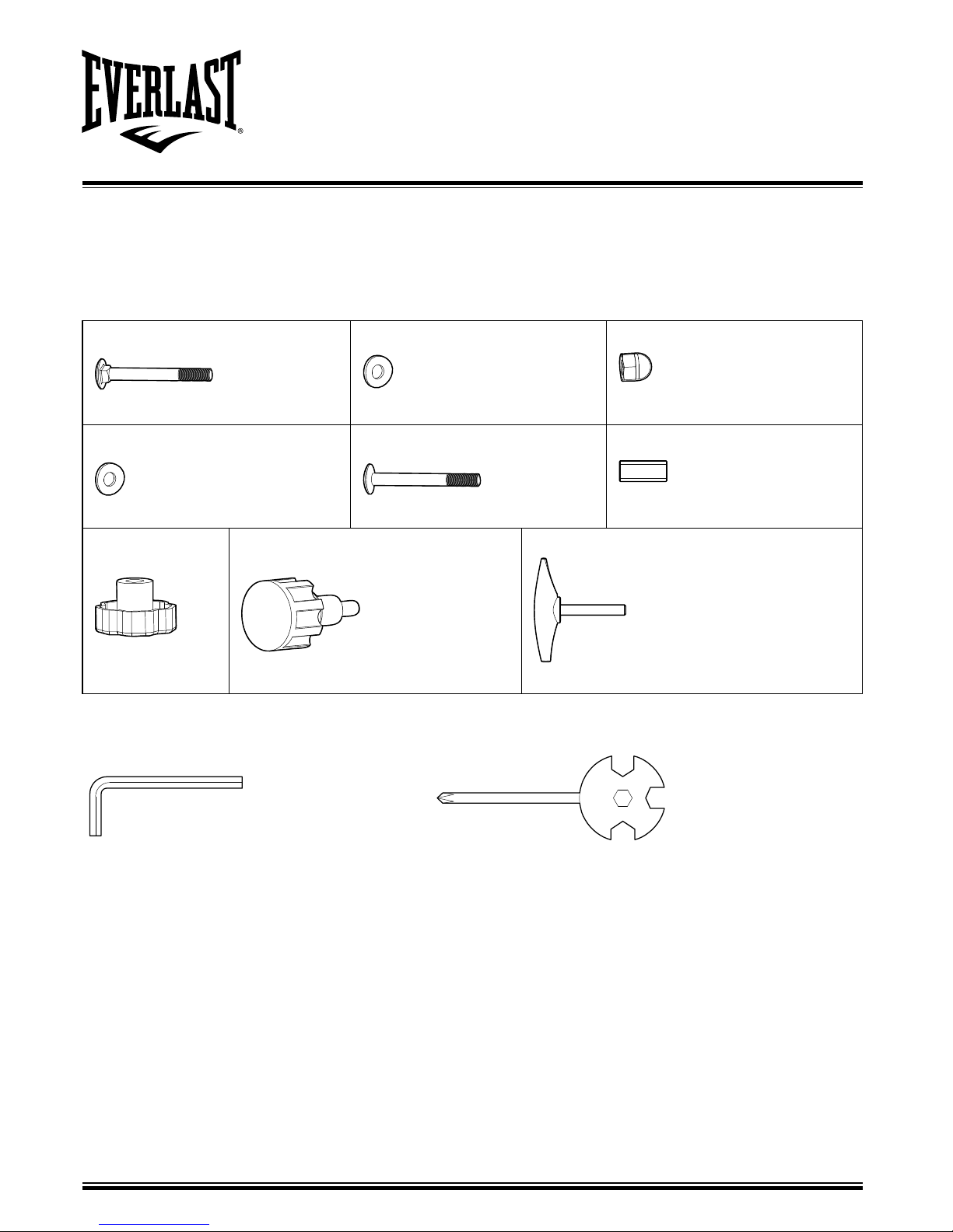
COMPONENTS - PARTS
NOTE: if you have damaged or missing components, call the service division on 087 997 0865
IMPORTANT - PLEASE CHECK YOU HAVE ALL THE PARTS LISTED BELOW
NOTE: SOME OF THE SMALLER PARTS MAY BE PRE- FITTED TO LARGER COMPONENTS. PLEASE CHECK
CAREFULLY BEFORE CONTACTING US REGARDING ANY MISSING PARTS.
No.60
M8 x 55 mm Carriage Bolt x 2pcs
No.58
ø8 x ø16 x T1.5 Washer x 4pcs
No.59
M8 Cap Nut x 2pcs
No.59
M8 Cap Nut x 2pcs
No.61
M8 x 55 mm Hexagon Bolt x 2pcs
No.73
ø12 x ø8 x L30 Bushing x 1pc
No.50
M10 Knob x 1pc
No.51
M16 Seat Height Adjustable Knob x 1pc
No.74
M8 x 55 Handlebar Adjustable Knob x 1pc
Tool
S6 Allen Wrench x 1pc Multi Hex Tool with Phillips Screwdriver x 1pc
70
28
58
61
4
6
1
27
58
59
60
6
For queries or additional product information, please call our Service Centre on:
087 997 0865
Please have your model name on hand.
www.everlast.com
ASSEMBLY INSTRUCTIONS
IMPORTANT - ASSEMBLE WITH ALL NUTS AND BOLTS LOOSE AT FIRST, ONLY TIGHTEN AFTER
COMPLETING ALL ASSEMBLY STEPS.
1. UNPACK THE CARTON AND PLACE ALL PARTS ON THE FLOOR.
2. CAREFULLY REMOVE ALL PACKING MATERIAL AND CHECK EACH PART WITH THE MANUAL FIRST.
3. REMEMBER SOME PARTS ARE PRE-FITTED TO LARGER COMPONENTS.
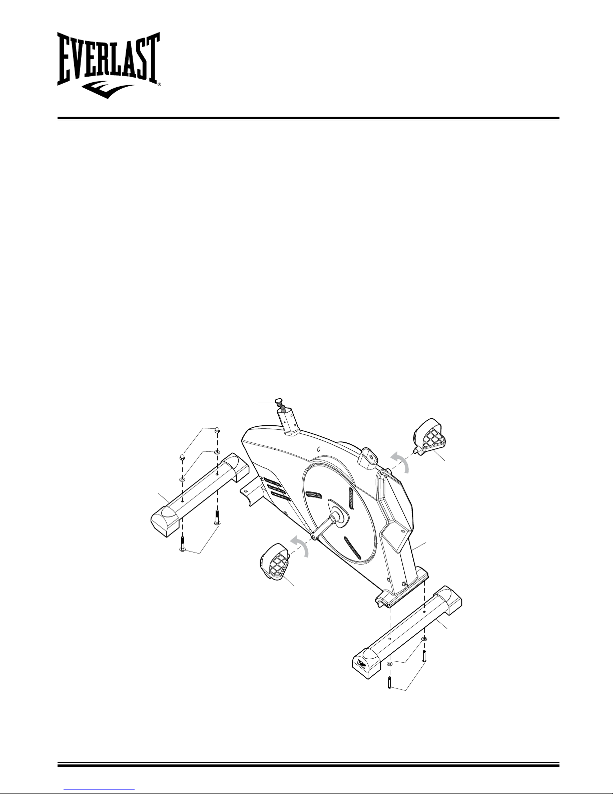
STEP 1
1. Attach the Front Stabilizer (6) onto the front curve of the Main Frame (1) with 2pcs x Carriage Bolt (60), 2pcs
Flat Washer (58) and 2pcs x Cap Nut (59). Tighten cap nuts with the Multi Hex Tool provided.
2. Attach the Rear Stabilizer (4) onto the front curve of the Main Frame (1) with 2pcs x Hexagon Bolt (61), 2pcs x
Flat Washer (58) and 2pcs x Cap Nut (59). Tighten cap nuts with the Allen Wrench S6 provided.
3. The Cranks, Pedal Shafts, and Foot Pedals are marked “R” for Right and “L” for Left.
4. Insert pedal shaft of Left Foot Pedal (27) into threaded hole in the left crank. Turn the pedal shaft by hand in
counter-clockwise direction until snug.
Note: DO NOT turn the pedal shaft in the clockwise direction, doing so will strip the threads.
5. Tighten the pedal shaft of Left Foot Pedal (27) with the Multi Hex Tool with Phillips Screwdriver provided.
6. Insert pedal shaft of Right Foot Pedal (28) into threaded hole in right crank. Turn the pedal shaft by hand in
clockwise direction until snug. Tighten the pedal shaft of Right Foot Pedal (28) with the Multi Hex Tool with
Phillips Screwdriver provided.
38
3
38
58
62
1
6264
70
7
For queries or additional product information, please call our Service Centre on:
087 997 0865
Please have your model name on hand.
www.everlast.com
ASSEMBLY INSTRUCTIONS
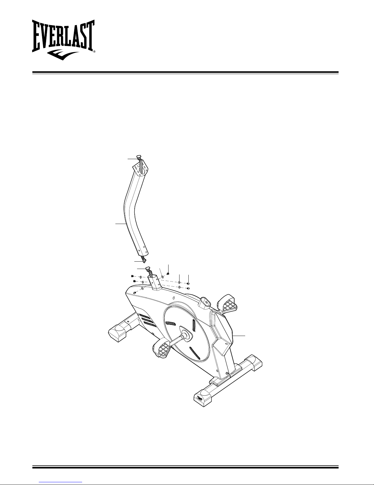
STEP 2
1. Remove 6pcs x Hexagon Bolt (62), 4pcs x Curve Washer (64) and 2pcs x Flat Washers (58) from the tube of
Main Frame (1). Remove bolts with S6 Allen Wrench provided.
2. Connect the Sensor Wire (70) from the Main Frame (1) to the Extension Sensor Wire (38) from the Meter Post
(3).
3. Insert the Meter Post (3) onto the tube of Main Frame (1) and secure with 6pcs x Hexagon Bolt (62), 4pcs
x Curve Washer (64) and 2pcs x Flat Washer (58) that were removed. Tighten bolts with S6 Allen Wrench
provided.
38
3
7
5
1
51
50
46
66
65
8
For queries or additional product information, please call our Service Centre on:
087 997 0865
Please have your model name on hand.
www.everlast.com
ASSEMBLY INSTRUCTIONS
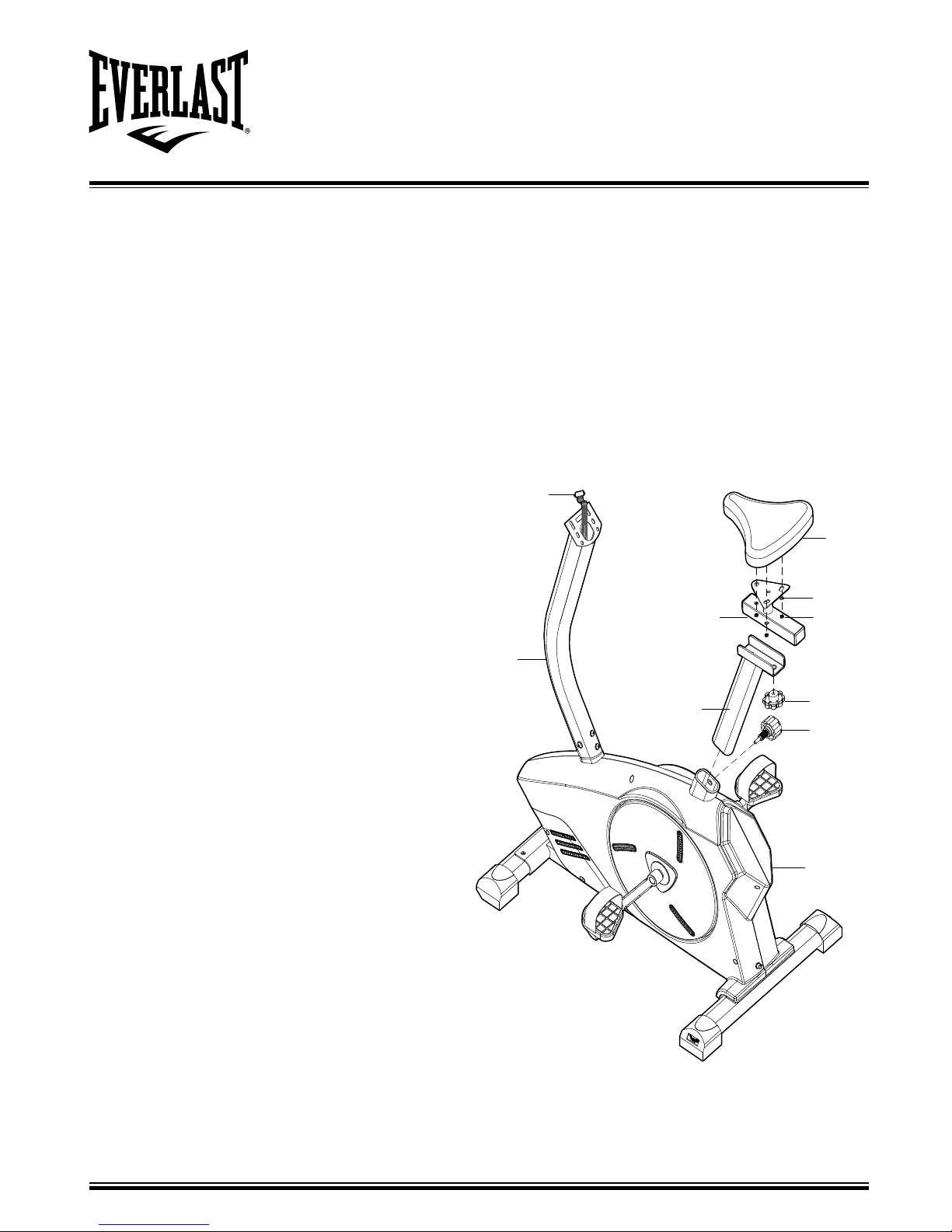
STEP 3
1. Remove 3pcs x Flat Washer (66) and 3pcs x Nylon Nut (65) from underside of the Seat Cushion (46). Guide
bolts on underside of the Seat Cushion (46) through holes on top of the Slide Tube (7), attach with removed
3pcs x Flat Washer (66) and 3pcs x M8 Nylon Nut (65). Tighten nylon nuts with Multi Hex Tool with Phillips
Screwdriver provided.
2. Attach the Slide Tube (7) to the Seat Post (5) with Knob (50) by turning it in a clockwise direction to lock the
Slide Tube (7) in the suitable position.
3. Insert the Seat Post (5) into the Seat Post Plastic Bushing on the tube of the Main Frame (1) and then attach
the M16 Seat Height Adjustment Knob (51) onto the tube of the Main Frame (1) by turning it in a clockwise
direction to lock the Seat Post (5) in the suitable position.
4. Turn the M16 Seat Height Adjustment Knob (51) in a counterclockwise direction to release the Seat Post (5)
and then slide the Seat Post (5) up or down slightly to the desired hole for the suitable position. Lock the Seat
Post (5) in place by tightening the Seat Height Adjustment Knob (51) in a clockwise direction.
5. Adjusting the Seat Back and Forth Turn the Knob
(50) in a counterclockwise direction to release the
Slide Tube (7) and then slide the Slide Tube (7) back
or forth slightly to the desired hole for the suitable
position. Lock the Slide Tube (7) in place by tightening
the Knob (50) in a clockwise direction.
NOTE: When adjusting the height of seat post, make
sure the seat post plastic bushing does not exceed
the mark line on the seat post.
 Loading...