

EVERLAST
CC
PAC
MOSFET
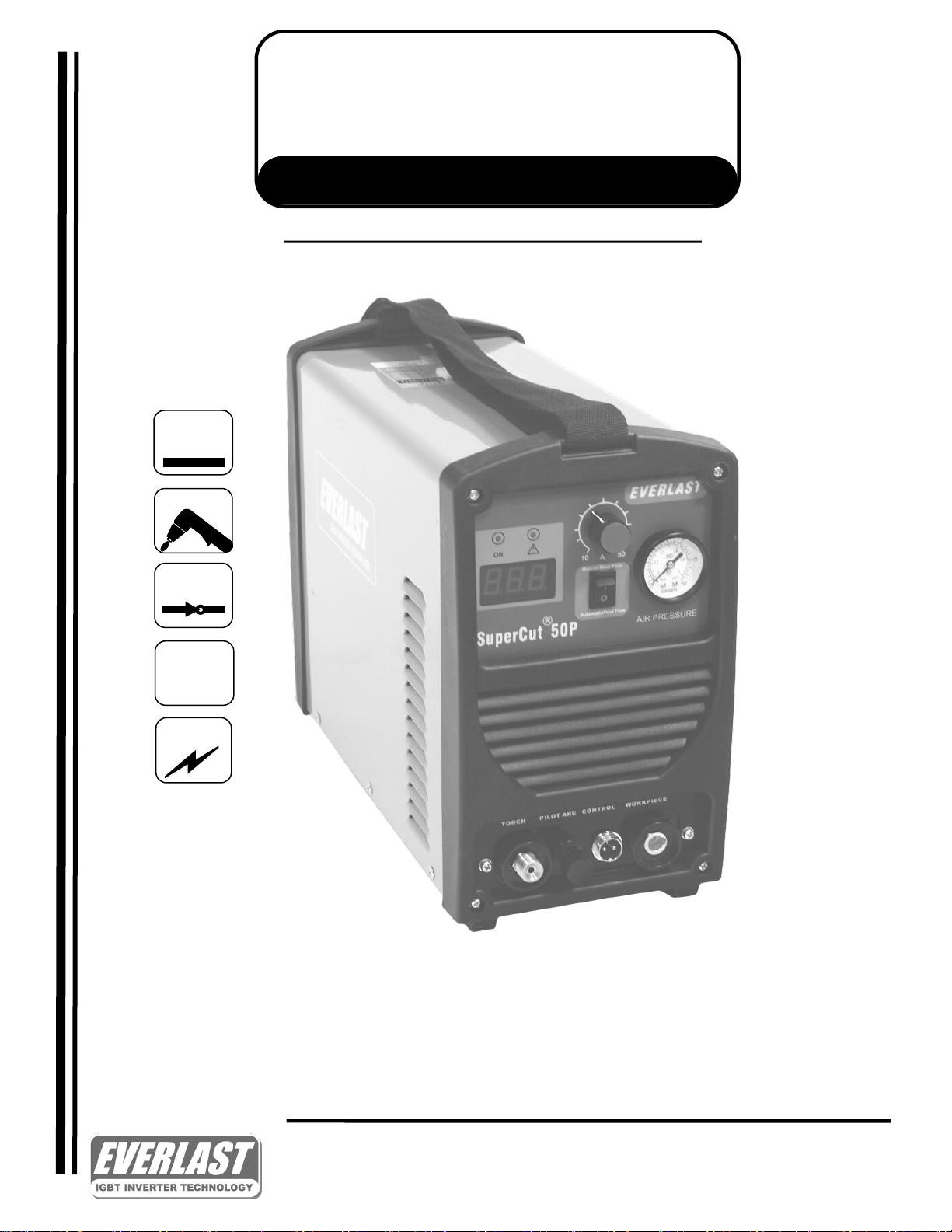
SUPERCUT SERIES
Mosfet inverter plasma cutter
1
PHASE
~
DC
Operator’s Manual For
SUPERCUT 50/50P PLASMA CUTTER
Safety, Setup and General Use Guide
Rev. 1 0 00422-14
everlastwelders.com
1-877-755-9353
329 Lileeld Ave. South San Francisco, CA 94080 USA
Specicaons and Accessories subject to change without noce.

Table of contents
Secon……………………………………………………………..Page
Leer to the Customer ………………...………………….
Everlast Contact Informaon…………………………….
Safety Precauons…………………………………………....
Introducon and Specicaons…………………….…..
Unit Specicaons……………………….……………………
General Overview…………….…..…………………………..
General Use and Care………...……………………………..
Quick Setup Guide, Plasma Connecons…..………..
Quick Setup Guide, Rear Connecon for Plasma…
Front Panel Features and Controls……………………..
Rear Panel Features and Controls……………………...
Plasma Funcon and Operaon………………………....
Plasma Torch……...……………………………….……………..
Troubleshoong………………………………………………....
3
4
5
9
10
11
11
12
13
14
16
17
22
23
NOTE: Product Specicaons and features are subject to change without noce. While every aempt has
been made to provide the most accurate and current informaon possible at the me of publicaon, this manual is intended to be a general guide and not intended to be exhausve in its content regarding safety, welding,
or the operaon/maintenance of this unit. Everlast Power Equipment INC. does not guarantee the accuracy,
completeness, authority or authencity of the informaon contained within this manual. The owner of this
product assumes all liability for its use and maintenance. Everlast Power Equipment INC. does not warrant this
product or this document for tness for any parcular purpose, for performance/accuracy or for suitability of
applicaon. Furthermore, Everlast Power Equipment INC. does not accept liability for injury or damages, consequenal or incidental, resulng from the use of this product or resulng from the content found in this document or accept claims by a third party of such liability.
2

Dear Customer,
THANKS! You had a choice, and you bought an Everlast. We appreciate you
as a customer and hope that you will enjoy years of use from your welder.
Please go directly to the Everlast website to register your unit and receive your warranty infor-
maon. Your unit registraon is important should any informaon such as product updates or re-
calls be issued. It is also important so that we may track your sasfacon with Everlast products
and services. If you are unable to register by website, contact Everlast directly through the sales
department through the main customer service number in your country. Your unit will be registered and warranty will be issued and in full eect. Keep all informaon regarding your purchase.
In the event of a problem you must contact technical support before your welder can be a candidate for warranty service and returned.
Please review the current online warranty statement and informaon found on the web-
site of the Everlast division located in or nearest to your country. Print it for your records
and become familiar of its terms and condions.
Everlast oers full technical support, in several dierent forms. We have online support available
through email, and a welding support forum designed for customers and noncustomer interacon.
Technical advisors are acve on the forum daily. We also divide our support into two divisions:
technical and welding performance. Should you have an issue or queson concerning your unit,
please contact performance/technical support available through the main company headquarters
available in your country. For best service call the appropriate support line and follow up with an
email, parcularly during o hours, or in the event you cannot reach a live person. In the event
you do not reach a live person, parcularly during heavy call volume mes, holidays, and o hours,
leave a message and your call will normally be returned within 24 hours. Also,for quick answers to
your basic quesons, join the company owned forum available through the website. You’ll nd
knowledgeable, helpful people and sta available to answer your quesons, and perhaps nd a
topic that already addresses your queson at hp://www.everlastgenerators.com/forums/.
Should you need to call or write, always know your model name, purchase date and welder manufacturing inspecon date. This will assure the quick and accurate customer service. REMEMBER:
Be as specic and informed as possible. Technical and performance advisors rely upon you to
carefully describe the condions and circumstances of your problem or queson. Take notes of
any issues as best you can. You may be asked many quesons by the advisors to clarify problems or issues that may seem very basic. However, diagnosis procedures MUST be followed to
begin the warranty process. Advisors can’t assume anything, even with experienced users, and
must cover all aspects to properly diagnose the problem. Depending upon your issue, it is advisable to have basic tools handy such as screwdrivers, wrenches, pliers, and even an inexpensive
test meter with volt/ohm funcons before you call.
Let us know how we may be of service to you should you have any quesons.
Sincerely,
Everlast Customer Service
3

Serial number: __________________________
Model number: ____________________________
Date of Purchase___________________________
EVERLAST
Contact Information
Everlast US:
Everlast consumer sasfacon email: sales@everlastwelders.com
Everlast Website: everlastwelders.com
Everlast Technical Support: support@everlastwelders.com
Everlast Support Forum: hp://www.everlastgenerators.com/forums/index.php
Main toll free number: 1-877-755 WELD (9353) 9am—5pm PST M-F
11am-4pm PST Sat.
FAX: 1-650-588-8817
Everlast Canada:
Everlast consumer sasfacon email: sales@everlastwelders.ca
Everlast Website: everlastwelders.ca
Everlast Technical Support: sales@everlastwelders.ca
Telephone: 905-637-1637 9am-4:30pm EST M-F
10am-1pm EST Sat.
FAX: 1-905-639-2817
Everlast Austrailia:
Sydney: 5A Karloo Parade Newport NSW 2106
(02) 9999 2949
Port Macquarie: 2B Pandorea Place Port Macquarie
(02) 8209 3389
Aer hours support: 0413 447 492
Everlast Technical Support: support@pickproducts.com
4
Safety Precautions
Everlast is dedicated to providing you with the best possible equipment and
service to meet the demanding jobs that you have. We want to go beyond delivering a satisfactory product to you. That is the reason we offer technical sup-
port to assist you with your needs should an occasion occur. With proper use
and care your product should deliver years of trouble free service.
Safe operation and proper maintenance is your responsibility.
We have compiled this operator’s manual, to instruct you in basic safety, oper-
ation and maintenance of your Everlast product to give you the best possible
experience. Much of welding and cutting is based upon experience and common sense. As thorough as this welding manual may be, it is no substitute for
either. Exercise extreme caution and care in all activities related to welding or
cutting. Your safety, health and even life depends upon it. While accidents are
never planned, preventing an accident requires careful planning.
Please carefully read this manual before you operate your Everlast unit. This
manual is not only for the use of the machine, but to assist in obtaining the
best performance out of your unit. Do not operate the unit until you have read
this manual and you are thoroughly familiar with the safe operation of the unit.
If you feel you need more information please contact Everlast Support.
The warranty does not cover improper use, maintenance or consumables. Do
not attempt to alter or defeat any piece or part of your unit, particularly any
safety device. Keep all shields and covers in place during unit operation should
an unlikely failure of internal components result in the possible presence of
sparks and explosions. If a failure occurs, discontinue further use until malfunctioning parts or accessories have been repaired or replaced by qualified
personnel.
Note on High Frequency electromagnetic disturbances:
Certain welding and cutting processes generate High Frequency (HF) waves.
These waves may disturb sensitive electronic equipment such as televisions,
radios, computers, cell phones, and related equipment. High Frequency may
also interfere with fluorescent lights. Consult with a
turbance is noted. Sometimes, improper wire routing or poor shielding may be
the cause.
HF can interfere with pacemakers. See EMF warnings in following safety section for further information. Always consult your physician before entering an
area known to have welding or cutting equipment if you have a pacemaker.
5
licensed
electrician if dis-

SAFETY PRECAUTIONS
These safety precautions are for protection of safety and health. Failure to
follow these guidelines may result in serious injury or death. Be careful to
read and follow all cautions and warnings. Protect yourself and others.
Welding and cutting processes produce high levels of ultraviolet (UV) radiation that
can cause severe skin burn and damage. There are other potential hazards involved
with welding such as severe burns and respiratory related illnesses. Therefore observe the following to minimize potential accidents and injury:
Use appropriate safety glasses with wrap around shields while in the work area, even
under welding helmets to protect your eyes from flying sparks and debris. When chipping slag or grinding, goggles and face shields may be required.
When welding or cutting, always use an approved shielding device, with the correct
shade of filter installed. Always use a welding helmet in good condition. Discard any
broken or cracked filters or helmets. Using broken or cracked filters or helmets can
cause severe eye injury and burn. Filter shades of no less than shade 5 for cutting
and no less than shade 9 for welding are highly recommended. Shades greater than 9
may be required for high amperage welds. Keep filter lenses clean and clear for maximum visibility. It is also advisable to consult with your eye doctor should you wear
contacts for corrective vision before you wear them while welding.
Do not allow personnel to watch or observe the welding or cutting operation unless
fully protected by a filter screen, protective curtains or equivalent protective equipment. If no protection is available, exclude them from the work area. Even brief exposure to the rays from the welding arc can damage unprotected eyes.
Always wear hearing protection because welding and cutting can be extremely noisy.
Ear protection is necessary to prevent hearing loss. Even prolonged low levels of
noise has been known to create long term hearing damage. Hearing protection also
further protects against hot sparks and debris from entering the ear canal and doing
harm.
Always wear personal protective clothing. Flame proof clothing is required at all
times. Sparks and hot metal can lodge in pockets, hems and cuffs. Make sure loose
clothing is tucked in neatly. Leather aprons and jackets are recommended. Suitable
welding jackets and coats may be purchased made from fire proof material from
welding supply stores. Discard any burned or frayed clothing. Keep clothing away
from oil, grease and flammable liquids.
Leather boots or steel toed leather boots with rubber bottoms are required for adequate foot protection. Canvas, polyester and other man made materials often found
in shoes will either burn or melt. Rubber or other non conductive soles are necessary
to help protect from electrical shock.
Flame proof and insulated gauntlet gloves are required whether welding or cutting or
handling metal. Simple work gloves for the garden or chore work are not sufficient.
Gauntlet type welding gloves are available from your local welding supply companies.
Never attempt to weld with out gloves. Welding with out gloves can result in serious
burns and electrical shock. If your hand or body parts comes into contact with the
arc of a plasma cutter or welder, instant and serious burns will occur. Proper hand
protection is required at all times when working with welding or cutting machines!
6
SAFETY PRECAUTIONS
WARNING! Persons with pacemakers should not weld, cut or be in the welding area
until they consult with their physician. Some pacemakers are sensitive to EMF radiation
and could severely malfunction while welding or while being in the vicinity of someone
welding. Serious injury or death may occur!
Welding and plasma cutting processes generate electro-magnetic fields and radiation.
While the effects of EMF radiation are not known, it is suspected that there may be
some harm from long term exposure to electromagnetic fields. Therefore, certain precautions should be taken to minimize exposure:
Lay welding leads and lines neatly away from the body.
Never coil cables around the body.
Secure cables with tape if necessary to keep from the body.
Keep all cables and leads on the same side the body.
Never stand between cables or leads.
Keep as far away from the power source (welder) as possible while welding.
Never stand between the ground clamp and the torch.
Keep the ground clamp grounded as close to the weld or cut as possible.
Welding and cutting processes pose certain inhalation risks. Be sure to follow any
guidelines from your chosen consumable and electrode suppliers regarding possible
need for respiratory equipment while welding or cutting. Always weld with adequate
ventilation. Never weld in closed rooms or confined spaces. Fumes and gases released while welding or cutting may be poisonous. Take precautions at all times.
Any burning of the eyes, nose or throat are signs that you need to increase ventilation.
Stop immediately and relocate work if necessary until adequate ventilation is ob-
tained.
Stop work completely and seek medical help if irritation and discomfort persists.
WARNING! Do not weld on galvanized steel, stainless steel, beryllium, titanium, cop-
per, cadmium, lead or zinc without proper respiratory equipment and or ventilation.
WARNING! This product when used for welding or cutting produces fumes and gas-
es which contains chemicals known to the State of California to cause birth defects
and in some cases cancer. (California Safety and Health Code §25249.5
WARNING! Do not weld or cut around Chlorinated solvents or degreasing areas.
Release of Phosgene gas can be deadly. Consider all chemicals to have potential
deadly results if welded on or near metal containing residual amounts of chemicals.
Keep all cylinders upright and chained to a wall or appropriate holding pen. Certain
regulations regarding high pressure cylinders can be obtained from OSHA or local
regulatory agency. Consult also with your welding supply company in your area for
further recommendations. The regulatory changes are frequent so keep informed.
All cylinders have a potential explosion hazard. When not in use, keep capped and
closed. Store chained so that overturn is not likely. Transporting cylinders incorrectly
can lead to an explosion. Do not attempt to adapt regulators to fit cylinders. Do not
use faulty regulators. Do not allow cylinders to come into contact with work piece or
work. Do not weld or strike arcs on cylinders. Keep cylinders away from direct heat,
flame and sparks.
et seq
.)
7
SAFETY PRECAUTIONS
continued
WARNING! Electrical shock can kill. Make sure all electrical equipment is properly
grounded. Do not use frayed, cut or otherwise damaged cables and leads. Do not
stand, lean or rest on ground clamp. Do not stand in water or damp areas while welding or cutting. Keep work surface dry. Do not use welder or plasma cutter in the rain
or in extremely humid conditions. Use dry rubber soled shoes and dry gloves when
welding or cutting to insulate against electrical shock. Turn machine on or off only
with gloved hand. Keep all parts of the body insulated from work, and work tables.
Keep away from direct contact with skin against work. If tight or close quarters necessitates standing or resting on work piece, insulate with dry boards and rubber
mats designed to insulate the body from direct contact.
All work cables, leads, and hoses pose trip hazards. Be aware of their location and
make sure all personnel in area are advised of their location. Taping or securing cables with appropriate restraints can help reduce trips and falls.
WARNING! Fire and explosions are real risks while welding or cutting. Always keep
fire extinguishers close by and additionally a water hose or bucket of sand. Periodically check work area for smoldering embers or smoke. It is a good idea to have
someone help watch for possible fires while you are welding. Sparks and hot metal
may travel a long distance. They may go into cracks in walls and floors and start a fire
that would not be immediately visible. Here are some things you can do to reduce the
possibility of fire or explosion:
Keep all combustible materials including rags and spare clothing away from area.
Keep all flammable fuels and liquids stored separately from work area.
Visually inspect work area when job is completed for the slightest traces of smoke
or embers.
If welding or cutting outside, make sure you are in a cleared off area, free from
dry tender and debris that might start a forest or grass fire.
Do not weld on tanks, drums or barrels that are closed, pressurized or anything
that held flammable liquid or material.
Metal is hot after welding or cutting! Always use gloves and or tongs when handling
hot pieces of metal. Remember to place hot metal on fire-proof surfaces after handling. Serious burns and injury can result if material is improperly handled.
WARNING! Faulty or poorly maintained equipment can cause injury or death. Prop-
er maintenance is your responsibility. Make sure all equipment is properly maintained
and serviced by qualified personnel. Do not abuse or misuse equipment.
Keep all covers in place. A faulty machine may shoot sparks or may have exploding
parts. Touching uncovered parts inside machine can cause discharge of high
amounts of electricity. Do not allow employees to operate poorly serviced equipment.
Always check condition of equipment thoroughly before start up. Disconnect unit
from power source before any service attempt is made and for long term storage or
electrical storms.
Further information can be obtained from The American Welding Society (AWS) that
relates directly to safe welding and plasma cutting. Additionally, your local welding
supply company may have additional pamphlets available concerning their products.
Do not operate machinery until your are comfortable with proper operation and are
able to assume inherent risks of cutting or welding.
8

Introduction and Specifications Section 1
SuperCut 50/50P
Air Regulator
AG-60 12 . Plasma Torch
Consumable Starter Kit
Work Clamp
NOTE: Accessory and consumable style and quanes are subject to change without noce. Consumable starter kits provide only enough
consumables to get started. Extra consumables can be purchased through Everlast or almost any local welding supply store.
9

Introduction and Specifications Section 1
Specicaon SuperCUT 50/50P
Inverter Type Analog, MOSFET
Minimum/Maximum Rated Output 10 A/84 V - 50 A/100 V
Start Type HF Start
Torch Type Everlast AG 60 12 .
Duty Cycle @ Rated Amps/Volts ( 40° C)
(Output V/A)
OCV (U0) 220 V
Voltage Input (U1) Dual Voltage: 120 V/ 240 V; 50/60Hz 1 Phase
Maximum Inrush Amps (I1MAX) 31A @ 120V; 39@ 240V
Maximum Rated Eecve Amps (I1EFF) 25 A @ 120 V, 39A @ 240V; 3
CNC Port NO
Air Post Flow Timer Fixed
Minimum Air Compressor Requirement 3.5 - 4 CFM @ 90 psi/
Duty Cycle/ Over Current Protecon Yes
Minimum Operang Air Pressure None
Recommended Operang Air Pressure
(Set with Air Flow set “Test”)
Maximum Supplied Air Pressure
(From Compressor/Tank)
Recommended Maximum Average Cut Thickness 3/8”
Recommended Daily Maximum
Average Cut Thickness (CNC)
Rated Maximum Quality Cut @
10-12 IPM (Steel)
Max Severance Cut @ 3 IPM (Steel ) 3/4”
60% @ 50 A/ 100V 240 V
100% @ 40 A/ 96 V 240 V
60% @ 25 A/ 90 V 120 V
100% @ 20 A/ 88 V 120 V
30-60 gallon reserve
55-65 psi
85 psi
3/16-1/4”
1/2-5/8”
Minimum Water Ingress Protecon Standard IP21S
Eciency >85%
Cooling Method Full Time High Velocity Fan with Tunnel design
Dimensions (approximate) 18” H X 10” W X 25” L
Weight (Bare Unit) 20 lbs
Decrease maximum cut thickness values for aluminum and stainless by approximately 35%.
When evaluang a plasma cuer for daily service, do not consider maximum severance cut values as criteria for roune use! These maximum specicaons are
intended for occasional situaons that might require such a cut. Plan the unit’s daily use around the recommended average cut thickness for best results and
speed. This is an industry standard recommendaon and is not unique to Everlast Plasma Cuers. Plasma performance specicaons are based on reasonable
environmental condions with well maintained units, and cung with new consumables using opmum air pressure. Actual performance results may vary in
the eld due to variable condions, power supply, air pressure, air quality, consumable wear etc.
10

Section 1
Introduction and Specifications
General overview: The Supercut 50 and 50P plasma
cuers feature a light weight MOSFET inverter design.
The entry level SuperCut 50 and 50P are designed to
meet the demands of people having occasional plasma
cung needs such as homeowners, or hobbyists with a
small project or occasional repair work in mind. These
units are a budget minded alternave to oxy fuel cung ,
intended for hobbyists who do not require producon or
roune fabricang dues from their plasma cuers. If
taken care of and properly maintained these units should
see a useful service life providing rapid, clean and inexpensive cuts. Warranty period is 3 years from date of
shipping. For warranty details please see the warranty
secon at www.everlastwelders.com.
General Use and Care: Care should be taken to keep the
unit out of direct contact with water spray. The unit is
rated IP21S, which rates it for light contact with dripping
water. It is a good idea to remove the plasma cuer
from the vicinity of any water or moisture source to reduce the possibility of electrocuon or shock. Never operate in standing water.
Every 1-2 months, depending upon use, the plasma
cuer should be unplugged, opened up and carefully
cleaned with compressed air. Regular maintenance will
extend the life of the unit.
IMPORTANT: Before opening the unit for any reason,
including adjusng the point gap, make sure the unit
has been unplugged for at least 10 minutes to allow
me for the capacitors to fully discharge. Severe shock
and/or death can occur.
Do not restrict air ow or movement of air around the
plasma cuer. Allow a buer distance of 2 from all
sides if possible, with a minimum distance of at least 18”
clearance. Do not operate the unit immediately in the
weld/cut area.
Do not mount in areas that are prone to severe shock or
vibraon. Li and carry the welder by the handle.
Do not direct metallic dust or any dirt intenonally toward the machine, parcularly in grinding and welding
operaons. Make sure the panel is protected from damage.
NOTE: When servicing unit, remove rear plasc panel
rst, the remove metal cover. DO NOT REMOVE FRONT
PLASTIC PANEL! THE FRONT PANEL IS INTEGRAL TO THE
FRAME OF THE UNIT. REMOVING THIS PANEL IS TIME
CONSUMING AND UNECESSARY.
Duty Cycle. The duty cycle has been determined for the
PowerPlasma at 60% @ 50 amps on 240 V operaon.
The duty cycle is based o a 10 minute duty cycle rang at
40° C. This means that the unit is capable of being operated at the max amps for the stated percent of me out of
10 minutes without a break to cool down the unit. For
the remainder of the 10 minute me period, the welder
should rest for maximum life. The temperature light will
come on and the unit will automacally stop cung when
an overheat condion has occurred. Stop trying to cut
immediately. Heat will connue to be generated and
transferred to the electronics aer welding has ceased.
Cung in humid, or hot condions can aect duty cycle
as well. Do not shut down an overheated welder unl it
has safely cooled. Once the overheated condion has
cleared, cung may resume. Do not operate the unit
with the covers removed. Only cycle the power switch to
reset the unit IF the light has not gone out aer 10
minutes. 120V operaon may reduce duty cycle in some
situaons and will necessarily reduce output.
This manual has been compiled to give an overview of
operaon and is designed to oer informaon centered
around safe, praccal use of the plasma cuer. The
welding industry is inherently dangerous. Only YOU, the
operator of this Plasma cuer, can ensure that safe operang pracces are followed, through the exercise of common sense pracces and training. Do not operate this
machine unl you have fully read the manual, including
the safety secon. If you think that you do not have the
skill or knowledge to safely operate the plasma cuer, do
not use this welder unl formal training is received.
11

QUICK SETUP AND USE GUIDE Section 2
QUICK SETUP GUIDE: PLASMA CONNECTIONS
WORK PIECE
25 SERIES CONNECTOR
PILOT ARC USED ON 50P ONLY
PILOT ARC TORCH
CONTROL
v
TO WORK
AG-60 Torch
NOTES:
1) This unit is not equipped with low air pressure safety cut out. Aempng to cut with the unit without air or with low air pressure may
severely damage unit and/or torch. Always verify air pressure before aempng to cut.
2) Do not exceed 85 psi air supply pressure or failure of components may result.
3) Adjust torch operaon pressure to 55-65 for best results with unit set to “constant ow”. If supplied, use the ow meter as depicted in
the torch manual to properly set the air pressure and ow. Do not supply the unit with more than 85 PSI from the compressor.
4) Use ps with smaller orices when cung in 120V mode or at low amperages (<40A). A symptom of a consumable that is too large, is a
wandering arc or spuering arc.
5) Do not aempt to cut with the work clamp removed. The unit will produce the pilot arc without the work clamp connected. The pilot
arc is not designed to cut and excessive use will burn up the consumable and the torch. Keep the pilot arc engaged for lile as possible.
If you noce that the unit does not cut but only scars the surface or cuts less than 1/8” into the metal slowly, and the arc is present,
likely it is an issue with a poor connecon of the work clamp. Poor connecon of the work piece can cause the pilot arc not to transfer
properly. Have someone safely look at the display while aempng a cut. The display should briey drop below 30 amps and then
return to the preset amperage level. If it remains below 30 amps (usually 20-27 amps or so) the pilot arc is not transferring. Stop and
examine the work piece, clamp and even the DINSE connector on the panel. Repair if necessary. If this does not resolve the pilot arc
transfer issue, contact Everlast.
12

QUICK SETUP AND USE GUIDE Section 2
QUICK SETUP GUIDE: REAR CONNECTIONS FOR PLASMA OPERATION
Compressor and Dryer Diagram
Compressor and Air hose w ngs
(Customer Supplied)
Regulator Assembly with built-in
water trap and dirt lter (Included).
Pull knob to set, push to lock in place
1/4” Automove Universal style
quick connector (Included)
Use clamps
Air Dryer/Oil Filter
(Customer Supplied)
1
GAS
INLET
2
4
NOTES: A SEPARATE AIR DRYER BETWEEN THE AIR COMPRESSOR AND FILTER ASSEMBLY MUST BE INSTALLED. IT SHOULD BE INSTALLED AS
CLOSE TO THE PLASMA CUTTER AS PRACTICAL. THIS IS A CUSTOMER SUPPLIED ITEM. THIS WILL REDUCE CUTTING ISSUES SUCH AS SPITTING,
POPPING AND RAPID CONSUMABLE WEAR. THE FILTER THAT IS INCLUDED IS NOT SUFFICIENT TO REMOVE ALL MOISTURE. IT SERVES ONLY AS A
WATER TRAP AND FINE SEDIMENT FILTER. ANY AIR COMPRESSOR SYSTEM PRODUCES MOISTURE IN ALMOST ANY ENVIRONMENT REGARDLESS OF
HUMIDITY LEVELS. DAILY DRAINING OF THE AIR COMPRESSOR IS RECOMMENDED AS WELL. THE AIR SUPPLIED TO THE PLASMA CUTTER SHOULD
BE OF SIMILAR QUALITY USED FOR AUTOMOTIVE PAINTING. DIFFERENT STYLES OF DRYERS ARE AVAILABLE. THE MOST INEXPENSIVE AND COMMONLY AVAILABLE IS THE REPLACEABLE DESSICANT TYPE USED FOR AUTOMOTIVE PAINTING. DAMAGE DONE TO THE TORCH AND THE PLASMA
CUTTER (INCLUDING BUT NOT LIMITED TO: SHORTING, CORROSION AND DETERIORATION OF INTERNAL LINES AND COMPONENTS) AS A RESULT
OF EXCESS MOISTURE IS NOT COVERED UNDER WARRANTY. ADDITIONALLY, A FILTER SHOULD BE INSTALLED IN-LINE OR AT THE COMPRESSOR
THAT WILL FILTER ANY EXCESS OIL OR OIL BLOW-BY FROM THE LINE IF NECESSARY. DO NOT USE WITH OILING SYSTEMS DESIGNED TO AUTOMATI-
CALLY LUBRICATE AIR TOOLS. IT IS ADVISABLE TO USE THE PLASMA CUTTER WITH A NEW AIR HOSE/LINE THAT IS FRESH WITHOUT MOISTURE OR
LUBE CONTAMINATION. IF AIR PRESSURE DROPS FROM THE COMPRESSOR TO THE CUTTER MORE THAN 5-10 PSI, OR AIR FLOW IS INSUFFICENT,
INCREASE TO A LARGER SIZE DRYER/FILTER. FAILURE TO USE THE PROPER DRYER/FILTER IS THE NUMBER ONE CAUSE OF CUTTING ISSUES.
NOTE: WHEN ASSEMBL ING AIR FIL TER NOTICE THE MARKING S THAT ARE
STAMPED ON TOP OF THE REGULATOR HOUSING FOR AIR FLOW DIRECTION.
AIR FLOW DIRECTION WILL BE NOTED AS IN/OUT OR BE STAMPED WITH A
SMALL ARROW FOR AIR FLOW DIRECTION. THE QUICK CONNECT 1/4” MALE
AUTOMOTIVE COUPLING SHOULD BE MOUNTED ON THE SIDE OF THE FILTER
WITH “IN” OR THE ARROW POINTING TO THE MIDDLE OF THE FILTER. ALSO
THE BRASS PLUG INCLUDED WITH THE ACCESSORY PACKAGE SHOULD BE
MOUNTED IN THE CENTER HOLE.
Note: Unit is shipped with out
plug. (Customer supplied.)
13

1. AMP CONTROL
2. ON/TEMP/O.C.
QUICK SETUP AND USE GUIDE Section 2
FRONT PANEL FEATURES AND CONTROLS
3. AMP DISPLAY
4. MANUAL/AUTO FLOW SWITCH
5. TORCH CONNECTOR
PILOT ARC TORCH
CONTROL
v
6. PILOT ARC (50P ONLY)
8. AIR PRESSURE
WORK PIECE
7. WORK CLAMP (25 SERIES)
7. TORCH SWITCH CONNECTOR (2 PIN)
14

Section 2
FRONT PANEL FEATURES AND CONTROLS CONTINUED
POWERPRO FEATURES PARAMETERS PURPOSE
1. Amp Control N/A Controls amperage output.
QUICK SETUP AND USE GUIDE
2. On/Temp/ Duty Cycle On/O On indicator should always be on while the unit is plugged in and the power switch is switched
3. Amp Display N/A Indicates amperage while cung. While adjusng the amperage with the torch switch con-
4. Manual/Auto Flow Switch This switch is designed to allow the operator to select beteween automac operaon of the
5. Torch connector 16mm This connector provides power and air to the torch. When storing without a torch make sure
6. Pilot Arc Connector (50P only) This thumb screw is designed to retain the wire from the torch that is ed with the eyelet. Do
6. Control 2 pin style The two pin connector is connected directly to the torch switch which controls on/o cycling of
7. Work Piece Connector 25 series Locaon of the posive terminal connecon for the work clamp cable. DINSE-style connector.
8. Air Pressure Gauge 0-150psi Used to measure air supply pressure.. Supply pressure should not exceed 85 psi. Adjust oper-
on. The Duty Cycle/ Over Current light is a dual colored LED. The color will appear red/amber if
duty cycle is reached and welding/cung will be interrupted. Do not turn o the unit unl it
has had sucient me to cool. If it appears Green, then it is likely an overcurrent/undercurrent
situaon has occurred. Cycle the power switch to reset the machine. The light should go o if
the problem is remedied. If it does not go o, check for external fault. If no fault is found,
contact Everlast.
nected relays selected amperage. When pilot arc is engaged, it is normal for the amps to drop
on the display. Typical readout while pilot arc is engaged is <30 amps.
post gas post ow or a manual constant ow of air. The manual ow posion can be used to
oer extra torch cooling aer extended cung or to provide air ow while seng torch pressure without having to re the torch.
this is kept covered with a piece of plasc wrap or some other material to prevent dirt from
clogging the ng.
not use pliers to ghten. Use nger pressure only to ghten.
the arc. Make sure the knurled nut is rmly ghtened with ngers only.
ang pressure while air is owing with manual ow selected on the switch, and aire pressure to
55-65 psi and increase or decrease pressure from there to achieve opmum cung results. If
air pressure drops more than 10 psi while cung from the stac reading, check for internal
kinks or leaks in tubing.
15

QUICK SETUP AND USE GUIDE Section 2
REAR PANEL FEATURES AND CONTROLS
5. REGULATOR ASSY.
4. HF GROUND BOLT
GAS
INLET
1. POWER SWITCH
2. POWER CABLE 1 ~ 120/240V
3. GAS INLET
GREEN GROUND (240V )
L2 WHITE, HOT(240V )
L1,BLACK; HOT(240V )
NEMA 6-50P
Note: Customer Supplies Plug. Consult Licensed electrician for proper installaon.
16

REAR PANEL FEATURES AND CONTROLS CONTINUED
FEATURE PARAMETERS PURPOSE
QUICSection 2
1. Power switch On/O The rocker switch on the rear of the unit serves as the On/O switch for the cuer.
2. Power Cord 120/240 V
1 phase, 50/60 Hz.
3. Gas Input Connecon 1/4-5/16” The unit is supplied with tubing which connect this ng to the regulator. The hose
4. HF Ground Bolt N/A If electronic interference is observed, this bolt should be grounded directly to an
5. Air Pressure Adjustment 85 psi max supply
55-65 psi operang
Always turn it o by the switch rst before using any disconnect. The Water cooler
outlet on the rear remains live aer the switch is turned o.
The unit does not include a power plug.* This unit is capable of operang on 120V or
240V power. Consult a licensed electrician before connecng this unit to make sure
the connecon complies with local codes. For 120V operaon, the green wire is the
ground. The white wire serves as the neutral. The black wire serves as the hot. Do not
reverse polarity of these connecons! For 240V volt operaon, the green is the
ground, the black wire is L1 (hot) and the white wire is L2 (hot). For 1 phase, 240V
operaon, welders and plasma cuers do not use a neutral. Only a ground is required.
For 240V connecon, a NEMA 6-50 plug designed for welder use may be purchased
locally from a hardware store or an electrical supply warehouse. Do not connect the
unit to a 120V circuit with a breaker rated less than the max. inrush amps of this unit.
barb ngs on the unit are used to complete the unit. Cut the tubing squarely before
installaon to reduce the chance of leaking. If you suspect leaking, test the connecon
with a soluon of mild soapy water. If bubbles are seen, disconnect the tubing and
inspect it and if necessary trim it again. The tubing must slide fully over the barbs on
the ng onto the smooth shoulder. The supplied hose clamps should be installed on
the tubing before the installaon is made however. A second hose clamp may be
required to prevent further leaking.
outside source. All metal parts inside the building should be grounded as well, includ-
ing pipes, tables, and even metal siding. HF energy has been known to bleed back into
the power grid and disrupt electronic devices further down the grid. It is recommended
that a small, separate ground wire (minimum 14 gauge) be aached at this point while
in use. Consult with a licensed electrician concerning proper use and applicaon of this
type of ground. Local codes may vary concerning the use of this ground connecon.
To increase pressure, pull knob out unl it clicks (about 1/4”). Then, rotate knob clockwise to increase pressure, counterclockwise to decrease pressure. Press in to lock. Do
not supply the unit with MORE than 85 psi from the compressor. Do not operate the
torch with more than 65 psi for opmum results. Do not lower air pressure just to
make low amp cuts. Use a nozzle/p with a smaller orice. The water trap compo-
nent of the regulator is designed only for large droplets of water and parcles and is
not intended to be used as an air dryer. A separate air dryer must be used. Undried air
is the most common cause of premature wear and failure of consumables and torches.
NOTES:
1. The gas input connecon should be checked for leaks periodically, especially if the machine is moved.
2. Never operate welder on a generator that is not cered by its manufacturer to be “clean” power, which is less than 10% total harmonic distoron. Less than
5% is preferred. Operang the unit on square wave output or modied sine wave generator is strictly prohibited. Contact the manufacturer of the generator for this informaon. Everlast does not have an “approved” list of generators. But, if the generator is not listed as clean power by its manufacturer,
then operaon is prohibited. Generators that do not at least meet the operang input requirements of the plasma cuer are also forbidden to be used
with the plasma cuer. Surge amp capability of the generator should equal or exceed the maximum inrush demand of the welder. But the surge capabil-
ity should not be used as the only factor. The regular, running output of the generator should match or exceed the running or “rated” demand of the
welder. Any damage done by operang the welder on a generator not specied by its manufacturer to be “clean”, will not be covered under warranty.
This also includes suspect power sources where voltage is below 208 V and above 250 V. For 120V use, it should be within 110-130 V.
*Even though a 120V or 240V plug is not supplied with this unit, Everlast does offer, as an option, an
adapter plug which will reduce the customer supplied NEMA 6-50 plug down to the standard 120V NE-
MA 5-15 120V plug without additional modifications or rewiring. If needed, contact Everlast for details.
17

Section 3
Helpful Hint: If diculty is observed in starng the arc, it may be me to readjust the point gap seng found inside. The HF points tend to
wear and get dirty over me. This is a normal maintenance item and not something for warranty consideraon. Proper point gap adjustment
is .035 “vto .045”. Before aempng to adjust the point gap, be sure to unplug the unit for 15 minutes before removing the rear plasc panel,
and the steel case to access the points located near the front of the unit. Do not remove the front panel! Use a feeler gauge to adjust the
points to the proper seng. Another possibility is that the air pressure is too low or too high. Worn/loose consumables may cause this as well.
Basic theory and function
0°-15°
EDGE START
TRAVEL
1/16”
Edge Starts are the best type of start if possible
to promote consumable and torch life. This re-
duces blow back of molten material and allows a
smooth gradual start of the cut.
1. Line up the hole on the p of the electrode
on the edge of the cut. Hold torch perpendicular to the cut inially, about 1/16” o
the metal.
2. Once the arc starts, wait for the arc to pene-
trate all the way through the metal.
3. As the torch penetrates its ame all the way
through the metal, lt the torch so there is a
slight lead in the ame if metal is thin. If it is
thick, keep holding torch in a nearly vercal
posion.
4. Begin moving the torch in the direcon of
the cut. Maintain 1/16” stando height.
5. Move the torch fast enough so the sparks
and ame trail from the boom edge at an
angle of no more than 30° and no less than
10° from perpendicular to the metal. Excess
angle of sparks/ame indicate too fast of
travel speed or praccal cut capacity has
been reached. Lile or no angle indicates
too slow of travel speed.
1
PIERCE START
40°-60°
2
3
TRAVEL
Piercing starts oen result in rapid consumable
wear and excess blow back of molten metal de-
posited onto torch and consumables. This
should be done only as necessary.
1. Tilt the torch in the direcon of travel or
toward the side of the metal to be discarded
or wasted at a 40° to 60° angle. Slide the yellow safety lock and squeeze the trigger.
2. Once the arc starts, wait for the arc to trans-
fer from pilot arc to the cung arc.
3. As the torch penetrates it ame at an angle
rotate the torch slowly to the vercal posion, as the arc penetrates the metal. Tilt the
torch from 0°-15° for thin metal cuts, or hold
it nearly perpendicular for thicker metal cuts.
4. Begin moving the torch in the direcon of the
cut. Maintain 1/16” stando height.
5. Move the torch fast enough so the sparks
and ame trail from the boom edge at an
angle of no more than 30° and no less than
10° from perpendicular to the metal. Excess
angle of sparks/ame indicate too fast of
travel speed or praccal cut capacity has
been reached. Lile or no angle indicates
too slow of travel speed.
IMPORTANT: If you use a stando guide with the torch, it must be adjusted or bent to provide no more than 1/8” stando, less if possible.
Long stando heights reduce cut capacity and quality. It also promotes rapid consumable wear and can prevent the pilot arc from transferring.
18

Section 3
TIP: For longer consumable life do not use the pilot arc unnecessarily. Rapid wear will occur if the pilot arc stays engaged more than 3 seconds at a me.
Basic theory and function
FLAME AT NORMAL TRAVEL SPEED
TRAVEL
FLAME AT SLOW TRAVEL SPEED
FLAME AT FAST TRAVEL SPEED
TRAVEL
TRAVEL
NOTE: When stepping down amps to cut thinner material, or using on 120V, you
must change to smaller orice nozzle. Too large of a diameter orice will result in arc
instability and a rough cut. Lowering the air pressure below 50 psi to try to get the
torch to cut will only result in a lazy, wandering arc or an arc that spuers on and o
connuously.
IMPORTANT: Check consumables regularly for wear and change them out before
they are completely worn. Allowing the consumables to wear unl they quit working
may damage related torch components, creang a more costly repair.
19

Section 3
Basic theory and function
RESULTS OF CUT AT CORRECT SPEED,
AIR PRESSURE AND TORCH ANGLE
SMOOTH, EVEN CUT LINES WITH A S REARWARD SWEEP
MINIMAL EASY TO CLEAN DROSS
RESULTS OF CUT AT SLOW SPEED
VERTICAL CUT LINES
RESULTS OF CUT AT FAST SPEED
ROUGH, DISTINCT CUT LINES SPACED FAR APART
NOTICEABLE SMALL, HARD DROSS
RESULTS OF TOO MUCH CURRENT OR
TOO MUCH STAND OFF HEIGHT
(SIDE VIEW)
MELTED TOP EDGE
SIGNIFICANT SOFT, POROUS DROSS
RESULTS OF WORN CONSUMABLE OR
LOW AIR PRESSURE
(SIDE VIEW)
SEVERLY ANGLED CUT AT TOP
20

Section 3
Basic theory and function
AN EXAMPLE OF CUTTING A LEAD-IN WHEN CUTTING OUT A DISK SHAPED OBJECT
AN EXAMPLE OF CUTTING A LEAD-IN WHEN CUTTING HOLE IN AN OBJECT
When cung an object, parcularly a paern shape, where the torch must pierce or re-re in-line at an intersecon of a cut, a lead-in cut should be employed. A lead-in is a cut that is made in the disposable part (also
known as a drop) of the object to “lead” into the main part of the cut so that the destrucve force of the arc is
not directed into the desirable side of the cut itself. Also, all plasma cuers exhibit some angularity or bevel in
the cut which is greater on one side than the other. Keep this in mind when cung an object to size so that too
much metal is not accidentally removed.
21

Section 3
Basic theory and function
AG60/SG 55 PLASMA TORCH
ITEM DESCRIPTION PART NUMBER/SKU
1 Torch Head/Body E-WSD-061
2 Electrode 1.0mm E-AG60-TIP
3 Tip/Nozzle E-AG60-EL
4 Shielding Cup E-AG60-CUP
22

Section 4
PLASMA TROUBLE SHOOTING:
Trouble Shooting
CAUSE/SOLUTION
Air Flows but arc does not start withing 2-3 seconds.
Air Flows but arc does not start or spark when nozzle
is contacted on bare/clean metal.
Pilot arc will not light. Fuse blown.
Pilot arc will not transfer and amps read approximately 25-27 amps while switch is held. (Arc barely
cuts or only “scratches” the surface of the metal or
cut is extremely slow on thin materials.)
Arc Spuers. Inadequate air ow or air pressure. Improperly sized nozzle.
Consumables are dirty, smuy looking upon inspecon. Premature wear on consumables. Shortened
consumable life.
Premature wear on consumables. Short consumable life. Uneven wear of consumables, melng of
cup.
Check consumables for wear and ghtness. Check fuse if
equipped.
Check Air Pressure. Release trigger and try again.
Worn or loose consumables. Damaged inverter (MOSFETS)
Check work clamp connecon. Make sure rust is removed
from work clamp contact area. Faulty Clamp. Arc connuity
is not being sensed. If these steps do not correct the issue,
contact Everlast. Operang in 110V mode.
Decrease size as amps are lowered. Increase air pressure to
55-65 psi while air is owing through torch. Loose consuma-
bles. Check ghtness. Worn consumables
Moisture, oil contaminaon of consumable. Wrong consumables. Poor quality aermarket consumables.
Moisture, oil contaminaon of consumable. Excessive pilot
arc me. Improper cung technique. Wrong piercing technique.
Arc will not start. Air will not ow. Machine runs. Torch cup is loose. Torch switch wire is loose. Problem with
connector. Torch is not properly connected.
Unstable Arc at lower amps. Consumable orice size is too large. Reduce orice size.
Arc tries to start but irregular, dancing arc and/or arc
melts through side of nozzle.
Arc will try to start if touched to the metal, but no air
ow while switch is pressed.
Air ows connuously. Unit set to Manual Flow. Solenoid is stuck. Contact Everlast.
Excessively Beveled Cut. Worn consumables, too high of stand-o height.
Cup and/or nozzle is melng/cracking. Improper cung technique/excessive piercing/
Power input circuit breaker trips repeatedly. Improperly sized circuit. Internal issue. Contact Everlast.
Arc “Blows Out” when ready to cut. Too high of air pressure. Reduce to 55-65 psi. Wrong size
Arc will not stop when switch is released. Torch trigger is stuck.
Pilot arc will not start but will iniate arc and cut
when nozzle contacts metal
Worn electrode or Nozzle/Tip. Check and replace. Make
sure ceramic cup is secure and not cracked or broken.
Stuck or dirty solenoid valve. Contact Everlast.
consumable. Use smaller consumable. Readjust air pressure. Increase amperage.
Pilot arc wire not connected or broken. HF points dirty/
corroded/worn. Readjust Points. Contact Everlast technical
support for how-to instrucons.
23

24
 Loading...