

Page 1
BT-MSOIII
Bluetooth V5.0
Class1 Data Module
Customer MODEL
BnCOM MODEL
BT-MSOIII
BPM610
VERSION
DATE
DESCRIPTION
1.0
2019-11-27
Initial Release
빅솔론
작 성
검 토
승 인
㈜비엔컴
작 성
검 토
승 인
Approval Sheet
- 1 -
Bluetooth® Module
History
Revision 1.0 (NOV,2019) 1
Page 2

BT-MSOIII
Bluetooth V5.0
Class1 Data Module
BT-MSOIII
Specification
Revision 1.0 2019/11/27
CONFIDENTIALINFORMATION
BnCOM Co.,Ltd.
Revision 1.0 (NOV,2019) 2
Page 3

BT-MSOIII
Bluetooth V5.0
Class1 Data Module
List of Contents
1. General ...................................................................................................... 5
1.1 Overview ....................................................................................................................................... 5
1.2 Features ........................................................................................................................................ 6
1.3 Application .................................................................................................................................... 6
1.4 Pin Configuration .......................................................................................................................... 7
1.5 Device Terminal Functions ............................................................................................................ 8
1.6 Package Dimensions & Land Pattern ............................................................................................ 9
2. Characteristics ......................................................................................... 11
2.1 Electrical Characteristics ............................................................................................................. 11
2.2 RF Characteristics ........................................................................................................................ 12
2.3 Antenna Characteristics .............................................................................................................. 13
3. Terminal Description ................................................................................ 14
3.1 UART Interface ............................................................................................................................ 14
3.1.1 Configuration list ................................................................................................................................ 14
4. Design Guide ............................................................................................ 15
4.1 ANT Placement Guide ................................................................................................................. 15
6. Package Information ................................................................................ 17
7. Certification note. .................................................................................... 18
7.1 FCC/IC .......................................................................................................................................... 18
Revision 1.0 (NOV,2019) 3
Page 4

BT-MSOIII
Bluetooth V5.0
Class1 Data Module
OEM/integrators Installation Manual
the modules limited to OEM installation only
the OEM integrator is responsible for ensuring that the end-user has no manual instruction to
remove or install module.
the OEM integrator is still responsible for testing their end-product for any additional
compliance requirements required with this module installed.
Instructions to the OEM/integrator
The OEM integrator must include the instructions or statements required by part 15.19 and
15.21 in the user manual.
the OEM integrator must include a separate section in the host user's manual concerning the
operating conditions to satisfy RF exposure compliance.
there is requirement that the grantee provide guidance to the host manufacturer for
compliance with part 15b requirements.
Revision 1.0 (NOV,2019) 4
Page 5

BT-MSOIII
Bluetooth V5.0
Class1 Data Module
1. General
1.1 Overview
This specification covers Bluetooth module which complies with Bluetooth specification
version5.0 and integrates RF & Baseband controller in small package. This Module has
deployed Airoha AB1122 chipset.
All detailed specification including pin outs and electrical specification may be changed
without notice.
Revision 1.0 (NOV,2019) 5
Page 6

BT-MSOIII
Bluetooth V5.0
Class1 Data Module
1.2 Features
■ Bluetooth® v5.0 (Dual mode) specification compliant
■ Radio includes integrated balun and typical RF performance of 8dBm transmit power
and -94 dBm receive sensitivity
■ Embedded 80251 MCU with 12/24MHz clock rate
■ Embedded 4Mbit Flash
■ Serial interfaces: UART
■ 4 general purpose PIOs
■ Competitive Size: 28mm x 18mm x 2.8mm : 44Pin
■ Operating temperature range (MAX -30℃ ~ 85℃)
1.3 Application
■ Mobile Payment
■ POS System
Revision 1.0 (NOV,2019) 6
Page 7

BT-MSOIII
Bluetooth V5.0
Class1 Data Module
1.4 Pin Configuration
18 19
20
21
22
23
24
25
26
27 28
46
3
4
5
6
7
8
9
10
11
12
13
14
15
16
17
45
44
43
42
41
40
39
38
37
36
35
34
33
32
31
30
29
GND
GND
GND
GND
NC
nRESET
BT_STATUS
NC
NC
3.3V
3.3V
GND
GND
GND
NC
TXD
nCTS
RXD
NC
NC
RTS_CTL
AT_CMD
NC
BT_DUT
NC
NC
GND
GND
NC
NC
GND
NC
DEBUG_RX
GND
DEBUG_EN
DEBUG_TX
NC
NC
NC
GND
GND
GND
NC
MODE_SEL
Revision 1.0 (NOV,2019) 7
Pin Configuration (TOP VIEW)
Page 8
BT-MSOIII
Bluetooth V5.0
Class1 Data Module
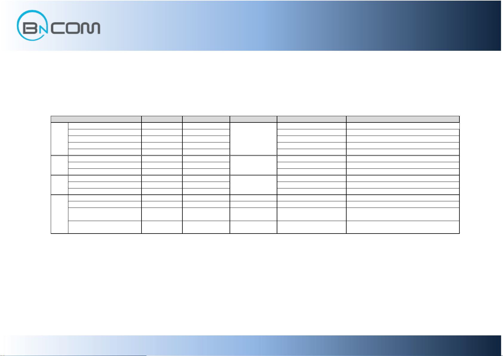
Pin Name Pin No. Pin type Description Note
MODE_SEL 10 Firmware Mode Select
BT_DUT 27 BT DUT
BT_STATUS 9 BT_STATUS
AT_CMD 25 AT Command
RTS_CTL 24
RTS Control
RXD 21
UART Data Input
TXD 19
UART Data Output
nCTS 20
UART Clear to Send Active Low
DEBUG_RX 37
Debug Line Input
DEBUG_TX 34
Debug Line Output
DEBUG_EN 35
Debug Mode Enable, Active Low
3.3V 13,14
Positive Power Supply
nRESET
8 Input, Stong Pull Up Reset
UART_TX
SDA
Function
BAT_P
RST_N
PIO[5]
PIO[14]
PIO[4]
Other
Pins
PIO[24]
Bidirection
Weak Pull Down
UART
Interface
GND
3,4,5,6,15,16,17,29,36,39,
42,43,45,46
UART_TX
PIO[12]
Bideirection,
Weak Pull Down
PIO
PIO[7]
NC
NC
Not Connect
UART_RX
7,11,12,18,22,23,26,28,30
,31,32,33,38,40,41,44
Ground
GROUND
Debug
Interface
UART_RX
Bidirection
Weak Pull Down
1.5 Device Terminal Functions
Revision 1.0 (NOV,2019) 8
Page 9
BT-MSOIII
Bluetooth V5.0
Class1 Data Module
28.00
18.00
0.90
0.50
0.15
1.30
1.95
1.35
5.15
28.00
1.00
1.20
1.50
0.900.50
2.35
1.55
0.15
2.80
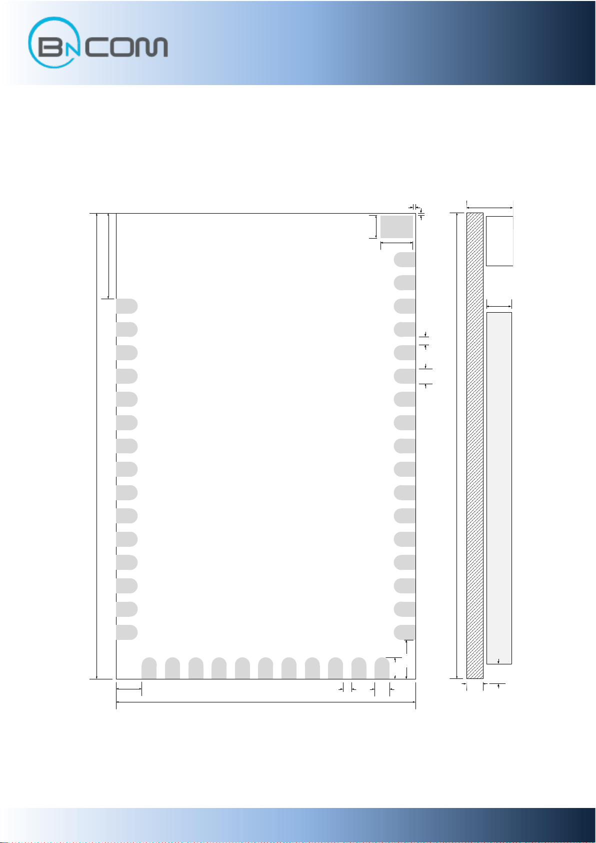
1.6 Package Dimensions & Land Pattern
● unit = mm
● General Tolerances = ±0.2mm
BT-MSOIII Dimensions
Revision 1.0 (NOV,2019) 9
Page 10
BT-MSOIII
Bluetooth V5.0
Class1 Data Module
0.15
1.35
0.40
18.00
28.00
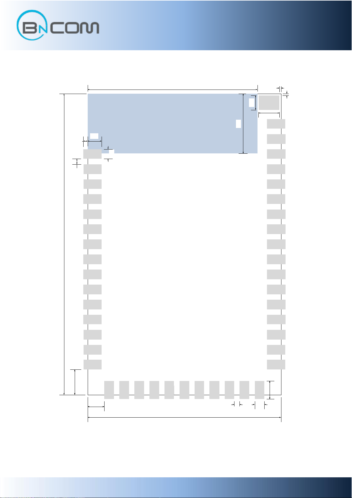
ANTENNA AREA
1.35
0.50
2.35
1.55
1.95
5.56
0.90
15.80
1.30
0.50
0.90
1.70
0.15
Land Pattern
Revision 1.0 (NOV,2019) 10
Page 11
BT-MSOIII
Bluetooth V5.0
Class1 Data Module
Rating
Min
Max
Unit
Storage Temperature range
-40
85
°C
VDD
-0.3
4.4
V
Operating Condition
Min
Typ
Max
Unit
Operating Temperature range
-30
20
85
°C
VDD
2.7
3.3
3.6
V
Classic (Test Condition : VDD =3.3V, Temp = 25°C)
Avr
Peak
Unit
Standby current
-
9.2 - mA
Connected current
-
7.8 - mA
TX current with UART
-
13 mA
RX current with UART
-
11 mA
Input Voltage Levels
Min
Typ
Max
Unit
VIL input logic level low
0
-
0.3xVDD
V
VIH input logic level high
0.7 x VDD
-
VDD+0.4
V
Output Voltage Levels
Min
Typ
Max
Unit
VOL output logic level low, lOL = 4.0mA
- - 0.4
V
VOH output logic level high, lOH = -4.0mA
VDD-0.4
- - V
2. Characteristics
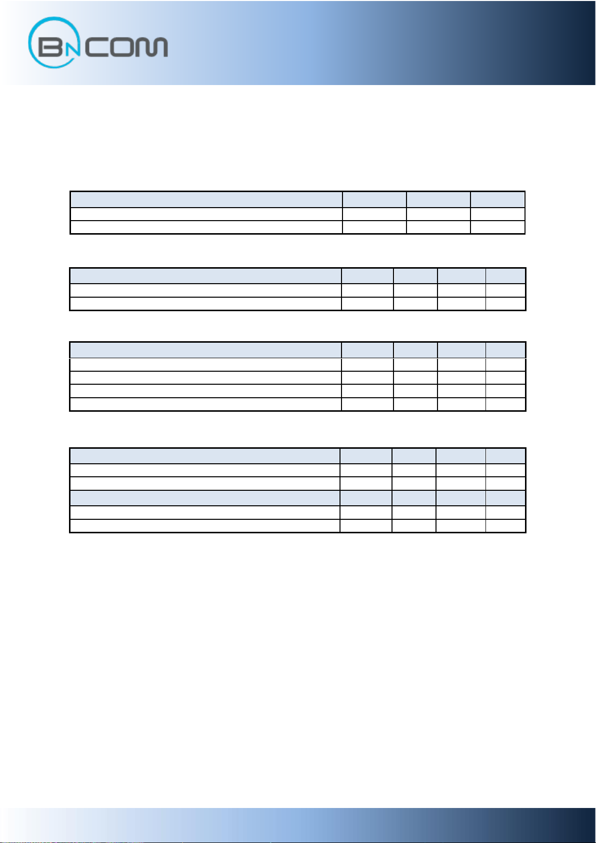
2.1 Electrical Characteristics
■ Absolute Maximum Ratings
■ Recommended Operating Conditions
■ Current consumption
UART baud rate = 230,400bps
■ Digital Terminals
Revision 1.0 (NOV,2019) 11
Page 12
BT-MSOIII
Bluetooth V5.0
Class1 Data Module
RF Specification Condition Min Typ Max Unit
2.402 - 8.86 - dB
2.441 - 9.24 - dB
2.480 - 8.25 - dB
Transmit power density - -6.29 - dBm
Pmin -25.79 - 7.75 dBm
Pst 3.88 4.81 - dB
Frequency Range 2401.515 - 2480.485 Mhz
20dB bandwidth for modulation - 925 - Khz
±2MHz - -22.4 - dBm
±3MHz - -48.09 - dBm
±4Mhz - -48.79 - dBm
Δf1avg - 165 - Khz
Δf2_pass_rate - 100 - %
Δf2avg/Δf1avg - 0.93 -
Intial carrier frequency tolerance df0_avg - -13.7 - Khz
One slot packet(DH1) - -4.7 - KHz
Three slot packet(DH3) - -6.4 - KHz
Five slot packet(DH5) - -6.4 - KHz
2.402 - -84.6 - dBm
2.441 - -86.9 - dBm
2.480 - -86.9 - dBm
Maximum input level -20 -5 - dBm
Receiver
Sensitivity at 0.1% BER for all
basic rate packet types
Transmitter
Output transmit power
Transmit power control
Adjacent channel transmit power
Modulation characteristics
Carrier frequency drift
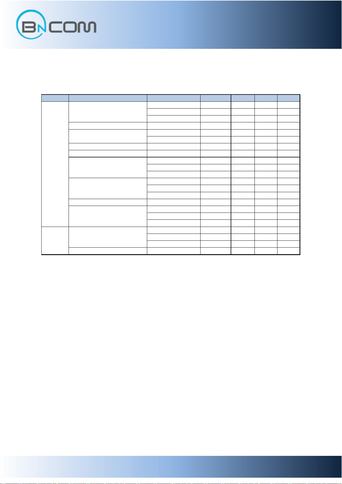
2.2 RF Characteristics
Revision 1.0 (NOV,2019) 12
Page 13
BT-MSOIII
Bluetooth V5.0
Class1 Data Module
Frequency [Mhz]
Efficiency [%]
Average Gain [dBi]
Peak Gain [dBi]
2,400
52.15
-2.83
3.06
2420
58.58
-2.32
3.36
2,450
57.85
-2.38
2.75
2,500
53.68
-2.7
1.64
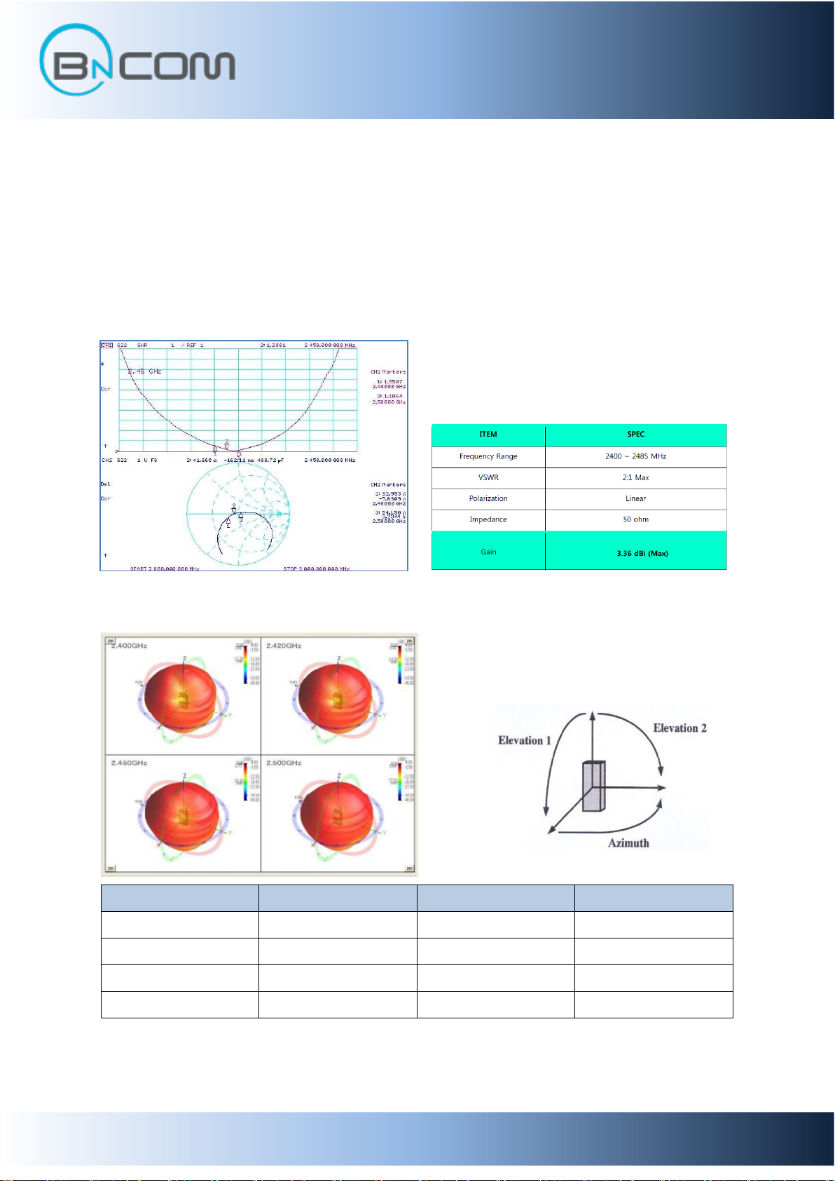
2.3 Antenna Characteristics
The antenna is monopole type of chip antenna. The antenna impedance matching is optimized
for 1 mm ~ 2 mm mother board PCB thickness. The radiation pattern is impacted by the layout of the
mother board. Typically the highest gain is towards GND plane and weakest gain away from the GND
plane.
■ LOG, Smith Chart & VSWR
■ Radiation Gain
Revision 1.0 (NOV,2019) 13
Page 14
BT-MSOIII
Bluetooth V5.0
Class1 Data Module
Configuration Parameters
Supported Values
Data Length
8bit
Flow Control
Hardware RTS/CTS
None
Parity
Even
Odd
None
Number of stop bits
1 or 2
Baud rate
1200
2400
4800
9600
19200
38400
57600
76800
115200
230400
460800
921600
1843200
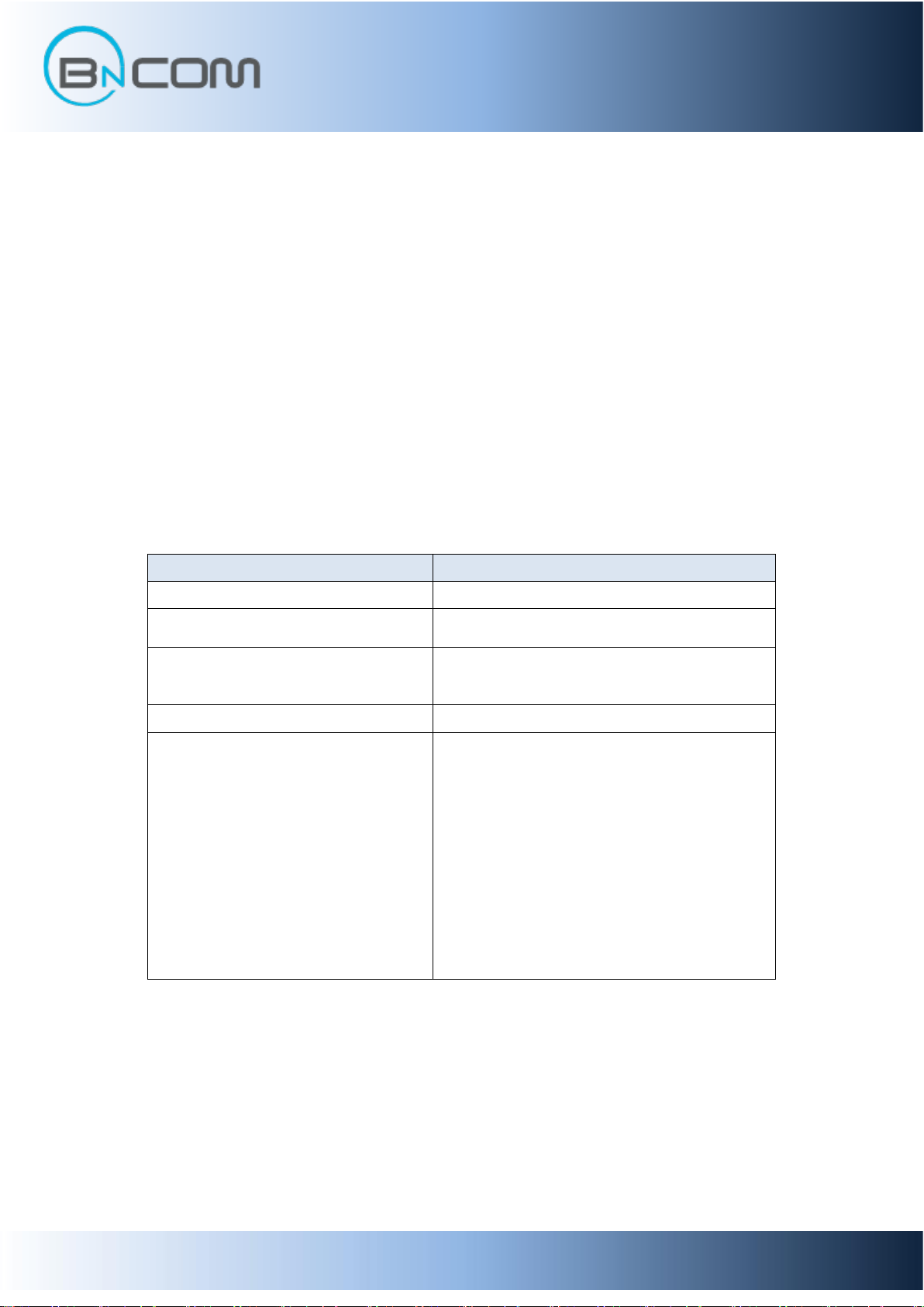
3. Terminal Description
3.1 UART Interface
This is a standard UART interface for communicating with other serial devices.
BT-MSOIII UART interface provides a simple mechanism for communicating with other serial devices using the
RS-232 protocol.
When BT-MSOIII is connected to another digital device, UART_RX and UART_TX transfer data between the 2
devices. The remaining 2 signals, UART_CTS and UART_RTS, implement optional RS232 hardware flow control
where both are active low indicators
3.1.1 Configuration list
Revision 1.0 (NOV,2019) 14
Page 15
BT-MSOIII
Bluetooth V5.0
Class1 Data Module
4. Design Guide
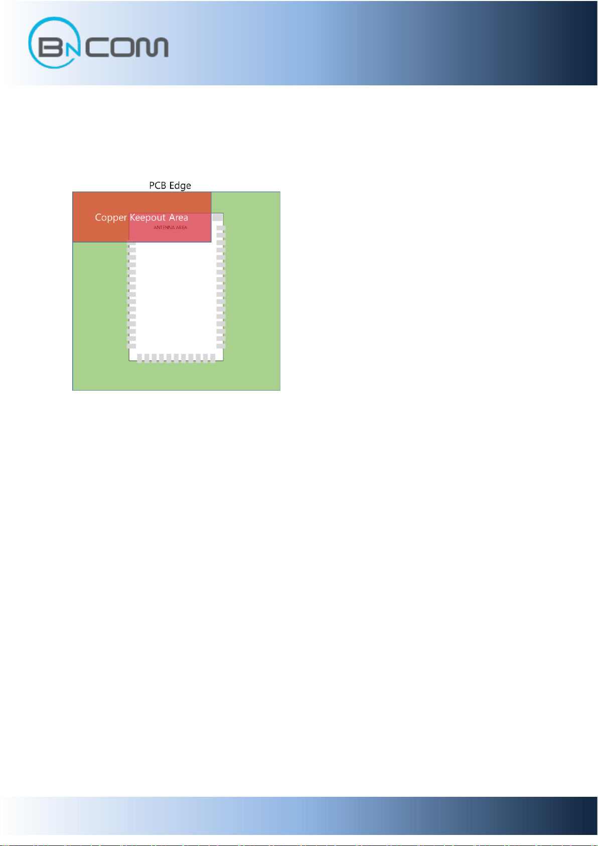
4.1 ANT Placement Guide
For antenna radiation, place the ANT area of the module on the outside of PCB
Or apply a ‘Copper Keepout Area’ as shown.
Revision 1.0 (NOV,2019) 15
Page 16
BT-MSOIII
Bluetooth V5.0
Class1 Data Module
5. Solder Profile
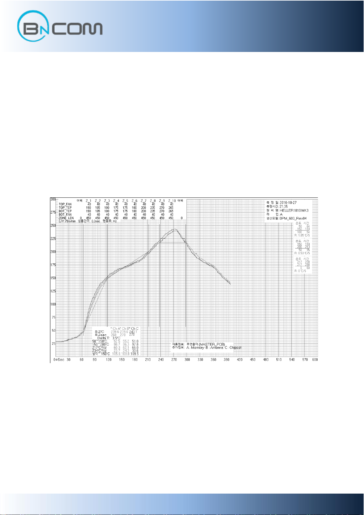
The soldering profile depends on various parameters necessitating a set up for each application. The
data here is given only for guidance on solder re-flow. There are four zones:
1. Preheat Zone - This zone raises the temperature at a controlled rate, typically 1-2.5°C/s.
2. Equilibrium Zone - This zone brings the board to a uniform temperature and also activates the
flux. The duration in this zone (typically 2-3 minutes) will need to be adjusted to optimise the out
gassing of the flux.
3. Reflow Zone - The peak temperature should be high enough to achieve good wetting but not so
high as to cause component discoloration or damage. Excessive soldering time can lead to
intermetallic growth which can result in a brittle joint.
4. Cooling Zone - The cooling rate should be fast, to keep the solder grains small which will give a
longer lasting joint. Typical rates will be 2-5°C/s.
Key features of the profile:
- Initial ramp = 1-2.5°C/sec to 175°C ±25°C equilibrium
- Equilibrium time = 60 to 180 seconds
- Ramp to maximum temperature (245°C) = 3°C/sec max.
- Time above liquidus temperature (217°C): 45-90 seconds
- Device absolute maximum reflow temperature: 260°C
Devices will withstand the specified profile.
Typical Reflow Solder Profile
Revision 1.0 (NOV,2019) 16
Page 17
BT-MSOIII
Bluetooth V5.0
Class1 Data Module
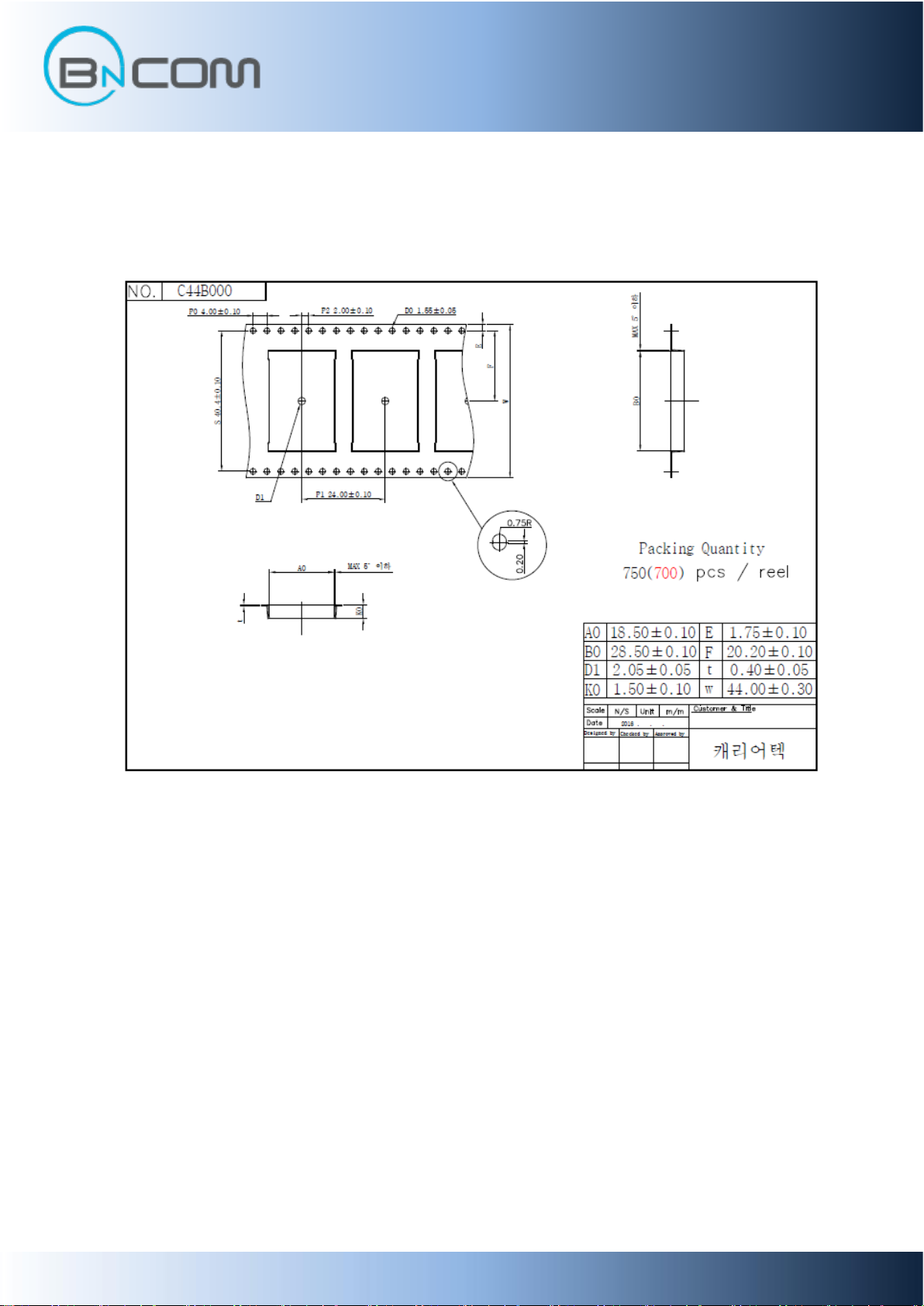
6. Package Information
Revision 1.0 (NOV,2019) 17
Page 18

BT-MSOIII
Bluetooth V5.0
Class1 Data Module
7. Certification note.
7.1 FCC/IC
FCC Information to User
This equipment has been tested and found to comply with the limits for a Class B digital device, pursuant
to Part 15 of the FCC Rules. These limits are designed to provide reasonable protection against harmful
interference in a residential installation. This equipment generates, uses and can radiate radio frequency
energy and, if not installed and used in accordance with the instructions, may cause harmful interference
to radio communications. However, there is no guarantee that interference will not occur in a particular
installation. If this equipment does cause harmful interference to radio or television reception, which can
be determined by turning the equipment off and on, the user is encouraged to try to correct the
interference by one of the following measures:
- Reorient or relocate the receiving antenna.
- Increase the separation between the equipment and receiver.
- Connect the equipment into an outlet on a circuit different from that to which the receiver is
connected.
-Consult the dealer or an experienced radio/TV technician for help.
Caution
THE GRANTEE IS NOT RESPONSIBLE FOR ANY CHANGES OR MODIFICATIONS NOT EXPRESSLY APPROVED
BY THE PARTY RESPONSIBLE FOR COMPLIANCE. SUCH MODIFICATIONS COULD VOID THE USER’S
AUTHORITY TO OPERATE THE EQUIPMENT.
Exposure to Radio Frequency Radiation.
To comply with FCC RF exposure compliance requirements, a separation distance of at least 20 cm must
be maintained between the antenna of this device and all persons.
Any Changes or modifications not expressly approved by the manufacturer could void the user's authority
to operate the equipment.
Attention: Tout changement ou modification non expressément approuvé par le fabricant peut annuler le
droit de l'utilisateur à utiliser l'équipement.
IMPORTANT NOTE : FCC RF Radiation Exposure Statement
This equipment complies with FCC RF radiation exposure limits set forth for an uncontrolled
environment.
This equipment should be installed and operated with a minimum distance of 20 centimeters between the
radiator and your body. This transmitter must not be co-located or operating in conjunction with any other
antenna or transmitter.
This device complies with part 15 of the FCC Rules. Operation is subject to the following two conditions:
(1) This device may not cause harmful interference, and
(2) this device must accept any interference received, including interference that may cause undesired
operation.
Revision 1.0 (NOV,2019) 18
Page 19

BT-MSOIII
Bluetooth V5.0
Class1 Data Module
IC Information to User
This device complies with Industry Canada’s licence-exempt RSSs. Operation is subject to the following
two conditions:
(1) This device may not cause interference; and (2) This device must accept any interference, including
interference that may cause undesired operation of the device
Le présent appareil est conforme aux CNR d’Industrie Canada applicables aux appareils radio exempts de
licence. L’exploitation est autorisée aux deux conditions suivantes :
(1) l’appareil ne doit pas produire de brouillage, et
(2) l’utilisateur de l’appareil doit accepter tout brouillage radioélectrique subi, même si le brouillage est
susceptible d’en compromettre le fonctionnement.
This Bluetooth module has been granted modular approval for mobile applications. OEM integrators for
host products may use the module in their final products without additional FCC / IC (Industry Canada)
certification if they meet the following conditions. Otherwise, additional FCC / IC approvals must be
obtained.
The host product with the module installed must be evaluated for simultaneous transmission
requirements.
The user’s manual for the host product must clearly indicate the operating requirements and conditions
that must be observed to ensure compliance with current FCC / IC RF exposure guidelines.
To comply with FCC / IC regulations limiting both maximum RF output power and human exposure to RF
radiation, use this module only with the included onboard antenna.
A label must be affixed to the outside of the host product with the following statements:
Product Name : Bluetooth Module (Appliance Service Tool)
Contains FCC ID: 2AKMF-BT-MSOIII
Contains IC: 22266-BTMSOIII
The final host / module combination may also need to be evaluated against the FCC Part 15B criteria for
unintentional radiators in order to be properly authorized for operation as a Part 15 digital device.
Revision 1.0 (NOV,2019) 19
 Loading...