

Page 1
INSTRUCTION MANUAL
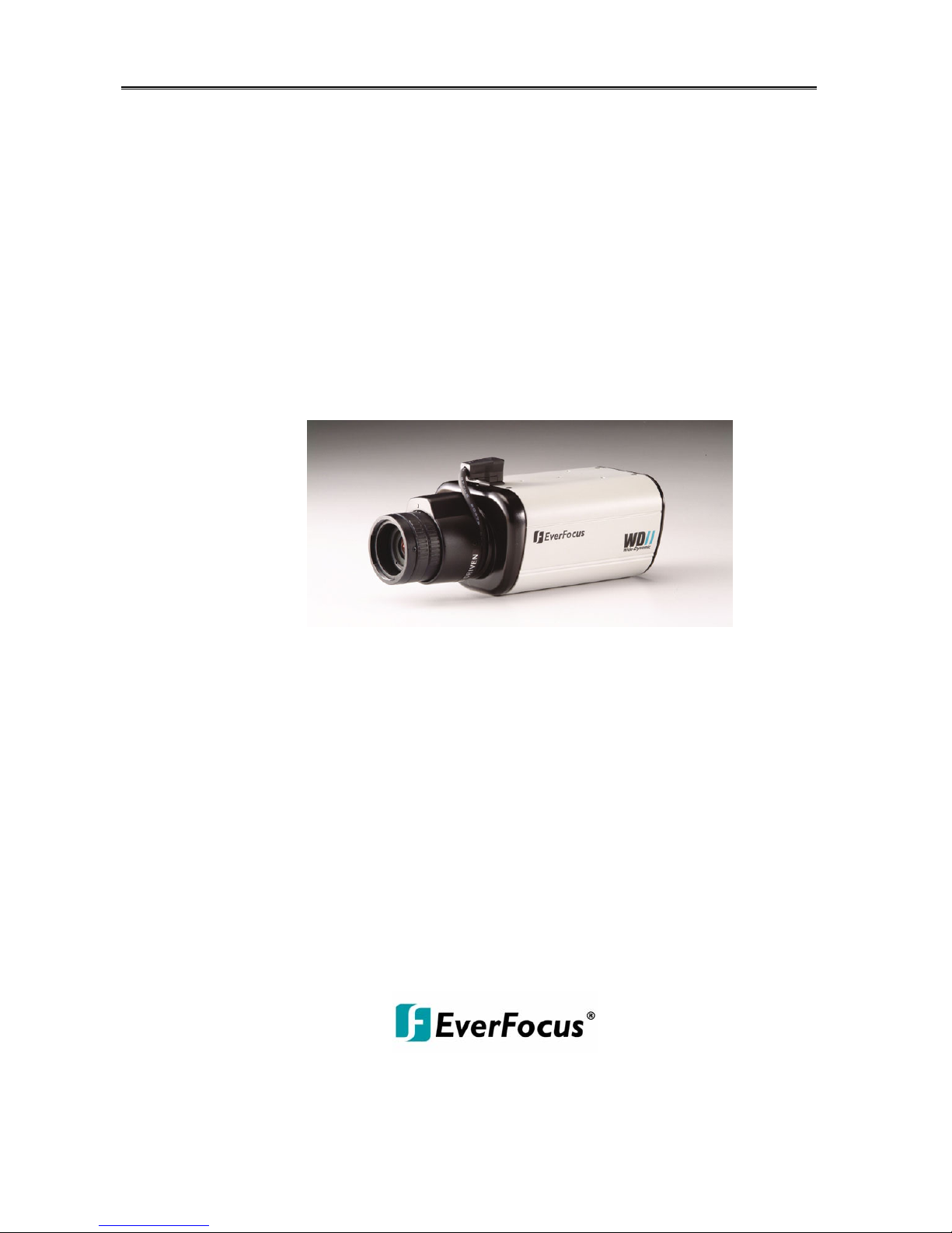
1/3” W-Dynamic High Resolution Color Camera
EQ600 WDII
Version 1.5.5
About this manual
Before installing and using this camera, please read this manual carefully.
Be sure to keep it handy for later reference.
Page 2

Safety Warning
1.Read manual carefully before installing the unit.
Please read this manual first for correct installation and operation.
2.Never install the camera on a ceiling that cannot hold its weight
The product may fall down to cause damages.
3.Do not install the camera near electric or magnetic fields.
Install the camera away from TV, radio transmitter, magnet, electric motor, transformer, audio
speakers because the magnetic fields generated from above devices will distort the video image.
4.Always stop using when the product emits smoke or abnormal heat.
5.Never disassemble the camera nor put impurities in it.
Disassembly or impurities may result in trouble or fire.
6.Never face the camera toward the sun.
Direct sunlight or severe ray may cause fatal damage to sensor and internal circuit.
7.Keep the power cord away from wet and never touch the power cord with wet hands.
Touching the wet power cord with hands or touching the power cord with wet hands may result in
electric shock.
8.Never install the camera in areas exposed to water, oil or gas.
The water, oil or gas may result in failure, electric shock or file.
9.Cleaning-
Do not touch the surface of sensor by hand directly. Use a soft cloth to remove the dirt from the
camera body. Use lens tissue or a cotton tipped applicator and ethanol to clean the sensor and
the camera lens.
10.Do not operate the camera beyond the specified temperature, humidity or power
source ratings.
Use the camera at temperatures within 0°C ~ 40°C and humidity below 90%. The input power
source is DC12V/AC24V.
11.Retain Instructions--The safety and operating instructions should be retained for future reference.
12.Heed Warnings—
All warnings on the unit and in the operating instructions should be adhered to.
Page 3

1
Safety Warning
13.Follow Instructions—
All operating and use instructions should be followed.
14.Cleaning—
Unplug the unit from the outlet before cleaning. Do not use liquid cleaners or aerosol cleaners.
Use a damp cloth for cleaning.
15. Attachments—Do not use attachment not recommended by the product manufacturer as they
may cause hazards.
16. Water and Moisture—
Do not use this unit near water-for example, near a bath tub, wash bowl, kitchen sink, or laundry
tub, in a wet basement, near a swimming pool, in an unprotected outdoor installation, or any area
which is classified as a wet location.
17.Servicing—
Do not attempt to service this unit yourself as opening or removing covers may expose you to
dangerous voltage or other hazards. Refer all servicing to qualified service personnel.
18.Power Cord Protection—
Power supply cords should be routed so that they are not likely to be walked on or pinched by
items placed upon or against them, playing particular attention to cords and plugs, convenience
receptacles, and the point where they exit from the appliance.
19.Object and Liquid Entry—
Never push objects of any kind into this unit through openings as they may touch dangerous
voltage points or short-out parts that could result in a fire or electric shock, never spill liquid of any
kind on the unit.
Notice:The information in this manual was current when published. The manufacturer reserves the
right to revise and improve its products. All specifications are, therefore, subject to change without
notice.
Page 4

2
Table of Contents
1. Product Overview……….………………..……………..………………………….…….…3
1.1 Main Features.…..…………..………………………………………………..…………3
1.2 Content List………………………………………………………………………………3
1.3 Specifications……………..……….……………………………………………………..4
2. Back Panel Connections………………………….………………………….…………….5
3. Operation………………………………………………………..………………..……..…6~7
3.1 Setup Buttons…...………………………………………………………………..……...6
3.2 Display/Close the user setup menu screen…..………………………………………7
4. Main Menu Flow……..…………..………..…………………………………………………8
5. Preset Mode……………..……………………………..…….……………………………9
5.1 Indoor Setup Menu Flow….…………………………………………………………..….9
5.2 Expert Setup………………………………………………………………………………10
6. Camera ID………………………………………………………..………………………12
6.1 Camera ID……………………………………………………………………………….13
6.2 ID Position……………………………………………………………………………….13
6.3 ID Color ………………………………………………………………………………….13
6.4 ID Background…………………………………………………………………………..13
7. Advanced Setup…………………………..…………..…….…………………………14~16
7.1 viewing…………………………………………………………………………….….14
7 .2 Save/restore……………………………………………………………………16
Appendix-A…Camera ID Character patterns………………………………………….……..17
Appendix-B…CCTV References………………………………………..…………………….. 18
Page 5

3
Product Overview
1. Product Overview
By utilizing Digital Pixel System
TM
(DPS) sensor technology, the new EQ600WDII dramatically
improves the performance of surveillance camera in extreme lighting conditions. Where traditional
CCD cameras have difficulty processing images in strong backlighting, the EQ600WDII processes
each pixel independently, correcting for the variations and providing the best possible image under
the lighting conditions.
1.1Main Features
Color DPS ( Digital Pixel System) sensor
High resolution: Over 480 TV Lines/1.0lux and low speed shutter up to 32x
Day/Night function
OSD ( On Screen Display) function control
With programmable camera ID up to 12 characters
Compact stylish design for discrete observation
Image flip capability: Horizontal reverse
1.2Content List
Wide Dynamic Range High Resolution Color Camera unit
User’s manual
Mini Din male connector cable for S-Video / RS-232
Page 6

4
Specifications
1.3
Specifications
Pickup Device 1/3” Color DPS sensor
Picture Element
720(H) × 540(V)
Horizontal Resolution >480 TV lines
Sensitivity 1.0 Lux/ F=1.2 (50IRE color)
Low Speed shutter Up to 32x(2,4,8,16,32)
S/N Ratio >48dB
A
uto exposure: YES
A
uto White Balance Yes, 2500K ~9500K
Back light compensation YES
A
uto IRIS YES
Video Outputs 1.0Vp-p composite S-Video(Y/C output)
A
uto Gain Control Yes
Day/Night function ON/OFF
Dynamic range 95dB typical, 120dB max
Synchronization Internal or Line Lock (AC input required)
Image Flip Yes, Horizontal reverse
Video Output: 1 Vp-p / 75 ohm composite, S-Video (Y/C output)
Imaging System NTSC/ PAL
On Screen Display Yes
Power Source
A
C24V / DC12V
Operating Temperature
0°C ~ 40°C
Power Consumption 7W max.
Dimensions (mm) 56 (W) x 68 (H) x101 (D)
Lens mount C/CS mount, DD Drive
Page 7
5
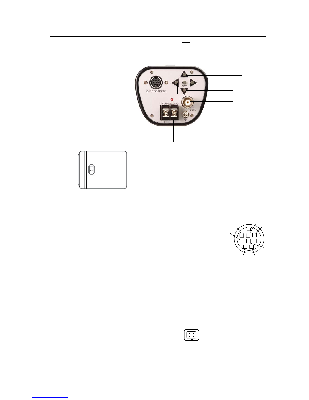
Back Panel Connections
2. Back panel connections
(4)
(8)
(7)
(6)
(1)
(2)
(9)
(1)S-Video / RS-232 port:
Connect Mini Din Male Connector to S-Video / RS-232 port for better video output quality or
communication. Please refer to the pin assignment of the S-Video/ RS-232 port as below:
Please refer to Appendix C for detail RS232 Communication.
(2)AC24V/DC12V Compatible Input Terminal:
This power terminal is for connecting the AC24V/DC12V power supply cord
(3)Video Output Connector:
Connect the video output of the camera to a color monitor or other video devices through a 75 Ohm type coaxial
cable with BNC female connector at backside of the camera.
Y GND
GND
Y
TX
C GND
C
5V
RX
(4) Tact switcher for left cursor
(5) Tact switcher for down cursor
(6) Tact switcher for right cursor
(7) Tact switcher for up cursor
(8) Tact switcher for on-screen setting menu
(9) Auto Iris Lens Connector
This connector is used to connect with the auto iris lens by a 4 pin male connector
Pin 1 Pin 2 Pin 3 Pin 4
3
1
4
2
Direct Drive Cnt- Cnt+ Drv+ Drv-
Page 8

6
Operation
3.Camera Setup Operations
This camera utilizes an On Screen Display (OSD) user setup menu.
3.1 Setup Buttons:
To set items on the user setup menu, use the following buttons on the back panel.
①
Up Button
③Right Button
②Down Button
④Left Button
⑤Set Button
① Up Button: This button is used to move the cursor upwards. Use this button to select an
item or adjust the parameters.
② Down Button: This button is used to move the cursor downwards. Use this button to select
an item or adjust the parameters.
③ Right Button: This button is used to move the cursor to the right. Use this button to select
or adjust the parameters of the select item. The parameter changes each
time as this button is pressed.
④ Left Button: This button is used to move the cursor to the left. Use this button to select or
adjust the parameters of the select item. The parameter changes each time
as this button is pressed.
⑤ Set Button: This button is used to set the determined parameters. If the item has its own
setting menu, press this button to display the setting menu. Press this button for 2 seconds
and the menu screen will appear. Hold this button for another 2 seconds and any writing on
the screen will disappear.
Page 9

7
Operation
3.2 Display/Close the user setup menu screen
SET
Butto
n
Highlighted
600 SERIES MAIN MENU
> PRESETMODE INDOOR..
CAMERA ID OFF
ADVANCED SETUP ..
EXIT MENU
The Cursor Buttons & the SET Button
I. Press the SET button for 2 second
The menu screen will appear on the monitor as the block shown above.
II. Using the cursor button
Use the cursor button c or d to move the cursor up or down. Use the cursor button e or
f to adjust the mode or parameter of settings. The select item will be highlighted with a blue color bar.
III. Switch to sub-menu screens
When the item with sub-menu is selected (highlighted), press the SET button to switch to the sub-menu .
for further settings. Please refer to the figure below.
600 SERIES MAIN MENU
PRESET MODE INDOOR..
CAMERA ID OFF
> ADVANCED SETUP..
EXIT MENU
ADVANCED SETUP
> LENS
WHITE BALANCE..
VIEWING..
SAVE/RESTORE..
PREVIOUS PAGE
Main Menu
Sub-Menu
Note: For those select items with “…” sign in the end, they have the sub-menu for further
settings.
IV. Return to previous page
After setting, use the cursor buttons to select PREVIOUS PAGE, then press the SET
button.
V. Close the menu screen
To close the menu screen, use the cursor button to select EXIT MENU and press the
SET button. Or press the SET button for 1 sec.
Page 10

8
MENU FLOW
4. MAIN MENU FLOW
Each feature in the main menu has its own submenu. You can highlight “INDOOR” under the
“PRESET MODE” feature on the screen, and use the right or left arrows to change the values to
“OUTDOOR”, “LOBBY”, “WAREHOUSE”, “LOBBY”, or “EXPERT”.
ADVANCED SETUP
> LENS
WHITE BALANCE..
VIEWING..
SAVE/RESTORE..
PREVIOUS PAGE
600 SERIES MAIN MENU
>PRESET MODE..
<INDOOR..>
<LOBBY..>
<WAREHOUSE..>
<OUTDOOR..>
<EXPERT..>
600 SERIES MAIN MENU
> PRESETMODE INDOOR..
CAMERA ID OFF
ADVANCED SETUP..
EXIT MENU
600 SERIES MAIN MENU
>CAMERA ID… < OFF>
<ON…>
Page 11

9
MENU
5. PRESET MODE
5.1 INDOOR SET UP
I. You may select the suitable settings from the
preset mode, such as INDOOR, OUTDOOR,
WAREHOUSE, LOBBY or EXPERT based on
the installation environment. Please remember
to use the left and right values to change
parameter.
600 SERIES MAIN MENU
>PRESET MODE <INDOOR..>
<LOBBY…>
<WAREHOUSE>
<OUTDOOR..>
<EXPERT…>
II. Once INDOOR is highlighted, press on the set
key for about 2 seconds.
III. The parameters will be stored as INDOOR
automatically.
600 SERIES MAIN MENU
>PRESET MODE
<<IINNDDOOOORR....>>
<LOBBY..>
<WAREHOUSE..>
<OUTDOOR..>
<EXPERT..>
PRESETS
>CAMERA VIEW SHADOW
SLOW SHUTTER OFF..
METER ZONE NORMAL..
FLUORESCENT OFF
PREVIOUS PAGE..
The CAMERA VIEW feature allows the user to set up the camera for either darker or brighter condition. The
SLOW SHUTTER should be on for a low light area and should be off for a bright area. The METER ZONE
permits the light measurement of a particular area which can be used to determine standard exposure of the
camera. FLUORESCENT should be on only under corresponding light condition. For a detailed explanation of
the above mentioned features, please go to page 11.
Page 12

10
MENU
5.2 EXPERT SET UP
I. You may select the suitable settings, such as
INDOOR, OUTDOOR, WAREHOUSE, LOBBY or
EXPERT based on the installation environment. Please
remember to use the left and right values to change
parameter.
EWD600 MAIN MENU
>PRESET MODE <INDOOR..>
<OUTDOOR..>
<WAREHOUSE>
<LOBBY…>
<EXPERT..>
II. Press the SET button once EXPERT is highlighted
for adjusting the parameters.
III.The parameters will be stored as EXPERT
automatically after changed.
5.1 EXPERT SETUP Menu Flow
5.2 EXPERT SETUP
I. CAMERA VIEW:
T
.
5.2 EXPERT SET UP
I. CAMERA VIEW: The li
EXPERT SETUP
>CAMERAVIEW SHADOW
SLOW SHUTTER OFF
WDR MODE AUTO…
METER MODE NORMAL…
LINELOCK..
AUTO IRIS..
VIEWING..
PREVIOUS PAGE
EXPERT SETUP
>SLOW SHUTTER <OFF>
<ON>
AUTO DYNAMIC RANGE
>BIAS +++++++++
–36 6 36
LIMIT
+++++++++
0 36 36
PREVIOUS PAGE..
NORMAL METER PRESETS
>PRESETS <FULLSCREEN..>
<CENTER>
<LOWER1/3…>
<USER…>
PREVIOUS PAGE…
MANUAL DYNAMIC RANGE
>RANGE +++++++++
0 36 36
PREVIOUS PAGE…
EXPERT SETUP
>WDR MODE <AUTO…>
<MANUAL..>
EXPERT SETUP
>METER MODE <NORMAL…>
<BACKLIGHT…>
BACKLIGHT METER PRESETS
>PRESETS <FULLSCREEN..>
<CENTER>
<LOWER1/3…>
<USER..>
PREVIOUS PAGE..
AUTO IRIS
>DC GAIN
+++++++++
0 120 255
AITHRESHOLD
+++++++++
--42 18 60
PREVIOUS SETUP PAGE…
VIEWING SET UP
BRIGHTNESS 70 100 140IRE
CHROMA
-8 5 8
>GAMMA MODE <MANUAL>
SHARPNESS..
MIRROR OFF
COLORBAR OFF
PREVIOUS PAGE...
SLOW SHUTTER SETUP
> SHUTTER LIMIT 8X
SS PROTERTY COLOR
B/W
SS THRESHOLD +++++++++
28 28 42
EXPERT SETUP
>CAMERA VIEW <SHADOW>
<HIGHLIGHT>
Page 13

11
I. CAMERA VIEW:
The lighting condition of the area where the camera views. SHADOW or HIGHLIGHT.
II. SLOW SHUTTER:
When the setting is OFF, it only operates with AGC in low light condition and keeps the color
image.
When select “ON” then camera will merge into the slow shutter mode in low light condition. User
can set slow shutter limit from 2x ~ 32x and select COLOR or B/W image when slow shutter is
operation by setting SS PROTERTY. Otherwise, user can set the slow shutter start level with SS
THRESHOLD. Setting the parameter smaller let slow shutter start in more highlight condition,
and larger, in more lower light condition
The default SLOW SHUTTER setting is OFF.
.
III. WDR MODE:
The camera offers outstanding Wide-Dynamic Range (WDR) up to 120dB.
Select “AUTO”, the camera will automatically adjust to a suitable Wide Dynamic Range
according to the lighting condition. In “AUTO” mode, the default BIAS is set at “0” but user can
further define the BIAS of WDR. When you feel the contrast of lighting condition is larger,
increase the BIAS. When you feel the contrast is smaller, decrease the BIAS. Under low contrast
condition, set the LIMIT of WDR to a lower value to get better images.
Select “ MANUAL”, user can manually set the Dynamic Range by moving the tag along 0 to 36
level bar. When contrast of lighting condition is larger, increase the number, otherwise
decrease the number towards “0”.
IV. METER MODE:
For setting a frame of the lighting measurement.
Select “ NORMAL” during the normal lighting condition. Choose a suitable frame location, such
as FULLSCREEN, CENTER, LOWER1/3 and USER. If “USER” is selected, there will be a frame
in green color shown on the screen. Use the cursor buttons e f c d to move the location of the
frame, then press SET button. The color of frame will turn to white. Use e f c d buttons to
enlarge the frame size, and press SET button. After resizing, the frame color will turn to red, use
e f c d buttons to shrink the frame size, press SET button to accept the final setting.
Select “ BACKLIGHT” in the strong backlight environment, for example, the lighting condition of
building lobby. Set a suitable location or size of the frame by using the same setting procedures
as “ NORMAL”.
LINELOCK
V PHASE
>V PHASE ++++++++
0 519 624
PREVIOUS PAGE…
LINELOCK SETTING
>LINELOCK <AUTO…>
<OFF>
PREVIOUS PAGE…
Page 14

12
I.AUTO: Set as AUTO LINELOCK mode, it will auto sense the line signal to decision whether running
LINELOCK function or not. Also, user can into the adjustment manual of V PHASE. Use
button e or f to select the V PHASE from 0~624. The larger the V Phase parameter,
the more delay time the LINELOCK.
Note: LI NELOCK is o nly effective while the camera is connected to AC power.
II.OFF:
Set the LINELOCK function off.
MENU
6. CAMERA ID
600 SERIES MAIN MENU
>CAMERA ID < OFF>
<ON..>
ID SETUP
> CAMERA ID _________
ID POSITION UP-LEFT
ID COLOR WHITE
ID BACKGROUND NONE
PREVIOUS PAGE
6.1 CAMERA ID: The camera ID can be turned “ON” to be displayed on the screen, or “OFF”.
The default camera ID is “OFF”.
When “ON” is selected, user can set the Camera ID up to 12 characteres. Use the
cursor button e or f to locate characters (characters will show up in the order ),
press the SET button to choose the character. Use the cursor button f to move to
the next character for setting.
Once the characters of camera ID are all selected, press the SET button for 1 sec
to close the menu and the Camera ID will show on the screen as the figure below.
Ex: CAMERA ID EverFocus101
Page 15

13
6.2 ID POSITION:
There are four positions can be chosen to show the CAMERA ID on the
screen. Choose an ID position that will not cover the import/critical part of
images.
ID SETUP
CAMERA ID ___________
> ID POSITION UP-LEFT
ID COLOR WHITE
ID BACKGROUND NONE
PREVIOUS PAGE
ID POSITION <UP-LEFT>
<UP-RIGHT>
<DOWN-LEFT>
<DOWN-RIGHT>
6.3 ID COLOR
ID SETUP
CAMERA ID EverFocus101
ID POSITION UP-LEFT
> ID COLOR WHITE
ID BACKGROUND NONE
PREVIOUS PAGE
ID COLOR
<WHITE>
<GREEN>
<BLACK>
To make the CAMERA ID more visible on the screen, four colors for the characters
can be chosen.
6.4 ID BACKGROUND
ID SETUP
CAMERA ID ___________
ID POSITION UP-LEFT
ID COLOR WHITE
> ID BACKGROUND NONE
PREVIOUS PAGE
ID BACKGROUND
<WHITE>
<GREEN>
<BLACK>
To make the CAMERA ID more visible on the screen, three background colors can be chosen.
Page 16

14
MENU
7. ADVANCED SET UP:
7.1 VIEWING
MANUAL GAMMA SETUP
> GAMMA +++++++++++++
0.25 0.45 1.00
PREVIOUS PAGE…
VIEWING SETUP
BRIGHTNESS 70 100 140IRE
CHROMA ++++++++++
-8 5 8
> GAMMA MODE <MANUAL…>
SHARPNESS…
MIRROR OFF
COLORBAR OFF
PREVIOURS PAGE…
ADVANCED SETUP
LENS
WHITE BALANCE…
> VIEWING…
SAVE/RESTORE
PREVIOUS PAGE
I.BRIGHTNESS: Use button e or f to adjust the BRIGHTNESS Level from 70 ~140 IRE. The larger
the BRIGHTNESS Level, the brighter the Camera displays.
II.CHROMA:
Adjust the CHROMA saturation level of the video output. The parameter range is from
-8~8. The larger the CHROMA parameter, the stronger the color
III.GAMMA:
There are three modes can be chosen to adjust the GAMMA correction coefficient.
Set “AUTO” for automatically setting the GAMMA correction coefficient.
Select “MANUAL” to adjust the GAMMA correction from 0.25 ~1.0.
Select “OFF” to turn this function off.
Page 17

15
MENU
VIEWING SETUP
BRIGHTNESS 100IRE
CHROMA ++++++++++
-8 5 8
GAMMA MODE AUTO
> SHARPNESS…
MIRROR OFF
COLORBAR OFF
PREVIOURS PAGE…
SHARPNESS
> GAIN +++++++++++
-8 0 8
HORIZONTAL +++++++++++
-8 0 8
HIGH LIGHT APTURE ON
PREVIOUS PAGE…
IV . SHARPNESS:
Adjust the SHARPNESS level of full screen by setting the “GAIN” level from -8 ~8.
Select “ HORIZONTAL” for adjusting H. SHARPNESS only. In the high light environment, select “ HIGH
LIGHT APTURE”, then set “ON” or “OFF”. The larger the SHARPNESS parameter, the sharper the
images.
V. MIRROR:
Select ‘OFF” to show the image as normal. Select “ON” to reflect image horizontally.
Normal Mirror
VI.COLOR BAR:
To confirm the color balance after adjustment, set “ON” to show the COLOR BAR
on the monitor screen, press button f to quit the COLOR BAR. Set “ OFF” for not showing the COLOR
BAR on screen.
Page 18

16
MENU
7.2 SAVE/RESTORE
ADVANCED SET UP
> LENS
WHITE BAL
VIEWING..
> SAVE/RESTORE…
PREVIOUS PAGE
SAVE/RESTORE
> RESTORE USER SETTINGS..
SAVE USER SETTINGS..
RESTORE FACTORY SETTINGS..
RESET CAMERA..
MENU REV. 1.5.5
PREVIOUS PAGE…
I. REST0RE USER SETTINGS
Restore the previous user settings from memory. Press SET button to restore user setting.
II. SAVE USER SETTINGS
Save USER SETTINGS into the camera memory. Press SET button to save user setting.
III. RESTORE FACTORY SETTINGS
Restore the default setting. Press SET button to restore factory setting. Please refer to the Appendix-B
for the default factory settings.
IV. RESET CAMERA
Restart the camera again. Press SET button to reset camera.
VI.MENU REV.1.5.5
Display the software version.
Page 19

Appendix-A
CAMERA ID Character patterns
Page 20

18
Appendix-D
CCTV References:
Chroma: That quality of color which embraces both hue (Corresponds to colors such as red, blue,
etcetera) and saturation. White, black, and grays have no chroma.. Increasing the chroma level
will brighten up certain colors on the camera picture.
Color Temp: The white light is made up of all wavelengths in the visible spectrum. True white light has an
equal intensity at every wavelength. If any wavelength has a higher intensity than the rest, the
light takes on a hue related to the dominant wavelength. A simple definition of the hue cast of
white light is called “Color Temperature”. The one standard white lighting in photography
and photomicrography is 5000°K (D50) and is called daylight neutral white.
dB: Basically, a measure of the power ratio of two signals. In system use, a measure of the voltage
ratio of two signals, provided they are measured across a common impedance.
Dynamic Range: The difference between the maximum acceptable signal level and the minimum acceptable
signal level. Wide dynamic range enables the camera to adjust to a variety of lighting
conditions in an efficient manner.
Gamma: A numerical value, or the degree of contrast in a television picture, which is the exponent of
that power law which is used to approximate the curve of output magnitude versus input
magnitude over the region of interest. Gamma level can be manipulated to make the picture
more human eye perceptible.
Iris: An adjustable aperture built into a camera lens to permit control of the amount of light passing
through the lens.
Line Lock: Refers to multiple cameras being powered by a common AC (alternative current) source and
consequently have field frequencies locked to their same AC source frequency.
Lux: International System (Sl) unit of illumination in which the meter is the unit of length.
Resolution (horizontal): The amount of resolvable detail in the horizontal direction in a picture. It is usually
expressed as the number of distinct vertical lines, alternately black and white, which can be
seen in a distance equal to picture height.
Resolution (vertical): The amount of resolvable detail in the vertical direction in a picture. It is usually
expressed as the number of distinct horizontal lines, alternately black and white, which can
theoretically be seen in a picture.
S/N Ratio: The Signal-to-Noise ratio between useful television signal and disturbing noise or show
Page 21

19
EverFocus Electronics Corp.
Head Office
12F, No.79, Sec.1, Shin-Tai Wu Road,
Hsi-Chi, Taipei Hsien,
Taiwan
Tel:886-2-26982334
Fax:886-2-26982380
e-mail:
marketing@everfocus.com.tw
Website: http://www.everfocus.com.tw
USA Office
2445 Huntington Drive,
San Marino, CA 91108,
U.S.A.
Tel: (626)844-8888
Fax:(626)844-8838
e-mail:
info@everfocus.com
Website: http://www.everfocus.com
Beijing Office
Room 609, Technology Trade Building,
ShangDi Haidian , Beijing, China
Tel: (010)62973336/37/38/39
Fax: (010)62971423
E-mail:
marketing@everfocus.com.cn
Germany Office
Albert-Einstein-Strasse 1,
D-46446 Emmerich,
Germany
Tel: 49-2822-93940
Fax: 49-2822-939495
e-mail:
info@everfocus.de
Website:
http://www.everfocus.de
Japan Office
1809 WBG Maribu East 18F, 2-6 Nakase,
ihama-ku, Chiba city 261-7118, Japan
Tel: 81-43-212-8188
Fax: 81-43-297-0081
MWD6G0010A
 Loading...