

EverFocus POLESTAR EHN7221, POLESTAR EHN7260, POLESTAR EHN7360 User Manual
Star Light Outdoor Dome IR Network Camera
EHN7221/7260/7360
Ultra Low Light Network Camera
User’s Manual
Copyright © EverFocus Electronics Corp.
Release Date: March, 2016

Copyright 1995-2016 EverFocus Electronics Corp.
All rights reserved. No part of the contents of this manual may be reproduced or transmitted in any form or by
any means without written permission of the EverFocus Electronics Corporation.
EverFocus
12F-1, No.79, Sec. 1, Shin-Tai Wu Road,
Hsi-Chih, New Taipei City, Taiwan
TEL: +886 2 2698 2334
FAX: +886 2 2698 3943
www.everfocus.com.tw
March, 2016

About this document
All the safety and operating instructions should be read and followed before the unit is operated. This
manual should be retained for future reference. The information in this manual was current when
published. The manufacturer reserves the right to revise and improve its products. All specifications are
therefore subject to change without notice.
Regulatory Notices
FCC Notice "Declaration of Conformity Information"
This equipment has been tested and found to comply with the limits for a Class
A digital device, pursuant to part 15 of the FCC Rules. These limits are designed to provide reasonable
protection against harmful interference in a residential installation. This equipment generates, uses and
can radiate radio frequency energy and, if not installed and used in accordance with the instructions,
may cause harmful interference to radio communications. However, there is no guarantee that
interference will not occur in a particular installation. If this equipment does cause harmful interference
to radio or television reception, which can be determined by turning the equipment off and on, the user
is encouraged to try to correct the interference by one or more of the following measures:
- Reorient or relocate the receiving antenna.
- Increase the separation between the equipment and receiver.
- Connect the equipment into an outlet on a circuit different from that to which the receiver is
connected.
- Consult the dealer or an experienced radio/TV technician for help.
Warning: Changes or modifications made to this equipment, not expressly approved by EverFocus or
parties authorized by EverFocus could void the user's authority to operate the equipment.
This device complies with part 15 of the FCC Rules. Operation is subject to the following two conditions:
(1) This device may not cause harmful interference, and
(2) This device must accept any interference received, including interference that may cause undesired
operation.
EverFocus Electronics Corp.
12F-1, No. 79, Sec. 1, Shin-Tai Wu Rd.,
Hsi-Chi, New Taipei City, Taiwan
The POLESTAR Series camera complies with CE and FCC.
i

Precautions
1. Do not install the camera near electric or magnetic fields.
Install the camera away from TV/radio transmitters, magnets, electric motors, transformers and
audio speakers since the electromagnetic fields generated from these devices may distort the video
image or otherwise interfere with camera operation.
2. Never disassemble the camera beyond the recommendations in this manual nor introduce
materials other than those recommended herein.
Improper disassembly or introduction of corrosive materials may result in equipment failure or other
damage.
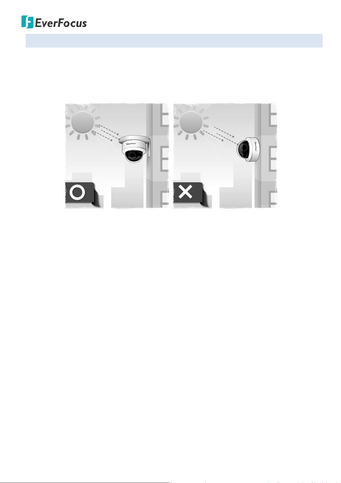
3. Try to avoid facing the camera toward the sun.
In some circumstances, direct sunlight may cause permanent damage to the sensor and/or internal
circuits, as well as creating unbalanced illumination beyond the capability of the camera to
compensate.
4. Keep the power cord away from water and other liquids and never touch the power cord with wet
hands.
Touching a wet power cord with your hands or touching the power cord with wet hands may result in
electric shock.
5. Never install the camera in areas exposed to oil, gas or solvents.
Oil, gas or solvents may result in equipment failure, electric shock or, in extreme cases, fire.
6. Cleaning
For cameras with interchangeable lenses, do not touch the surface of the sensor directly with the
hands. Use lens tissue or a cotton tipped applicator and ethanol to clean the sensor and the camera
lens. Use a damp soft cloth to remove any dirt from the camera body. Please do not use complex
solvents, corrosive or abrasive agents for cleaning of any part of the camera.
7. Do not operate the camera beyond the specified temperature, humidity or power source ratings.
Use the camera at temperatures within -40°C ~ 55°C / -40°F ~ 131°F (12VDC); -20°C ~ 55°C / -4°F ~
131°F (PoE), and humidity between 20% and 80%; this device is not rated as submersible. The input
power source is 12VDC / 24VAC~ / PoE. Be sure to connect the proper + / - polarity and voltage, as
incorrect polarity or too high a voltage will likely cause the camera to fail, and such damage is not
covered by the warranty. The use of properly fused or Class 3 power limited type supplies is highly
recommended.
8. Mounting
Use care in selecting a solid mounting surface which will support the weight of the camera plus any
wind, snow, ice or other loading, and securely attach the camera to the mounting surface using
screws and anchors which will properly support the camera. If necessary (e.g. when mounting to
drop ceilings) use a safety wire to provide additional support for the camera.
ii

CONTENTS
1. Introduction .................................................................................................................................... 1
2. Physical Description ....................................................................................................................... 2
2.1. Dimensions ....................................................................................................................................... 2
3. Features ........................................................................................................................................... 3
4. Installation ...................................................................................................................................... 4
4.1. Packing List ....................................................................................................................................... 4
4.2. Optional Accessory .......................................................................................................................... 5
4.3. Terminal Block .................................................................................................................................. 6
4.4. Important Notice for the Installation ............................................................................................... 7
4.5. Basic Installation .............................................................................................................................. 8
5. Accessing the User Interface ...................................................................................................... 13
5.1. Checking the Dynamic IP Address .................................................................................................. 13
5.2. Settings for Microsoft Internet Explorer ........................................................................................ 17
5.3. Connecting the Camera to the Network ........................................................................................ 18
5.4. Live View Window .......................................................................................................................... 20
6. Playback ......................................................................................................................................... 26
6.1 Remote Playback Using Playback Page .......................................................................................... 26
6.2 Setting up the Playback Function ................................................................................................... 28
6.2.1 Inserting / Removing the micro SD Card ........................................................................... 28
6.2.2 Testing the Playback Function ........................................................................................... 29
7. Settings .......................................................................................................................................... 31
7.1. System Settings .............................................................................................................................. 32
7.1.1. Network ............................................................................................................................. 32
7.1.2. Date / Time ........................................................................................................................ 38
7.1.3. Storage .............................................................................................................................. 39
7.1.4. Display and Overlay ........................................................................................................... 41
7.1.5. System Maintenance ......................................................................................................... 43
7.1.6. System Information ........................................................................................................... 46
7.1.7. User ................................................................................................................................... 47
7.1.8. Black / White List ............................................................................................................... 49
7.1.9. Serial Communication ....................................................................................................... 50
7.2. Camera Settings ............................................................................................................................. 51
7.2.1. Streaming and Audio ......................................................................................................... 51
iii

7.2.2. Profile ................................................................................................................................ 54
7.2.3. Camera .............................................................................................................................. 55
7.2.4. Schedule ............................................................................................................................ 59
7.2.5. Image ................................................................................................................................. 60
7.3. Event Settings ................................................................................................................................. 62
7.3.1. Event Wizard...................................................................................................................... 62
7.3.2. Event .................................................................................................................................. 63
7.3.3. Notification ........................................................................................................................ 68
7.4. Link to Smart Phone App ............................................................................................................... 71
8. Upgrading Firmware Using IP Utility ......................................................................................... 72
9. Specifications ................................................................................................................................ 74
10. Troubleshooting ......................................................................................................................... 76
Appendix ............................................................................................................................................ 81
A. Tested Card Brands ......................................................................................................................... 81
B. Enabling the Multicast Function .................................................................................................... 82
C. RTSP URL Syntax ............................................................................................................................. 84
D. Setting up Port Forwarding Function ............................................................................................. 85
E. Setting up DDNS Function .............................................................................................................. 87
iv

EHN7221/7260/7360
•
1. Introduction
The POLESTAR Series outdoor IP dome camera deliveries image quality of up to 3MP. Equipped with an
auto focus lens, the series can provide the desired field of view with superior video quality in precision
focus. Adopted with a Sony 1/2.8” CMOS image sensor, the high sensitivity characteristics enables the IP
camera to perform clear color images with less image noise even in the starlight or moonlight environment.
Equipped with a P-Iris, the IP cameras are capable of controlling the best iris position automatically and
precisely in varying lighting conditions, expanding the focus area of the images and meanwhile improve the
image sharpness. The IP camera also supports dual streams from H.265, H.264 or MJPEG compression
formats.
The POLESTAR Series outdoor IP dome camera has a built-in micro SDHC card slot. Except 12VDC and
24VAC~ power supply, the IP camera also supports Power over Ethernet (IEEE802.3af). Featured with a
weather-proof (IP68) and vandal-proof (IK10) housing, the IP cameras meet a wide variety of needs for
outdoor surveillance.
The POLESTAR Series outdoor IP dome camera conforms to ONVIF for compatibility with other network
video devices. You can also use EverFocus Mobile applications to remotely view the live views of the
cameras through your iOS or Android handheld devices; or use EverFocus CMS to remotely manage
multiple IP devices connected on the network.
The POLESTAR Series outdoor IP dome camera Models
Model Name Megapixel Max. Video Resolution Frame Rate
EHN7221 2 MP 1920 x 1080 Dual streams: 60fps @ 1080p; 30fps @ VGA
EHN7360 3 MP 2048 x 1536 30fps
EHN7260 2 MP 1920 x 1080 30fps
System Requirement
Before installing, please check that your computer meets the following system requirements.
Operating System Windows 7 (32 and 64-bit) or above
CPU
Intel Core i5 CPU @ 2.0GHz (or equivalent AMD) or higher
(Intel Core i7 CPU @ 3.4GHz recommended)
Graphic Card 512MB RAM graphic cards (or equivalent on-board graphic cards)
2GB or more (8GB recommended)
RAM
• Additional HD space depends on required local storage of video files,
100 Mbps network card.
• DirectX 9.0c
Software
• Internet Explorer 9 and later, Firefox 4.0-9.0, Chrome (Windows
version 44 and earlier)
Note: For using the Internet Explorer, some settings are required. Please refer to 5.2 Settings for
Microsoft Internet Explorer.
1
EHN7221/7260/7360
8
2
Camera Module
1
7
4
3
6
5
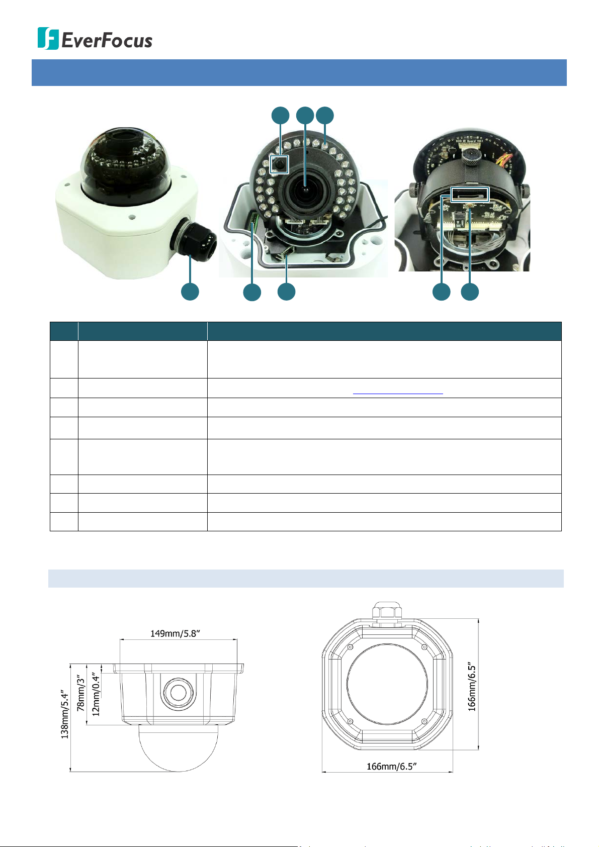
2. Physical Description
No. Item Name Descriptions
1 Cable Gland
Equipped with three plugs inserted in the cable conduits for
waterproofing.
2 Terminal Block A 16-pin terminal block. See 4.3 Terminal Block.
3 LAN / PoE Connect to a 10/100 Ethernet or PoE.
4 Micro SD / SDHC Slot Insert a micro SD / SDHC card (see Appendix for tested card brands).
Press and hold the Reset Button for 10 seconds to reset all
5 Reset Button
configurations to the factory default settings.
6 IR LEDs 33 IR LEDs for infrared illumination in night vision applications.
7 Lens Vari-focal lens, Auto Focus, 3.3-10mm, F1.3, P-IRIS.
8 Light Sensor Detects lights.
2.1. Dimensions
2

EHN7221/7260/7360
3. Features
• 1/2.8” SONY progressive CMOS image sensor delivers high resolution, and supports both H.265
and H.264 in full frame rate
• One push auto focus for remote image adjustment
• P-IRIS lens with a stepping motor for exact positioning to improve the IRIS performance
• Dual Streams from H.265, H.264 and M-JPEG
• Ultra low light
• Corridor Format
• True Day/Night function
• 3D Noise Reduction for Low-light Conditions (3DNR)
• Extended IR range of up to 30M / 98.4ft. with 33 LEDs
• Smart IR function eliminates overexposure problems
• Wide dynamic range function (WDR)
• Two-way audio
• Defog function supported
• RS-485 supported
• Alarm I/O supported
• Micro SD card supported
• Triple power inputs supported: PoE / 12VDC / 24VAC~
• IP68 water proof and IK10 vandal resistance
• EverFocus MobileFocus / MobileFocus Plus apps (iOS and Android) supported
• EverFocus Genie XMS CMS supported
• ONVIF profile S compliant
3

EHN7221/7260/7360
EverFocus office or agents for more information. Please also keep the shipping carton for possible
4. Installation
4.1. Packing List
Please check that there is no missing item in the package before installing.
• EHN Series Camera x 1 • Desiccant Bag x 2
• MAC Address Sticker x 2 • Power Pigtail Cable x 1
• Plastic Bag x 1 (which contains the below items) • Torx Screwdriver x 1
- Hexagon Screw x 4
- Phillips Screw x 4
- Screw Anchor x 4
- Rubber Ring x 1 (replace the old rubber ring around
the lens only when it is damaged)
• RJ-45 Connector x 1
• Base Plate x 1
• Inner Paper x 1
• Software CD x 1
• Quick Installation Guide x 1
Note:
1. Equipment configurations and supplied accessories vary by country. Please consult your local
future use.
2. Contact the shipper if any items appear to have been damaged in the shipping process.
4
EHN7221/7260/7360
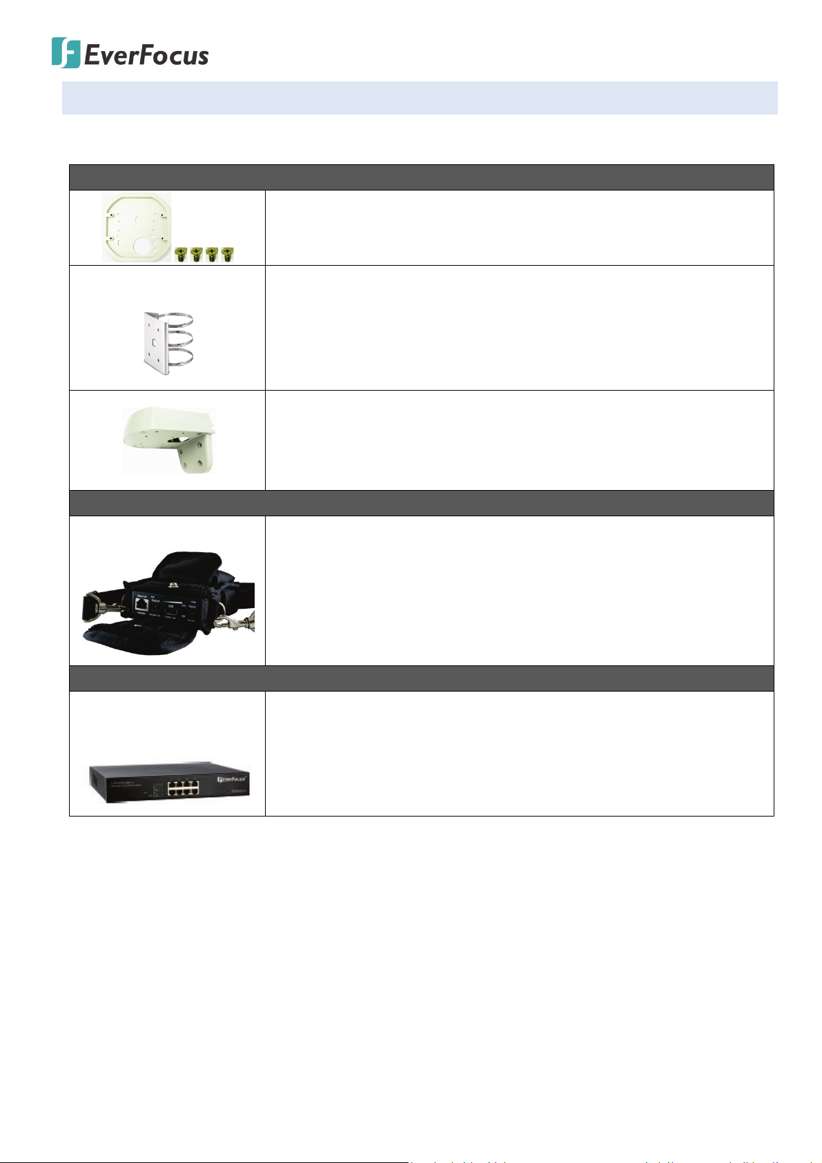
4.2. Optional Accessory
You can use the optional accessories to expand the capabilities and versatility of the camera. Please
contact your dealer for more information.
Brackets
One Adapter Plate with 4 Screws
The Adapter Plate is designed for wiring the cables through the bottom
of the camera case.
• EPTZ-PLM
IP Sidekick
• IP Sidekick - ESK1000
PoE Switch
Pole Mount Bracket
Dimensions:
Ф155mm / 6.1” (max)
Ф90mm / 3.54” (min)
Stainless Steel
L-Shaped Mounting Bracket
To prevent the camera from being damaged by direct sunlight, it is
strongly recommended to use the L-Shaped Mounting Bracket to mount
the camera to the wall.
Using it for installation, you do not need to pre-configure the IP address
or to use an additional monitor to check and adjust all the IP cameras.
The product can assign an IP address to the camera, then you can
connect and check the camera live view using EverFocus mobile App EF
Sidekick. For details about IP Sidekick, please refer to the IP Sidekick –
ESK1000 User’s Manual.
• EverFocus 5 / 8 / 16 /
24 Ports PoE Switch
5 Ports: ES0501-40
8 Ports: ES0812-31 / ES0802-41
16 Ports: ES1625-31 / ES1645-51
24 Ports: ES2426-31 / ES2446-51 / ES2448-62
5
EHN7221/7260/7360
3 2 16 5 49 8 712 11 1016 15 14 13
Camera Module
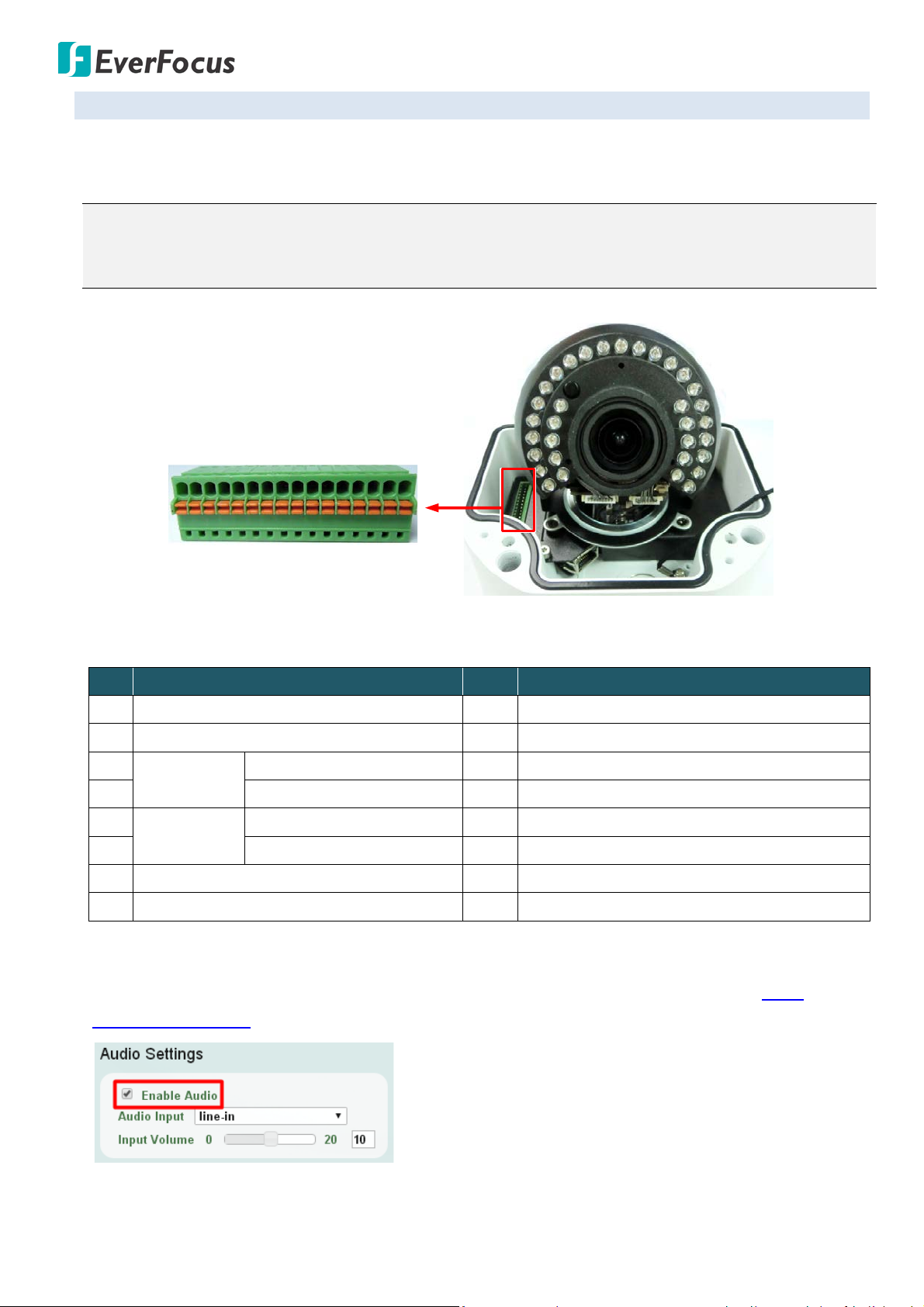
4.3. Terminal Block
The I/O terminal block, located on the camera module, can be used to develop applications for alarm
input and output, two-way audio, TV-output or a variety of other functions.
Note:
1. You can unplug the terminal block from the camera module for easier wiring.
2. Microphones and speakers with a (built-in) amplifier and external power supply are required.
Pin Assignment
No. Functions No. Functions
1 12 VDC Input 9 Audio Output (Line-out)
2 Digital GND 10 Audio GND
3
Alarm Output (+) 11 CVBS Output
Alarm Out
4 Alarm COM (-) 12 Digital GND
5
Alarm Input (+) 13 AC24V+
Alarm In
6 Digital GND (-) 14 AC24V-
7 Audio Input (Line-in) 15 RS485_A
8 Audio GND 16 RS485_B
To activate the Audio function, the Enable Audio must be checked. See Audio Settings in 7.2.1
Streaming and Audio.
6
EHN7221/7260/7360
4.4. Important Notice for the Installation
If you want to mount the camera on the wall where direct sunlight may occur, it is strongly
recommended to mount the camera using the L-Shaped Mounting Bracket to prevent the camera from
being damaged by direct sunlight. Please refer to the Quick Installation Guide of L-Shaped Mounting
Bracket for more details.
7
EHN7221/7260/7360
Base Plate
Wiring Box
Circle Plate
Camera Case
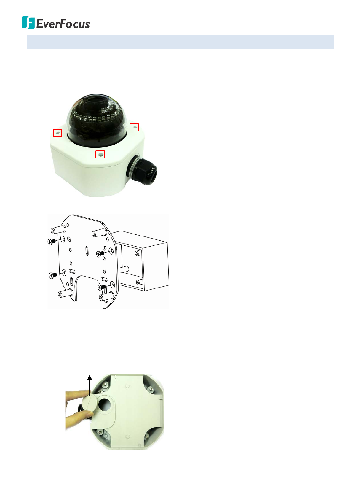
4.5. Basic Installation
Follow the steps below to install the EHN IP camera to the wall.
To mount the camera to the wall and connect the cables to the related devices:
1. Unscrew the four screws and remove the cover from the camera.
2. Screw the Base Plate to the Wiring Box using the supplied four Phillips Screw.
If you want to wire the cables through the bottom of the Camera Case, follow the steps below:
a. Remove the Circle Plate on the bottom of the Camera Case. You can simply loosen the Circle
Plate using a coin.
8
EHN7221/7260/7360
Cable Gland
Camera Case
Base Plate
Wiring Box
Adapter Plate
Base Plate
Camera Case
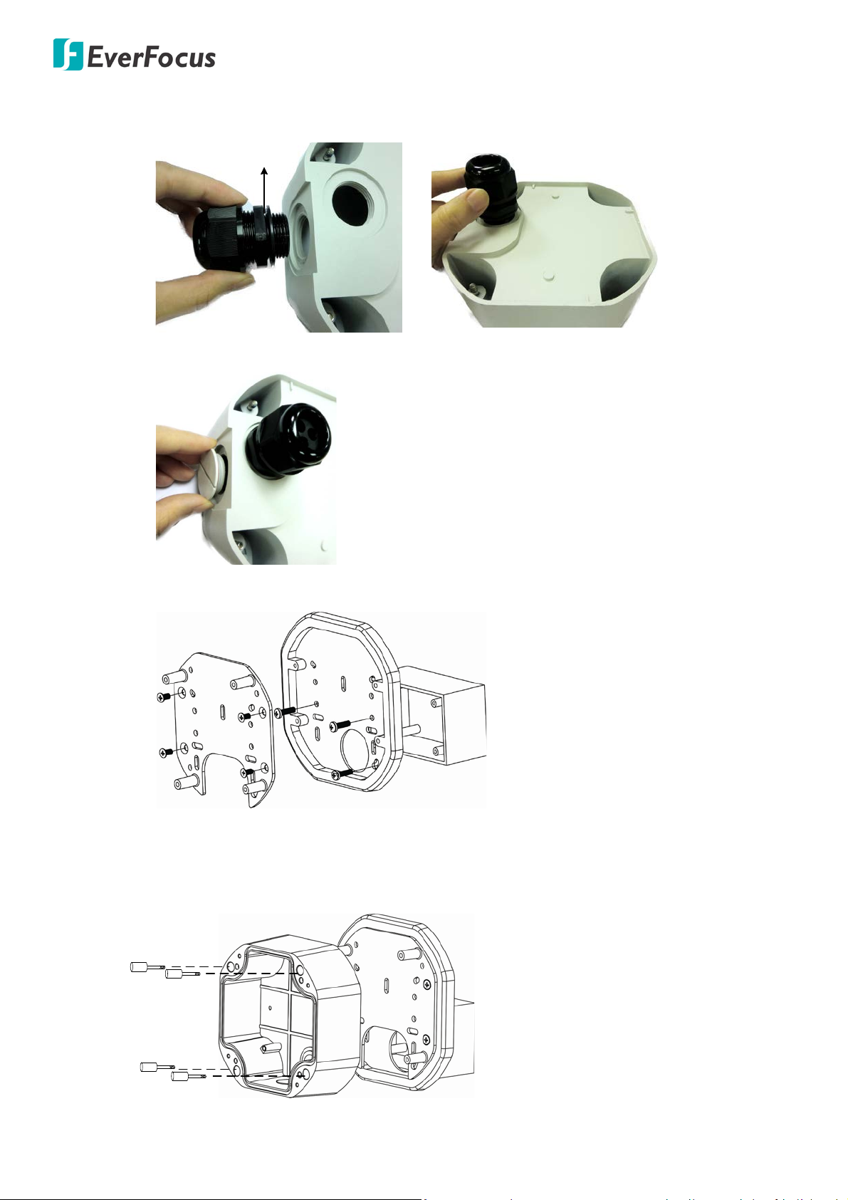
b. Loosen and remove the Cable Gland from the Camera Case. Screw the Cable Gland to the
hole on the bottom of the Camera Case.
c. Screw the Circle Plate to the side hole on the Camera Case.
d. Screw the Adapter Plate between the Base Plate and Wiring Box.
3. Screw the Camera Case back to the Base Plate using the supplied four Hexagon Screws.
9
EHN7221/7260/7360
Screw BodyScrew Cap
Stopper Claw
Plug
Stopper
Adjustment Ring(s)
Cable Gland Cable Gland
Screw Cap
Plug
Stopper
Cable Conduit
Slitted Cable Conduit
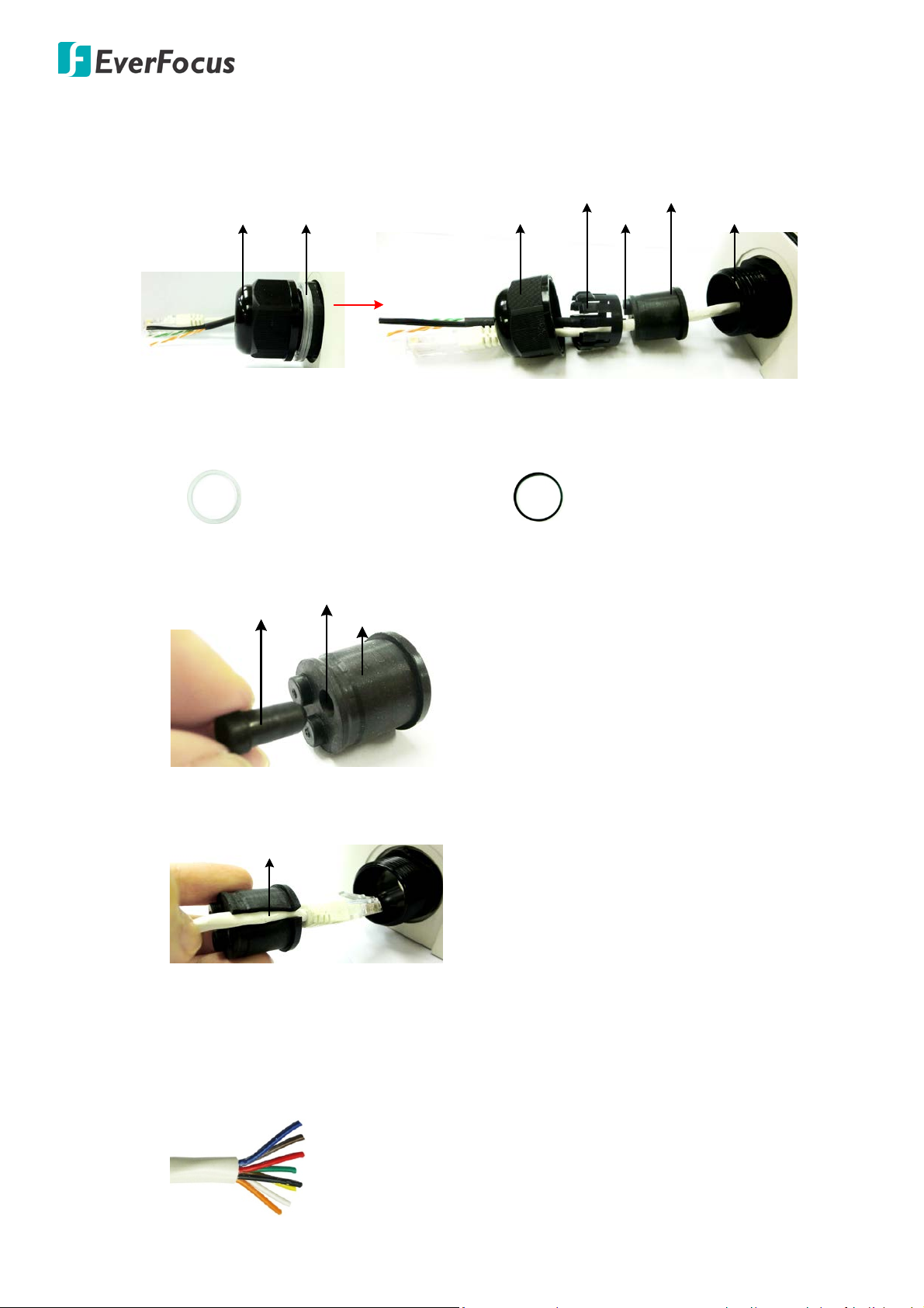
4. Insert the network / PoE cable or the additional cables through the Cable Gland. Up to three
cables can be inserted. Note that except the network / PoE cable, additional wires have to be
bundled into a cable with diameter ranging from 5.3mm to 6.4mm (see Steps below).
a. Keep the supplied 6 Adjustment Rings for waterproofing.
• Transparent x 5 (1 mm thickness)
• Black x 1 (0.5 mm thickness)
b. Remove the Plug(s) from the Stopper (depends on the number of cables inserted). One
Cable Conduit can only be inserted with one cable.
c. Insert the network / PoE cable through the Cable Conduit, if your network / PoE cable
already has a RJ-45 connector, then you can use the Slitted Cable Conduit.
d. Optionally insert the additional wires, such as power (if you want to power the camera
through a 12 VDC power source), alarm and audio cables, through the other Cable Conduit.
Note that one Cable Conduit can only be inserted with one cable. The Cable Conduit has
been tested to support cable diameter between 5.3mm and 6.4mm. Please refer to the
image below to bundle the lose wires before inserting to the Cable Conduit.
10
EHN7221/7260/7360
e. Tighten the Screw Cap all the way to the Adjustment Ring(s).
Due to the variable cable diameters, for better waterproofing, it is strongly recommended
that you apply silicon sealants to the inner Screw Cap.
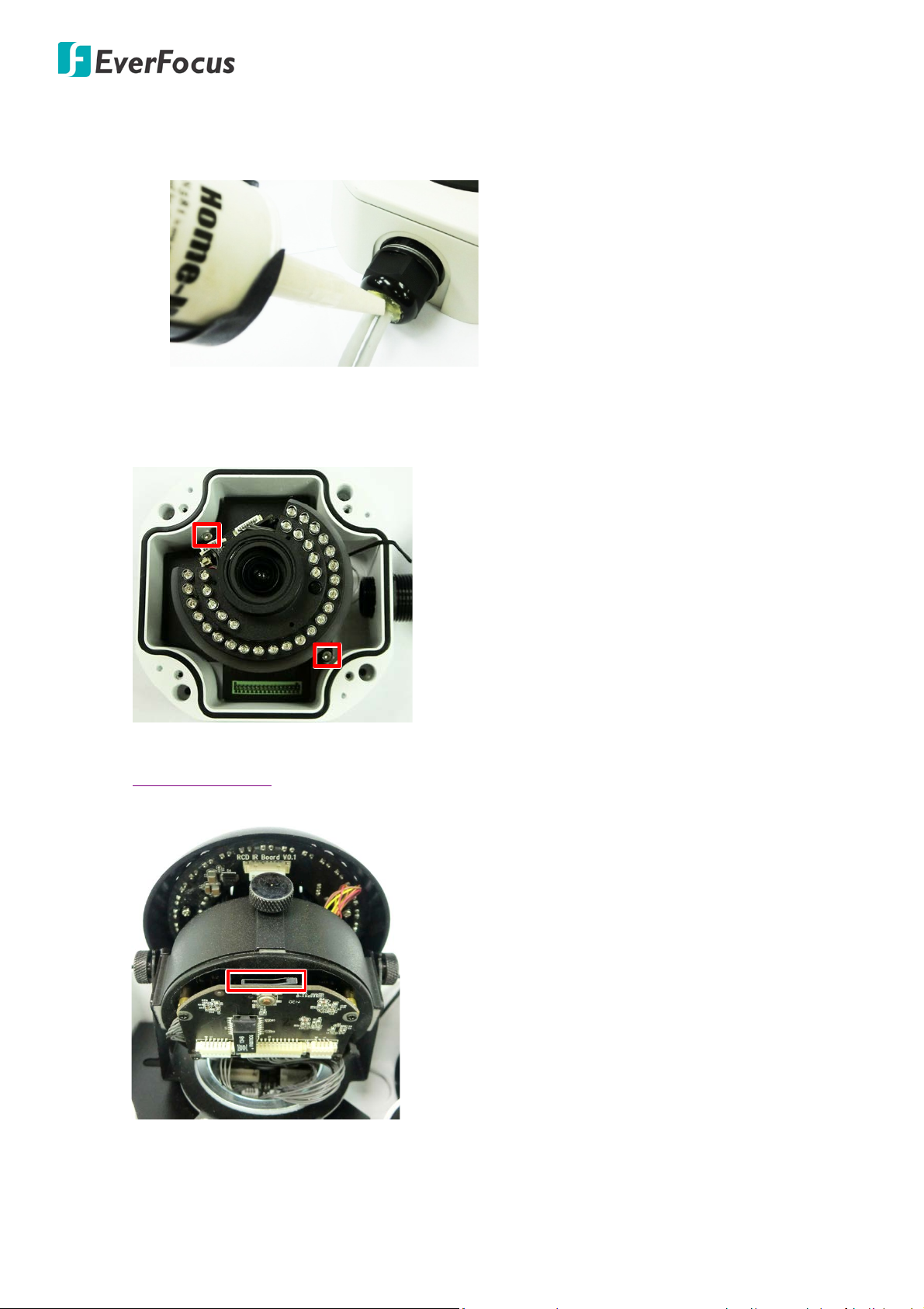
5. Connect the network / PoE cable to the LAN / PoE port on the camera module.
If you have difficulty connecting the network cable to the LAN / PoE port on the camera module,
you can unscrew these two screws and take out the camera module.
6. If you have inserted additional wires, connect the wires to the terminal block. Please refer to
4.3 Terminal Block for pin assignment.
7. Optionally insert a micro SD / SDHC card to the card slot.
11
EHN7221/7260/7360
360°
64°
180°
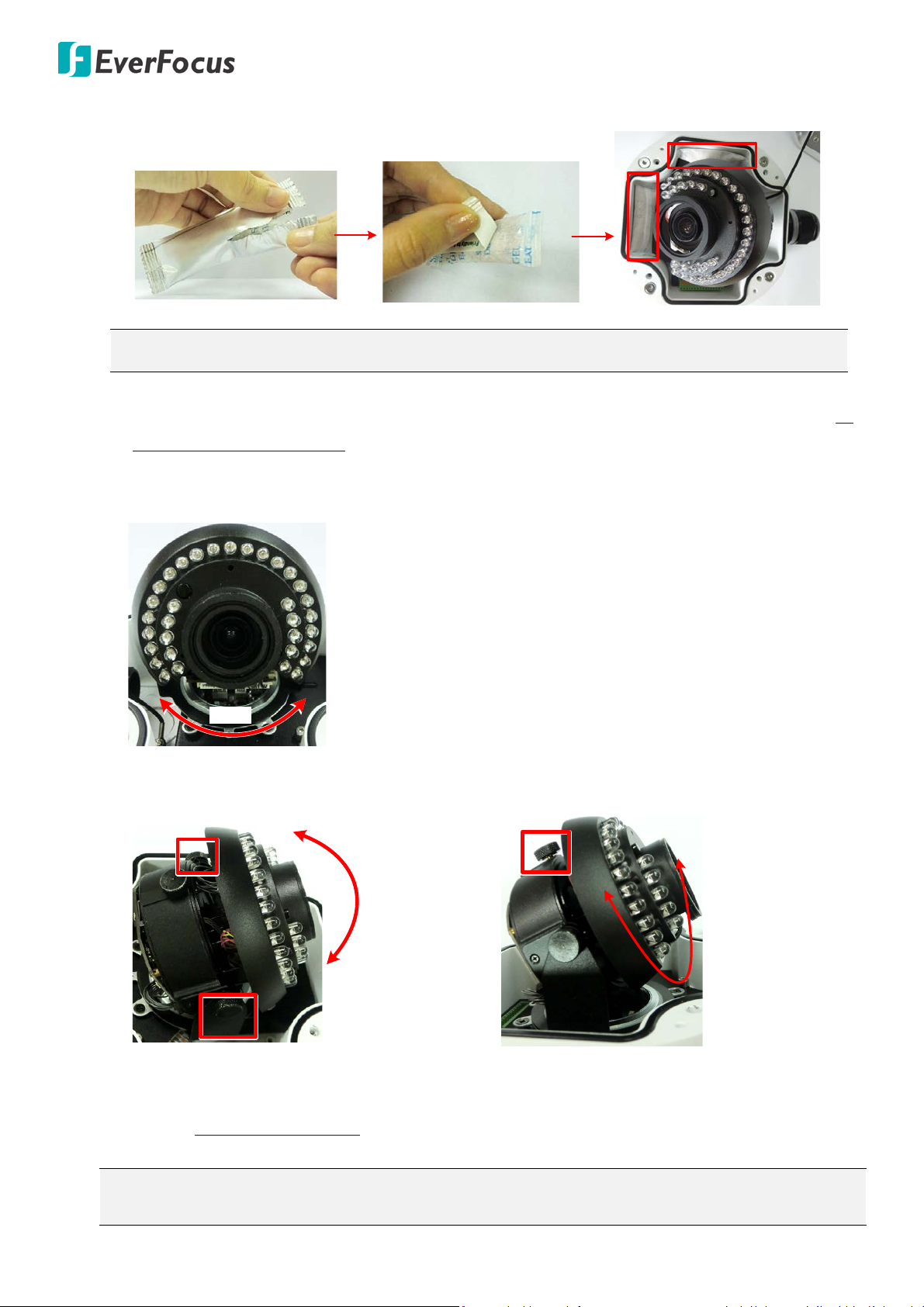
8. Stick the supplied 2 Desiccant Bags inside the camera case.
Note: It is recommended to replace the desiccant bags every time when you open the camera.
9. Access the camera live view for adjusting camera angles. To access the camera live view, see 5.
Accessing the User Interface.
To adjust the camera to a desired angle:
Pan Adjustment: Simply turn left / right for the top camera module.
Tilt Adjustment: Using the two tilt screws.
Rotational Adjustment: Using the rotate screw.
10. Screw the cover back to the camera case.
11. To adjust zoom and focus, please use Lens Control buttons on the Live View window. Please
refer to 5.4 Live View Window in the User’s Manual.
Note: Before start operating the IP camera, please make sure the camera date and time are
correct. To configure the camera date/time, go to System > Date/Time setting page on Web UI.
12
EHN7221/7260/7360
5. Accessing the User Interface
This section explains how to access the Web interface of the camera for configuration.
5.1. Checking the Dynamic IP Address
You can look up the IP address and access the Web interface of the IP camera using the IP Utility (IPU)
program, which is included in the software CD. The IP Utility can also be downloaded from EverFocus’
Website: http://www.everfocus.com.tw/HQ/Support/DownloadCenter_p1.aspx (Support > Download
Center > Keyword Search: IP Utility). Please connect the IP camera on the same LAN of your computer.
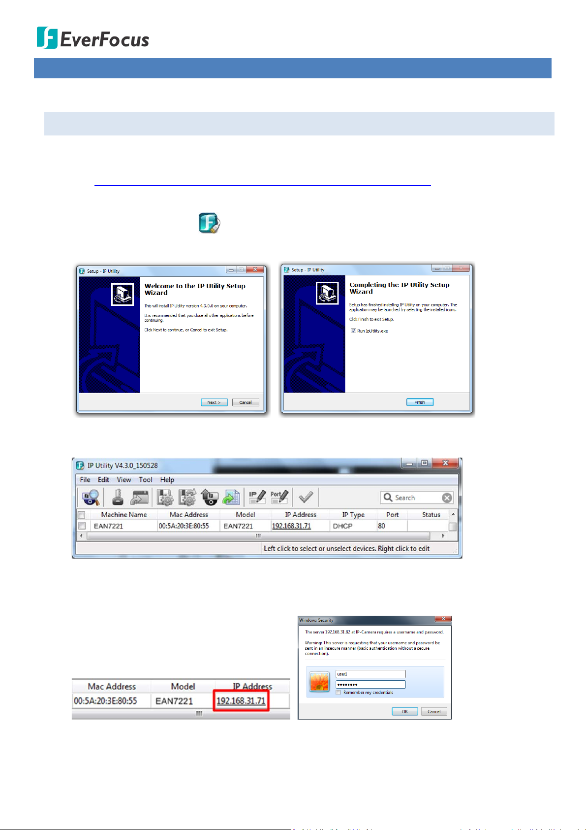
1. Save IP Utility Setup .exe in your computer. Double click the .exe file and follow the
on‐screen instructions to install the IP Utility.
2. Click the Finish button, the IP Utility will be automatically launched to search the IP devices
connected on the same LAN.
3. To access the Live View window, double click the IP address of the desired device, the login window
pops up. Type the user ID and password to log in. By default, the user ID is user1 and the password
is 11111111.
13
EHN7221/7260/7360
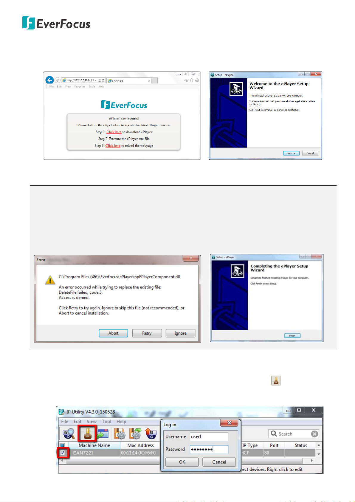
4. If you log in for the first time, follow the on‐screen instructions to update the latest Plugin version
(ePlayer). After reloading the webpage, the login window pops up again. Type the user ID and
password to log in again. By default, the user ID is user1 and the password is 11111111.
5. Now you will be able to see the remote live page.
Note:
1. The “Download ePlayer Instruction” page will only be prompted for the first time login in order to
update the system to the latest Plugin version.
2. If the Error window appears, please be sure to close ALL the Web browser windows first and then
click Retry. When the Completing the ePlayer Setup Wizard window shows up, click Finish. Then,
you can open a new browser again to access the camera’s remote Web interface.
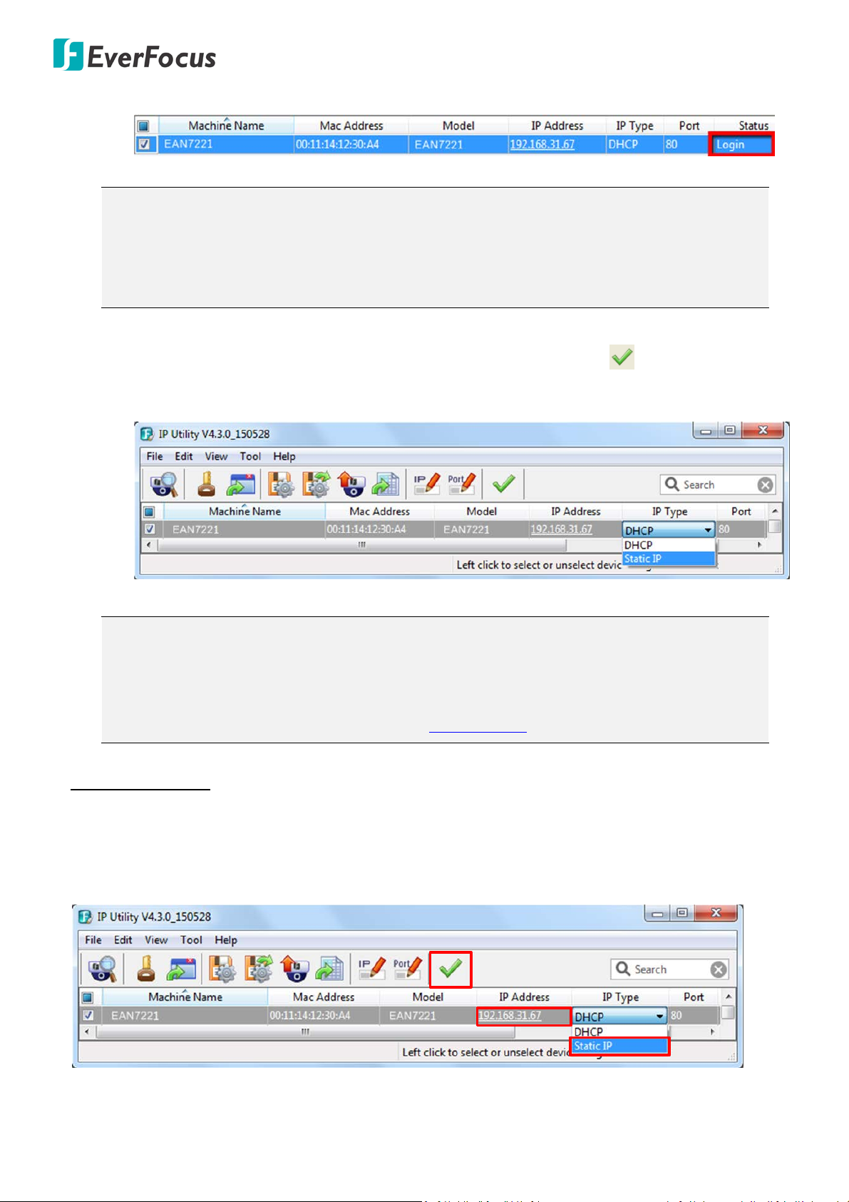
6. To optionally configure the Machine Name, IP Address, IP Type or Port Number using the IPU:
a. Log in the device by checking the desired model and then click the Log in icon. The Log in
dialog box appears.
14
EHN7221/7260/7360
1
2
3
b. Type the Username and Password and click OK. The Status column will display Login.
Note:
1. The default user ID is user1 and the default password is 11111111.
2. If you select more than one camera that has the same user ID / password, you will be able
to log in several cameras at once.
c. Right click the column to configure the setting. Click Apply Changes button to apply and
save the settings.
Note:
1. Most networks uses DHCP to assign IP address, if you are unsure of your network settings,
please consult your network administrators for configuration details.
2. If you want to set up PPPoE, please refer to 7.1.1 Network.
To set up a static IP:
By default, EverFocus’ IP cameras are set up with DHCP. To change the IP setting to static IP, select Static
IP from IP Type drop-down list and set up the desired IP Address, for example, 192.168.31.67.
Please also set up the Subnet Mask and Gateway. Click the Apply Changes button to apply and save the
settings.
15
EHN7221/7260/7360
1
2
3
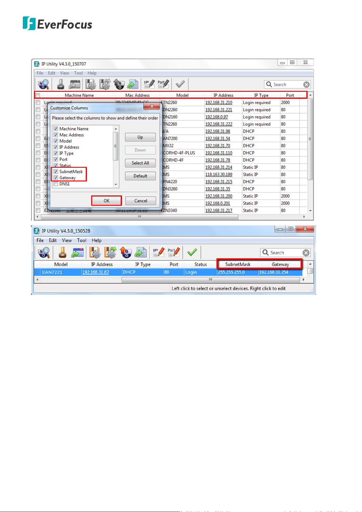
To show the Subnet Mask and Gateway items on the title bar, right click the title bar to display the
Customize Columns window, select Subnet Mask and Gateway and then click OK.
16
EHN7221/7260/7360
5.2. Settings for Microsoft Internet Explorer
If you have difficulties viewing live view or upgrading firmware, it is suggested to complete the following
settings of your computer.
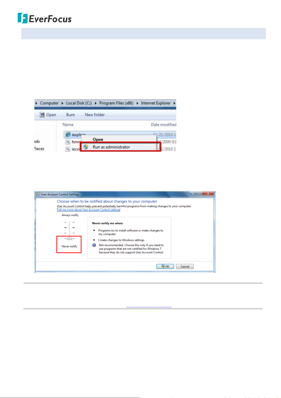
1. If your PC or laptop is running with Windows, it’ s required to run the browser as administrator
when first entering the remote web page of the device. Go to C:\Program Files (x86)\Internet
Explorer, right-click the browser and then click Run as administrator.
2. You may need to turn User Account Control off if you still can’t see the Remote Live View. On the
computer, click Start > Control Panel > System and Security > Action Center (click Change User
Account Control Settings), the User Account Control Settings window appears. Adjust the slide bar
to Never Notify and then click OK. Restart your computer if requested.
Note: For Windows 8 and Windows 10 user, if you still fail to view live view or upgrade firmware after
configuring Microsoft Internet Explorer setting, please refer to C. Snapshot / Record error message
(for Windows 8 and Windows 10 users). in 10. Troubleshooting for further configuration.
17
EHN7221/7260/7360
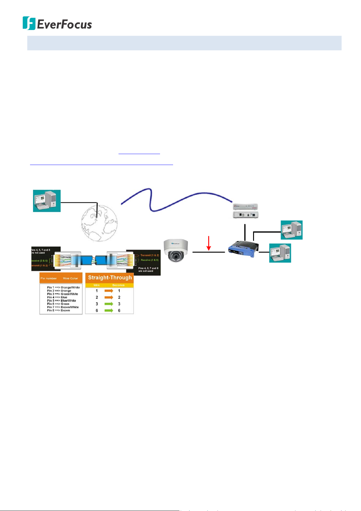
High-speed modem
Internet
Straight-through LAN patch cable
Router
Cat 5 Straight Through Cable
Left: Pinout of a straight-through cable.
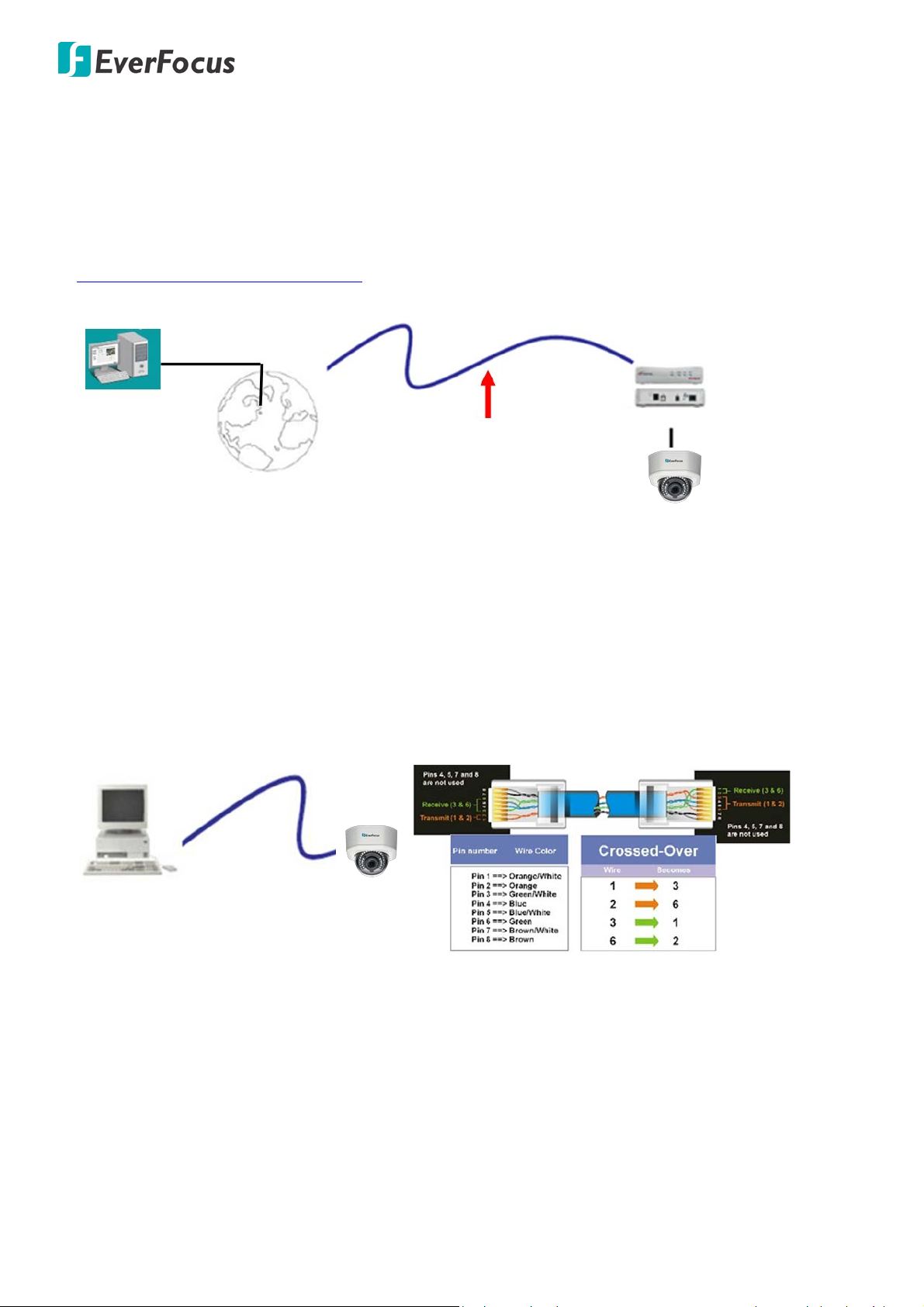
5.3. Connecting the Camera to the Network
There are three methods to connect the IP camera to the network: Router or LAN Connection, Direct
High-Speed Connection and One-to-One Connection.
Router or LAN connection
This is the most common connection in which the IP camera is connected to a router and allows multiple
users on and off site to see the IP camera on a LAN / WAN (Internet). The camera must be assigned an IP
address that is compatible with its LAN. By setting up port forwarding on the router, you can remotely
access the cameras from outside of the LAN via the Internet. To remotely access the Web interface of
the IP camera, please refer to 7.1.1 Network (DDNS Settings). To set up port forwarding, please refer to
Appendix D. Setting up Port Forwarding Function.
18
EHN7221/7260/7360
Cat 5
Straight Through Cable
High-speed modem
Internet
Cat 5
Right: Pinout of a crossed-over cable.
Direct High-Speed Connection
In a Direct High-Speed Connection, the camera connects directly to a modem without the need for a
router. You need to set the static or dynamic WAN IP address assigned by your ISP (Internet Service
Provider) in the camera’s configuration web pages. To access the camera, just type
“http://xxx.xxx.xxx.xxx”, where xxx.xxx.xxx.xxx is the IP address given by your ISP. If you have a dynamic
IP address, this connection may require that you use DDNS for a reliable connection. Please refer to
Appendix E. Setting up DDNS Function.
One-to-One Connection (Directly from PC to IP Camera)
You can connect directly without using a switch, router or modem. However, only the PC connected to
the camera will be able to view the IP camera. You will also have to manually assign a compatible IP
address to both the computer and the IP camera. Unless the PC has another network connection, the IP
camera will be the only network device visible to the PC. See the diagram below:
19
EHN7221/7260/7360
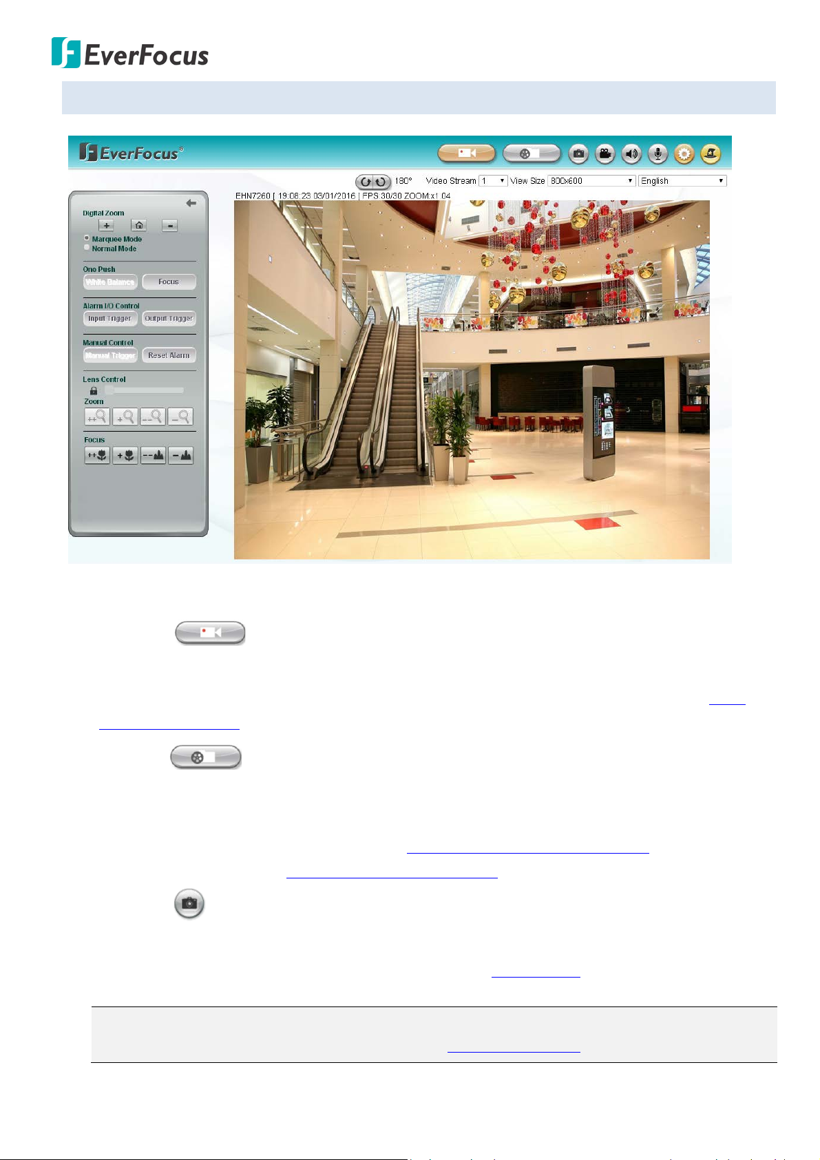
5.4. Live View Window
1. Live View
Click the Live View button to display the Live View window. If you experience video feed lag time (if
connected via Internet), you can reduce the resolution or limit the number of streams. See 7.2.1
Streaming and Audio.
2. Playback
Click the Playback button to play back the recorded data directly from the on-camera micro SD /
SDHC card. For this function to become active, you have to insert a micro SD / SDHC card into the
micro SD / SDHC card slot on the camera (see 6.2 Setting up the Playback Function). For the tested
card brands, please refer to Appendix A. Tested Card Brands.
3. Snapshot
Click the Snapshot button to take a snapshot. By default, the snapshot will be saved at
C:\EverFocus\. To change the location, see Record to PC in 7.1.3 Storage.
Note: For Microsoft IE10 and above users, some settings have to be complete to enable this
function (see B. Snapshot/Record error message in 10. Troubleshooting).
20

EHN7221/7260/7360
4. Record
Click the Record button to start / stop recording the current video stream. By default, this icon is
only for one-minute video recording and the recordings will be saved at C:\EverFocus\. To change
the recording time, see File Size in 7.1.3 Storage. To change the location, see Record to PC in 7.1.3
Storage. To record long-period recordings, please set up a recording schedule (see Schedule
Settings in 7.3.2. Event). To ch ange the source video stream, use the Video Stream drop-down list
on the Live View Window. To c h ange the recording format, see Recording and Snapshot Settings in
7.1.3 Storage.
Note: For Microsoft IE10 and above users, some settings have to be complete to enable this
function (see B. Snapshot/Record error message in 10. Troubleshooting).
5. Audio / Microphone
Click the Audio and Microphone buttons to switch the sound on / off for the speakers and
microphones respectively (if such external devices have been connected to the camera directly or
via the network). To activate the Audio function, the Enable Audio must be selected. See Audio
Settings in 7.2.1 Streaming and Audio. Note that the camera provides the TRS line-in / out terminal
I/O, therefore, TRS microphones / speakers with a (built-in) amplifier and external power supply are
required.
6. Setting
Click the Setting button to enter the Settings page (see 7. Settings).
7. Wizard
Click the Wizard button to enter the Setup Wizard.
21
EHN7221/7260/7360
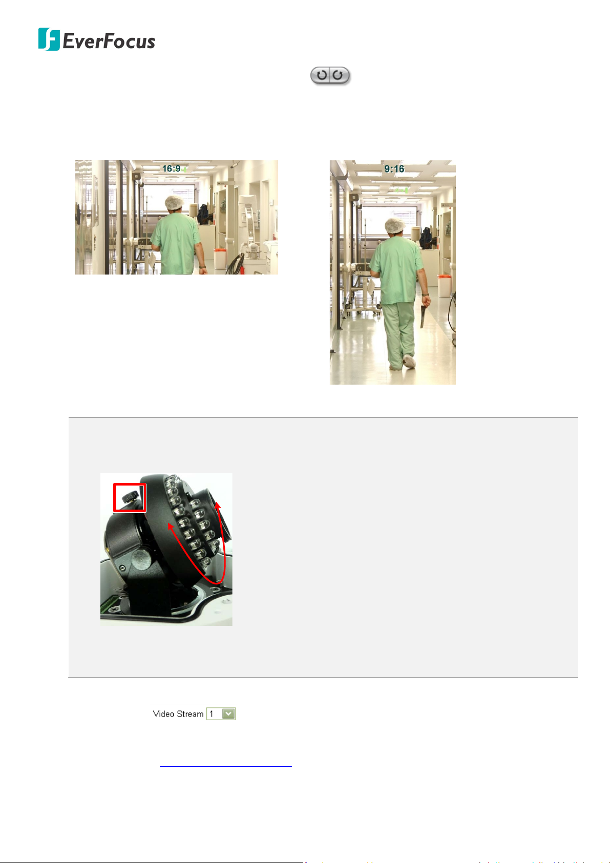
90°
8. Hallway Display (9:16): Click the Rotate button to rotate the live image. The rotation
degree will display next to the button. This function allows users to monitor vertically-oriented
areas such as hallway, corridors and aisles. Note that once you rotate the live image, the recordings
and snapshots will also be rotated.
Note: To achieve the best 9:16 display effect, it’s recommended to:
a. Install the camera sideways by rotating the camera to the left or right by 90°.
b. Select a 16:9 View Size (e.g. 1920 x 1080 / 1024 x 768).
c. Use the Rotate button.
9. Video Stream
Select the Video Stream (Stream 1 and Stream 2) that will be displayed in the live view window on
the bottom. (see 7.2.1 Streaming and Audio). The default setting is Stream 1 only. If extra streams
required, EverFocus can customize the settings.
22
EHN7221/7260/7360
Select this mode to set the zoom level in the magnified
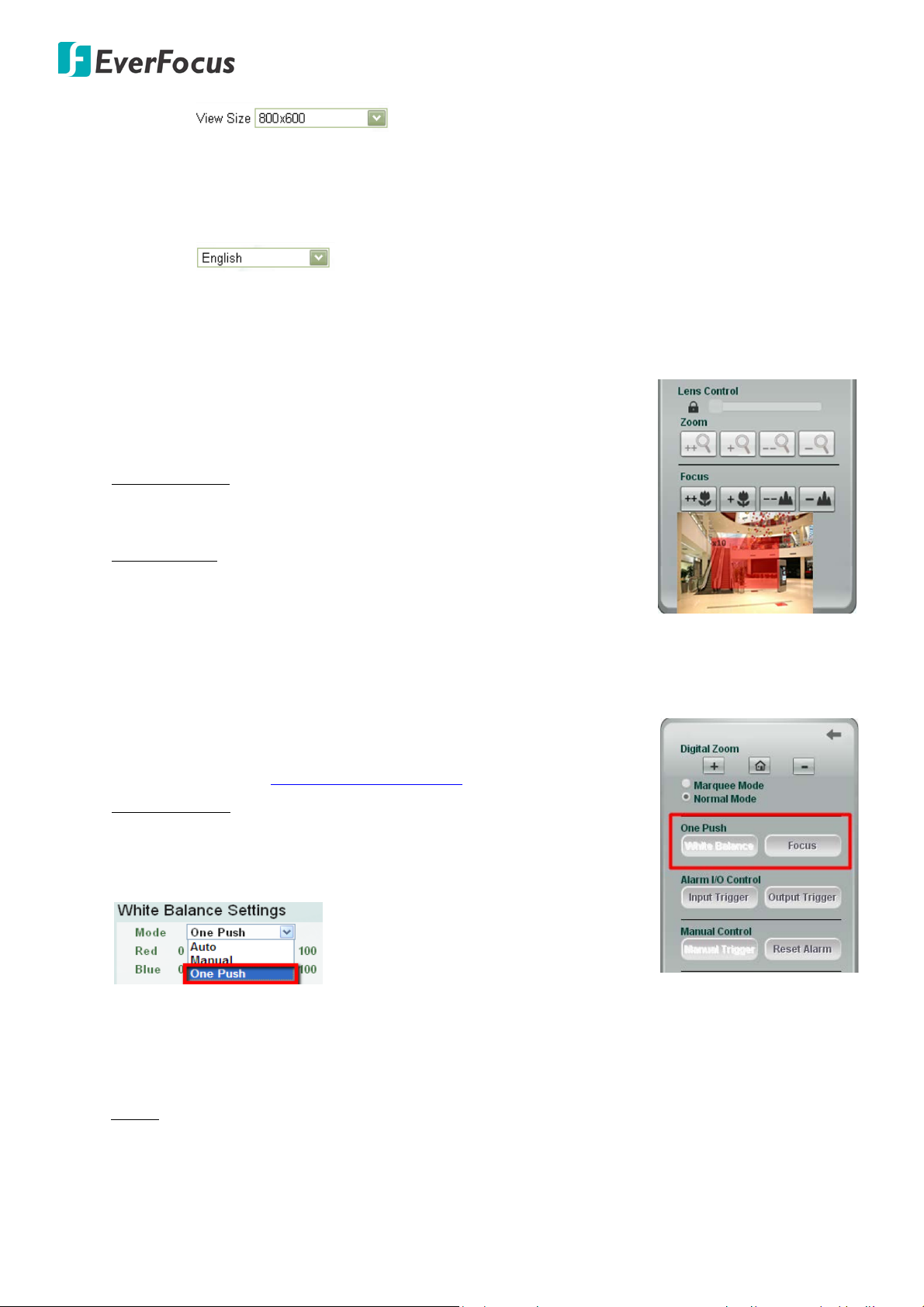
10. View Size
Use this to select the appropriate view size and shape of the live view window on the bottom. A
smaller size might increase transmission speed and video quality.
11. Language
Click the Language drop-down list to select the desired language.
12. Digital Zoom
Click the zoom in / zoom out buttons to zoom in / out the camera live
view. Click the Home button to go back to the home position.
Marquee Mode: Select this mode to drag around a portion of the live
view window you want to zoom into with your mouse.
Normal Mode:
window. You can roll the mouse wheel to zoom in / out the camera
live view. Clicking on the magnified image will re-center the image
around that point.
13. One Push
The One Push buttons can be displayed on the live view window by
enabling the Show One Push Buttons function in the Live View
Layout Settings (see 7.1.4 Display and Overlay).
White Balance: To enable the button (turned from faded to clear), on
the Setting > Advanced > Camera Settings > Image, select One Push
from the mode drop-down list in the White Balance Settings field and
click the Apply button.
Once this is done, clicking the White Balance button on the Live View Window will instruct the
camera to adjust the white balance settings, and these settings will be active until the button is
clicked again. This is like a “semi-automatic” way to adjust white balance to suit the user, if the Auto
or Manual mode does not give the result the user wants.
Focus: The Focus (Auto Focus) button is enabled by default on the Live View window. Click the Focus
button to instruct the camera to focus automatically. To hide the Focus button on the Live View
window, disable the Show One Push Buttons function in the Live View Layout Settings (see 7.1.4
Display and Overlay).
23
EHN7221/7260/7360
14. Alarm I/O Control
Click the Input Trigger or Output Trigger buttons to trigger the alarm input / alarm output directly
from the window. If you have configured an event (in the Event List) that will trigger a reaction (like
a recording) when an “Alarm Input” event occurs, clicking the Input Trigger button will trigger that
reaction. If you have connected the camera alarm output to an external device, click the Output
Trigger button will trigger that device.
15. Manual Control
The Manual Trigger button can be displayed on the live view window by setting up a Manual Trigger
Event in the Event Management (see 7.3.2 Event).
Click the Manual Trigger button to trigger an event directly from the window. If you have configured
an event (in the Event List) that will trigger a reaction (like a recording) when a “Manual Trigger”
event occurs, clicking this button will trigger that reaction. You can select what that reaction will be.
You can, for instance, set the camera to record the audio / video feed to the micro SD card on board
the camera. You can then click on the Playback button to open the Playback page and search for
and play all such recordings that had been stored on the card. Such event actions will be effective
once they have been configured in the Event List (see 7.3.2 Event). Click the Reset Alarm button to
reset the alarm output remotely.
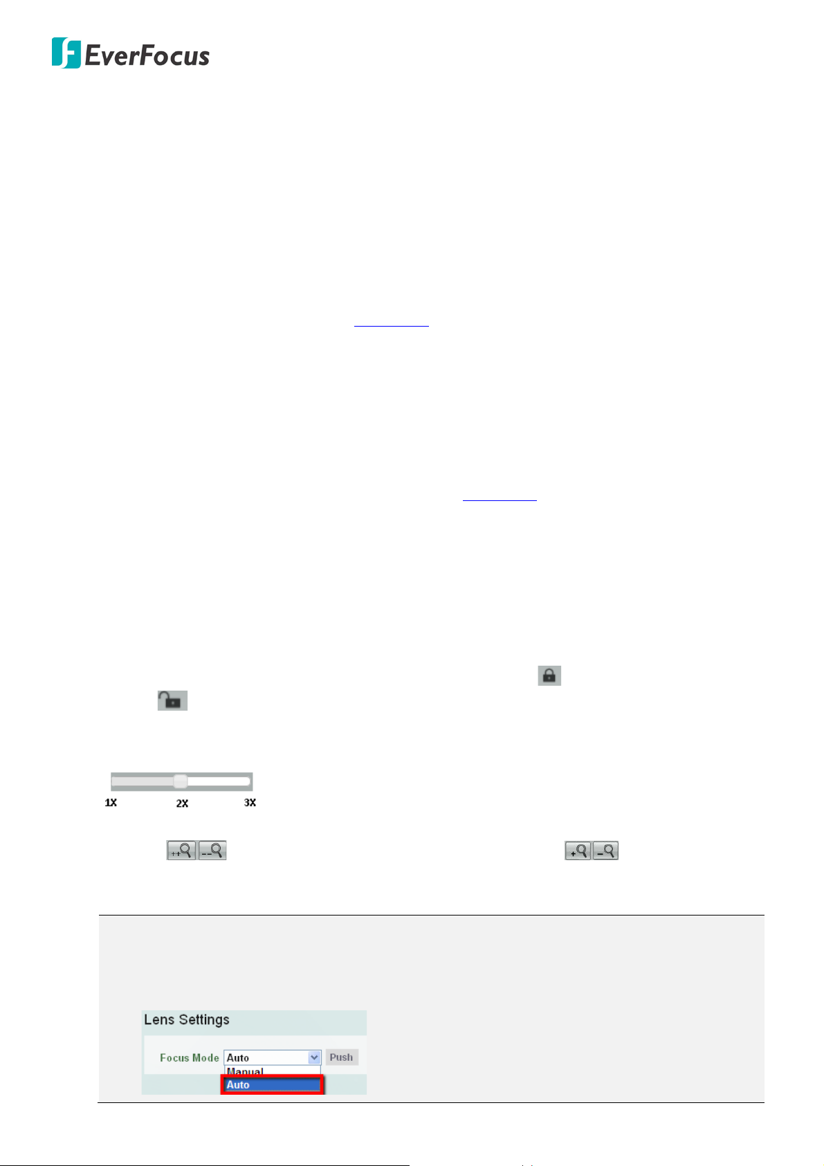
16. Lens Control
The Lens Control buttons can be hidden on the Live View window by disable the Show Lens Control
Buttons function in the Live View Layout Settings (see 7.1.4 Display and Overlay).
Zoom (Optical Zoom)
To adjust zoom buttons and slide bar, you need to click the Lock icon to unlock first. Click the
Unlock icon again to lock the zoom functions. The slide bar can be used for major adjustment
while zoom buttons are suitable for fine tuning. The bar value is defined by 1X, 2X and 3X values as
shown below. Slide the bar to the desired value.
When using buttons to control the zoom in / out actions, the slide bar will act accordingly. Click and
hold the buttons to continuously zoom in / out. Click the buttons to zoom in /
out one step forward or backward.
Note:
1. If you select Auto from the Focus Mode drop-down list, the camera will automatically
adjust focus every time you click the Zoom in / out buttons.
24
 Loading...