

EverFocus PARAGON FHD 16x4 User Manual
PARAGON FHD 16x4
16CH, H.264, 1080p Full HD DVR
User’s Manual
The content in this manual is subject to change without notice.
Copyright © EverFocus Electronics Corp.
Release Date: May, 2016

EVERFOCUS ELECTRONICS CORPORATION
PARAGON FHD 16x4
User’s Manual
1995-2016 EverFocus Electronics Corp.
www.everfocus.com.tw
All rights reserved. No part of the contents of this manual may be reproduced or transmitted in any form
or by any means without written permission of the Everfocus Electronics Corporation.
QuickTime is a registered trademark of the Apple Computer, Inc.
Windows is a registered trademark of the Microsoft Corporation.
Linksys is a registered trademark of the Linksys Corporation.
D-Link is a registered trademark of the D-Link Corporation.
DynDNS is a registered trademark of the DynDNS.org Corporation.
Other product and company names mentioned herein may be the trademarks of their respective owners.

Safety Precautions
Refer all work related to the installation of this product to qualified service personnel or
system installers.
Do not block the ventilation openings or slots on the cover.
Do not drop metallic parts through slots. This could permanently damage the appliance.
Turn the power off immediately and contact qualified service personnel for service.
Do not attempt to disassemble the appliance. To prevent electric shock, do not remove
screws or covers. There are no user-serviceable parts inside. Contact qualified service
personnel for maintenance. Handle the appliance with care. Do not strike or shake, as this
may damage the appliance.
Do not expose the appliance to water or moisture, nor try to operate it in wet areas. Do
take immediate action if the appliance becomes wet. Turn the power off and refer servicing
to qualified service personnel. Moisture may damage the appliance and also may cause
electric shock.
Do not use strong or abrasive detergents when cleaning the appliance body. Use a dry cloth
to clean the appliance when it is dirty. When the dirt is hard to remove, use a mild
detergent and wipe gently.
Do not overload outlets and extension cords as this may result in a risk of fire or electric
shock.
Do not operate the appliance beyond its specified temperature, humidity or power source
ratings. Do not use the appliance in an extreme environment where high temperature or
high humidity exists. Use the DVR at temperatures within 0°C~40°C / 32°F~104°F (Storage).
The input power source is 100-240 VAC~.
Read Instructions
All the safety and operating instructions should be read before the unit is operated.
Retain Instructions
The safety and operating instructions should be retained for future reference.
Heed Warnings
All warnings on the unit and in the operating instructions should be adhered to.
Follow Instructions
All operating and use instructions should be followed.
ii

Cleaning
Unplug the unit from the outlet before cleaning. Do not use liquid cleaners, abrasive or
aerosol cleaners. Use a damp cloth for cleaning
Attachments
Do not use attachments not recommended by the product manufacturer as they may
cause hazards.
Water and Moisture
Do not use this unit near water-for example, near a bath tub, wash bowl, kitchen sink, or
laundry tub, in a wet basement, near a swimming pool, in an unprotected outdoor
installation, or any area which is classified as a wet location.
Servicing
Do not attempt to service this unit by yourself as opening or removing covers may expose
you to dangerous voltage or other hazards. Refer all servicing to qualified service
personnel.
Power Cord Protection
Power supply cords should be routed so that they are not likely to be walked on or pinched
by items placed upon or against them, playing particular attention to cords and plugs,
convenience receptacles, and the point where they exit from the appliance.
Object and Liquid Entry
Never push objects of any kind into this unit through openings as they may touch
dangerous voltage points or short-out parts that could result in a fire or electric shock.
Never spill liquid of any kind on the unit.
Battery
Risk of explosion if battery is replaced by an incorrect type. Dispose of used batteries
according to the instructions.
a. Use only two AAA dry cell batteries.
b. Do not dispose of the batteries in a fire as it may explode.
RTC (Real Time Clock) Battery
When encounter failure of time calibration of your DVR, the issue may be caused by
running-out of RTC battery. Users will have to change the RTC battery on the main board
of the DVR.
iii
Federal Communication Commission Interference Statement
ATTENTION! This is a class A product which may cause radio interference in a
domestic environment; in this case, the user may be urged to take adequate measures.
This equipment has been tested and found to comply with the limits for a Class B digital
device, pursuant to Part 15 of the FCC Rules. These limits are designed to provide
reasonable protection against harmful interference in a residential installation. This
equipment generates, uses and can radiate radio frequency energy and, if not installed
and used in accordance with the instructions, may cause harmful interference to radio
communications. However, there is no guarantee that interference will not occur in a
particular installation. If this equipment does cause harmful interference to radio or
television reception, which can be determined by turning the equipment off and on, the
user is encouraged to try to correct the interference by one of the following measures:
•Reorient or relocate the receiving antenna.
•Increase the separation between the equipment and receiver.
•Connect the equipment into an outlet on a circuit different from that to which the
receiver is connected.
•Consult the dealer or an experienced radio/TV technician for help.
FCC Caution: Any changes or modifications not expressly approved by the party
responsible for compliance could void the users’ authority to operate this equipment.
This Product is RoHS compliant.
WEEE
Your EverFocus product is designed and manufactured with high quality materials and
components which can be recycled and reused. This symbol means that electrical and
electronic equipment, at their end-of-life, should be disposed of separately from your
household waste. Please, dispose of this equipment at your local community waste
collection/recycling centre. In the European Union there are separate collection systems
for used electrical and electronic product.
Please, help us to conserve the environment we live in!
This product complies with the High-Definition Multimedia Interface (HDMI)
Specification Adopter Agreement.
The information in this manual was current upon publication. The manufacturer reserves the right
to revise and improve his products. Therefore, all specifications are subject to change without prior
notice. Manufacturer is not responsible for misprints or typographical errors.
Please read this manual carefully before installing and using this unit. Be sure to keep it handy for
later reference.
iv

TABLE OF CONTENTS
1. Introduction ................................................................................................................... 1
1.1 Features ............................................................................................................................. 3
1.2 eZ. Controller Function Description .................................................................................. 4
1.3 Packing List ........................................................................................................................ 6
1.4 Optional Accessories ......................................................................................................... 7
1.5 Dimensions ........................................................................................................................ 7
1.6 Front Panel......................................................................................................................... 8
1.7 Rear Panel ........................................................................................................................ 10
2. Installation................................................................................................................... 12
2.1 Hard Disk Installation ....................................................................................................... 12
2.1.1 Hard Disk Compatibility List ............................................................................... 15
2.2 Rack Mount ...................................................................................................................... 15
2.3 Basic Connection ............................................................................................................. 16
2.3.1 Monitor Connection ........................................................................................... 17
2.3.2 Alarm I / O .......................................................................................................... 18
2.3.3 RS-485 Port ......................................................................................................... 19
2.4 Turning On / Off the Power ............................................................................................. 19
2.5 Checking the Dynamic IP Address ................................................................................... 20
2.6 Connecting the DVR to the Network ............................................................................... 25
2.6.1 Router or LAN Connection ................................................................................. 25
2.6.2 Direct High-Speed Connection ........................................................................... 28
2.6.3 One-to-One Connection ..................................................................................... 29
3. Mouse and Front Panel Button Operation .................................................................... 33
3.1 USB Mouse Operation ..................................................................................................... 33
3.1.1 How to Select a Channel / Enable Audio............................................................ 33
3.1.2 OSD Root Menu .................................................................................................. 33
3.1.3 Field Input Options ............................................................................................. 34
3.2 Front Panel Buttons Operation ....................................................................................... 35
3.2.1 Front Panel Review ............................................................................................ 35
3.2.2 How to Select a Channel / Enable Audio............................................................ 35
3.2.3 OSD Root Menu .................................................................................................. 35
3.2.4 Field Input Options ............................................................................................. 36
3.3 General Operation ........................................................................................................... 37
3.3.1 Login ................................................................................................................... 37
3.3.2 Forget Your Password ........................................................................................ 38
3.3.3 Camera Selection ............................................................................................... 38
3.3.4 Audio Selection .................................................................................................. 38
4. OSD Root Menu ........................................................................................................... 40
4.1 PTZ ................................................................................................................................... 42
4.1.1 Express Control of PTZ ....................................................................................... 44
4.2 Layout Switching .............................................................................................................. 45
v

4.3 Channel Switching ........................................................................................................... 45
4.4 Display.............................................................................................................................. 46
4.5 Sequence ......................................................................................................................... 47
4.6 Zoom ................................................................................................................................ 47
4.7 Archiving the Recordings or Log Data to the USB or DVD ............................................... 49
4.8 Logout .............................................................................................................................. 53
4.8.1 Temporarily Logout ............................................................................................ 54
5. Search and Playback..................................................................................................... 56
5.1 Quick Playback ................................................................................................................. 56
5.2 Playback Bar ..................................................................................................................... 57
5.3 Searching the Recordings for Playing Back ...................................................................... 59
5.3.1 Time Search ........................................................................................................ 59
5.3.2 Event Search ....................................................................................................... 60
5.3.3 Smart Search ...................................................................................................... 61
5.3.4 Snapshot Search ................................................................................................. 63
5.3.5 POS Search ......................................................................................................... 65
6. System ......................................................................................................................... 67
6.1 Express ............................................................................................................................. 69
6.2 Camera ............................................................................................................................. 70
6.2.1 Basic Setting ....................................................................................................... 70
6.2.1.1 Display Aspect Ratio ............................................................................. 72
6.2.2 Adjust Setting ..................................................................................................... 73
6.2.3 eZ Hopper ........................................................................................................... 74
6.3 Record .............................................................................................................................. 77
6.4 Event ................................................................................................................................ 78
6.4.1 Alarm .................................................................................................................. 78
6.4.1.1 Connect a Radio Clock to the DVR ........................................................ 80
6.4.2 Video Loss ........................................................................................................... 81
6.4.3 Motion ................................................................................................................ 83
6.4.4 Other .................................................................................................................. 86
6.5 Hard Disk .......................................................................................................................... 92
6.5.1 Disk ..................................................................................................................... 92
6.5.2 Lock/Format ....................................................................................................... 93
6.6 Display Setting ................................................................................................................. 94
6.6.1 Monitor OSD ....................................................................................................... 94
6.6.2 M/T SEQ ............................................................................................................. 95
6.7 Network Settings ............................................................................................................. 96
6.7.1 LAN ..................................................................................................................... 96
6.7.2 Email ................................................................................................................... 99
6.7.3 DDNS ................................................................................................................ 100
6.7.4 FTP .................................................................................................................... 106
6.7.5 Alarm Server ..................................................................................................... 107
6.7.6 Remote / Mobile .............................................................................................. 108
6.7.7 Network Test .................................................................................................... 109
6.8 Schedule Setting ............................................................................................................ 110
vi

6.8.1 Express Setup ................................................................................................... 110
6.8.2 Holidays ............................................................................................................ 111
6.8.3 Schedule ........................................................................................................... 112
6.9 System Setting ............................................................................................................... 115
6.9.1 Date / Time ....................................................................................................... 115
6.9.2 Daylight Saving ................................................................................................. 117
6.9.3 User Group ....................................................................................................... 118
6.9.4 User Management............................................................................................ 120
6.9.5 I/O Control ........................................................................................................ 123
6.9.6 EKB200 Setting ................................................................................................. 124
6.9.7 Miscellaneous ................................................................................................... 126
6.10 Information ................................................................................................................. 128
6.10.1 System ............................................................................................................ 128
6.10.2 Log .................................................................................................................. 129
7. Remote Access to the DVR ......................................................................................... 130
7.1 Accessing the DVR on the Network ............................................................................... 130
7.2 Remote Live View .......................................................................................................... 134
7.3 Menu Bar ....................................................................................................................... 136
7.4 Remote Playback ........................................................................................................... 137
8. Specifications ............................................................................................................. 138
9. Troubleshooting ......................................................................................................... 141
Appendix A: Network Overview ......................................................................................... 142
Appendix B: Linksys & D-Link Port Forwarding ................................................................... 146
Appendix C: Timing of Alarm Modes .................................................................................. 150
Appendix D: Express Setup Recording Value Selection Rules .............................................. 153
Appendix E: IR Remote Control .......................................................................................... 155
Appendix F: RTSP URL Syntax............................................................................................. 156
Appendix G: Auto HDD Retry Mechanism .......................................................................... 159
vii

PARAGON FHD 16x4
1
Chapter
1. Introduction
EverFocus PARAGON FHD 16x4 is our new eZ.HD series DVR, which adopts the latest Analog HD
technology, permitting it to deliver excellent 1080p full HD quality images that are far superior to
traditional analog CCTV. The eZ.HD series is easy to install and can integrate with the existing CCTV
systems without re-cabling, so this new eZ.HD 1080p full HD video surveillance system will
definitely be your best cost-effective solution.
The PARAGON FHD 16x4 DVR supports 16-channel analog video inputs with resolution ranging
from D1, 960H, 720p to 1080p full HD and also features triple streams for live view, playback and
recording. It can record and play back up to 480 (NTSC) / 400 (PAL) frames per second at all
resolutions. In addition, this new series DVR supports both standard coaxial and UTP (Unshielded
Twisted Pair) cable, allowing for long-distance transmission of full HD images with zero video
latency.
This model is designed with a high-performance hardware which has 3 video outputs (HDMI, VGA
and BNC) for local monitoring, 16 video looping outputs, audio in/out, alarm in/out, RS-485 serial
interface, 3 USB interfaces and 1 RJ45 (10/100/1000) Ethernet interface. Other than that, the
PARAGON FHD 16x4 can be expanded up to 5 SATA devices (4 SATA HDDs and 1 eSATA), ensuring
large capacity of the eZ.HD full HD video recordings. Users can also easily operate the machine
using a USB mouse or via the front panel buttons and jog-dial/shuttle wheel.
EverFocus also provides mobile apps for users to view the eZ.HD 1080p full HD camera streams via
their mobile devices (iOS or Android platforms) and also supports web UI for users to remotely
access the surveillance system. Moreover, it is integrated with our powerful CMS platform, Genie
XMS, so it can be applied in more surveillance scenarios and easily scaled up in the future.
1
PARAGON FHD 16x4
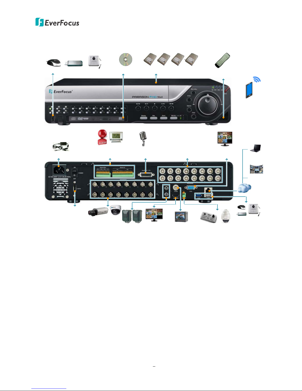
Mouse
Internal 3.5" HDDs (Optional)
DVD Burner
Main Monitor
(HDMI)
Line Level
Audio Out
Line Level
Audio In 1~16
*Call Monitor
(CVBS)
Alarm In / Out
or Radio Clock
Web Remote
Client
CMS:
Genie XMS
EKB500 Keyboard
/ PTZ Camera
Power Supply
Mobile App:
MobileFocus
MobileFocusHD
eZ.HD Camera
1~16
Video Looping
Output 1~16
eSATA HDD Expansion
Mouse / USB /
EKB200
IR Remote
Control
/ USB / EKB200 Keyboard
Network
*Call Monitor
(VGA)
* The 2 Call monitors can work simultaneously and share the identical functionality. To configure
the monitor settings, please refer to 6.6 Display Setting.
2

PARAGON FHD 16x4
1.1 Features
• Megapixel resolution over standard coaxial / UTP (Unshielded Twisted Pair) cable
• eZ upgrade to Full HD resolution
• 1080p full HD, 720p, 960H or D1 simultaneous video inputs
• H.264 compression format for enhancing recording capacity and improving network image
transmission speed
• eZ Controller function: Control camera OSD settings and PTZ operation directly from DVR
end (please refer to 1.2 eZ.Controller Function Description for more details)
• Multiple Monitors: Separately configure main and call monitor outputs
• High bandwidth full HD recording with recordable reduced bandwidth stream for mobile or
multiplexed viewing applications.
• Supports live monitoring and playback of video from mobile devices via MobileFocus (Plus) /
MobileFocusHD (Plus) Apps.
• Multiple Control Inputs: mouse / front panel / IR remote controller
• Remote configuration supports from built-in web interface
• Ethernet interface for remote network viewing and control
• eZ Hopper function: Only one mouse to control up to 16 connected EverFocus DVRs / NVRs
• Supports radio-controlled clock for time synchronization
• Integration with Genie XMS CMS
• Multi-language support
3
PARAGON FHD 16x4
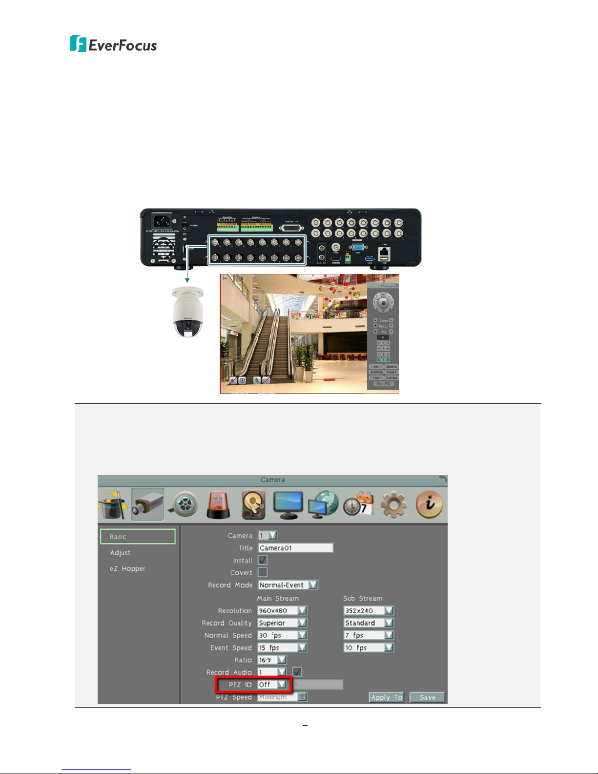
PTZ Cameras
Tip: You can also bring
up the camera OSD
through Preset 95.
1.2 eZ. Controller Function Description
eZ.Controller: Easily control PTZ camera from DVR using only coaxial cable.
eZ.Controller allows users to control PTZ camera from DVR using only a coaxial cable without the
need of a RS-485 cable between the PTZ camera and the DVR. Users can easily operate Zoom,
Focus, Iris, Direction, Auto Pan, Preset, Tour and Pattern functions to the PTZ camera through
DVR.
Note:
1. The eZ.Controller function for PTZ control is only supported for EverFocus AHD (1080p,
720p) PTZ cameras.
2. After connecting the PTZ camera to the DVR through the coaxial cable, you will have to go
to the OSD Menu to turn the PTZ ID function off (System < Camera < Basic).
4
PARAGON FHD 16x4
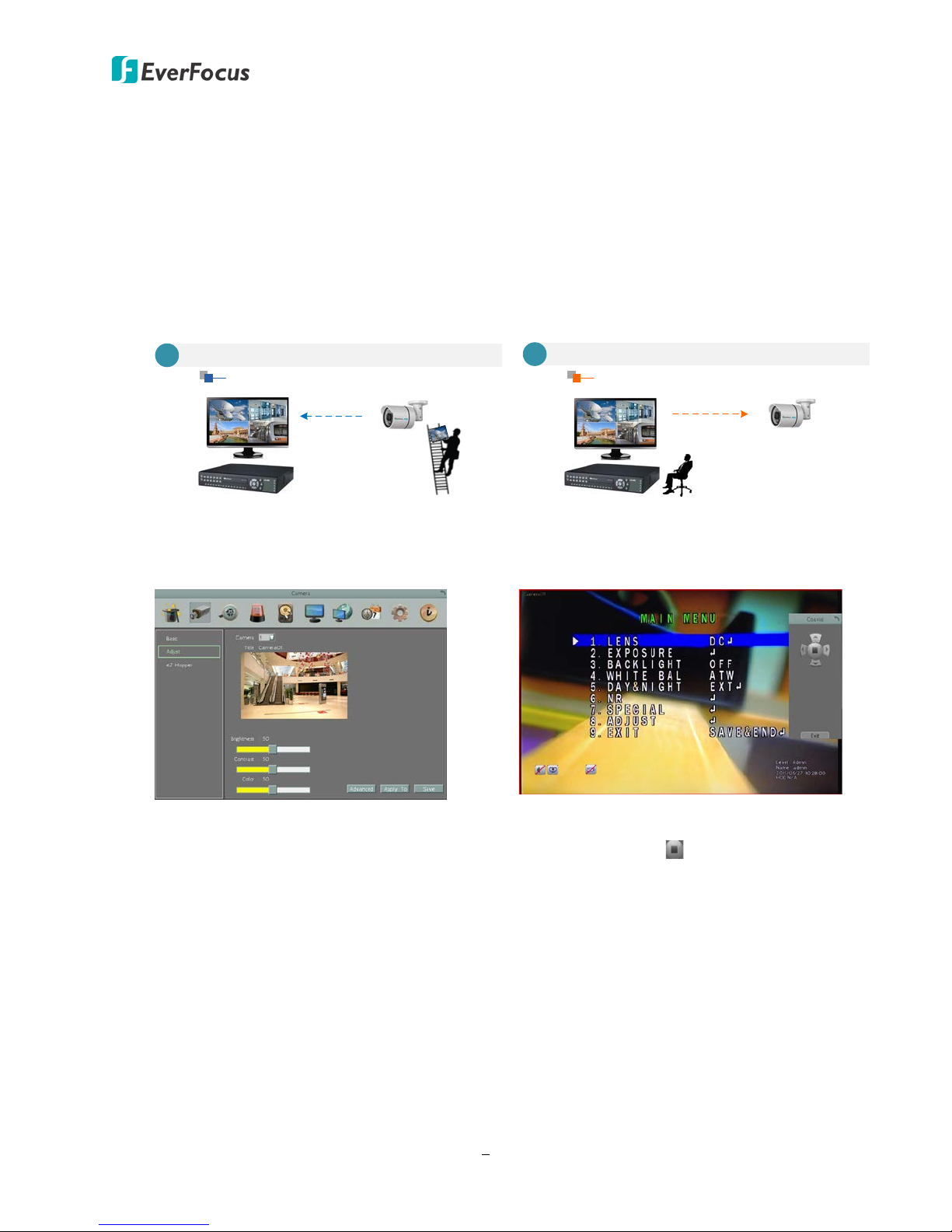
Traditional Way to Control Camera OSD
Control Camera OSD at Camera End
A
Camera EndDVR End
Use eZ.Controller to Control Camera OSD
Camera OSD Control Directly at DVR End
DVR End
Camera End
B
eZ.Controller: Easily control eZ.HD camera’s OSD at the DVR end.
Traditionally, the CCTV installer needs to take a portable monitor to connect to the camera
for controlling the camera OSD at the camera installation site as the Diagram A below. It will
take extra effort, time and people to adjust the camera.
Now, EverFocus’ eZ.Controller allows users to control the camera OSD simply on the monitor
at the DVR end as illustrated in Diagram B.
How to Control eZ.HD Camera’s OSD at the DVR End?
1. On the DVR’s OSD setting menu, go
to Configuration > Camera > Adjust.
Select a camera you want to adjust.
2. Click the Advanced button, and the
camera live view with the Coaxial
Panel will be displayed.
3. To display the OSD menu, click the
4. You can use the direction buttons on
5. To exit the camera OSD setting, click
Enter button on the Coaxial Panel.
the Coaxial Panel to control the
camera’s OSD setting menu.
Exit to return to the Adjust setting
page.
5
PARAGON FHD 16x4
•
•
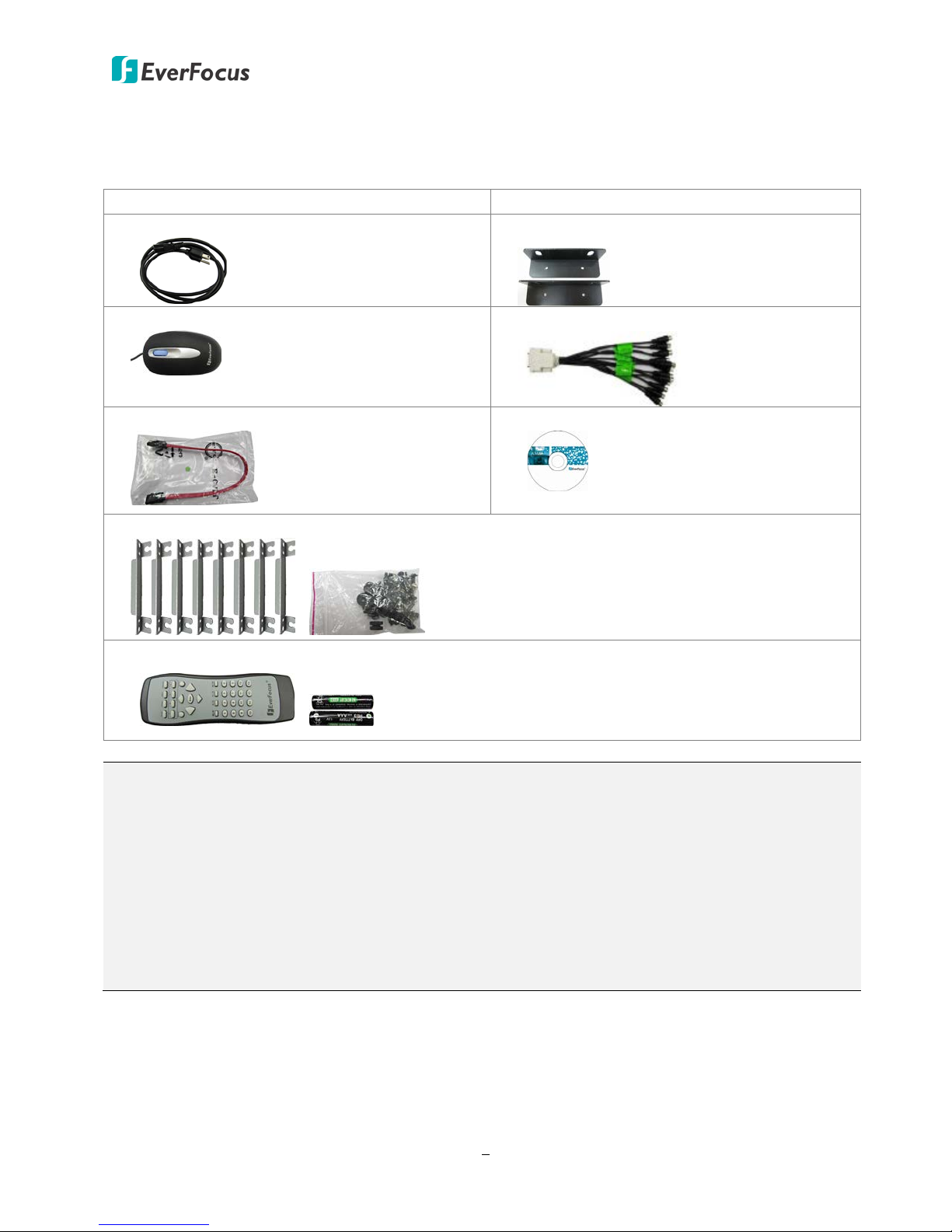
1.3 Packing List
DVR x 1
• Power Cord x 1
• Mouse x 1
Quick Installation Guide x 1
• Rack Ear x 2
• Audio Cable x 1
• SATA Cable x 4 (for internal HDD connection)
• CD x 1 (Please see Note 3.)
• Internal HDD Bracket x 8 (with 16 Rubber Spacers, 16 Black Long Screws and 16 Silver Screws)
( )
• IR Remote Control x 1 (with two AAA batteries) *Please see Note 4.
( )
Note:
1. Equipment configurations and supplied accessories vary by country. Please consult your local
EverFocus office or agents for more information. Please also keep the shipping carton for
possible future use.
2. Contact the shipper if any items appear to have been damaged in the shipping process.
3. The CD contains the IP Utility software, EFPlayer, User Manual and Quick Installation Guide.
4. Risk of explosion if battery is replaced by an incorrect type. Dispose of used batteries
according to the instructions.
a. Use only two AAA dry cell batteries.
b. Do not dispose of the batteries in a fire as it may explode.
6
PARAGON FHD 16x4
•
423mm / 16.65"
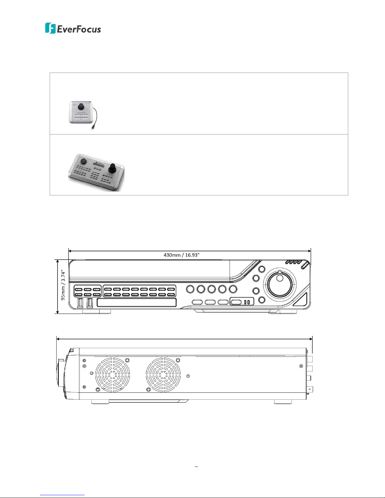
1.4 Optional Accessories
EKB200 (USB controller keyboard: connect to the PC or DVR to control the PTZ cameras
connected to the DVR). Please refer to 6.9.6 EKB200 Setting in the User Manual of the
EKB200 Keyboard.
• EKB500 (RS-485 keyboard: connect to the RS-485 port to control the PTZ cameras
connected to the DVR). Please refer to User Manual of the EKB500 Keyboard.
1.5 Dimensions
Front View
Side View
7
PARAGON FHD 16x4
1
2
6
3
4
5
7
14
15
16
17
18
19
20
21
13
8
9
10 12
11
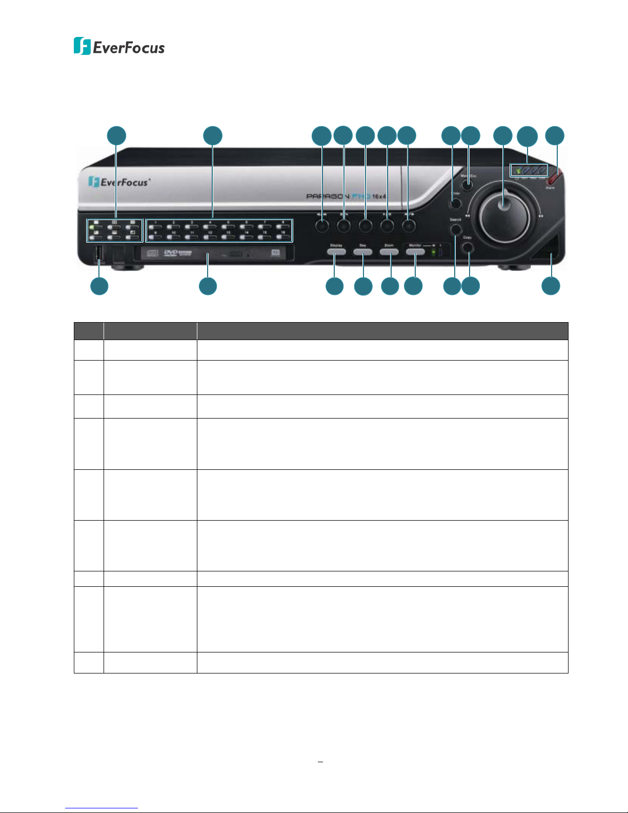
1.6 Front Panel
No. Name Description
1 Screen Layout Press the type of layout you want for displaying your channel feeds.
2
Channel
1~16
Press to display the channel in full screen. The LED indicates the
channel is displayed in full screen.
3 Fast Reverse Press to play the recorded data in fast reverse.
Press to play the recordings in reverse at normal speed. Press this
button again to Pause the reverse playback. Press the Stop button to
stop all playback actions and exit the playback area.
4
Reverse
Play/Pause
Press to stop either the Reverse, Fast Reverse, Play, or Fast Forward
5 Stop
functions, if that function is active. This button stops all Play functions,
but no Recording functions.
Press to play the recordings forward. Press this button again to Pause
6 Play/Pause
the playback. Press the Stop button to stop all playback actions and exit
the playback area.
7 Fast Forward Press to play the recorded data in fast forward.
Use this button in conjunction with the Menu/Esc button (9) and the
8 Enter
Jog / Shuttle Wheel (10) to select menu values or to scroll between
menu categories. You can also use it in conjunction with a mouse or
you can use only a mouse to do these functions.
9 Menu/Esc Press to enter/exit the Main Setup Menu.
8
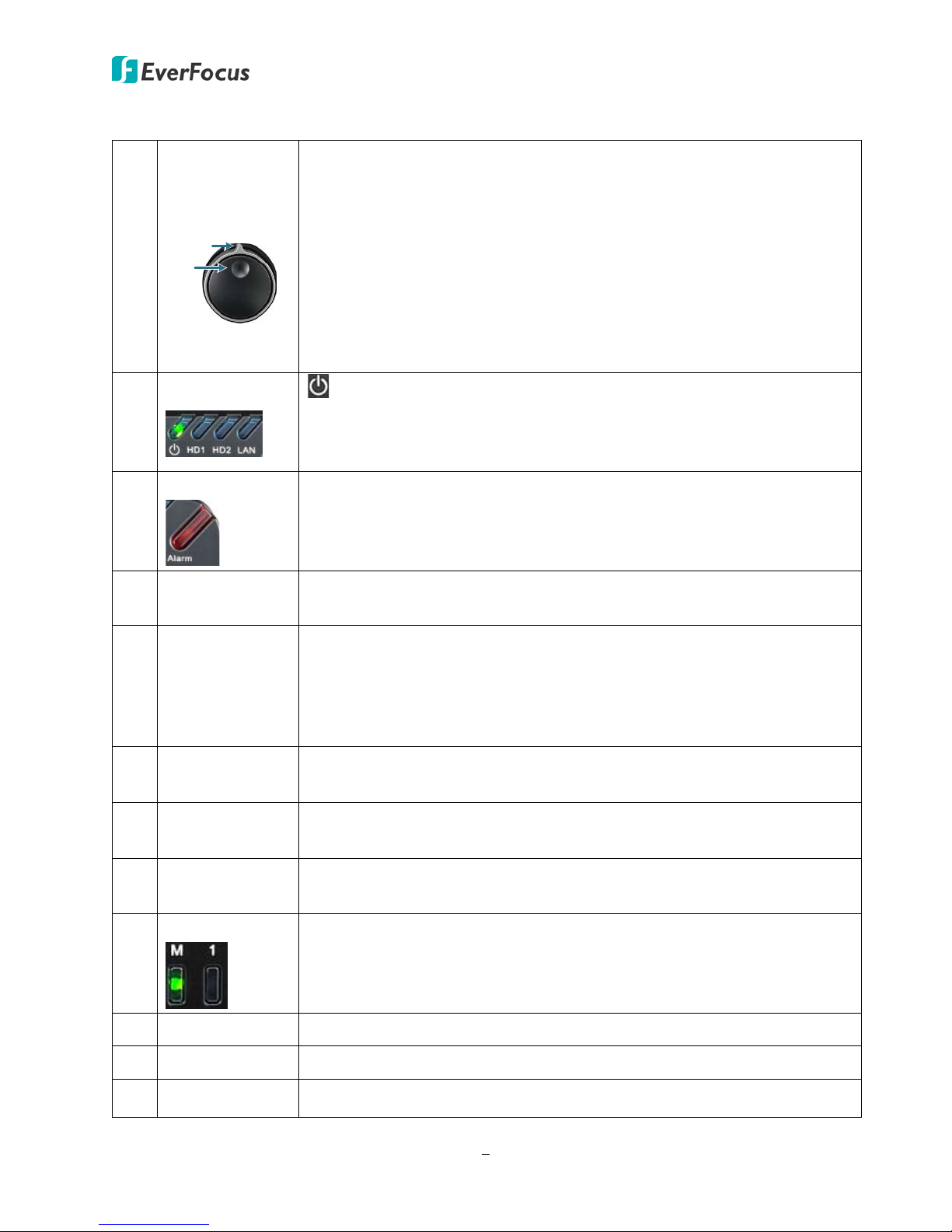
10
Jog
Shuttle
PARAGON FHD 16x4
Jog / Shuttle
Wheel
Use the Shuttle (outer wheel) to:
• In Playback mode, use the Shuttle wheel for fast forward / fast
reverse.
• Switch between Menu options / parameters.
• Highlight individual cameras.
Use the Jog (inner wheel) to:
• In Pause mode, use the Jog to move frame by frame.
• Switch between Menu options / parameters.
• Highlight individual cameras.
Status LED
11
Alarm
12
13 USB2.0 Port
DVD Burner
14
(Optional)
15 Display
16 Seq (Sequence)
: Indicates the power is on.
HD1: Indicates the internal Hard Disk is activating.
HD2: Indicates the external Hard Disk is activating.
LAN: Indicates the DVR is connected to the network.
Indicates an alarm input is triggered.
The USB2.0 port for connecting to a mouse, external storage device or
EKB200 keyboard.
Use the DVD Burner for archiving the recordings from the DVR. It’s
highly recommended to use a DVD with 4x or higher speed disc for
recording. To open the DVD tray, please refer to 4.8 Archiving the
Recordings or Log Data to the USB or DVD. To close the tray, just gently
push it and it will be automatically closed.
Press to cycle between the info display types (channel and status bar
info).
Press to enter the automatic sequence mode. This will show each
channel feed in sequence. Press again to exit sequence mode.
17 Zoom
Press repeatedly to toggle between 2x and 4x zoom. Press the
Menu/Esc button to switch zoom off.
Monitor
18
Press to switch between the Main and Call monitors. Just remember to
exit the setup menus before doing so.
19 Search Press to enter the Search Setup menu.
20 Copy Press to enter the Copy Menu.
21 IR Receiver Receiver for signals from the IR remote control.
9

PARAGON FHD 16x4
6
1
2
3 4
5
7 8 9
10 11
12
13
14
1.7 Rear Panel
No
Name Description
1 Power Port Connects to the 100-240 VAC~ power using the supplied Power Cord.
2 Power Switch Press to turn on or off the power.
Connects up to 16 alarm inputs and 4 alarm outputs devices. You can
3 Alarm Input /Out
also connect to the radio-controlled clock for time synchronization.
Please refer to 2.3.2 Alarm I/O.
Connects to the audio input devices such as microphones using the
4 Audio Input 1~16
supplied Audio Cable. Note that the microphone with a (built-in)
amplifier and external power supply is required.
Loop Video Output
5
1~16
You can also optionally connect the monitors to each Loop Video
Output to display the video of the corresponding channel. Please
refer to 2.3.1 Monitor Connection.
6 eSATA Port Connects to an external eSATA storage device.
Connects to analog HD / SD cameras using coaxial cables.
Note:
1. The DVR can automatically configure itself as NTSC or PAL. To
do this, connect a camera to any channel of the DVR. The DVR
will detect the first connected camera format (NTSC or PAL) and
then automatically configure itself to the detected format from
7 Video Input 1~16
the first connected camera. For example, if the format of the
first connected camera is NTSC, the DVR will configure itself to
NTSC format.
2. All video inputs are compatible with all resolution types of
cameras, such as 1080p, 720p, 960H and D1 cameras (HD-TVI /
HD-CVI / HD-SDI cameras are not supported).
10

Audio Outputs
Connects to the audio output devices, such as speakers. Note that the
8
(RCA)
PARAGON FHD 16x4
speaker with a (built-in) amplifier and external power supply are
required.
9 CVBS Port (BNC)
10 HDMI Port
This can be used as a Call monitor output. Connects to the monitor
using a BNC cable (see 2.3.1 Monitor Connection).
This can be used as a Main monitor output. Connects to the monitor
using a HDMI cable (see 2.3.1 Monitor Connection).
11 RS-485 Port Connects to the RS-485 device (EKB500) or PTZ camera.
12 USB2.0 Port
The USB2.0 port for connecting to a mouse, external storage device
or EKB200 keyboard.
13 Ethernet (LAN) Connects to the Network.
14 VGA Port
This can be used as a Call monitor output. Connects to the monitor
using a VGA cable (see 2.3.1 Monitor Connection).
11
PARAGON FHD 16x4
2
2. Installation
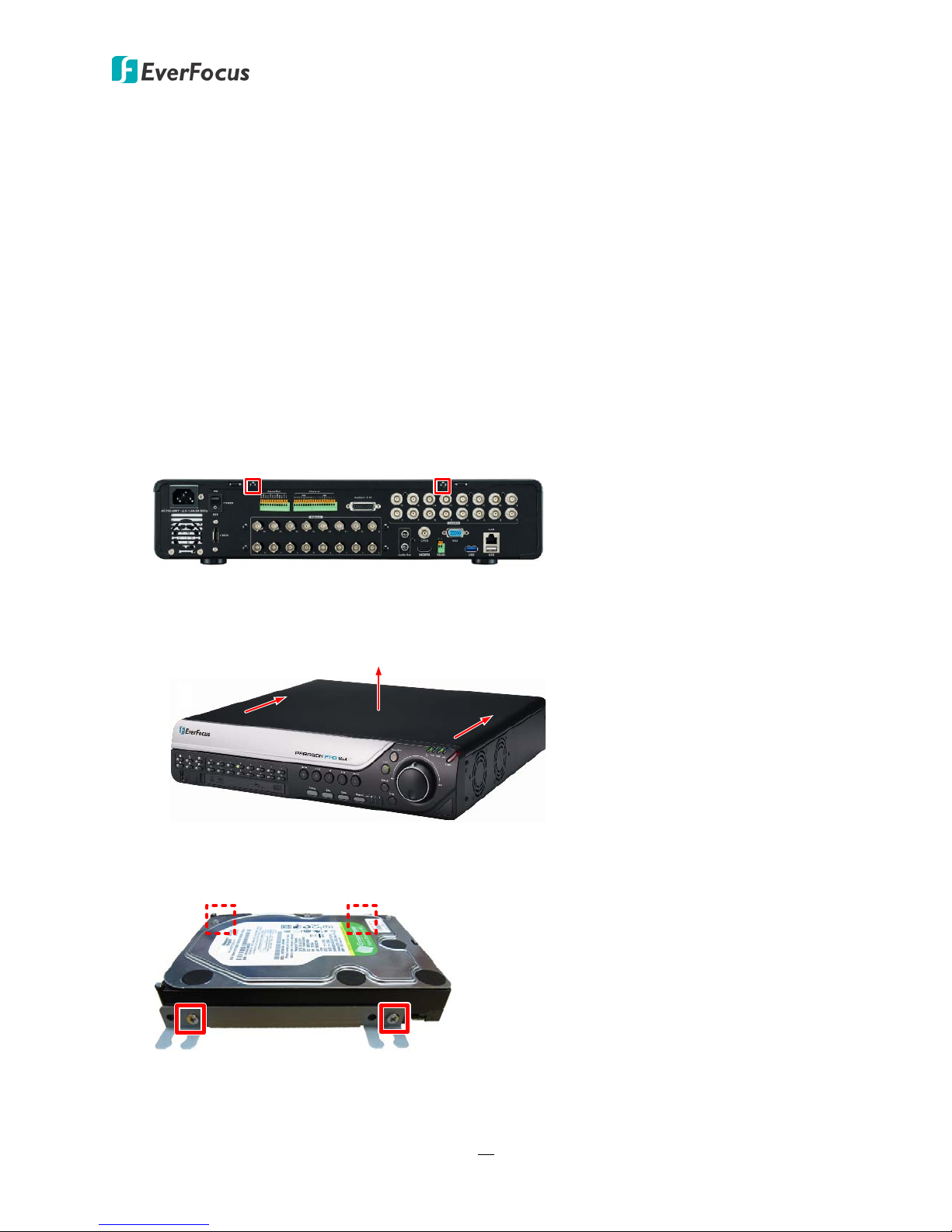
2.1 Hard Disk Installation
You can optionally install four 3.5” HDDs inside the DVR for recording videos.
1. Make sure the DVR is power-off.
2. Unscrew the two housing screws on the back panel of the DVR.
Chapter
3. Push the housing to the back and open it.
4. Fix the two HDD brackets on both side of the HDD using the Silver Screws.
12
PARAGON FHD 16x4
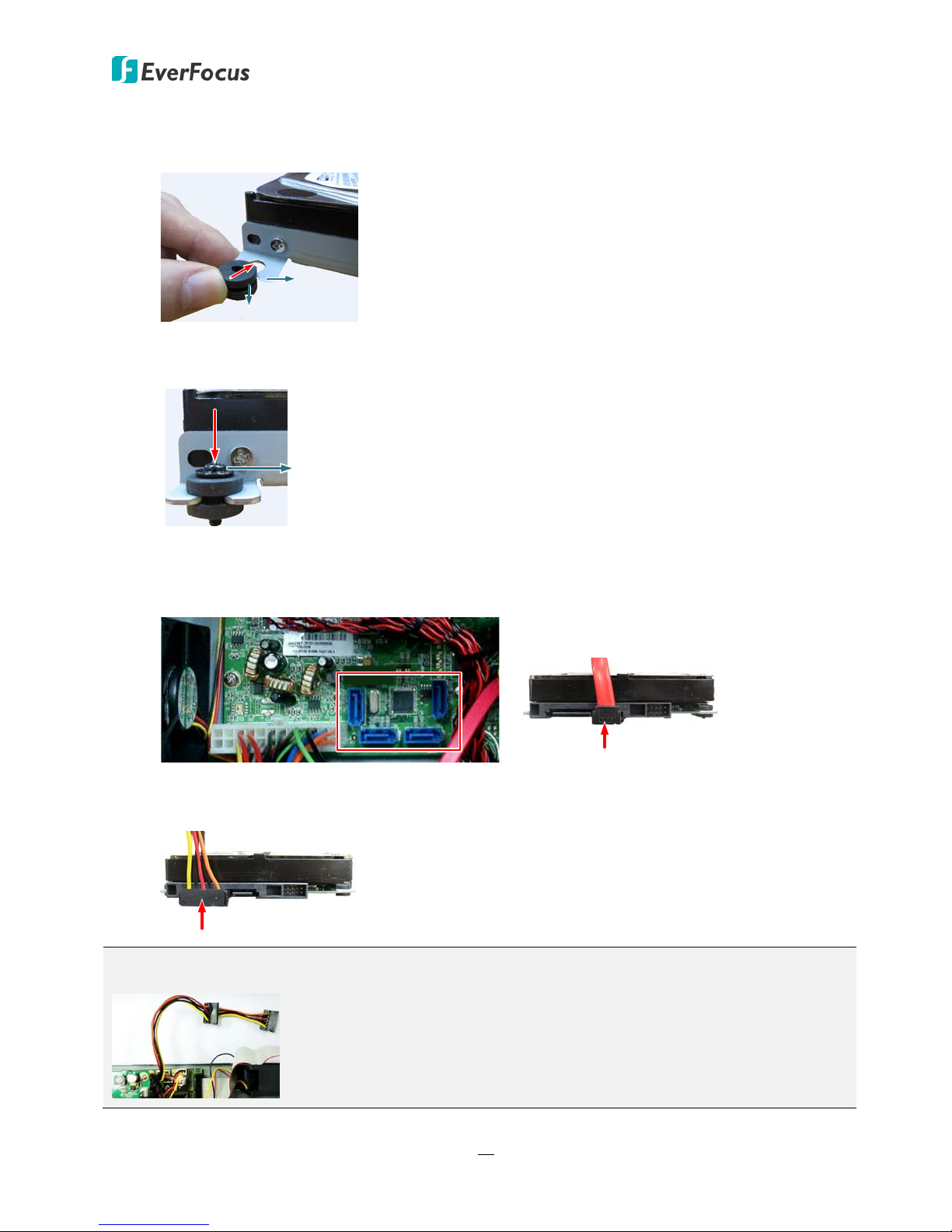
Bracket
Rubber Spacer
Black Long
Screw
5. Push the Rubber Spacer into the bottom slot of Bracket.
6. Insert Black Long Screws into the Rubber Spacers.
7. Use the SATA Cable, and connect one end to either one of the SATA ports on the PCB inside
the DVR, and the other end to the SATA port on the HDD.
8. Connect the internal power cable to the HDD.
Note: The internal power cable is connected to the Main board inside the DVR. The power cable
features two connectors, which can be used to connect to two HDDs.
13
PARAGON FHD 16x4
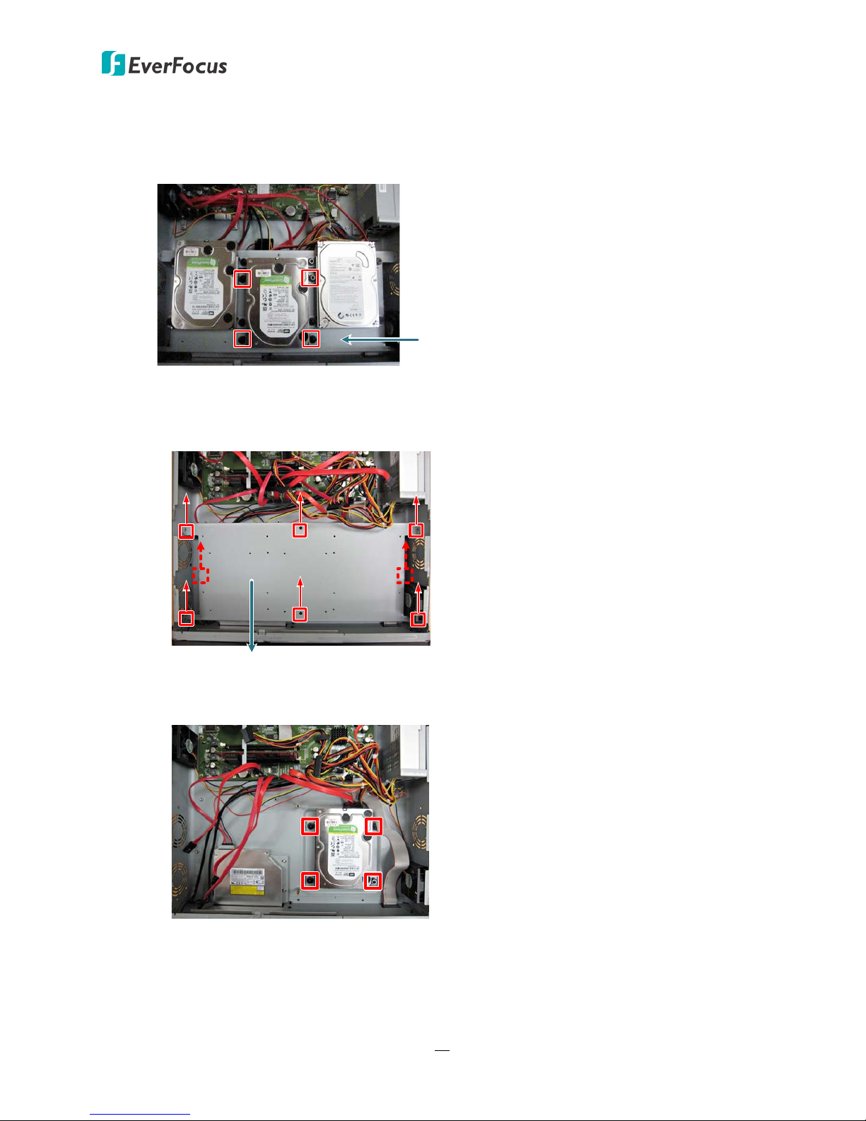
HDD Tray
HDD Tray
9. Screw the HDD with brackets inside the DVR (You can screw up to 4 HDDs).
• If you only need to use one to three HDDs, just screw them on the HDD tray.
• If you need to use four HDDs, you have to screw one HDD under the HDD tray.
a. Unscrew eight screws on the HDD tray first and take the tray out.
b. Screw one HDD at the bottom of the DVR, and screw back the HDD tray.
c. Screw the rest HDDs on the HDD tray.
10. Screw back the housing to the DVR.
14
PARAGON FHD 16x4
2.1.1 Hard Disk Compatibility List
Please go to the PARAGON FHD 16x4 Web page on EverFocus’ website
http://www.everfocus.com.tw to see the latest Hard Disk Compatibility List.
Note: If using two or more hard disks, please choose the hard disks with the same capacity.
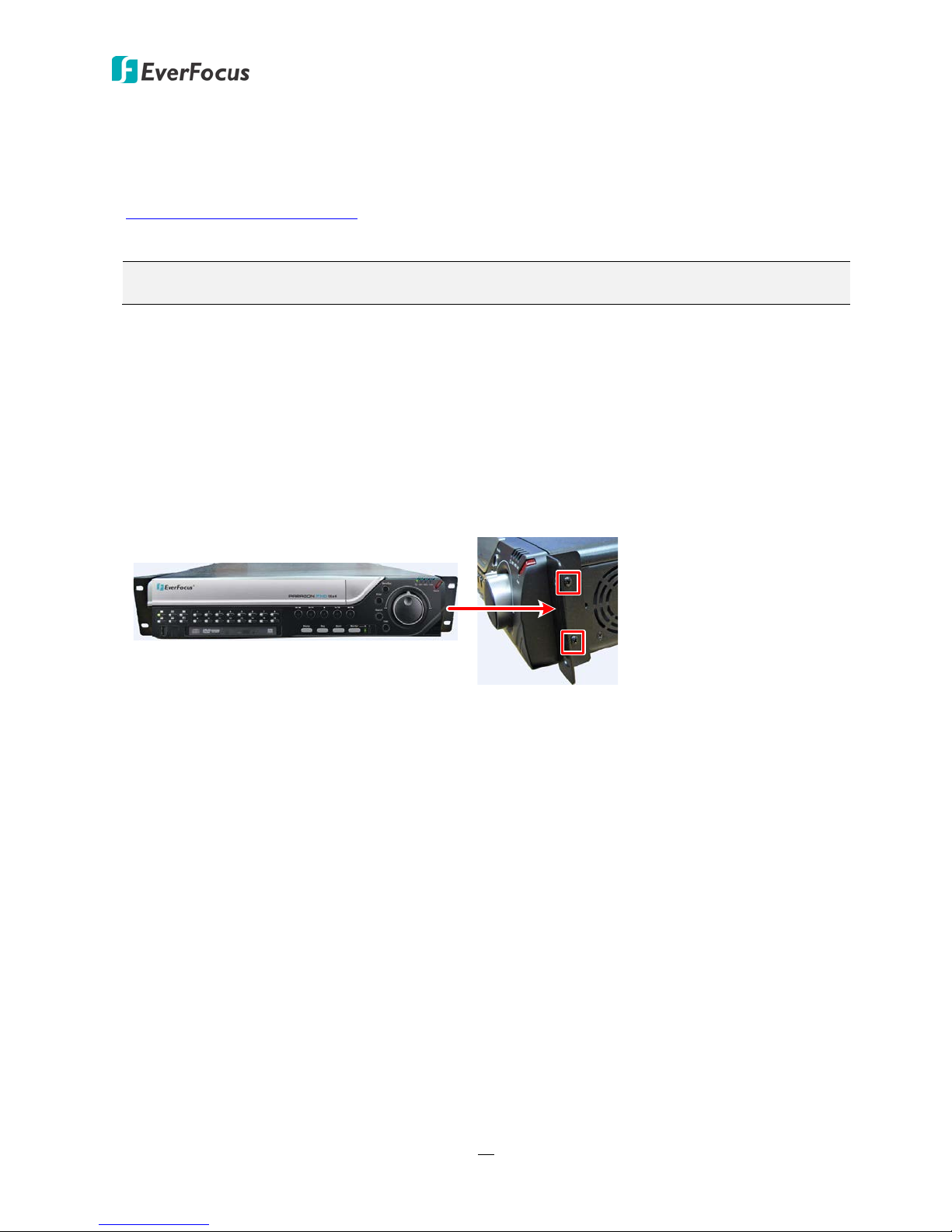
2.2 Rack Mount
To install rack ears on the DVR:
1. Unscrew the four M3 (φ6.8) screws on both side of the DVR.
2. Use the supplied two rack ears and the above screws for rack mount installation on both side.
15
PARAGON FHD 16x4
Web Remote
Client
Camera 1~16
Mouse
3
Power Supply
1
Line Level
Audio Out
Line Level
Audio In 1~16
2
CMS:
Genie XMS
Main Monitor
(HDMI)
Network
5 6
4
7
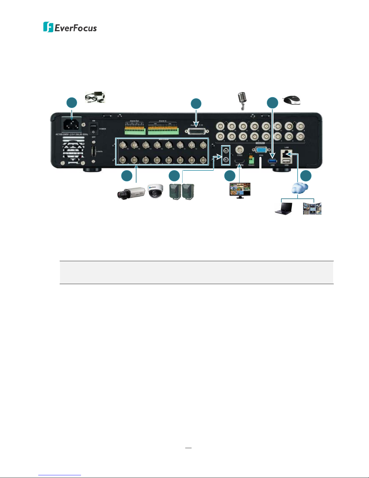
2.3 Basic Connection
The instructions below the figure describe the basic connection for the PARAGON FHD 16x4.
1. Using the supplied Power Cord, connect one end to the 100-240 VAC~ port on the DVR and
the other end to the 100-240 VAC~ power outlet.
Note: Please ensure to connect the internal power cables to the internal HDDs before
powering on the DVR.
2. Connect the line level audio input devices to the DVR using the supplied Audio Cable. Note
that the audio input devices, such as microphones, are required to have a (built-in) amplifier and
external power supply.
3. Optionally connect a mouse to the DVR to control the system. You can also control the
system using the supplied IR Remote Control or the control keys on the front panel.
4. Connect the cameras to the DVR using the coaxial cables. EverFocus eZ.HD cameras are
recommended. (HD-TVI / HD-CVI / HD-SDI cameras are not supported)
5. To listen to audio of video source, connect speakers to the Audio Out port. Note that speaker
with a (built-in) amplifier and external power are required.
6. To view videos, connect a monitor to the HDMI port using the HDMI cable supplied by the
monitor manufacturer.
7. Use a standard RJ-45 cable to connect the DVR to the network for remote viewing or using
EverFocus surveillance system (Genie XMS).
16

PARAGON FHD 16x4
Rear View
Call Monitor
(VGA)
Main Monitor
(HDMI)
Call Monitor
(CVBS)
Loop Video Output
1~16 (BNC)
HDMI
Cable
VGA
Cable
CVBS
Cable
BNC
Cable
2.3.1 Monitor Connection
Connect the monitor to the CVBS, HDMI or VGA port on the rear panel of the DVR. The PARAGON
FHD 16x4 DVR provides 1 main monitor output (HDMI); and 2 call monitor outputs (VGA and BNC)
with identical functionality.
The main monitor output can deliver full HD output resolution (1920x1080, progressive, 60 Hz.
vert., 68 KHz hor.). The 2 call monitors can display camera streams or perform sequence display
mode. Both of the 2 call monitor outputs provide the identical functionality and can be operated
simultaneously. Make sure that the connected monitor's specifications comply with the resolution
requirements. To configure the monitor setting, please refer to 6.6 Display Setting.
You can also optionally connect the monitors to each Loop Video Output to display the video of
the corresponding channel.
Note:
1. The connected monitors’ specifications must comply with the resolution requirements.
2. Do not exceed the max. HDMI cable length of 15 meters. The standard HDMI cables can
support cable length up to 3 meters. For longer distances, such as 15 meters, it is highly
recommended to use high quality HDMI cables.
17
PARAGON FHD 16x4
Alarm
Radio-controlled Clock
ALMIN
GND
ALMIN
GND
Alarm Input with N.O. contact in idle state Alarm Input with N.C. contact in idle state
ALMOUT +
ALMOUT -
ALMOUT +
ALMOUT -
Alarm Output with N.O. contact Alarm Output with N.C. contact
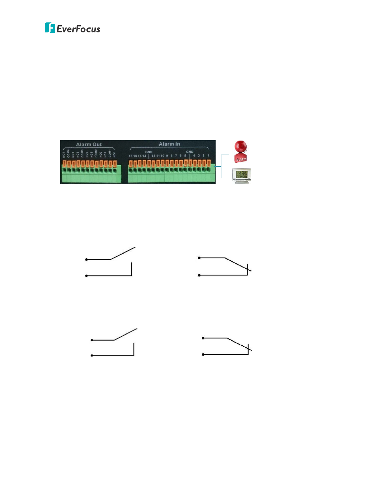
2.3.2 Alarm I / O
The DVR provides 16 alarm inputs and 4 alarm outputs. You can also connect the
radio-controlled clock to the alarm input of the DVR for the time synchronization. The DVR
supports the radio-controlled clock which will automatically synchronize to the time standard
so that you won’t need to reset the time manually. For radio-controlled clock connection,
connect the positive (+) wire to either port of Alarm Input 1~4 and negative (-) wire to the
GND port.
Alarm Input Contacts
This DVR provides one alarm input per camera. All inputs are programmable N.O. (Normal
Open) or N.C. (Normal Closed). All settings are programmed in the ALARM / Event menu.
Alarm Output Contacts
The relay output provides either Normally Open or Normally Closed dry contacts.
18
PARAGON FHD 16x4
Rear View
RS-485 Port
PTZ Camera 1~16
EKB500 Keyboard
RS-485 Cable
Coaxial Cable
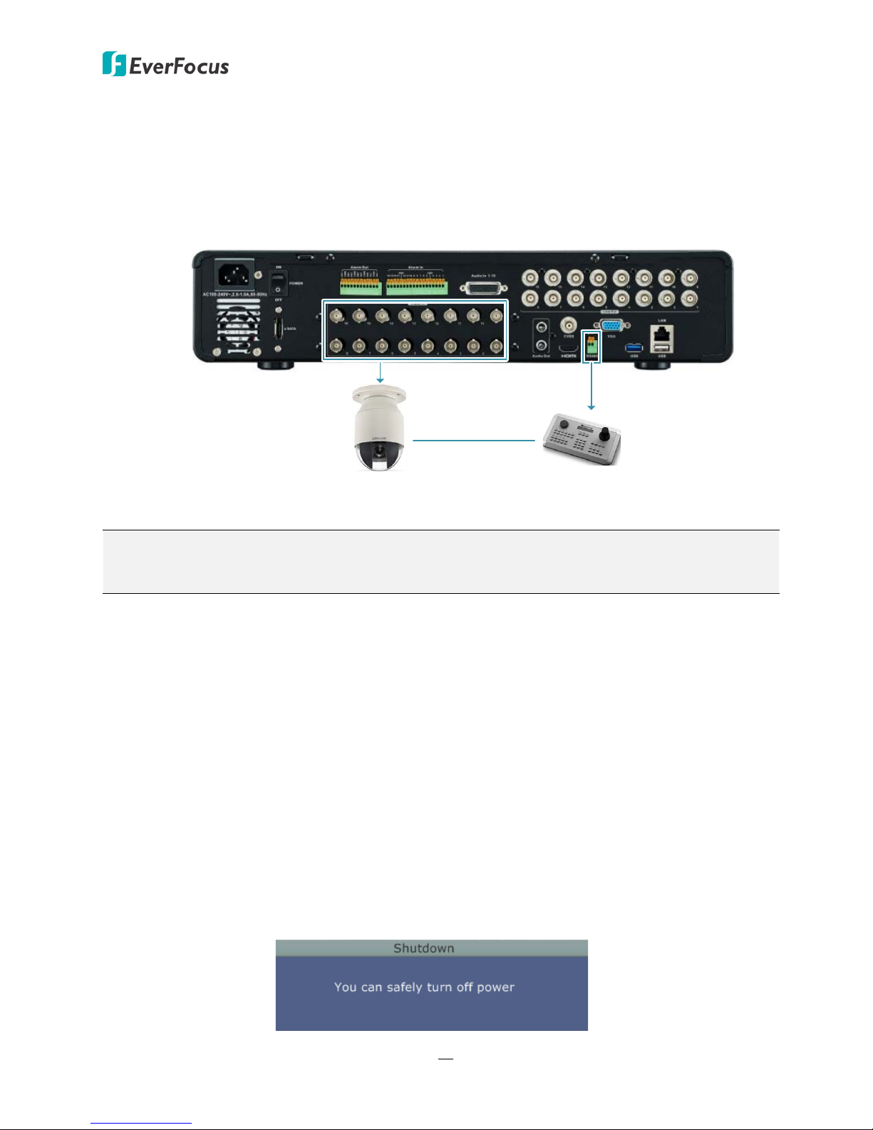
2.3.3 RS-485 Port
The RS-485 port, located on the rear panel of the DVR, can be used to connect to an RS-485
keyboard for controlling PTZ cameras or simply connect to a PTZ camera or connect to a POS
device.
Note: EverFocus FHD series DVR supports the eZ.Controller function, which enables users to
control PTZ camera from DVR using only a coaxial cable without the need of a RS-485 cable
between the PTZ camera and the DVR (see 1.2 eZ. Controller Function Description).
2.4 Turning On / Off the Power
Before powering on the DVR, please make sure the internal HDDs have been installed properly.
Once you have completed the basic cable connections, you are ready to turn on the DVR.
To turn on the power, connect the supplied Power Cord to the power outlet and turn on the
Power Switch. All of the LED indicators on the front panel will light up. The DVR will automatically
run an internal process, when the process is complete, the LED indicators will turn off, and the
POWER LED will remain light up in green. And then you can start operating the DVR.
To turn off the power, please go to OSD Root Menu > System Setting > Miscellaneous setting page,
and click Shutdown (refer to 6.9.7 Miscellaneous). After the message pops up as below, you can
now turn the Power Switch to the "Off" position.
19
PARAGON FHD 16x4
2.5 Checking the Dynamic IP Address
You can look up the IP address and access the Web interface of the DVR using the IP Utility (IPU)
program, which can be downloaded from EverFocus’ Website:
http://www.everfocus.com/HQ/Support/DownloadCenter_p1.aspx. Please connect the DVR in the
same LAN of your computer.
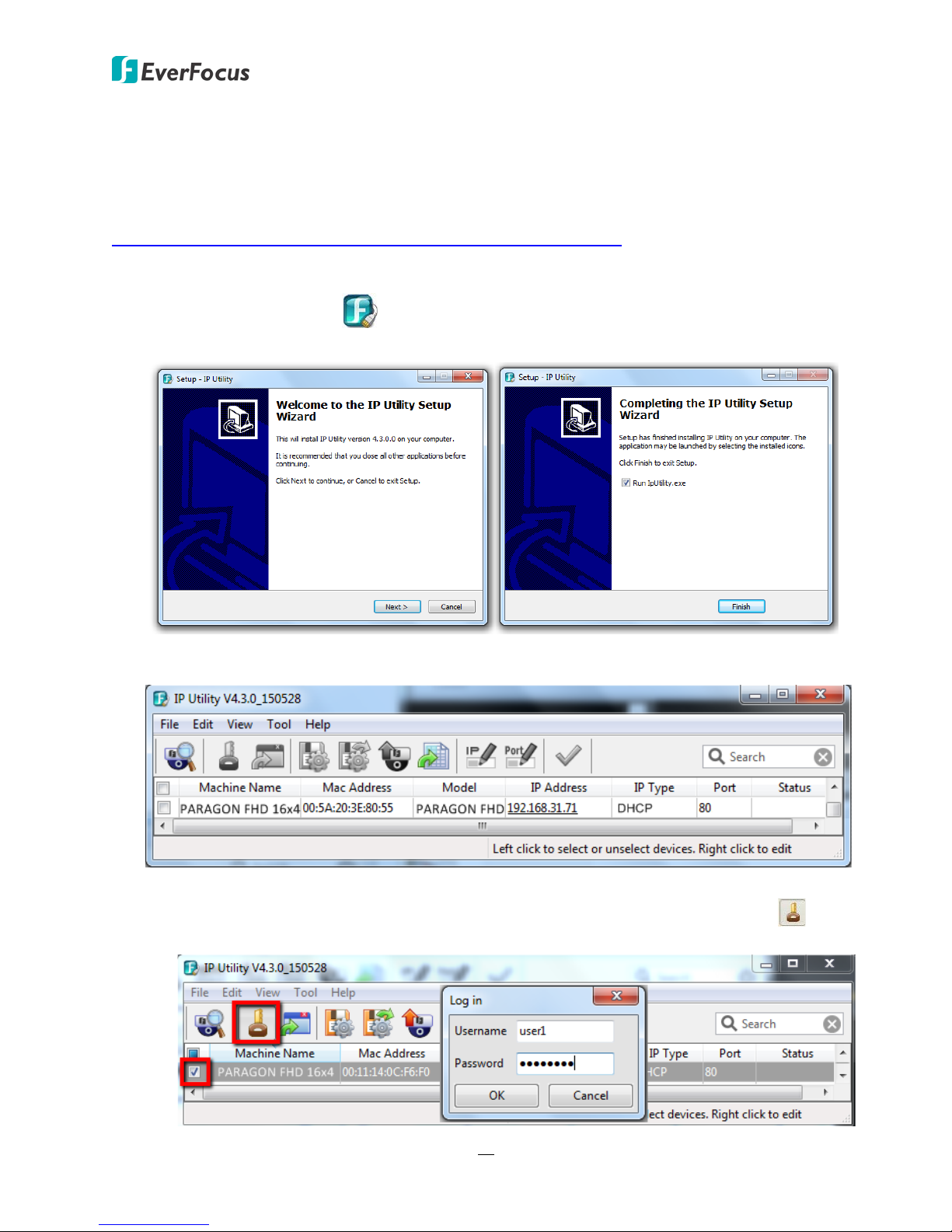
1. Save IP Utility Setup.exe in your computer. Double click the .exe file and follow the
on-screen instructions to install the IP Utility.
2. Click the Finish button, the IP Utility will be automatically launched to search the IP devices
connected on the same LAN.
3. To optionally configure the Machine Name, IP Address, IP Type or Port Number using the IPU:
a. Log in the mobile DVR by checking the desired model and then click the Log in icon.
The Log in dialog box appears.
20
PARAGON FHD 16x4
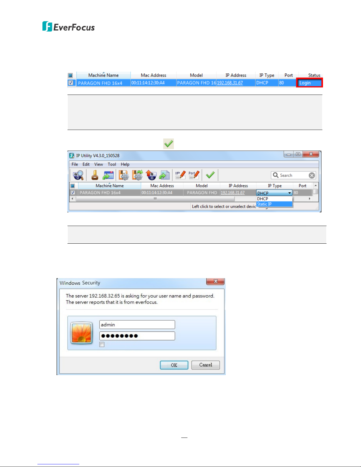
b. Type the Username and Password. Click the OK button, the status of the selected camera
will display Login.
Note:
1. The default user ID is admin and the default password is 11111111.
2. If you select more than one mobile DVRs that have the same user ID / password,
you will be able to log in several mobile DVRs at once.
c. Right click the columns (such as Machine Name, IP Address, IP Type or Port) to configure
the setting. Click Apply Changes button to apply and save the settings.
Note: Most networks uses DHCP to assign IP address, if you are unsure of your network
settings, please consult your network administrators for configuration details.
4. To access the Live View window, double click the IP address of the desired device, the login
window pops up. Type the user ID and password to log in. By default, the user ID is admin and
the password is 11111111.
21
PARAGON FHD 16x4
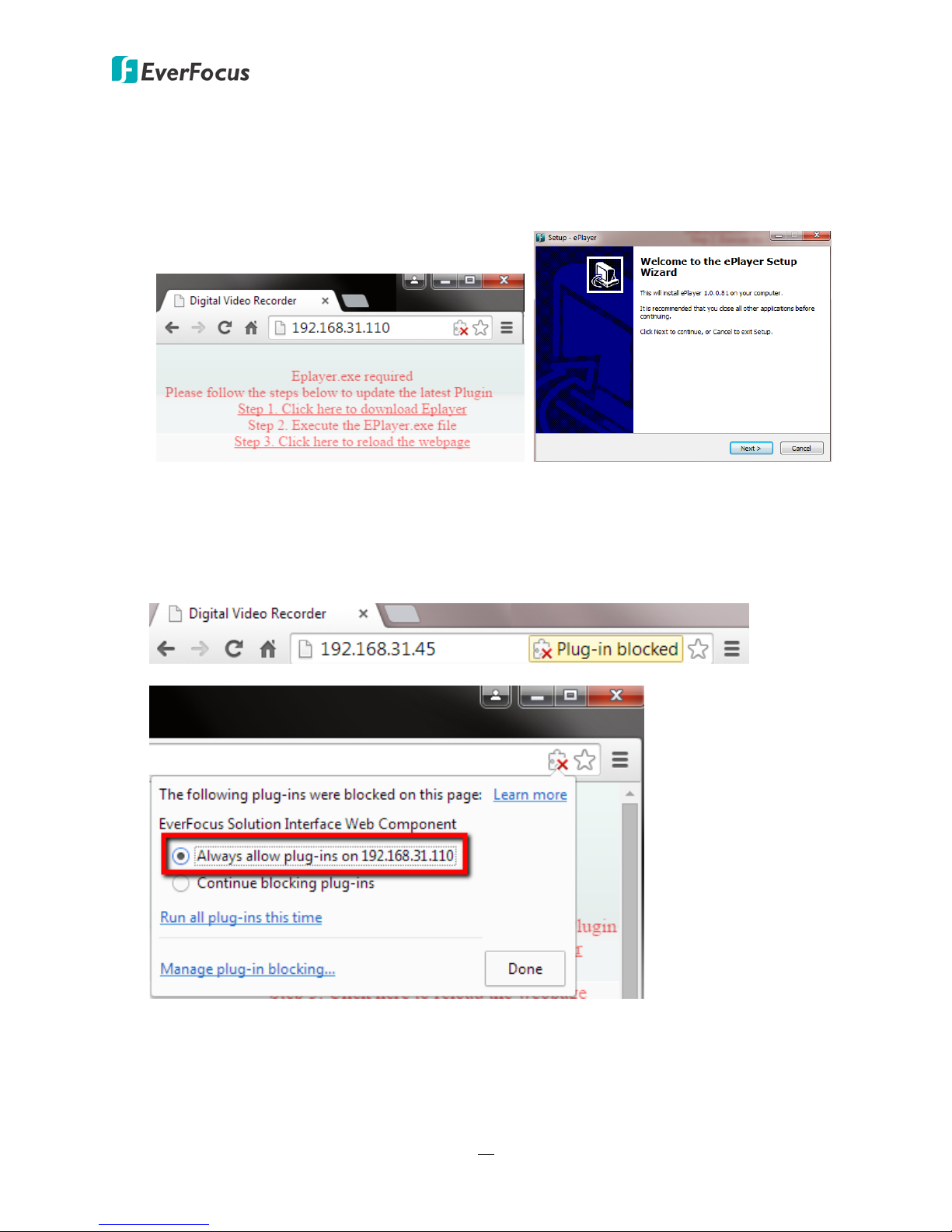
5. If you log in for the first time, follow the instruction steps on the interface to update the latest
Plugin version (ePlayer). After reloading the webpage, the login window pops up again. Type
the user ID and password to log in again. By default, the user ID is admin and the password is
11111111.
Note for the first time login:
The “Download ePlayer Instruction” page will only be prompted for the first time login in
order to update the system to the latest plugin version.
When the Plug-in blocked appears on the browser, select Always allow plug-ins on xxx, click
Done and then reload the webpage.
6. Now you will be able to see the remote live page.
22
 Loading...