

Page 1
ii
NVR8008X Enterprise Rack Mount NVR
8-Bay, up to 100-Channel Megapixel Recording, RAID Storage
Quick Installation Guide
Copyright © EverFocus Electronics Corp,
Release Date:December, 2014
Notice: The content is subject to change without notice.
Page 2
NVR8008X Enterprise Rack Mount NVR
1
1. Introduction
EverFocus NVR8008X is an enterprise-level NVR, supporting scalable channel numbers from 64 up
to 100 channels. Featured with 8-bay hot swappable SATAIII HDDs and RAID 0,1,5,6,10functionality
with the highest data protection, the NVR8008X is able to record at 250 Mbps in speed with
approximately64 channels working simultaneously at 2-megapixel / 30 fps with H.264 codec
without remote playback.
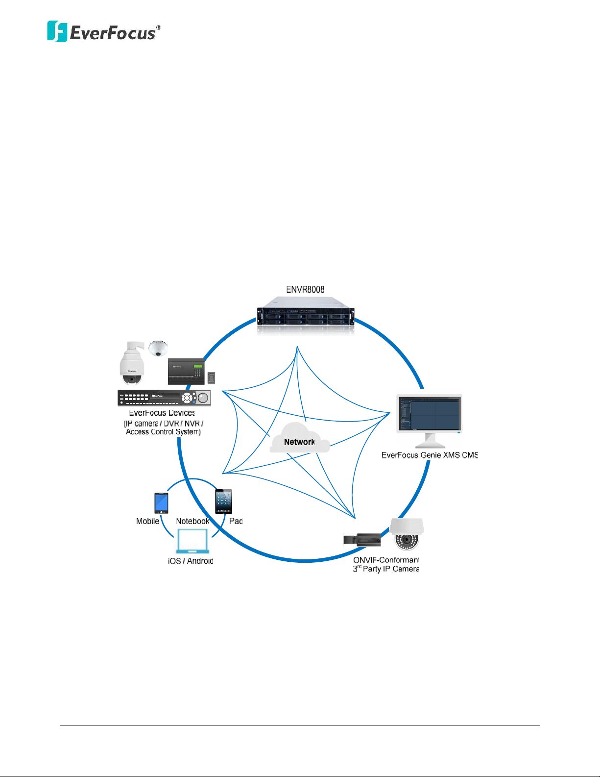
Operating on a Linux-based system, the NVR8008Xprovides a storage capacity of up to 32 TB (4 TB
per drive),and is compatible with all EverFocus devices such as IP cameras, DVR, NVR, access
control systems and EverFocus CMS software, Genie XMS. The ONVIF-conformant 3rd-party
cameras can also be connected to the NVR. Industry standard video compression formats, such as
H.264, MPEG4 and M-JPEG (depends on IP cameras) are all supported.The NVR8008X is also
supported by EverFocus MobileFocus apps on iOS and Android devices extendingvideo surveillance
from fixed locations to mobile environments.
1.1 Supporting Operating Systems and Browsers
Operating System: Microsoft Windows XP (32-bit)/ 7 (32/64-bit)/ 8 (32/64-bit)
Web Browsers: Google Chrome
Page 3
NVR8008X Enterprise Rack Mount NVR
2
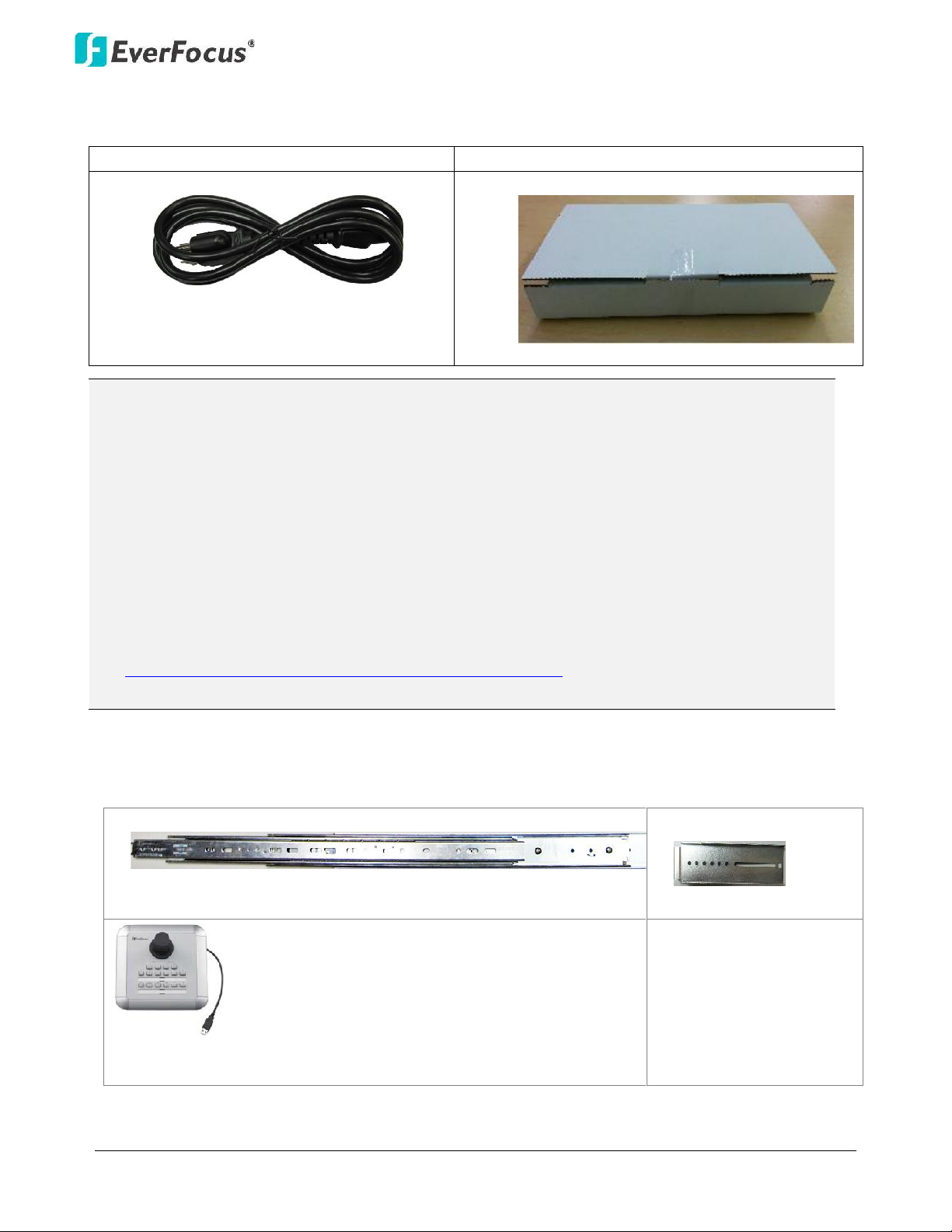
1.2 Packing List
NVR8008X x1
Quick Guide x 1
Power Cord x 1
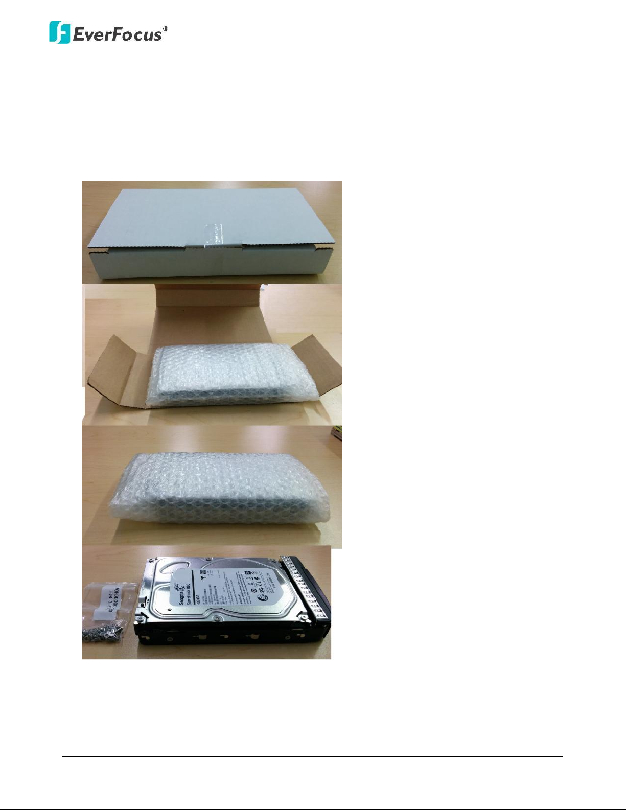
HDD. Packed in white boxes
1.3 Optional Accessories
Rack Mount Rail x 2
Front Bracket x 2
EKB200 (USB controller keyboard: connect to the PC to
control the PTZ cameras connected to the NVR
Note:
1. Any physical damage to the NVR due to improper installation or handling will not be
covered under warranty.
2. Every install environment is different. RAIL MOUNTS are not included with the NVR. This is
an optional accessory.
3. Equipment configurations and supplied accessories vary by country. Please consult your
local EverFocus office or agents for more information. Please also keep the shipping carton
for possible future use.
4. Contact the shipper if any items appear to have been damaged in the shipping process.
5. The latest version of the manuals is available for download from the E verFocus Website.
This also contains part numbers for optional accessories.
http://www.everfocus.com/product.cfm?productid=1855
Page 4
NVR8008X Enterprise Rack Mount NVR
3
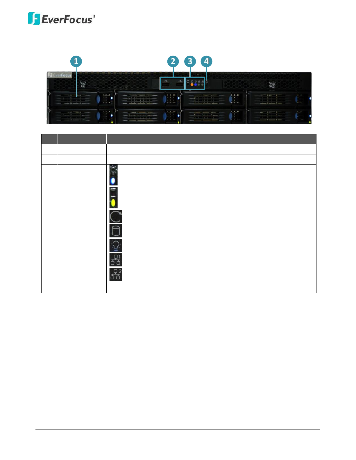
1.4 Front Panel
No.
Name
Description
1
HDD Tray
Pull the HDD tray out to install the HDD.
2
USB
2 USB2.0 ports for connecting to a mouse or external storage device.
3
Status LED
Power: Indicates the HDDs are installed.
HDD R/W: Indicates the HDDs are reading/writing data.
Reset: Use a paper clip to press the reset button.
HDD: Indicates the internal HDD 1~8 is activating.
Power: Indicates the power is on.
LAN1: Indicates the NVR is connected to the network.
LAN2: Indicates the NVR is connected to the network.
4
Power
Press to turn on / off the NVR.
Page 5
NVR8008X Enterprise Rack Mount NVR
4
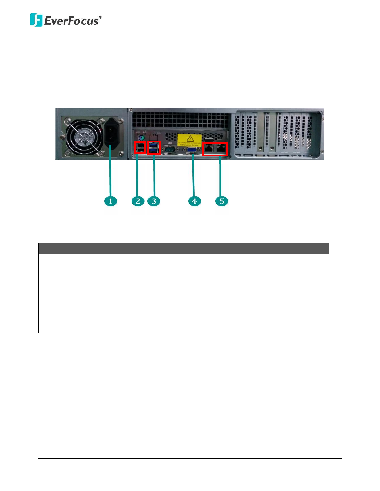
1.5 Rear Panel
No.
Name
Description
1
Power Port
Connects to the 100-240 VAC~ power using the supplied Power Cord.
2
USB2.0 Port
Two USB2.0 ports
3
USB 3.0 Port
Two USB3.0 ports
4
VGA Port
Connects to monitor using a VGA cable. For configuration purpose
only. Not for live view of IP camera.
5
Network
Connects to the network using a standard RJ-45 CAT5 10/100Mb
Ethernet cable. Connects to a router or switch for connecting IP
cameras using a standard RJ-45 CAT5 10/100Mb Ethernet cable.
Page 6
NVR8008X Enterprise Rack Mount NVR
5
2. Installation
Hard Disk Drive Installation
1. Open the white boxes containing the hard drive.
Page 7

NVR8008X Enterprise Rack Mount NVR
6
2. Open the HDD tray by pressing the blue button.
3. Insert the HDD tray into the NVR and push back the black panel to close.
Page 8

NVR8008X Enterprise Rack Mount NVR
7
2.1.1 Hard Disk Compatibility List
Please use the hard disk models recommended in the list below to ensure your hard disks will be
compatible.
SATA Hard Disk
Model
Capacity
Seagate
CE-Video SATA3 / ST1000VM002
1TB
CE-Video SATA3 / ST2000VM003
2TB
CE-Video SATA3 / ST3000VM002
3TB
CE-Video SATA3 / ST4000VM000
4TB
SV35 SATA6 7200/ ST4000VX000
4TB
SV35 SATA6 7200/ ST1000VX000
1TB
SV35 SATA6 7200/ ST2000VX000
2TB
SV35 SATA6 7200/ ST3000VX000
3TB
Constellation CS SATA3 7200 / ST1000NC000
1TB
Constellation CS SATA3 7200 / ST3000NC000
3TB
CE-Video SATA6 5900RPM / ST1000VM002
1TB
CE-Video SATA6 5900RPM / ST2000VM003
2TB
SV35 SATA3 7200/ST3000VX000
3TB
SV35 SATA3 7200/ST2000VX000
2TB
SV35 SATA3 7200/ST1000VX000
1TB
Toshiba
MD03ACA200V 2TB SATA 7200RPM 64MB
2TB
MD03ACA300V 3TB SATA 7200RPM 64MB
3TB
MD03ACA400V 4TB SATA 7200RPM 6MB
4TB
Western Digital
WD40PURX-64GVNYO
4TB
WD30PURX-64P6ZY0
3TB
WD20PURX-64P6ZY0
2TB
WD10PURX-64D85Y0
1TB
Note: If using two or more hard disks, please choose the hard disks with the same capacity.
Page 9

NVR8008X Enterprise Rack Mount NVR
8
2.2 Basic Connection
The instructions below describe the basic connection for NVR8008X.
Before powering on the NVR, make sure the internal HDDs have been installed
properly. When you have completed the basic cable connections, you are ready to
turn on the NVR.
This NVR has dual network ports. It is recommended to separate your IP-camera network from your other network.
The diagram below is an example of an initial network set up.
Page 10

NVR8008X Enterprise Rack Mount NVR
9
Once NVR and IP camera configuration is complete, the DHCP Server/Router and
PC-1 can be removed from the Camera Network.
Page 11

NVR8008X Enterprise Rack Mount NVR
10
Accessing the NVR
To turn on the power, connect the supplied Power Cord to the power outlet and turn on the Power
Switch. After hearing 1 beeps from the NVR, you can start operating. The power LED indicators will indicate operation
status of the HDDs, power, and network. To turn off the power, press the Power Switch on the front panel for a few
seconds before unpluggingthe Power Cord.
You can look up the IP address and access the Web interface of the NVR using the IP Utility
(IPU)program, which can be downloaded from EverFocus’ Website:
http://www.everfocus.com/
1. Save IP Utility Setup AutoRun.exe in your computer. Double click the .exe file and
followthe on
‐screen instructions. Check
Run IPUtility.exe and click the Finish button, the IP
Utility willbe launched to search the IP devices connected in the same LAN automatically .
2. To optionally configure the Machine Name, IP Address, IP Type or Port Number using the IPU :
a. Log in the NVR by checking the desired model and then click the Log in icon. The Log
in dialog box appears.
Page 12

NVR8008X Enterprise Rack Mount NVR
11
b. Type the Username and Password. Click the OK button, the status of the selected camera
will display Login.
Note:
1. The default user ID is admin and the default password is 11111111.
2. If you select more than oneNVRs that have the same user ID / password, you will
be able to log in severalNVRs at once.
c. Right click the column to configure the setting. Click Apply Changes button to apply
and save the settings.
Note: Most networks uses DHCP to assign IP address, if you are unsure of your network
settings, please consult your network administrators for configuration details .
Page 13

NVR8008X Enterprise Rack Mount NVR
12
3. To access the Live View window, open a Google Chrome Web browser, type the IP address of
the NVR in the address field and press the Enter key on the keyboard, the Welcome window
appears. Follow the instruction steps to update the latest Plugin version.
Note:The Welcome window will only be prompted for the first time login in order to update
the system to the latest plugin version.
4. After reloading the webpage, the login window is displayed again. Type the user ID and
password to log in. By default, the user ID is adminand the password is 11111111.
Page 14

NVR8008X Enterprise Rack Mount NVR
13
5. Click the Login button, the Live View window (see 3.2 Live View Windowof the User’s Manual)
appears.
6. To log out the system, click the Logout button on the upper-right corner of the Live View
Window.The system will return to the login window.
Page 15

NVR8008X Enterprise Rack Mount NVR
14
2.3 Live View Window
No.
Name
Description
1
List
Click to display the Device List
2
Menu Tree
Click to show / hide the Menu Tree of the Device List.
3
Group
Click to configure the Group settings (see 3.2.3.1 Group
Settingsof the User’s Manual).
4
Ratio
Click to switch live video ratio between original (source video)
and extended (to the layout screen).
5
eMap
Click to display the eMap (see 3.2.1 eMap of the User’s Manual).
6
OSD Display Mode
Click to show / hide the information of device name and time.
7
Expand / Collapse
Click to expand or collapse the Device List.
8
Full Screen
Click to display the Live View layout in full screen.
9
Option
Click to show/hide the Live View ToolBar at the bottom of each
cell. See 3.2.2 Live View Tool Barof the User’s Manualfor more
details.
Page 16

NVR8008X Enterprise Rack Mount NVR
15
10
Device Detail
Click to enter the Device List setup page (see 3.2.3 Device List
Setupof the User’s Manual).
11
Live View
Click to display the Live View layout.
12
Playback
Click to enter the playback page for multi-channel playback.
13
Close Stream
Click to disconnect the live streams.
14
Event List
Click to enter the Event List setup page.
15
Access List
This function is optional. Click to enter the Access Control setup
page.
16
IVS
This function is optional. Click to enter the Intelligent Video
Surveillance (IVS) setup page.
17
Setting
Click to enter the Settings page (see 3.5 Setting of the User’s
Manual).
18
Add
Click to save the current live layout as a Page in the Page List
(see 3.2.5 Page Setting of the User’s Manual).
19
Logout
Click to log out the system.
20
Theme Switch
Click to switch the theme between the dark and light.
21
Layout Detail
Click to enter the Layout Design page. You can further create or
modify the personal layout design (see 3.2.4 Layout Setting of
the User’s Manual).
22
Layout
Click to enter the layout page for layout selection (see 3.2.4
Layout Setting of the User’s Manual).
23
PTZ Detail
Click to enter the PTZ setup page.
24
PTZ Control
Click to display the PTZ Control panel.
25
Page Detail
Click to enter the Page setup page (see 3.2.5 Page Settingof the
User’s Manual).
26
Page
Click to display the Page List(see 3.2.5 Page Setting of the User’s
Manual).
27
Time Search
Click to display the Time Search calendar for playback.
28
Digital Zoom / Fisheye
Click to enter the Digital Zoom / Fisheye operation page.
Page 17

EverFocus Electronics Corp.
EverFocus Taiwan:
12F-1, No.79, Sec. 1, Shin-Tai Wu Road,
Hsi-Chih, New Taipei City, Taiwan
TEL: +886 2 2698 2334
FAX: +886 2 2698 3943
www.everfocus.com.tw
marketing@everfocus.com.tw
EverFocus Europe - Germany:
Albert-Einstein-Strasse 1, D-46446
Emmerich, Germany
TEL: +49 2822 93940
FAX: +49 2822 939495
www.everfocus.de
sales@everfocus.de
EverFocus China - Beijing:
Room 609, TechnologyTradeBuilding,
Shangdi Information Industry Base,
Haidian District, Beijing 100085, China
TEL: +86 10 6297 3336~39
FAX: +86 10 6297 1423
www.everfocus.com.cn
marketing@everfocus.com.cn
EverFocus China - Shenzhen:
4F, No. 2, D4 Building, Wan Yelong
Industrial Park, Tangtou Road, Shiyan,
Baoan, Shenzhen, Guangdong 518101, China
TEL: +86 755 2765 1313
FAX: +86 755 2765 0337
www.everfocus.com.cn
marketing@everfocus.com.cn
EverFocus USA - California:
1801 Highland Avenue, Unit A, Duarte, CA91010, USA
TEL: +1 626 844 8888
FAX: +1 626 844 8838
www.everfocus.com
sales@everfocus.com
EverFocus USA - New York:
415 Oser Avenue, Unit S, Hauppauge, NY11788, USA
TEL: +1 631 436 5070
FAX: +1 631 436 5027
www.everfocus.com
sales@everfocus.com
EverFocus Japan:
3F, Kuramochi, Building II, 2-2-3
Koto-Bashi,Sumida-Ku, Tokyo, 130-0022, Japan
TEL: +81 3 5625 8188
FAX: +81 3 5625 8189
www.everfocus.co.jp
info@everfocus.co.jp
EverFocus India:
UBS, 629/1243, 1st Floor, G Block, Behind Teacher’s
Colony,BandraKurla Complex, Bandra (E), Mumbai 400
051, India
TEL: +91 22 67264500
FAX: +91 22 67264518
www.everfocus.in
sales@everfocus.in
EverFocus China - Shanghai:
Room 403, Ruijin Business Center, No.96,
Zhaojiabang Road, Luwan district, Shanghai 200020,
China
TEL: +86 21 6471 2229 / 6471 2291
FAX: +86 21 6471 0566
www.everfocus.com.cn
marketing@everfocus.com.cn
Your EverFocus product is designed and
manufactured with high quality materials
and components which can be recycled
and reused.
This symbol means that electrical and
electronic equipment, at their end-of-life,
should be disposed ofseparately from
your household waste.
Please, dispose of this equipment at your
local community waste
collection/recycling centre.
In the European Union there are
separate collection systems for used
electrical and electronic product.
Please, help us to conserve the
environment we live in!
Ihr EverFocus Produkt wurde entwickelt
und hergestellt mit qualitativ
hochwertigen Materialien und
Komponenten, die recycelt und wieder
verwendet werden können.
Dieses Symbol bedeutet, dass elektrische
und elektronische Geräte am Ende ihrer
Nutzungsdauer vom Hausmüll getrennt
entsorgt werden sollen.
Bitte entsorgen Sie dieses Gerät bei Ihrer
örtlichen kommunalen Sammelstelle oder
im Recycling Centre.
Helfen Sie uns bitte, die Umwelt zu
erhalten, in der wir leben!
P/N: 4605PNRP18B022B
 Loading...