

Page 1
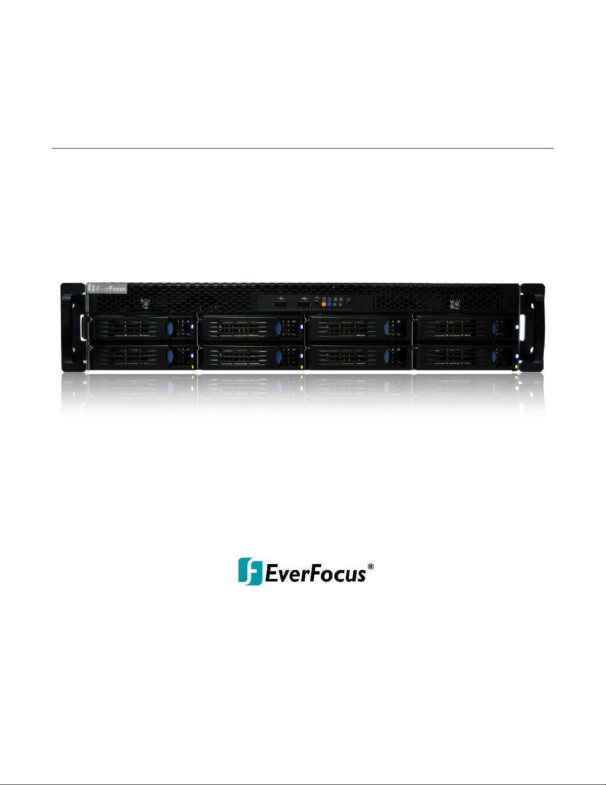
NVR8008X Enterprise Rack Mount NVR
8-Bay, up to 100-Channel Megapixel Recording, RAID Storage
User’s Manual
Copyright © EverFocus Electronics Corp,
Release Date: December, 2014
Notice: The content is subject to change without notice.
Page 2

E V E RF OC U S E L E CT RO N I C S C O R P O R AT IO N
NVR8008X
User’s Manual
1995-2014 EverFocus Electronics Corp
www.everfocus.com
All rights reserved. No part of the contents of this manual may be reproduced or transmitted in any form
or by any means without written permission of the EverFocus Electronics Corporation.
Release Date: December, 2014
QuickTime is a registered trademark of the Apple Computer, Inc.
Windows is a registered trademark of the Microsoft Corporation.
Linksys is a registered trademark of the Linksys Corporation.
D-Link is a registered trademark of the D-Link Corporation.
DynDNS is a registered trademark of the DynDNS.org Corporation.
Other product and company names mentioned herein may be the trademarks of their respective owners.
Page 3

ii
Safety Precautions
It is strongly recommended to use the Local Display only for short-term operation, such as
system configurations. To ensure better system efficiency, the Local Display is not
recommended for long term operation or video monitoring .
Refer all work related to the installation of this product to qualified service personnel or
system installers.
Do not block the ventilation openings or slots on the cover.
Do not drop metallic parts through slots. This could permanently damage the applian ce.
Turn the power off immediately and contact qualified service personnel for service.
Do not attempt to disassemble the appliance. To prevent electric shock, do not remove
screws or covers. There are no user-serviceable parts inside. Contact qualified service
personnel for maintenance. Handle the appliance with care. Do not strike or shake, as this
may damage the appliance.
Do not expose the appliance to water or moisture, nor try to operate it in wet areas. Do
take immediate action if the appliance becomes wet. Turn the power off and refer servicing
to qualified service personnel. Moisture may damage the appliance and also may cause
electric shock.
Do not use strong or abrasive detergents when cleaning the appliance body. Use a dry cloth
to clean the appliance when it is dirty. When the dirt is hard to remove, use a mild
detergent and wipe gently.
Do not overload outlets and extension cords as this may result in a risk of fire or electric
shock.
Do not operate the appliance beyond its specified tempe rature, humidity or power source
ratings. Do not use the appliance in an extreme environment where high temperature or
high humidity exists. Use the NVR at temperatures within 5°C~40°C / 41°F~104°F. The input
power source is 100-240 VAC~ / 500W max.
Read Instructions
All the safety and operating instructions should be read before the unit is operated.
Retain Instructions
The safety and operating instructions should be retained for future reference.
Page 4

iii
Heed Warnings
All warnings on the unit and in the operating instructions should be adhered to.
Follow Instructions
All operating and use instructions should be followed.
Cleaning
Unplug the unit from the outlet before cleaning. Do not use liquid cleaner s, abrasive or
aerosol cleaners. Use a damp cloth for cleaning
Attachments
Do not use attachments not recommended by the product manufacturer as they may
cause hazards.
Water and Moisture
Do not use this unit near water-for example, near a bath tub, wash bowl, kitchen sink, or
laundry tub, in a wet basement, near a swimming pool, in an unprotected outdoor
installation, or any area which is classified as a wet location.
Servicing
Do not attempt to service this unit by yourself as opening or removing covers may expose
you to dangerous voltage or other hazards. Refer all servicing to qualified service
personnel.
Power Cord Protection
Power supply cords should be routed so that they are not likely to be walked on or pinched
by items placed upon or against them, playing particular attention to cords and plugs,
convenience receptacles, and the point where they exit from the appliance.
Object and Liquid Entry
Never push objects of any kind into this unit through openings as they may touch
dangerous voltage points or short-out parts that could result in a fire or electric shock.
Never spill liquid of any kind on the unit.
Battery
There is a risk of explosion if battery is replaced by an incorrect type. Dispose of used
batteries according to the instructions.
a. Use only two AAA dry cell batteries.
b. Do not dispose of the batteries in a fire as it may explode.
Page 5
iv
This Product is RoHS compliant.
ATTENTION! This is a Class A product which may cause radio interference in a
domestic environment; in this case, the user may be urged to take adequate measures.
Federal Communication Commission Interference Statement
This equipment has been tested and found to comply with the limits for a Class B digital
device, pursuant to Part 15 of the FCC Rules. These limits are designed to provide
reasonable protection against harmful interference in a residential installation. This
equipment generates, uses, and can radiate radio frequency energy and, if not installed
and used in accordance with the instructions, may cause harmful interference to radio
communications. However, there is no guarantee that interference will not occur in a
particular installation. If this equipment does cause harmful interference to radio or
television reception, which can be determined by turning the equipment off and on, the
user is encouraged to try to correct the interference by one of the following measures:
•Reorient or relocate the receiving antenna.
•Increase the separation between the equipment and receiver.
•Connect the equipment into an outlet on a circuit different from that to which the
receiver is connected.
•Consult the dealer or an experienced radio/TV technician for help.
FCC Caution: Any changes or modifications not expressly approved by the party
responsible for compliance could void the users’ authority to operate this equipment.
WEEE
The information in this manual was current upon publication. The manufacturer reserves the right
to revise and improve his products. Therefore, all specifications are subject to change without prior
notice. Manufacturer is not responsible for misprints or typographical errors.
Please read this manual carefully before installing and using this unit. Be sure to keep it handy for
later reference.
Your EverFocus product is designed and manufactured with high quality materials and
components which can be recycled and reused. This symbol means that electrical and
electronic equipment, at their end-of-life, should be disposed of separately from your
household waste. Please, dispose of this equipment at your local community waste
collection/recycling centre. In the European Union there are separate collection systems
for used electrical and electronic product.
Please, help us to conserve the environment we live in!
Page 6

v
TABLE OF CONTENTS
1. INTRODUCTION ............................................................................................................. 1
1.1 SUPPORTING OPERATING SYSTEMS AND BROWSERS ................................................................. 2
1.2 PACKING LIST ..................................................................................................................... 2
1.3 OPTIONAL ACCESSORIES ...................................................................................................... 3
1.4 FRONT PANEL .................................................................................................................... 3
1.5 REAR PANEL ...................................................................................................................... 5
2. INSTALLATION ............................................................................................................... 6
2.1 HARD DISK DRIVE INSTALLATION........................................................................................... 6
2.1.1 Hard Disk Compatibility List .........................................................................................................8
2.2 BASIC CONNECTION ............................................................................................................ 9
2.3 CHECKING THE DYNAMIC IP ADDRESS .................................................................................. 11
3. GENERAL OPERATION ................................................................................................. 14
3.1 LOGIN / LOGOUT .............................................................................................................. 14
3.2 LIVE VIEW WINDOW ......................................................................................................... 15
3.2.1 eMap................................ ................................ ...........................................................................17
3.2.2 Live View Tool Bar ...................................................................................................................... 18
3.2.3 Device List Setup......................................................................................................................... 19
3.2.4 Layout Setting ................................................................ ................................ ............................ 24
3.2.5 Page Setting ................................ ............................................................................................... 25
3.3 RECORDING ..................................................................................................................... 26
3.3.1 Setting up the Recording Path ................................................................................................... 27
3.4 QUICK PLAYBACK.............................................................................................................. 28
3.5 SETTING .......................................................................................................................... 29
3.5.1 Date / Time.................................................................................................................................30
3.5.2 License ........................................................................................................................................ 30
3.5.3 User Management ..................................................................................................................... 31
3.5.4 Recording Data Report ................................................................ ............................................... 32
3.5.5 Disk Information.........................................................................................................................33
3.5.6 Storage Device Management ....................................................................................................33
3.5.7 Motion Detection ....................................................................................................................... 36
4. SPECIFICATIONS........................................................................................................... 37
Page 7
NVR8008X Enterprise Rack Mount NVR
1
1. Introduction
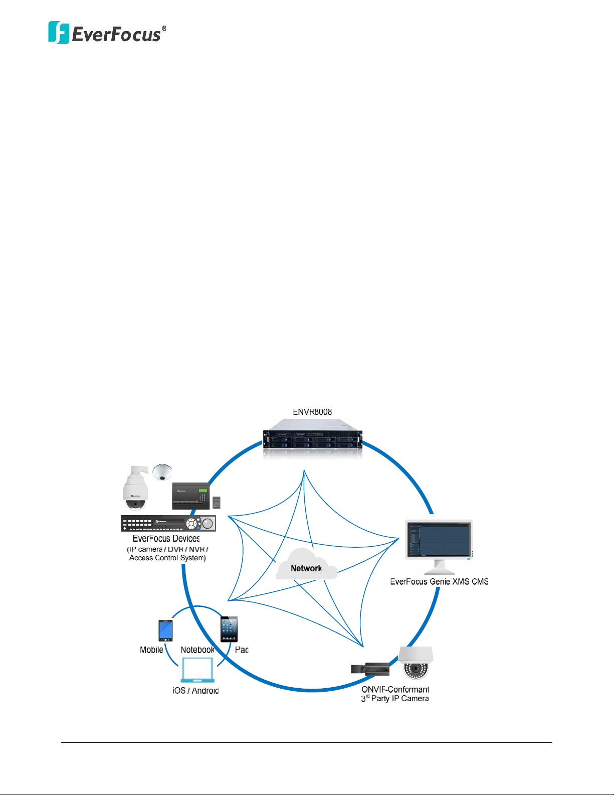
EverFocus NVR8008X is an enterprise-level NVR, supporting scalable channel numbers from 64 up
to 100 channels. Featured with 8-bay hot swappable SATAIII HDDs and RAID 0,1,5,6,10functionality
with the highest data protection, the NVR8008X is able to record at 250 Mbps in speed with
approximately64 channels working simultaneously at 2-megapixel / 30 fps with H.264 codec
without remote playback.
Operating on a Linux-based system, the NVR8008X provides a storage capacity of up to 32 TB (4 TB
per drive),and is compatible with all EverFocus devices such as IP cameras, DVR, NVR, access
control systems and EverFocus CMS software, Genie XMS. The ONVIF -conformant 3rd-party
cameras can also be connected to the NVR. Industry standard video compression formats, such as
H.264, MPEG4 and M-JPEG (depends on IP cameras) are all supported. The NVR8008X is also
supported by EverFocus MobileFocus apps on iOS and Android devices extending video surveillance
from fixed locations to mobile environments.
Chapter
1
Page 8
NVR8008X Enterprise Rack Mount NVR
2
1.1 Supporting Operating Systems and Browsers
Operating System: Microsoft Windows XP (32-bit)/ 7 (32/64-bit)/ 8 (32/64-bit)
Web Browsers: Google Chrome
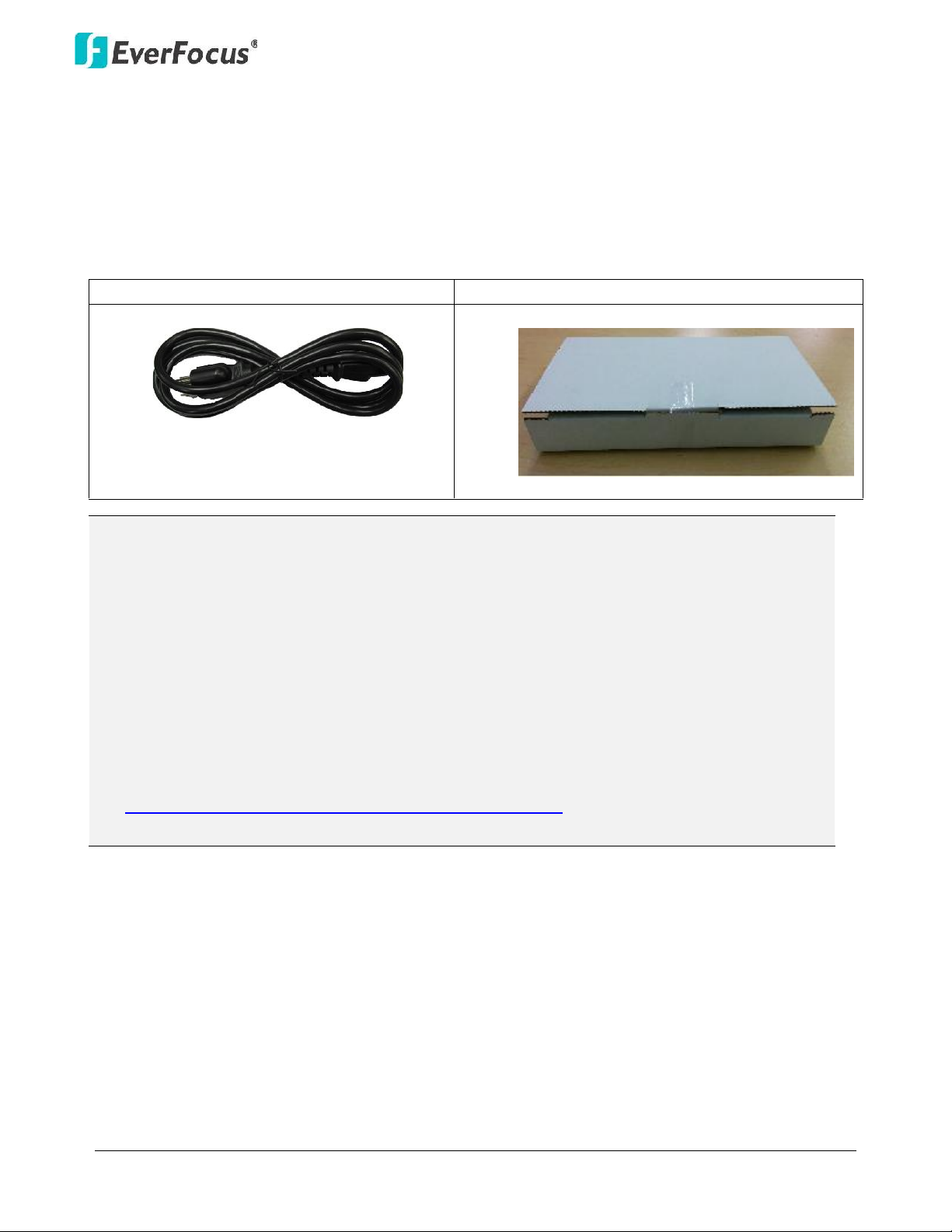
1.2 Packing List
NVR8008X x1
Quick Guide x 1
Power Cord x 1
HDD. Packed in white boxes
Note:
1. Any physical damage to the NVR due to improper installation or handling will not be
covered under warranty.
2. Every install environment is different. RAIL MOUNTS are not included with the NVR. This is
an optional accessory.
3. Equipment configurations and supplied accessories vary by country. Please consult your
local EverFocus office or agents for more information. Please also keep the shipping carton
for possible future use.
4. Contact the shipper if any items appear to have been damaged in the shipping process.
5. The latest version of the manuals is available for download from the EverFocus Website.
This also contains part numbers for optional accessories.
http://www.everfocus.com/product.cfm?productid=1855
Page 9
NVR8008X Enterprise Rack Mount NVR
3
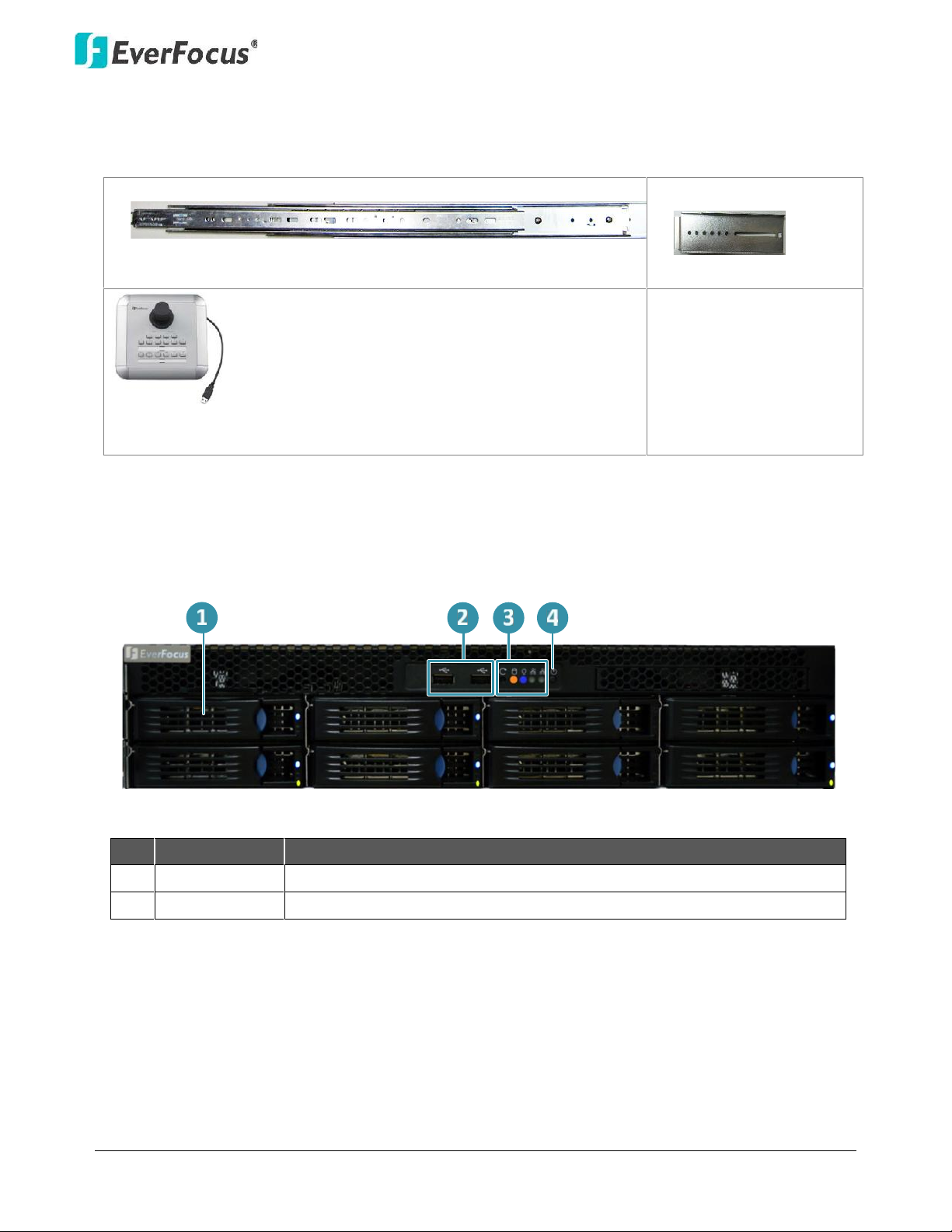
1.3 Optional Accessories
Rack Mount Rail x 2
Front Bracket x 2
EKB200 (USB controller keyboard: connect to the PC to
control the PTZ cameras connected to the NVR
1.4 Front Panel
No.
Name
Description
1
HDD Tray
Pull the HDD tray out to install the HDD.
2
USB
2 USB2.0 ports for connecting to a mouse or external storage device.
Page 10
NVR8008X Enterprise Rack Mount NVR
4
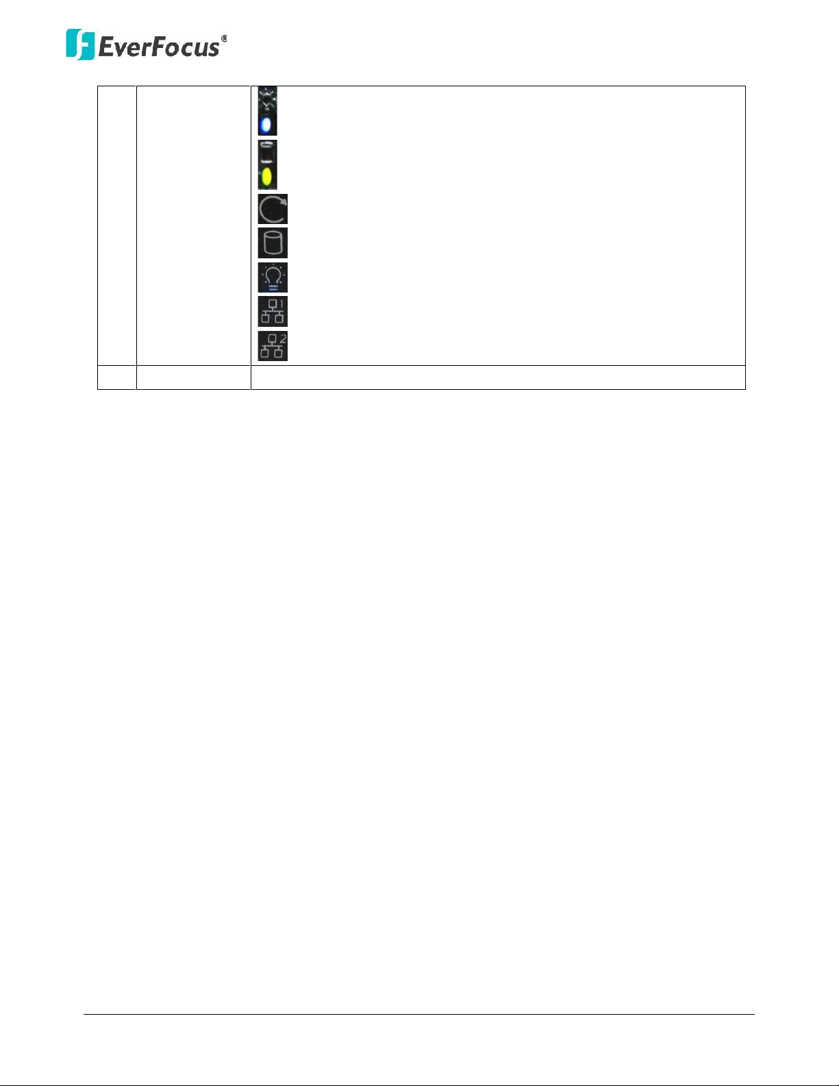
3
Status LED
Power: Indicates the HDDs are installed.
HDD R/W: Indicates the HDDs are reading/writing data.
Reset: Use a paper clip to press the reset button.
HDD: Indicates the internal HDD 1~8 is activating.
Power: Indicates the power is on.
LAN1: Indicates the NVR is connected to the network.
LAN2: Indicates the NVR is connected to the network.
4
Power
Press to turn on / off the NVR.
Page 11
NVR8008X Enterprise Rack Mount NVR
5
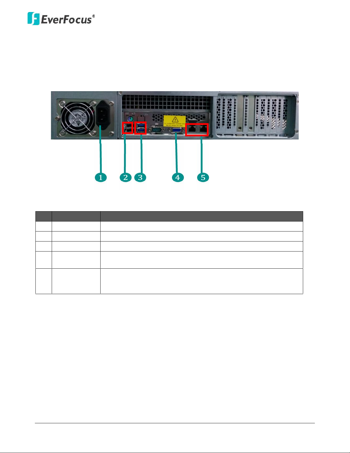
1.5 Rear Panel
No.
Name
Description
1
Power Port
Connects to the 100-240 VAC~ power using the supplied Power Cord.
2
USB2.0 Port
Two USB2.0 ports
3
USB 3.0 Port
Two USB3.0 ports
4
VGA Port
Connects to monitor using a VGA cable. This is for configuration
purpose only, not for live viewing of IP camera.
5
Network
Connects to the network using a standard RJ-45 CAT5 10/100Mb
Ethernet cable. Connects to a router or switch for connecting IP
cameras using a standard RJ-45 CAT5 10/100Mb Ethernet cable.
Page 12
NVR8008X Enterprise Rack Mount NVR
6
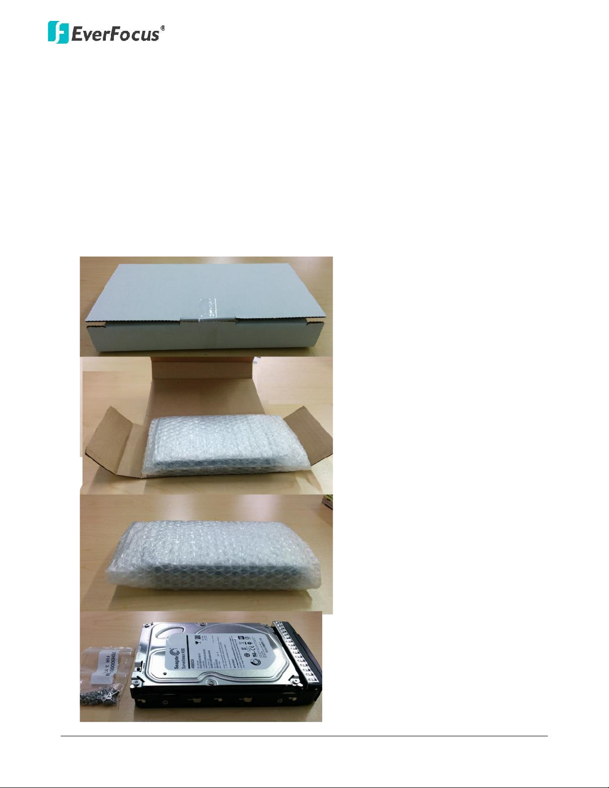
2. Installation
2.1 Hard Disk Drive Installation
1. Open the white boxes containing the hard drive.
Chapter
2
Page 13
NVR8008X Enterprise Rack Mount NVR
7
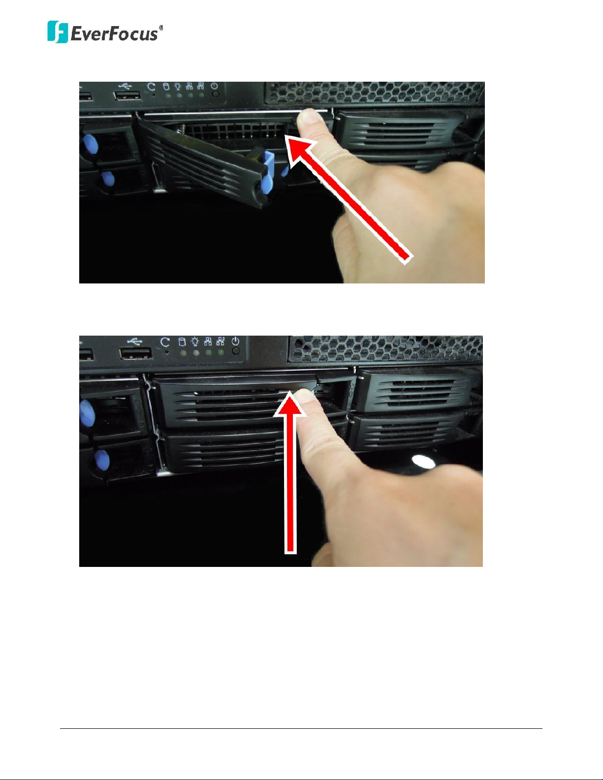
2. Open the HDD tray by pressing the blue button.
3. Insert the HDD tray into the NVR, and push back the black panel to close it.
Page 14
NVR8008X Enterprise Rack Mount NVR
8
2.1.1 Hard Disk Compatibility List
Please use the hard disk models recommended in the list below to ensure your hard disks will be
compatible.
SATA Hard Disk
Model
Capacity
Seagate
CE-Video SATA3 / ST1000VM002
1TB
CE-Video SATA3 / ST2000VM003
2TB
CE-Video SATA3 / ST3000VM002
3TB
CE-Video SATA3 / ST4000VM000
4TB
SV35 SATA6 7200/ ST4000VX000
4TB
SV35 SATA6 7200/ ST1000VX000
1TB
SV35 SATA6 7200/ ST2000VX000
2TB
SV35 SATA6 7200/ ST3000VX000
3TB
Constellation CS SATA3 7200 / ST1000NC000
1TB
Constellation CS SATA3 7200 / ST3000NC000
3TB
CE-Video SATA6 5900RPM / ST1000VM002
1TB
CE-Video SATA6 5900RPM / ST2000VM003
2TB
SV35 SATA3 7200/ST3000VX000
3TB
SV35 SATA3 7200/ST2000VX000
2TB
SV35 SATA3 7200/ST1000VX000
1TB
Toshiba
MD03ACA200V 2TB SATA 7200RPM 64MB
2TB
MD03ACA300V 3TB SATA 7200RPM 64MB
3TB
MD03ACA400V 4TB SATA 7200RPM 6MB
4TB
Western Digital
WD40PURX-64GVNYO
4TB
WD30PURX-64P6ZY0
3TB
WD20PURX-64P6ZY0
2TB
WD10PURX-64D85Y0
1TB
Note: If using two or more hard disks, please choose the hard disks with the same capacity.
Page 15
NVR8008X Enterprise Rack Mount NVR
9
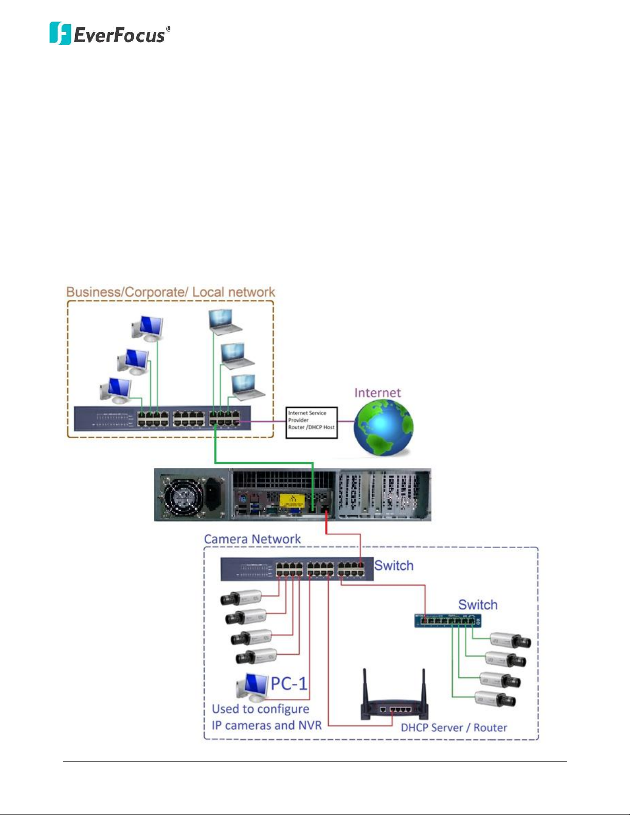
2.2 Basic Connection
The instructions below describe the basic connection for NVR8008X.
Before powering on the NVR, make sure the internal HDDs have been installed
properly. When you have completed the basic cable connections, you are ready to
turn on the NVR.
This NVR has dual network ports. It is recommended to separate your IP-camera network from your
other network.
The diagram below is an example of an initial network set up.
Page 16

NVR8008X Enterprise Rack Mount NVR
10
Once NVR and IP camera configuration is complete, the DHCP Server/Router and
PC-1 can be removed from the Camera Network.
Page 17

NVR8008X Enterprise Rack Mount NVR
11
2.3 Checking the Dynamic IP Address
You can look up the IP address and access the Web interface of the NVR using the IP Utility (IPU)
program, which is contained in the CD. It can also be downloaded from EverFocus’ Website:
http://www.everfocus.com/
1. Save IP Utility Setup AutoRun.exe in your computer. Double click the .exe file and follow
the on
‐screen instructions. Check
Run IPUtility.exe and click the Finish button, the IP Utility
will be launched to search the IP devices connected in the same LAN automatically.
2. To optionally configure the Machine Name, IP Address, IP Type or Port Number using the IPU:
a. Log in the NVR by checking the desired model and then click the Log in icon. The Log in
dialog box appears.
Page 18

NVR8008X Enterprise Rack Mount NVR
12
b. Type the Username and Password. Click the OK button, the status of the selected camera
will display Login.
Note:
1. The default user ID is admin and the default password is 11111111.
2. If you select more than one NVR that have the same user ID / password, you will
be able to log in several NVRs at once.
c. Right click the column to configure the setting. Click Apply Changes button to apply
and save the settings.
Note: Most networks uses DHCP to assign IP address, if you are unsure of your network
settings, please consult your network administrators for configuration details .
3. To access to the Live View window, open a Google Chrome Web browser, type the IP address
of the NVR in the address field and press the Enter key on the keyboard, the Welcome window
appears. Follow the instruction steps to update the latest Plug -in version.
Note: The Welcome window will only be prompted for the first time login in order to
update the system to the latest plug-in version.
Page 19

NVR8008X Enterprise Rack Mount NVR
13
4. After reloading the webpage, the login window is displayed again. Type the user ID and
password to log in. By default, the user ID is admin, and the password is 11111111.
5. Click the Login button, the Live View window (see 3.2 Live View Window) appears.
Page 20

NVR8008X Enterprise Rack Mount NVR
14
3. General Operation
You can view the live videos or operate the Live View Window through the Web browser.
3.1 Login / Logout
1. To log in the system, open a Google Chrome Web browser, type the IP address of the NVR in
the address field and press the Enter key on the keyboard , the Welcome window pops up.
Follow the instruction steps to update the latest Plug -in version. After reloading the webpage,
the login window pops up. Type the user ID and password to log in. By default, the user ID is
admin and the password is 11111111.
Note: The Welcome window will only be prompted for the first time login in order to
update the system to the latest plug-in version.
2. To log out the system, click the Logout button on the upper-right corner of the Live View
Window. The system will return to the login window.
Chapter
3
Page 21

NVR8008X Enterprise Rack Mount NVR
15
3.2 Live View Window
No.
Name
Description
1
List
Click to display the Device List
2
Menu Tree
Click to show / hide the Menu Tree of the Device List.
3
Group
Click to configure the Group settings (see 3.2.3.1 Group
Settings).
4
Ratio
Click to switch live video ratio between original (source video)
and extended (to the layout screen).
5
eMap
Click to display the eMap (see 3.2.1 eMap).
6
OSD Display Mode
Click to show / hide the information of device name and time.
7
Expand / Collapse
Click to expand or collapse the Device List.
8
Full Screen
Click to display the Live View layout in full screen.
9
Option
Click to show/hide the Live View Tool Bar at the bottom of each
cell. See 3.2.2 Live View Tool Bar for more details.
10
Device Detail
Click to enter the Device List setup page (see 3.2.3 Device List
Setup).
11
Live View
Click to display the Live View layout.
Page 22

NVR8008X Enterprise Rack Mount NVR
16
12
Playback
Click to enter the playback page for multi-channel playback.
13
Close Stream
Click to disconnect the live streams.
14
Event List
Click to enter the Event List setup page.
15
Access List
This function is optional. Click to enter the Access Control setup
page.
16
IVS
This function is optional. Click to enter the Intelligent Video
Surveillance (IVS) setup page.
17
Setting
Click to enter the Settings page (see 3.5 Setting).
18
Add
Click to save the current live layout as a Page in the Page List
(see 3.2.5 Page Setting).
19
Logout
Click to log out the system.
20
Theme Switch
Click to switch the theme between the dark and light.
21
Layout Detail
Click to enter the Layout Design page. You can further create or
modify the personal layout design (see 3.2.4 Layout Setting).
22
Layout
Click to enter the layout page for layout selection (see 3.2.4
Layout Setting).
23
PTZ Detail
Click to enter the PTZ setup page.
24
PTZ Control
Click to display the PTZ Control panel.
25
Page Detail
Click to enter the Page setup page (see 3.2.5 Page Setting).
26
Page
Click to display the Page List (see 3.2.5 Page Setting).
27
Time Search
Click to display the Time Search calendar for playback.
28
Digital Zoom / Fisheye
Click to enter the Digital Zoom / Fisheye operation page.
Page 23

NVR8008X Enterprise Rack Mount NVR
17
3.2.1 eMap
On the Live View Window, click the eMap button, the eMap page appears.
1 2 3 4 5
No.
Name
Description
1
List
Click to display the eMap list.
2
Select
Click to select an eMap picture (PNG, JPG, JPEG, GIF, TIFF).
3
Delete
Click to delete an eMap.
4
Save
Click to save the settings.
5
Clear
Click to clear the eMap settings.
Page 24

NVR8008X Enterprise Rack Mount NVR
18
3.2.2 Live View Tool Bar
You can use the Live View Tool Bar to control the main / sub streams, local recording, audio,
snapshot and playback of the IP camera. On the Live View Window, click the Option button, the Live
View Tool Bar appears on the top of the live view cell.
No.
Name
Description
1
Stream Type
Click to switch between main and sub stream.
2
Record
Click to start / stop local recording. You have to set up the recording
path for the recordings in advance (see 3.3.1 Setting up the
Recording Path).
3
Audio (Speaker)
Click to transfer the sound from the device to the client side (remote
client PC) if the speakers have been connected to the device. Note
that a (built-in) amplifier and external power supply are required for
the speakers.
4
Snapshot
Click to take a snapshot. You have to set up the recording path for
the snapshots in advance (see 3.3.1 Setting up the Recording Path).
5
Microphone
Click to transfer the sound from the client side (remote client PC) to
the device if the microphones have been connected to the client
side. Note that a (built-in) amplifier and external power supply are
required for the microphones.
6
Quick Playback
Click to display the Quick Playback Bar for playing back (see 3.4
Quick Playback).
7
Close
Click to disconnect the stream.
Page 25

NVR8008X Enterprise Rack Mount NVR
19
3.2.3 Device List Setup
You can configure and manage the device list using this page. On the Live View Window, click the
Device Detail button, the Device List Setup page appears on the right window.
No.
Name
Description
1
Device Detail
Click to enter the Device List setup page.
2
Device
Click to display the Device List.
3
Group / List
Click to switch between Group view and List view for the Device
List. You can also setup the Group settings (see 3.2.3.1 Group
Settings).
4
Edit / View
Click to switch between Edit and View mode for the Device List.
For editing the added devices, see 3.2.3.2 Editing Device
Configurations.
5
Export
Click to export the Device List file (.csv).
6
Load Template
Click to download the Device List Template (.csv).
7
Total
Display the current number of the connected devices.
8
Device Type List
Click the drop down list and select the desired device type (see
3.2.3.3 Device Type List).
9
Import
Click to import the Device List file (.csv).
10
Delete
Select the desired devices and click the Delete button to remove
the devices from the Device List.
11
Add
Click to enter the Maintain page for adding devices. For more
details on adding devices, see 3.2.3.4 Adding Devices.
12
Device Indicator
The Device Indicator indicates the status of the devices (see
3.2.3.5 Device Indicator).
Page 26

NVR8008X Enterprise Rack Mount NVR
20
3.2.3.1 Group Settings
You can configure the group settings on this page.
1. On the Device List setup page, click the Group button, and then click the Group folder on the
Group List, the modification icons appears.
2. Click the add node button and enter a name to add a node.
3. Drag a device from the Device List and drop it to the created group. You can drag multiple
devices to a single group.
Page 27

NVR8008X Enterprise Rack Mount NVR
21
4. Click the Save button to save the settings.
3.2.3.2 Editing Device Configurations
To edit the added devices, on the Device List Setup page, click the Edit icon, click the column
you want to configure and input the setting. Click the Update button to save the settings.
3.2.3.3 Device Type List
You can add devices, image, message or even a Website to the system . On the Device List Setup
page, click the Device Type List drop-down list to select a device type.
No.
Name
Description
1
IPCAM
IP camera.
2
DVR
EverFocus DVR.
3
NVR
EverFocus NVR.
4
Message
Display message for Text or Marquee mode.
5
RTSP
RTSP streaming URL.
6
Image
Picture (PNG, JPG, JPEG, GIF, TIFF).
7
Access
Access controller or reader.
8
Access Server
ENS200 Access management server.
9
XMS
EverFocus XMS server.
10
WEB
Web URL.
Page 28

NVR8008X Enterprise Rack Mount NVR
22
3.2.3.4 Adding Devices
You can manually or automatically add devices to the NVR. On the Device List Setup page, click the
Add button, the Maintain page appears.
Manually Adding a Device
Select a device type from the Device Type drop-down list, enter the device information and click
the Save button to save the settings. The device will be added to the Device List.
Automatically Adding Devices
On Figure above, click the Auto Detection icon to switch to the Auto Detection page.
1. Check the square beside the Device Name to select a desired device. (Note: If multiple devices
have the same ID and Password, you can select multipl e devices on this step).
Page 29

NVR8008X Enterprise Rack Mount NVR
23
2. Type the device ID and Password in the above columns.
3. Click the Apply to Select icon to apply the input ID and Password to the selected devices.
4. Click the Authentication icon, the verified devices will be marked with a check mark.
5. Click the Save button, the device will be listed on the Device List.
3.2.3.5 Device Indicator
The Device Indicator indicates the status of the devices.
Status
Description
Connected
Indicates the devices have been connected with streaming
displayed.
Recording
Indicates the live view recording (schedule record) is on.
Event Triggered
Indicates an event occurs or an alarm is triggered.
No Connection
Indicates there is no connection of this device.
Disconnect
Indicates the devices have been disconnected.
Page 30

NVR8008X Enterprise Rack Mount NVR
24
3.2.4 Layout Setting
You can configure the layout on this page. On the Live View Window, click Layout from the left-side
bar, select a layout by clicking on the desired layout, the selected layout should be appeared on the
right-side window.
To add the devices to the layout cells, on the left-side bar, click Device, drag and drop the devices
from the Device List to the layout cells.
To create personalized layout, on the left-side bar, click the Layout Detail button, select an
editable layout and click the Add button, an edit bar should appear on the top of the window. Use
the function buttons to add/delete/merge/separate layout cells. Click the Save icon to save the
settings.
Page 31

NVR8008X Enterprise Rack Mount NVR
25
3.2.5 Page Setting
You can create multiple live view layouts and then save them as pages. Create a layout and then
click the Add icon on the Live View Window. The layout will be saved in the Page List as a page.
To modified pages, on the Live View Window, click the Page Detail button on the left-side bar and
then click the Update button.
Page 32

NVR8008X Enterprise Rack Mount NVR
26
3.3 Recording
You can set up a weekly recording schedule for the connected devices to record the videos in your
computer. The recordings will be saved in AVI files. You have to set up a recording path for the
recordings before activating this function (see 3.3.1 Setting up the Recording Path).
On the Live View Window, click the Setting button, click the Record & Play menu bar on the left,
click Schedule, and the following Schedule page appears.
Recording Type buttons:
: Continuous recordings only.
: Event recordings only.
: Continuous and Event recordings.
Note: For Event recordings, you have to configure the event settings in advance. On the Live
View Window, click the Setting button and then click Event on the menu bar to enter the Event
Setting page. For motion detection setting, please refer to 3.5.7 Motion Detect.
To add a recording schedule to the Schedule Name List:
1. Select a recording type by clicking on the Recording Type buttons.
2. Move the cursor on a desired time square, click and drag the cursor to set up the time period
on each day. The squares will be displayed in blue/yellow/green to indicate which recording
type has been applied to the time period.
3. Click the Add button and enter a name for the recording schedule.
4. The recording schedule should be listed in the Schedule Name List.
Page 33

NVR8008X Enterprise Rack Mount NVR
27
To apply a recording schedule to the desired devices:
1. Click the Device List button, select the desired devices and then click the Save button.
2. Select a desired recording schedule from the Schedule Name List drop-down list and then click
the Apply button.
3.3.1 Setting up the Recording Path
On the Live View Window, click the Setting button, click the User Setting menu bar on the left, click
Local Save Settings, and the following page appears. Click the Select button in the Save Recording
in field to select a path for the recordings. Click the Apply button to save the settings. You can also
set up a path for the snapshot images in the Save Snapshot in field.
Page 34

NVR8008X Enterprise Rack Mount NVR
28
3.4 Quick Playback
You can play back the Live View recordings of the cameras stored in the client computer using the
internal built-in player. On the Live View Window, click the Option button, the Live View Tool Bar
appears on the top of the live view cell. Click the Quick Playback button, the playback bar appears
on the button of the window. You can control the playback bar on this page.
The Quick Playback function is designed to play back the recordings start from the pre-configured
time. Before using the Quick Playback function, you have to configure the Playback settings in
advance. On the Live View Window, click the Setting button, click Record & Play from the menu bar
and click Playback, the Playback setup page appears. Enter the desired time for playing back the
recording. Take the below image for example, if the current system clock time is 17:35:00, the start
time for the playback recording will start from 17:34:00 (60 seconds ago from 17:35:00).
Page 35

NVR8008X Enterprise Rack Mount NVR
29
3.5 Setting
You can configure the system settings on this page. On the Live View Window, click the Setting
button, a menu bar appears on the left side of the window. Enter each field to configure the
settings.
Page 36

NVR8008X Enterprise Rack Mount NVR
30
3.5.1 Date / Time
On the left-side menu bar, click System Setting and then click Date/Time. Enter the current date
and time, and then click the Apply button to save the settings.
3.5.2 License
On the left-side menu bar, click System Setting and then click License. Enter the data, and then click
the Activate button to activate the license.
Page 37

NVR8008X Enterprise Rack Mount NVR
31
3.5.3 User Management
You can create multiple user accounts with different privileges using this page. On the left-side
menu bar, click User and then click User Management. Click Change Mode, click the Add button to
add a user, input the password for the user, and select a user group from the drop-down list and
then input the email address of the user. Click the Save button, the user should be listed in the User
Management list.
Note that there are three group types for the user account: Administrator, Operator and Viewer.
Each group type is applied with the fixed privileges as listed below.
Page 38

NVR8008X Enterprise Rack Mount NVR
32
3.5.4 Recording Data Report
This Recording Data Report shows the recording status of all the devices. On the left-side menu bar,
click System Information and then click Recording Data Report. Click to select a Date and Time,
click Related Device List to select devices, and click Query to display the recording status report.
You can click By Minutes/ Second or By Hour to show the report in different timeline formats.
: A yellow block represents only events are recorded during this time block.
: A green block represents the continuous and event recording during this time
block.
: A blue block indicates the continuous recording during this time block.
: A red block may result from disconnection, power-loss or ongoing recording during
this time block.
Page 39

NVR8008X Enterprise Rack Mount NVR
33
3.5.5 Disk Information
This Disk Information will automatically show the detailed information of all the installed hard disk
drives, such as model name, disk type and capacity. On the left -side menu bar, click Storage Device
and then click Disk Information.
3.5.6 Storage Device Management
You can manage all the storage devices on this page. On the left-side menu bar, click Storage
Device and then click Storage Device Management. Click Format to format the HDD for the first
time. (WARNING: This will effectively ERASE the ENTIRE hard disk! ) Click Add to add a new group,
enter a group name, and then drag and drop the disks from the Unused Group to the newly created
group. Click Apply to group the disks.
Note that one disk can only be added to one group.
Page 40

NVR8008X Enterprise Rack Mount NVR
34
You can also configure the detailed settings for each group.
Auto Erase Recording / Day(s): The hard disk will automatically erase video after it has been on the
hard drive for the entered number of days.
Overwrite: Check the box to overwrite the hard disk when the capacity is used up to 99% (the
capacity does not include the locked space of the disk).
Lock %: Enter a percentage for a write protected segment of the hard disk (will not be overwritten).
However, this locked space is currently reserved.
For example, if you check the Overwrite box and you set 20% of the locked disk space, when the
disk is used up to 99% of the remaining 80% unlocked space, it will start overwrite the disk.
To save the IP camera recording to this disk group, please see below:
1. Go to the Live View page by clicking the Live View button, and then click Device
Detail.
Page 41

NVR8008X Enterprise Rack Mount NVR
35
2. Double-click a device to display the device setting, and then click Storage Device to select a
desired disk group.
3. Click the Save button on the upper-right corner of the page.
Page 42

NVR8008X Enterprise Rack Mount NVR
36
3.5.7 Motion Detection
You can set up the motion detection of the IP camera on this page. On the left-side menu bar, click
Event and then click Motion Detect. Check the Enable box on the devices which you want to set up
the motion detection setting, and then click Edit Motion Grid to bring up the motion setting page.
On the left side, click on a device or select multiple devices and its image will be displayed at the
right side. Click and drag a rectangle on the image to set up a motion area, and the selected area
will be highlighted in blue. You can only set up one motion area. Click Apply to save the setting.
Page 43

NVR8008X Enterprise Rack Mount NVR
37
4. Specifications
Commander II
Series
ENVR-8008
Removable HDD
Trays
8xSATA
Server Operating
System
Linux
Client Operating
System
Windows XP (32-bit) / Win7 (32 and 64-bit) / Mac OS X v10.6
Number of Cams per Recording
Serve
64*
Maximum Number of Cams per
Monitor
128
Maximum Number of Cams per
Software
400
ONVIF Device
Support
Yes
Video
Compression
H.264, MJPEG
Multiple Stream
Profile
Yes
Automatic Camera Model
Detection
Yes
Edge
Motion
Yes
Intuitive
E-map
Yes
I/O
Control
Yes
Audio Recording
(Listen)
Yes
PTZ
control
Yes
Support Panorama PTZ
(360°)
Yes
Record on
Schedule
Yes
Record on
Event
Yes
Tim e Search and
Playback
Yes
Central User
Privilege
Yes
Web
Client
Internet Explorer 9 and later, Firefox 4.0-9.0
,Chrome(Windows version)
Mobile
Client
iPhone, iPad, Android
Auto/Manual
Backup
Yes
Export
AVI
Live
Viewing
16 CH
Dual
LAN
Yes
Chapter
4
Page 44

NVR8008X Enterprise Rack Mount NVR
38
RAID
0,1,5,6, 10
Watchdog
Yes
Instant Live View/
Playback
Yes
System
Automatic Device
Scanning
Yes
Automatic Device Model
Detection
Yes
Log
Tool
Yes
License
Management
Yes
PTZ
Point and click control (by
camera)
Yes
Go to Preset
Positions
Yes
Digital
PTZ
Yes
Support Panorama PTZ
(360°)
Yes
Joystick
support
Yes
Live View
Public/Private
View
Yes
Max Content Per
View
128
Hide
Toolbar
Yes
View
Tour
Yes
Snapshot
Yes
Instant
Playback
Yes
Recording &
Backup
Manual
Record
Yes
Always
Record
Yes
Schedule
Record
Yes
Record on
Event
Yes
Recording to Storage
Area
Networks(SAN:
iSCSI)**
Yes
Recording to NAS
(iSCSI)**
Yes
Pre-event and Post-event
Recording
Yes
Playback
Max View Items Per
View
128
Event list in
Recording
Yes
Event Associated
Video
Yes
Graphical
Timeline
Yes
Adjust Playback
Speed
Yes
Motion/Event
Search
Yes
Time/Date
Search
Yes
Event
Digital
Input
Yes
Page 45

NVR8008X Enterprise Rack Mount NVR
39
Edge Motion
Detection
Yes
Camera Signal
Lost
Yes
Abnormal disk
status
Yes
Event
Notification
Camera
Recording
Yes
Trigger Digital
Output
Yes
Send
E-mail
Yes
On Screen
Display
Yes
Popup Live
Video
Yes
User
Privilege
Restrict Access to Live
View
Yes
Restrict Access to
Playback
Yes
Restrict Access to
PTZ
Yes
Configuration
Privilege
Yes
Others
Supported
Language
English, Japanese, Traditional Chinese, Spanish, Deutsch,
French, Russian, Portuguese (Brazil),Dutch, Simplified Chinese
Korean, Polish, Portuguese (Brazil), Russian, Serbian, Spanish,
Swedish
Hardware
Specifications
Number of
Drives
8xSATA
Max Storage Per
Drive
4TB
RAID
Level
RAID 0, 1, 5, 6, 10
I/O
Interface
4xUSB 2.0 ; 2xUSB 3.0
1xeSATA (for DAS)
LAN Transmission
Speed
2x 10/100/1000 Mbps (RJ45x2)
Voltage
100-240V
Power
Consumption
500W *1
Device Dimension
(H x W x D)
88 x 430 x 660 mm
Device Weight (Without
Drive)
8.8 kg (16.75lbs)
Temperature
Operating: 0°C-40°C
Humidity
Operating: 5%-95%
Page 46

NVR8008X Enterprise Rack Mount NVR
40
Remote Client System Minimum
Requirement
OS
Windows XP (32-bit) / Win7 (32 and 64-bit)
CPU
Intel Core 2 Duo, 2.6GHz
RAM
4GB
LAN Transmission
Speed
10/100/1000 Mbps (RJ45)
Web Client
Internet Explorer 9 and later, Firefox 4.0-9.0, Chrome
(Windows version)
Mobile
Device
iPhone, iPad, Android
Page 47

EverFocus Electronics Corp.
EverFocus Taiwan:
12F-1, No.79, Sec. 1, Shin-Tai Wu Road,
Hsi-Chih, New Taipei City, Taiwan
TEL: +886 2 2698 2334
FAX: +886 2 2698 3943
www.everfocus.com.tw
marketing@everfocus.com.tw
EverFocus Europe - Germany:
Albert-Einstein-Strasse 1, D-46446
Emmerich, Germany
TEL: +49 2822 93940
FAX: +49 2822 939495
www.everfocus.de
sales@everfocus.de
EverFocus China - Beijing:
Room 609, TechnologyTradeBuilding,
Shangdi Information Industry Base,
Haidian District, Beijing 100085, China
TEL: +86 10 6297 3336~39
FAX: +86 10 6297 1423
www.everfocus.com.cn
marketing@everfocus.com.cn
EverFocus China - Shenzhen:
4F, No. 2, D4 Building, Wan Yelong
Industrial Park, Tangtou Road, Shiyan,
Baoan, Shenzhen, Guangdong 518101, China
TEL: +86 755 2765 1313
FAX: +86 755 2765 0337
www.everfocus.com.cn
marketing@everfocus.com.cn
EverFocus USA - California:
1801 Highland Avenue, Unit A, Duarte, CA91010, USA
TEL: +1 626 844 8888
FAX: +1 626 844 8838
www.everfocus.com
sales@everfocus.com
EverFocus USA - New York:
415 Oser Avenue, Unit S, Hauppauge, NY11788, USA
TEL: +1 631 436 5070
FAX: +1 631 436 5027
www.everfocus.com
sales@everfocus.com
EverFocus Japan:
3F, Kuramochi, Building II, 2-2-3
Koto-Bashi,Sumida-Ku, Tokyo, 130-0022, Japan
TEL: +81 3 5625 8188
FAX: +81 3 5625 8189
www.everfocus.co.jp
info@everfocus.co.jp
EverFocus India:
UBS, 629/1243, 1st Floor, G Block, Behind Teacher’s
Colony,Bandra Kurla Complex, Bandra (E),
Mumbai 400 051, India
TEL: +91 22 67264500
FAX: +91 22 67264518
www.everfocus.in
sales@everfocus.in
EverFocus China - Shanghai:
Room 403, Ruijin Business Center, No.96,
Zhaojiabang Road, Luwan district, Shanghai 200020,
China
TEL: +86 21 6471 2229 / 6471 2291
FAX: +86 21 6471 0566
www.everfocus.com.cn
marketing@everfocus.com.cn
Your EverFocus product is designed and
manufactured with high quality materials
and components which can be recycled
and reused.
This symbol means that electrical and
electronic equipment, at their end-of-life,
should be disposed ofseparately from
your household waste.
Please, dispose of this equipment at your
local community waste
collection/recycling centre.
In the European Union there are
separate collection systems for used
electrical and electronic product.
Please, help us to conserve the
environment we live in!
Ihr EverFocus Produkt wurde entwickelt
und hergestellt mit qualitativ
hochwertigen Materialien und
Komponenten, die recycelt und wieder
verwendet werden können.
Dieses Symbol bedeutet, dass elektrische
und elektronische Geräte am Ende ihrer
Nutzungsdauer vom Hausmüll getrennt
entsorgt werden sollen.
Bitte entsorgen Sie dieses Gerät bei Ihrer
örtlichen kommunalen Sammelstelle oder
im Recycling Centre.
Helfen Sie uns bitte, die Umwelt zu
erhalten, in der wir leben!
P/N: 4605PNRP18B013A Ver.A
 Loading...