

Page 1
User Manual
NVR
User Manual
Ver. 1.1.0.111026.00
Page 2

1
Table of Contents
1. Installation ................................................................... 8
1.1 Installation Process ..................................................... 8
1.2 LED Status Definitions ............................................... 16
2. Settings ..................................................................... 17
2.1 Camera Setup ........................................................... 17
2.1.1 Add Cameras by Camera Search........................ 17
2.1.2 Add Cameras Manually ..................................... 19
2.1.3 Modify Camera Information .............................. 20
2.1.4 Modify Camera Parameters ............................... 20
2.1.5 Set up Lens Settings ........................................ 21
2.1.6 Set up 2nd Stream .......................................... 22
2.1.7 View Camera Status ........................................ 22
2.2 Recording & Event Setup ............................................ 23
2.2.1 Recording Mode Setup ..................................... 23
2.2.2 Recording Schedule / Event Setup ..................... 24
2.2.3 Camera Events and Responding Actions Setup .... 27
2.2.4 I/O Box Input and Responding Action Setup........ 29
2.2.5 System Events and Responding Actions Setup ..... 30
2.2.6 SMTP Server Setup .......................................... 32
2.2.7 Add Event Contacts ......................................... 33
2.3 RAID & File Settings .................................................. 33
2.3.1 Create a RAID Volume ..................................... 33
2.3.2 View RAID Volume Status ................................. 35
2.3.3 View Disk Drive Information ............................. 36
2.3.4 Modify RAID Volume ........................................ 36
2.3.5 Delete a RAID Volume ...................................... 39
2.3.6 Format ........................................................... 40
2.3.7 Modify the “My Network Places” Protocol Settings 40
2.3.8 Modify the FTP Protocol Settings........................ 41
2.4 Auto Backup ............................................................. 42
2.4.1 Set up Backup Schedule ................................... 42
2.4.2 Set up Backup Server ...................................... 43
2.5 Network Setup .......................................................... 44
2.5.1 View Network Status ........................................ 44
2.5.2 Network Settings ............................................. 44
2.5.3 Auto Port-Forwarding ....................................... 46
Page 3

2
2.5.4 Network Service Setup ..................................... 48
2.5.5 CMS Service Setup .......................................... 49
2.6 Management ............................................................. 49
2.6.1 View the List of Users ...................................... 49
2.6.2 Create New Users ............................................ 50
2.6.3 Modify User Information ................................... 51
2.6.4 Change a User’s Password ................................ 51
2.6.5 Delete Users ................................................... 52
2.6.6 Online License Activation .................................. 52
2.6.7 Offline License Activation .................................. 53
2.6.8 View the Event Log .......................................... 55
2.6.9 Save Unit Configuration .................................... 56
2.6.10 Load Unit Configuration / Default Settings ....... 57
2.7 System .................................................................... 58
2.7.1 View System Information ................................. 58
2.7.2 Smart Fan Control ........................................... 59
2.7.3 Buzzer Configuration ........................................ 59
2.7.4 UPS Setup ...................................................... 59
2.7.5 Upgrade the System ........................................ 60
2.7.6 System Date and Time Setup ............................ 61
2.7.7 Daylight Saving Time Setup .............................. 61
2.7.8 Restart the Unit ............................................... 62
2.7.9 Shut Down the Unit ......................................... 62
3. POS ........................................................................... 64
3.1 Introduction ............................................................. 64
3.1.1 System Introduction ........................................ 64
3.1.2 Hardware Installation – SCB-C31A ..................... 65
3.1.3 Software Installation – SCB-C31A ...................... 66
3.1.4 Connection via TCP Client ................................. 67
3.2 Software Setup ......................................................... 68
3.2.1 Activate POS License ........................................ 68
3.2.2 NVR POS Setting ............................................. 68
3.2.3 Insert POS Setting ........................................... 69
3.2.4 Delete POS Device ........................................... 71
3.2.5 Configure POS Setting ...................................... 71
3.3 Tag Filter .................................................................. 71
3.3.1 Add New Tag Filter ........................................... 71
3.3.2 Edit Tag Filter .................................................. 74
Page 4

3
3.3.3 Delete Tag Filter .............................................. 74
3.3.4 Import/Export Tag Filter ................................... 75
3.4 POS Display Font ....................................................... 75
3.4.1 Live View ........................................................ 75
3.4.2 Remote Live Viewer ......................................... 76
3.4.3 Playback......................................................... 77
3.4.4 Playback System ............................................. 78
3.5 POS Transaction Data Search ...................................... 79
3.5.1 Search POS Transaction Data through Playback ... 79
3.5.2 Search POS Transaction Data through Playback
System 80
3.6 Playback Video with POS Data..................................... 80
3.6.1 Select Period by POS Search ............................. 81
3.6.2 Select Period by Data & Time through Playback ... 81
3.6.3 Select Period by Data & Time through Playback
System 81
3.7 Backup Video with POS Data ....................................... 82
3.7.1 Backup through Internet Explorer ...................... 82
3.7.2 Backup through Playback System ...................... 83
3.7.3 Backup through Backup System ........................ 83
4. I/O ............................................................................ 84
4.1 Introduction ............................................................. 84
4.1.1 System Introduction ........................................ 84
4.1.2 HW Installation ............................................... 84
4.1.3 Software Installation – SCB-C31........................ 85
4.1.4 Software Installation – SCB-C24/26/28 .............. 86
4.2 Software Setup ......................................................... 88
4.2.1 Add I/O Box .................................................... 88
4.2.2 Modify I/O Box Information .............................. 89
4.2.3 I/O Pin Setting ................................................ 89
4.3 Relative Configuration and Application ......................... 90
4.3.1 Record on Input Trigger .................................... 90
4.3.2 Input and Responding Actions ........................... 90
4.3.3 I/O Control Panel in Live View ........................... 90
5. Live view .................................................................... 91
5.1 Internet Explorer ....................................................... 91
5.1.1 Live View Control Panel .................................... 91
5.1.2 Live View Setting ............................................. 94
Page 5

4
5.1.3 General Setting ............................................... 94
5.1.4 Stream Profile Setting ...................................... 95
5.1.5 OSD (On-screen display) Setting ....................... 96
5.1.6 Monitor Display Setting .................................... 96
5.1.7 Notification ..................................................... 97
5.1.8 Set up Joystick Control ..................................... 98
5.1.9 Set up Live View Sound on Event ...................... 99
5.2 Remote Live Viewer Application ................................. 100
5.2.1 Remote Live Viewer Application Control Panel ... 100
5.2.2 Unit Connection Setting .................................. 103
5.2.3 General Setting ............................................. 104
5.2.4 Camera Group Setting.................................... 106
5.2.5 Delete/ Rename Camera Groups ...................... 106
5.2.6 Stream Profile Setting .................................... 107
5.2.7 OSD (On-screen display) Setting ..................... 107
5.2.8 Monitor Display Setting .................................. 108
5.2.9 Notification ................................................... 109
5.2.10 Set up Joystick Control ............................... 110
5.2.11 Set up Live View Sound on Event ................. 111
5.2.12 Set up Remote Live Viewer .......................... 111
6. E-Map ...................................................................... 112
6.1 Internet Explorer ..................................................... 112
6.1.1 E-Map Control Panel ...................................... 112
6.1.2 Add Map ....................................................... 113
6.1.3 Edit Map ....................................................... 114
6.1.4 Delete Map ................................................... 114
6.1.5 Add/Rotate Device Indicator ........................... 114
6.1.6 Delete Device Indicator .................................. 114
6.1.7 Layout Adjustment ........................................ 115
6.1.8 Relative Configuration and Application .............. 115
6.2 Remote Live Viewer Application ................................. 116
6.2.1 E-Map Control Panel ...................................... 116
7. Playback .................................................................. 117
7.1 Internet Explorer ..................................................... 117
7.1.1 Playback Control Panel ................................... 117
7.1.2 Search the Recorded Video ............................. 119
7.1.3 Play the Recorded Video ................................. 120
7.1.4 Intelligent Search .......................................... 120
Page 6

5
7.1.5 Recorded Video Enhancement ......................... 122
7.1.6 Save a Video ................................................. 123
7.1.7 Save an Image .............................................. 124
7.1.8 Print an Image .............................................. 124
7.1.9 Backup the Recorded Video ............................ 125
7.2 Remote Playback System Application ......................... 126
7.2.1 Playback System Application Control Panel ....... 126
7.2.2 Set up Unit Connections ................................. 127
7.2.3 Search the Recorded Video ............................. 128
7.2.4 Play the Recorded Video ................................. 129
7.2.5 Intelligent Search .......................................... 129
7.2.6 Recorded Video Enhancement ......................... 130
7.2.7 Save a Video ................................................. 131
7.2.8 Save an Image .............................................. 132
7.2.9 Print an Image .............................................. 132
7.2.10 Backup the Recorded Video ......................... 133
8. Backup and Delete Records ........................................ 134
8.1 The Backup System Application ................................. 134
8.2 Backup the Recorded Video through Windows Explorer 136
8.3 Backup the Recorded Video through FTP .................... 137
8.4 Playback the Backup Records .................................... 137
8.4.1 With Playback Application ............................... 137
8.4.2 Without Playback Application .......................... 137
8.5 Delete the Recorded Video........................................ 137
8.5.1 With Backup Application ................................. 137
8.5.2 Without Backup Application ............................ 140
9. Verification Tool......................................................... 141
9.1 Execute Verification Tool ........................................... 141
9.2 Verify Image / Video ................................................ 142
10. Log out .................................................................... 143
11. Remote PC System Requirements ................................ 144
12. Troubleshooting ........................................................ 145
12.1 Replace a Failed Disk Drive .................................... 145
12.2 Respond to a Critical RAID Volume ......................... 145
12.3 Respond to a File System Error RAID Volume........... 145
12.4 Restore the Default Administrator’s Password .......... 145
12.5 Restore All Default Configuration ............................ 146
12.6 Install ActiveX ..................................................... 146
Page 7

6
12.7 Cannot Log in to the Unit with Internet Explorer ...... 147
Appendix – RAID System....................................................... 148
Introduction to RAID ....................................................... 148
RAID 0 – Stripe .............................................................. 148
RAID 1 – Mirror .............................................................. 149
RAID 5 – Block Striping with Distributed Parity ................... 150
RAID 10 – Mirror / Stripe ................................................. 150
Choosing a RAID Level .................................................... 151
Appendix – Camera Integration .............................................. 153
Camera Search Tool ........................................................ 153
Stream Profile ................................................................ 153
Page 8

7
GNU General Public License
This product includes copyrighted third-party software licensed under the terms of the GNU
General Public License. Please see the GNU General Public License (GPL) for the exact terms and
conditions of this license at www.gnu.org.
Subject to GPL, you may re-use, re-distribute and modify the GPL source code.
Note that with respect solely to the GPL Software, no warranty is provided. We do not offer direct
support for the distribution.
Page 9
8
1. Installation
The electronic components within the unit can be damaged by Electrostatic Discharge
(ESD). Please take precautions at all times when handling the unit or its
sub-assemblies.
To configure the unit, you must install the software onto a desktop/ laptop running
Windows XP-SP3 32bit, Windows 7 32/64bit.
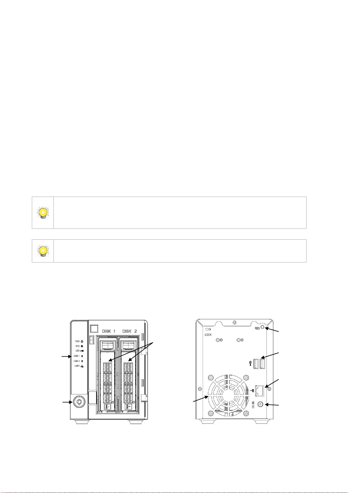
LED
Power Status
System Status
USB Status
DISK 1 Status
DISK 2 Status
Ethernet Activity
Lock
HDD Tray
Cooling Fan
Reset
USB Connection
RJ45 Network
Connection
Power Connection
1.1 Installation Process
Step 1: Unpack the Unit
This package contains the following items:
The unit
Quick Start Guide
Screws for disk drives
Key
Power cord
19V DC power transformer
CD with Install Wizard, Backup, Live View, Playback, Verification
Tool and Offline Tool application, user manual, and quick start guide
2-bay unit front/rear view
Page 10
9
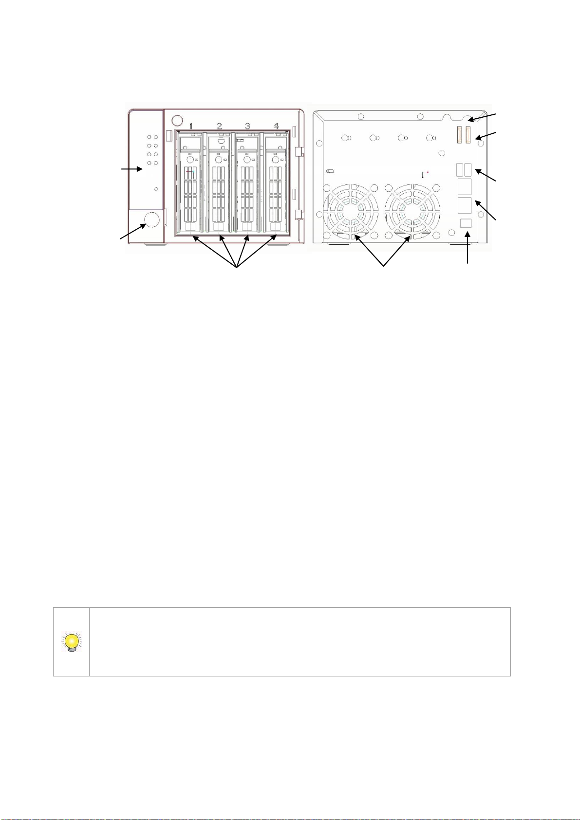
4-bay unit front/rear view
If there are multiple networks at your facility, note the network to which you connect
the unit. You will need this information during the setup process. Please also enable
the DHCP function within the network, as the unit will retrieve an IP address
through DHCP by default.
LED
System Status ; eSATA Status
Ethernet 1 & 2 Activity
DISK 1 & 2 Status
DISK 3 & 4 Status
Power Status
Lock
HDD Trays
Cooling Fan
Power Connection
Reset
eSATA Conn.
1& 2
USB Conn.
RJ45 Network
Conn. 1 & 2
Step 2: Install Hard Drives
Refer to compatibility list and install the HDDs. For optimal performance,
install disks with the same model and storage capacity. The available RAID
level depends on the amount of disks installed.
1. Open the lid on the front of the unit enclosure.
2. Pull an HDD tray from the enclosure. See the front view diagram.
3. Carefully lock the disks into the HDD tray with screws. 4 screws for each
disk. Slide the HDD tray back in once you have finished.
Step 3: Connect to the Network
1. Attach one end of the network cable to the RJ45 network connection. See
the rear view diagram.
2. Attach the other end of the network cable to your Ethernet hub or switch.
Page 11

10
Step 4: Connect the Power
1. Attach the power cord from the power source to the power adapter.
2. Connect the power adapter to the back of the unit enclosure. See the rear
view diagram.
3. On the front of the unit, press the power button. See the front view
diagram.
It takes about a minute for the unit to fully power up. Once it is powered up:
The System Status LED turns blue. See the front view diagram.
The buzzer beeps one time.
Step 5: Install the Software on your Computer
1. Insert the CD into your computer’s CDROM drive.
2. Double-click the Setup.exe command to begin installation.
3. Follow the instruction of the Setup.exe program, and click the Finish
button to close the installer.
Step 6: Set up the Unit
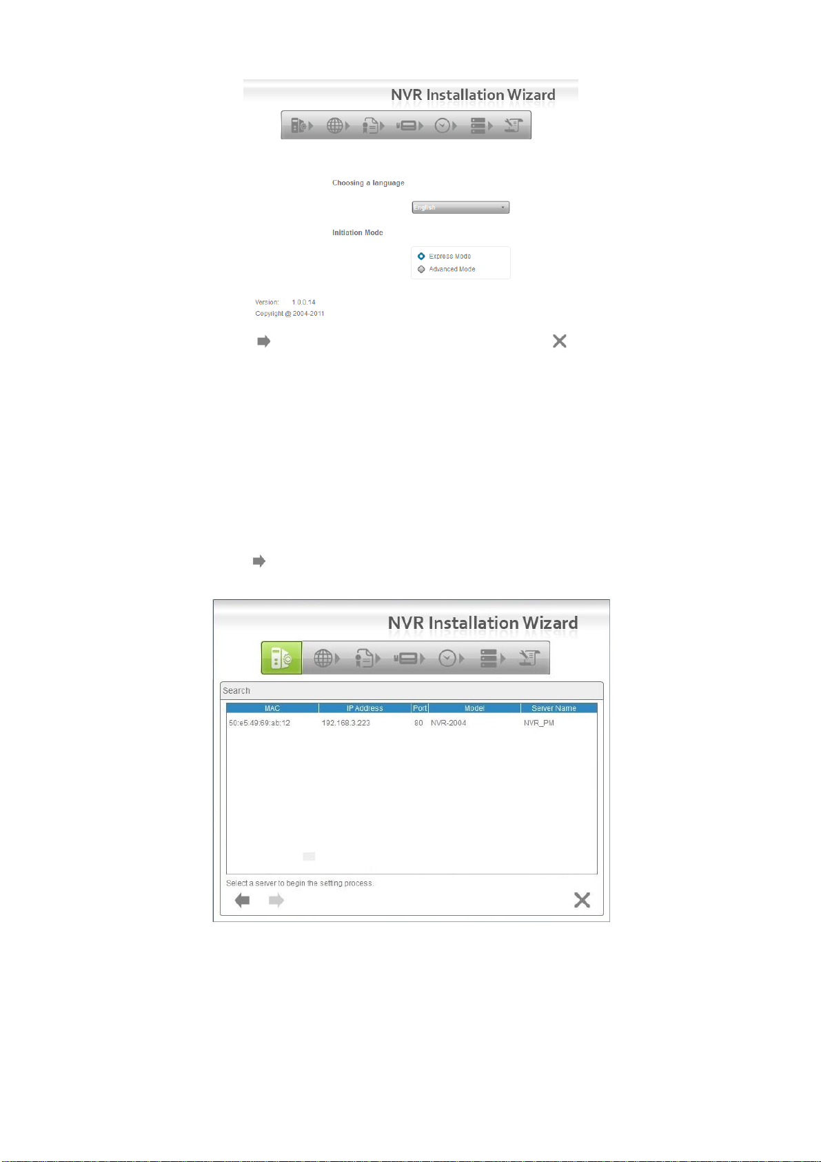
The software Installation Wizard performs the setup procedures on the unit.
After this procedure, you can begin using it.
1. Go to Start > NVR > NVR Install Wizard.
2. This program will show the default language setting and initiation mode.
3. Choose your preferred language and initiation mode, and then click the
button.
Page 12
11
Express Mode: In this mode, you don’t need to set up the network
settings, Date/Time and RAID level.
Advanced Mode: In this mode, configure all settings manually: network,
license, camera, Date/Time, upgrade notification, and RAID level.
4. The Installation Wizard program starts searching for all the network
devices on the LAN currently. Click on the newly connected NVR’s field, and
then click the button.
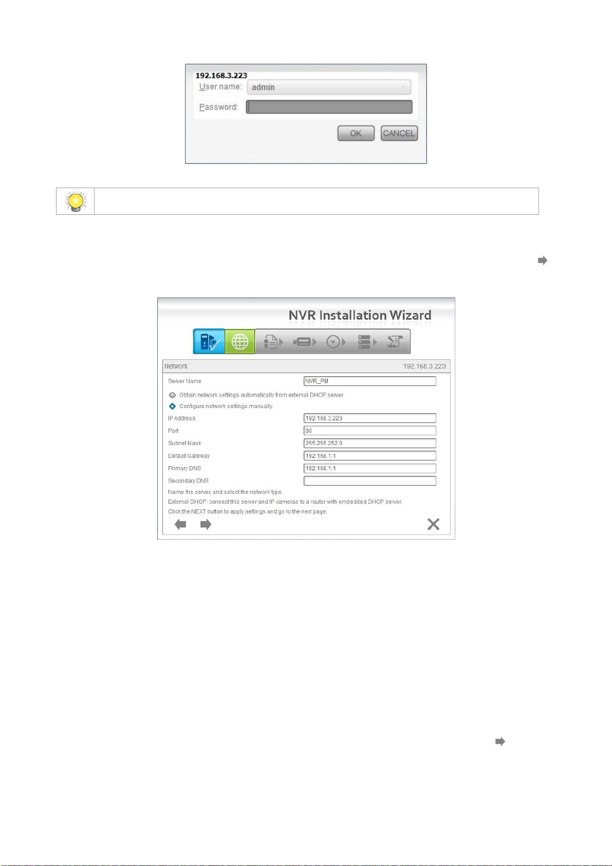
5. The NVR’s login screen will appear. Type in the password (default =
“admin”), and then click the OK button.
Page 13
12
The default Administrator password is “admin”.
6. Name this server (the NVR) and write down its IP Address for finding it on
the Internet in the future. Select the network type, and then click the
button.
Obtain network settings automatically from external DHCP server:
This function applies all settings which are automatically generated by the
DHCP server, such as IP, subnet mask, gateway, and DNS.
Configure network settings manually: This function lets you configure
the preferred settings one by one.
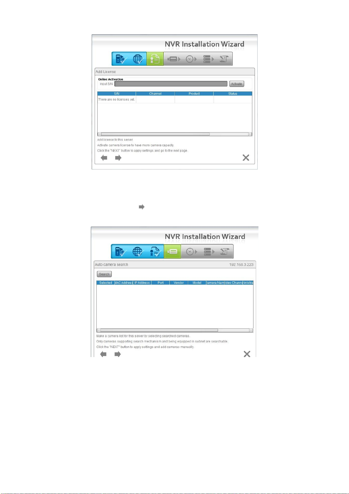
7. If you have obtained a license for additional camera channels, you should
enter the Serial Number (S/N) on this screen (see below) to activate the
additional channels. Click the Activate button and wait for the license to be
verified online. Wait for the license to be listed and then click the button
to save and proceed.
Page 14
13
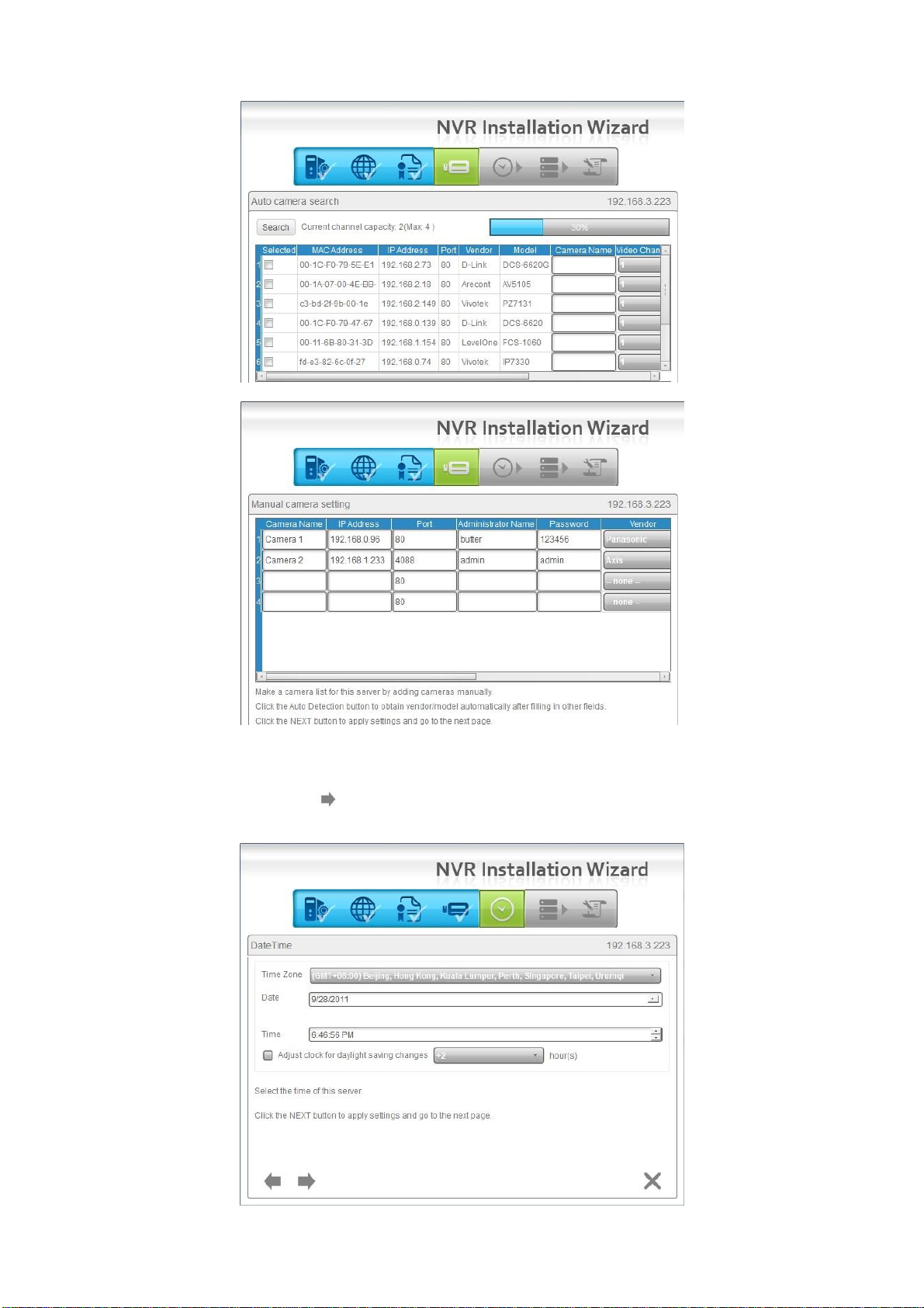
8. Add online cameras for this NVR. There are two ways of adding cameras –
either click Search and select from the search list, or manually configure
the cameras. Click the button after adding your cameras to the list –
this will apply the settings and take you to the Manual camera setup page.
Page 15
14
9. Set up the time zone, date, and time, and apply daylight saving changes if
needed. Click the button.
Page 16
15
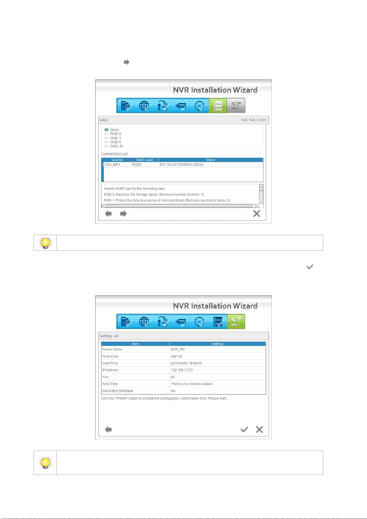
For a 2-bay unit, only RAID 0 and 1 are available.
Once the “FINISH” button is clicked, the unit will start working. In order to ensure the
stability of the unit, never pull any disks out when the system is running.
10. Follow the following instructions and select the RAID type you want to
create. Click the button.
11. Review your settings. If the settings are correct, click the Finish
button to exit the settings procedure and activate the system.
Page 17

16
1.2 LED Status Definitions
Function
LED Status
Power Status
Power-on: blue
Power-off: dark
System Status
Healthy: blue
Reset admin password: blue with blinking
Unhealthy or abnormal temperature status: orange
Reset to default setting: orange with blinking
Off: dark
HDD Status
Healthy: blue
Failed: orange
No disk: dark
Rebuilding: orange with blinking
eSATA Status
Healthy: blue
No disk: dark
Ethernet Status
Linking: blue
Accessing: blue with blinking
No linking: dark
Page 18
17
2. Settings
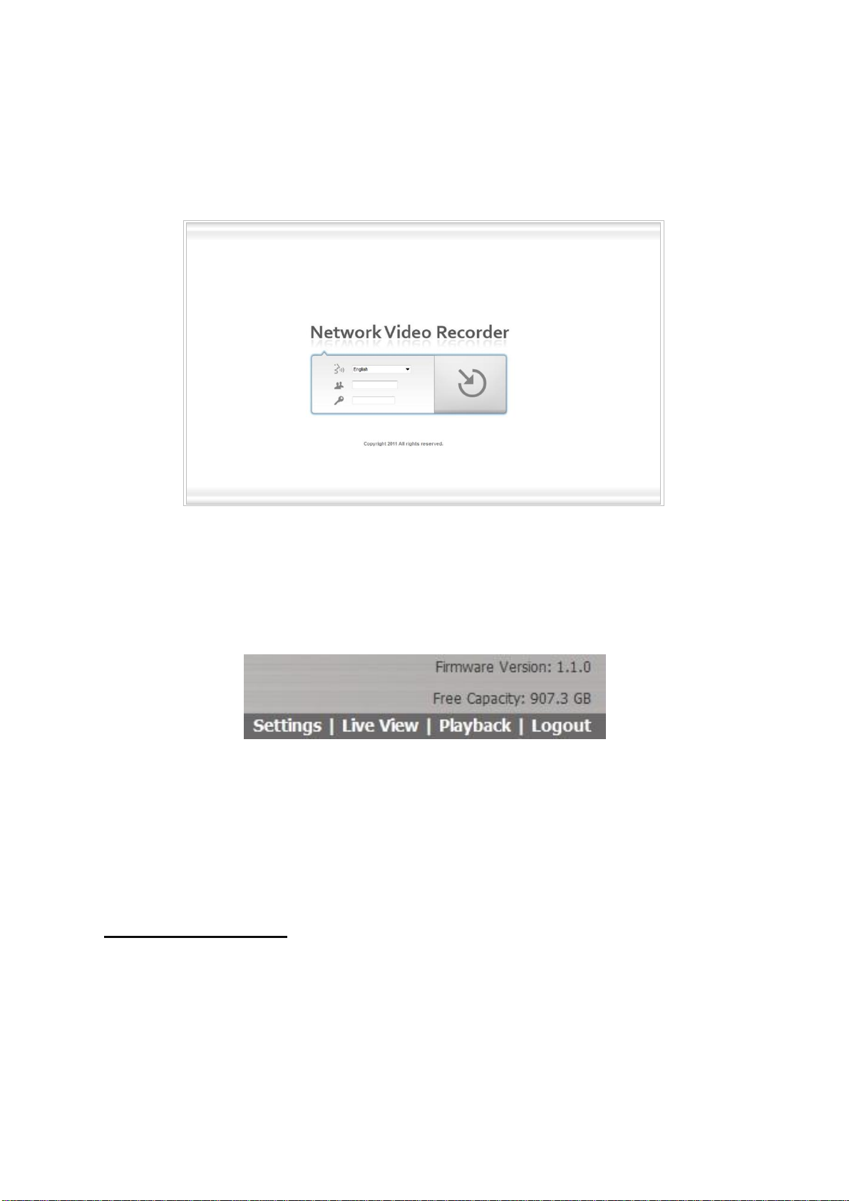
After setting up the unit, log into the DVR by entering its IP address in the
browser (Internet Explorer 7 and later). When connecting, choose your
language, enter the username and password, and then click the login icon.
There are four main menu categories in this DVR’s GUI: Settings, Live View,
Playback, and Logout. The shortcut buttons to these functions and their
submenus will be shown on the top of the page. The current firmware version
and free storage capacity are shown above the function list.
2.1 Camera Setup
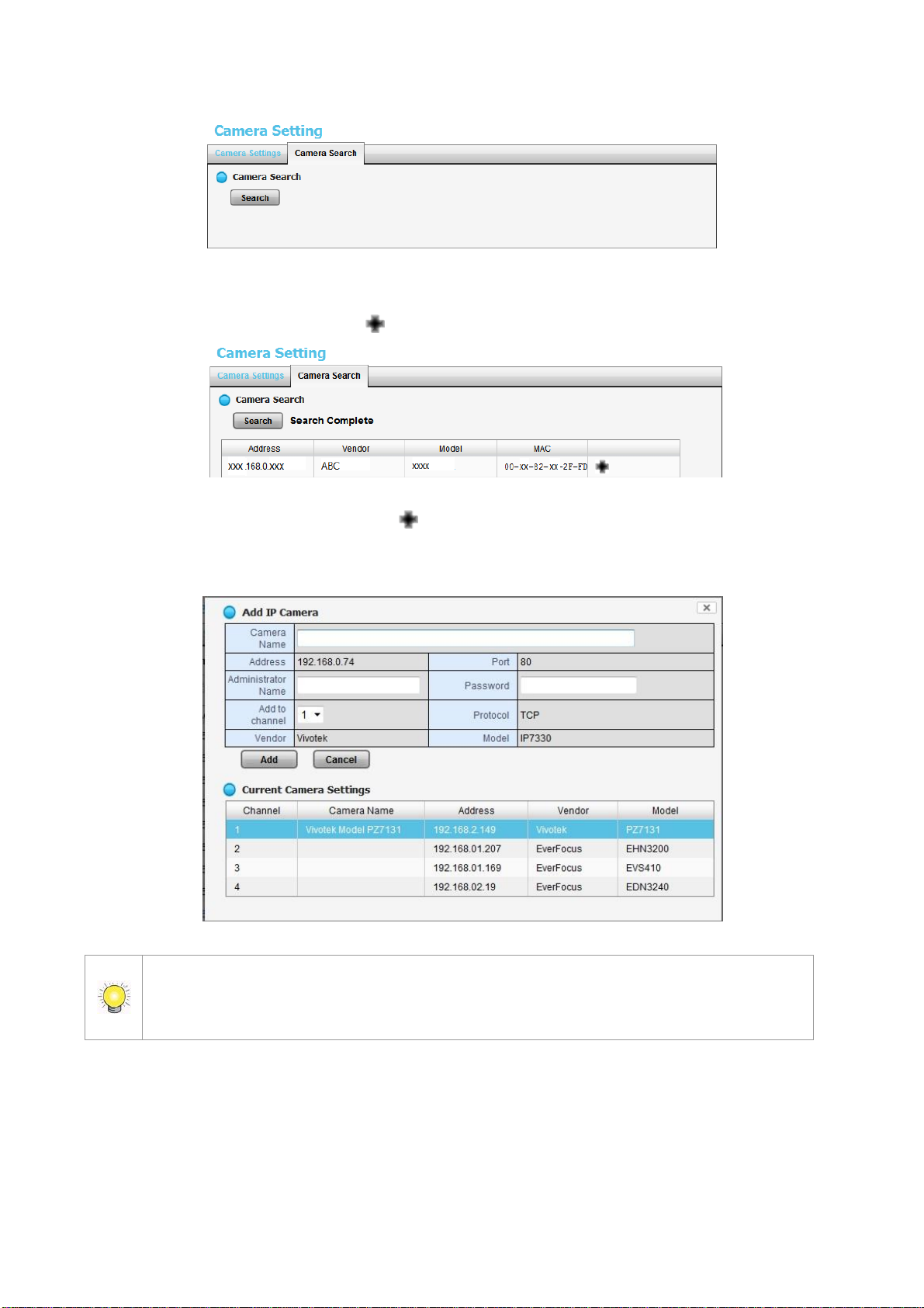
2.1.1 Add Cameras by Camera Search
The function enables the user to automatically search and add cameras in the
same network. There are two search mechanisms, one is UPnP, another is the
camera search tool. Before searching UPnP cameras, make sure that the
cameras possess UPnP functionality.
1. Open Internet Explorer and log into the unit.
2. Click Settings/IP Camera/Camera Settings.
3. Click the Camera Search tab.
Page 19
18
4. Click the Search button.
Note that the “username” field is called “Administrator Name” in this instance. This is
because admin-level control is required in this setup procedure to ensure smooth
interaction between the camera and the NVR.
5. The system will list all the currently available cameras. Select a camera by
clicking on it. Click the icon to add that camera to your camera list.
6. After clicking the camera’s icon, that camera’s setting page will pop up.
Insert the camera name, username, and password. Click on the “Add to
channel” tab and select the channel that you want to add the camera to.
7. Click the Add button to add the camera.
8. After clicking the Add button, the updated camera list will be displayed in
the Camera Settings display.
Page 20
19
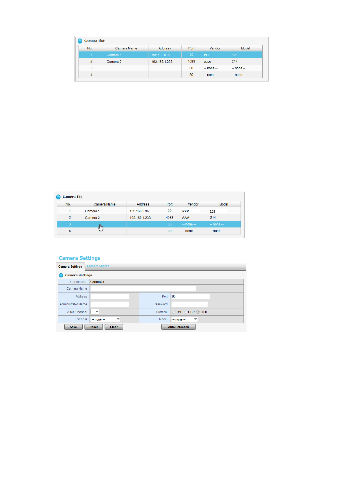
2.1.2 Add Cameras Manually
1. Open Internet Explorer and log into the NVR.
2. Click Settings / IP Camera / Camera Setting.
3. Click the Camera Settings tab. The Camera List will be displayed on the
bottom of the page.
4. On the Camera List, click on the number that you want to assign to the
camera (also called the “camera channel number”). Enter the camera’s
information into that number’s setup page by double-clicking on the
number’s field.
5. The camera channel number’s configuration field will open:
Camera name: The name of the camera channel.
Address: The IP address.
Port: The transmission port.
Administrator Name: Login username.
Password: Login password.
Video Channel (feeds per channel): Select the number of analog
cameras supported by one video server or select the number of IP
cameras possessing multiple lens/channels.
Protocol: Data transmission protocol.
Vendor: Camera vendor name.
Model: Camera model name.
Page 21

20
Note that the “username” field is called “Administrator Name” in this instance. This is
because admin-level control is required in this setup procedure to ensure smooth
interaction between the camera and the NVR.
6. Click the Save button.
Save: Save the configuration of this camera.
Reset: Return to the previous saved settings of the selected camera.
Clear: Set all the settings to their default values.
Auto Detection: After inserting the IP address, port, username, and
password, click this button to automatically detect other camera
information, including the Video Channel (feeds per channel), Protocol,
Vendor, and Model.
2.1.3 Modify Camera Information
1. Open Internet Explorer and log in to the unit.
2. Click Settings / IP Camera / Camera Settings.
3. Click the Camera Settings tab.
4. Click the camera which you want to modify.
5. Modify the information of this camera.
6. Click the Save button.
7. Use the same method to replace a camera if needed.
2.1.4 Modify Camera Parameters
1. Open Internet Explorer and log in to the unit.
2. Click Settings /IP Camera / Camera Parameters.
3. Click the Camera Parameter tab.
4. Click the camera which you want to modify on the camera list.
5. Modify the information of this camera.
6. Click the Save button.
Page 22
21
Camera Name: The name of the camera.
Video Format: Choose the type of format which this camera supports.
Frame rate: Select the frame rate of the camera.
Resolution: Select the resolution of the camera.
Quality: Select the image quality of the camera.
Audio: Check the Enable Audio option to view and enable audio
recording.
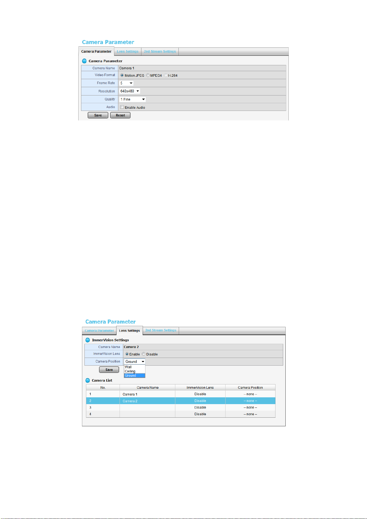
2.1.5 Set up Lens Settings
1. Open Internet Explorer and log in to the unit.
2. Click Settings / IP Camera / Camera Parameters.
3. Click the Lens Settings tab.
4. Click the camera which you want to modify in the camera list.
5. Modify the information of this camera.
6. Click the Save button.
Camera Name: The name of the camera.
ImmerVision Lens: Enable the option if ImmerVision lens is installed.
Camera Position: Select the position of the camera.
Page 23
22
If users enable the lens while lens is not installed correctly or not even installed, a
warning message will pop up as a notification if users are trying to operate lens on
liveview page.
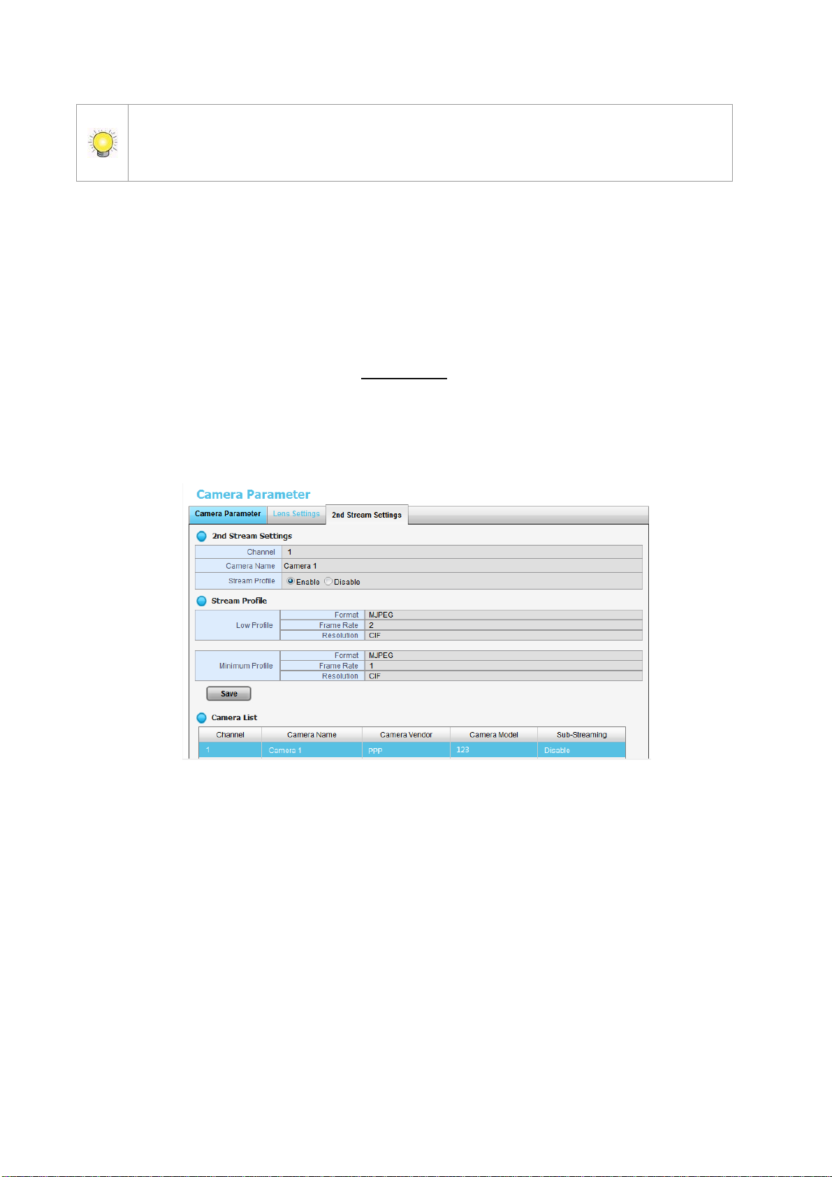
2.1.6 Set up 2nd Stream
The stream profile is designed for mobile clients and lower-fps live stream
display. Without stream profile integration, users cannot watch live video on
mobile clients nor select a lower fps stream for Live View. Further, for
performance considerations, we fix the resolution and frame rate for each
brand/series. You can refer to appendix for a supporting list.
1. Open Internet Explorer and log into the unit.
2. Click Settings / IP Camera / Camera Parameters.
3. Click the 2nd Stream Settings tab.
Stream Profile: The default status is Disable. If you want mobile client
user to access to this camera, you can select Enable, and click Save
button in the middle of the page.
Low Profile: The stream profile, under 300kbps, is designed for mobile
client single-view.
Minimum Profile: The stream profile, under 100 kbps, is designed for
mobile client multi-view.
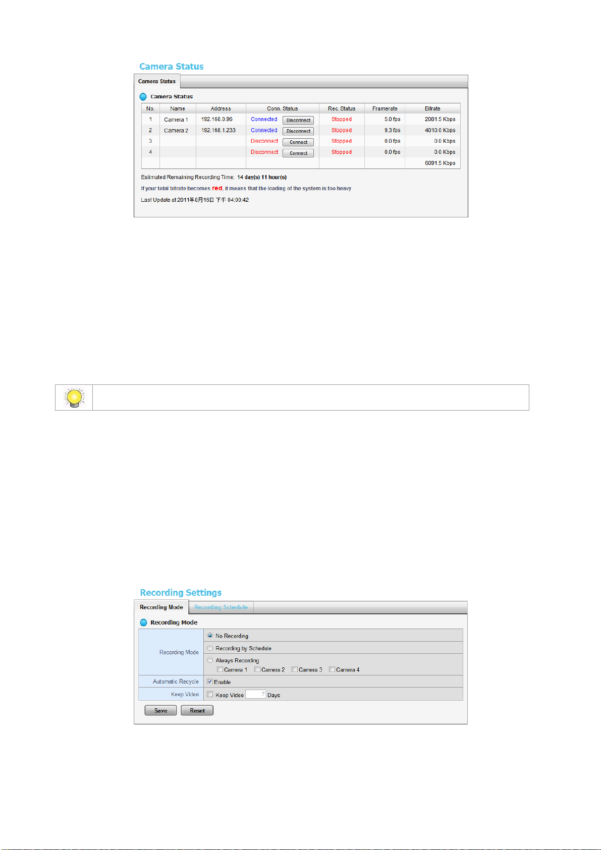
2.1.7 View Camera Status
1. Open Internet Explorer and log into the unit.
2. Click Settings / IP Camera / Camera Status.
Page 24
23
If your total bitrate becomes red, it means that the loading of the system is too heavy.
Conn. Status: The status of the connection. Click the Connect or
Disconnect button to change the connection status.
Rec. Status: The set recording schedule of this camera in this time.
Framerate: The frame rate of this camera.
Bitrate: The transmission bit rate of this camera.
Estimated Remaining Recording Time: Estimated remaining
recording time is dividing the current free capacity by dynamic total
bitrate.
2.2 Recording & Event Setup
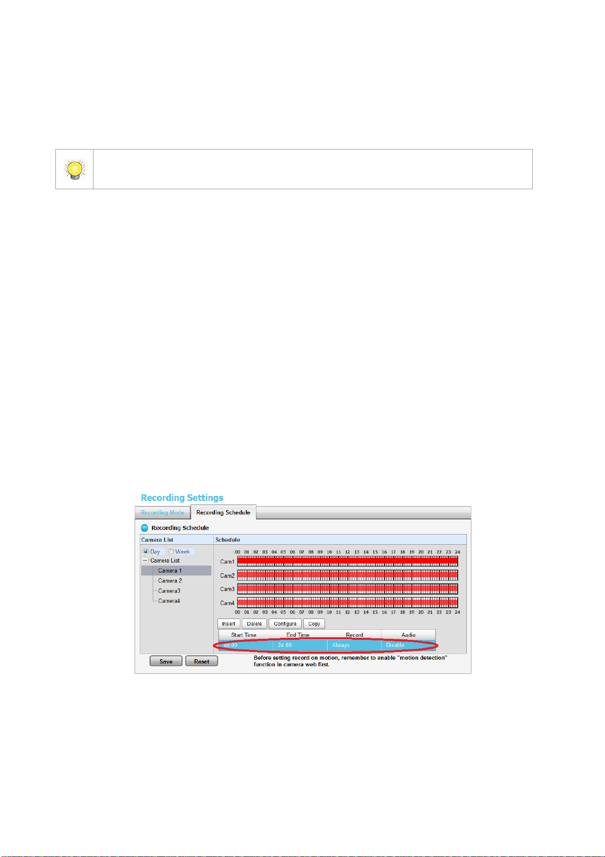
2.2.1 Recording Mode Setup
1. Open Internet Explorer and log in to the unit.
2. Click Settings / Recording & Event / Recording settings.
3. Click the Recording Mode tab.
4. If selecting Always Recording, the chosen cameras will begin to record
immediately.
No Recording: Turn off the recording.
Recording by Schedule: Recording by schedule.
Always Recording: Permanently turn on the chosen cameras.
Page 25
24
Automatic Recycle: Check the Enable option to recycle disk space
If you select both Automatic Recycle and Keep Video, Automatic Recycle will take
priority. In other words, the data will only be kept until the disk space is full.
automatically when the disk space is full.
Keep Video: Set a period during which the recorded video clips will be
kept intact.
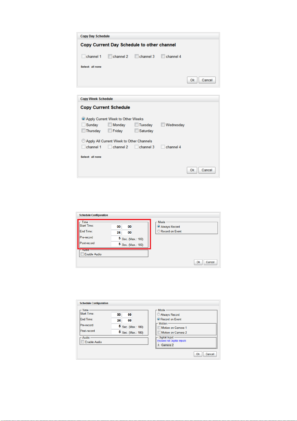
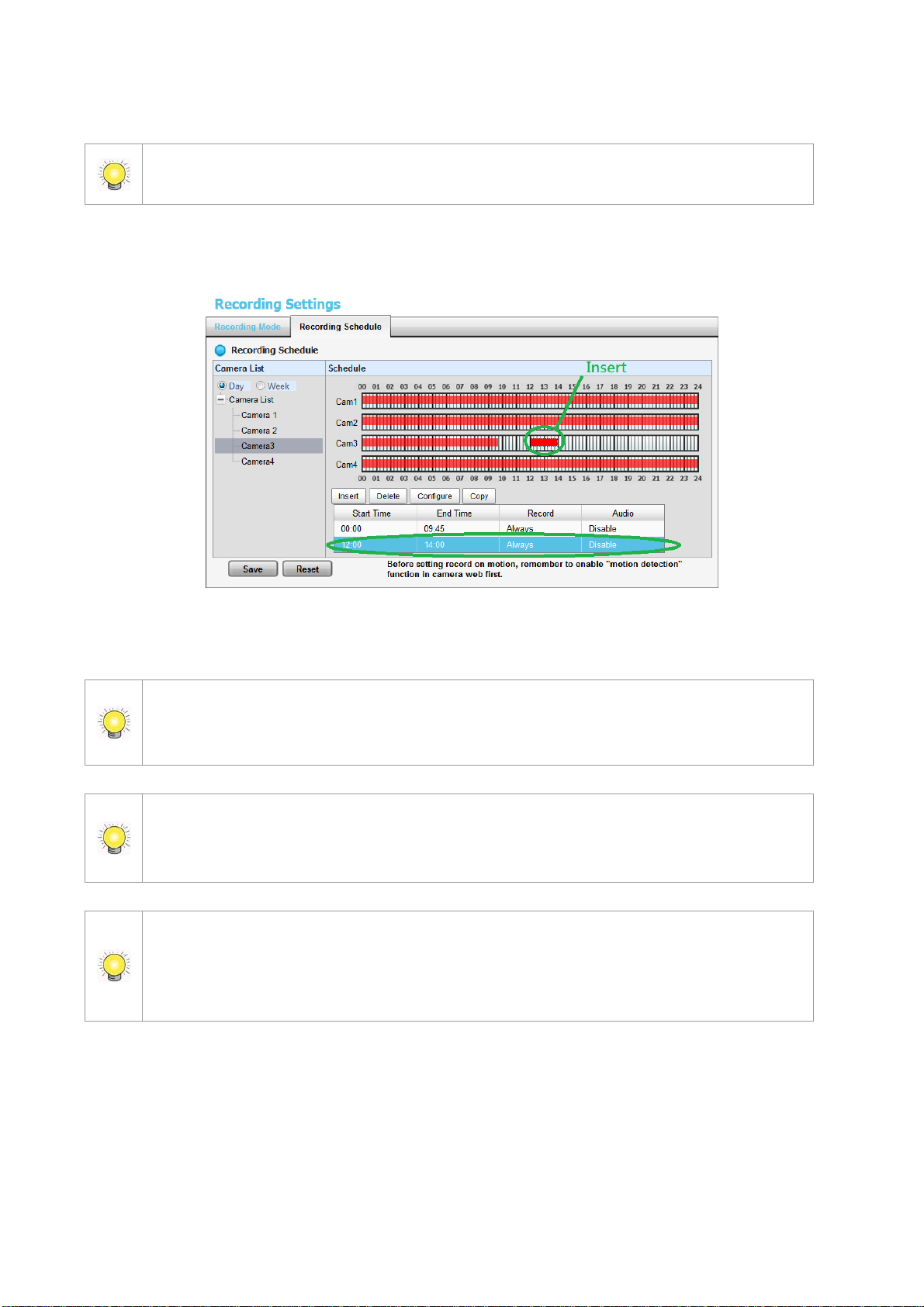
2.2.2 Recording Schedule / Event Setup
Instead of Always Recording, you can begin the recording by setting the
Recording Schedule.
1. Open Internet Explorer and log in to the unit.
2. Click Settings / Recording & Event / Recording Settings.
3. Click the Recording Schedule tab.
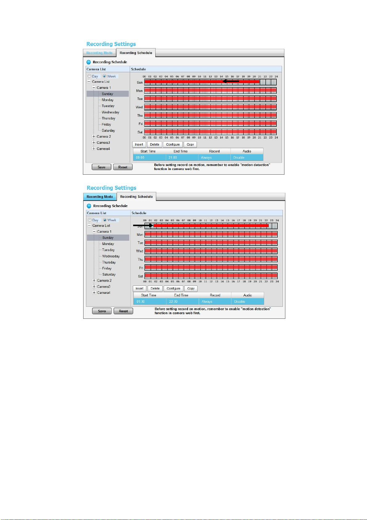
4. Check the Day or Week mode.
Day: Schedule the recording to turn the recorder on and off at the same
time every day according to your setting.
Week: Schedule the recording for each day of the week differently.
5. Click the schedule of the camera which needs to be modified.
6. Click the column at the bottom of the page.
Insert: Insert new schedules.
Delete: Delete the selected schedule.
Configure: Modify the schedule and recording mode settings.
Copy: Copy current Day Schedule to other channel(s); copy current
Week Schedule to other day(s) of a week or other channel(s).
Page 26
25
7. The default setting of the camera’s recording schedule is from 00:00 to
24:00. If you want to modify the time slot, click the Configure button to
modify the default settings first.
8. Choose the recording mode.
Always Record: Always record.
Record on Event: Record when events triggered. The event can be
Page 27
26
triggered by Motion or Digital input.
When setting the event Motion, please first ensure that the motion detection function
of the camera has been enabled.
When changing the motion detection settings of a camera, make sure to disconnect
your unit and that camera first. Once you have finished, re-connecting them will
update the settings in your unit.
When setting an event, Motion or Digital input can be triggered from other cameras.
This means that if the system detects motion or digital input from other cameras or I/O
Box, the camera will begin recording.
There is another way to set the schedule. If you want to change the recording time
length, drag the end of the time bar from 24:00 back to the length you wish, and then
drag the beginning of the time bar to the point at which you would like it to commence
recording. (You may also click the Insert button to add new schedules.)
9. If you want to add another new schedule, click the Insert button to add a
new one.
10. Click the Save button.
Page 28
27
Drag
Drag
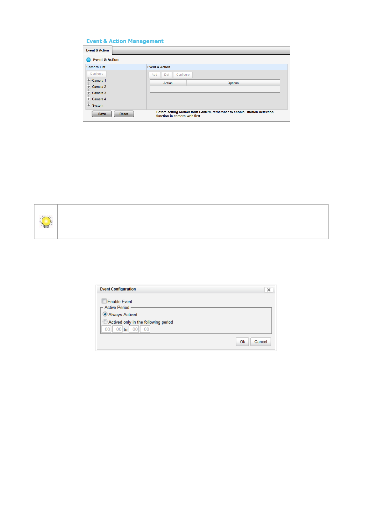
2.2.3 Camera Events and Responding Actions Setup
1. Open Internet Explorer and log in to the unit.
2. Click Settings / Recording & Event / Event & Action Management.
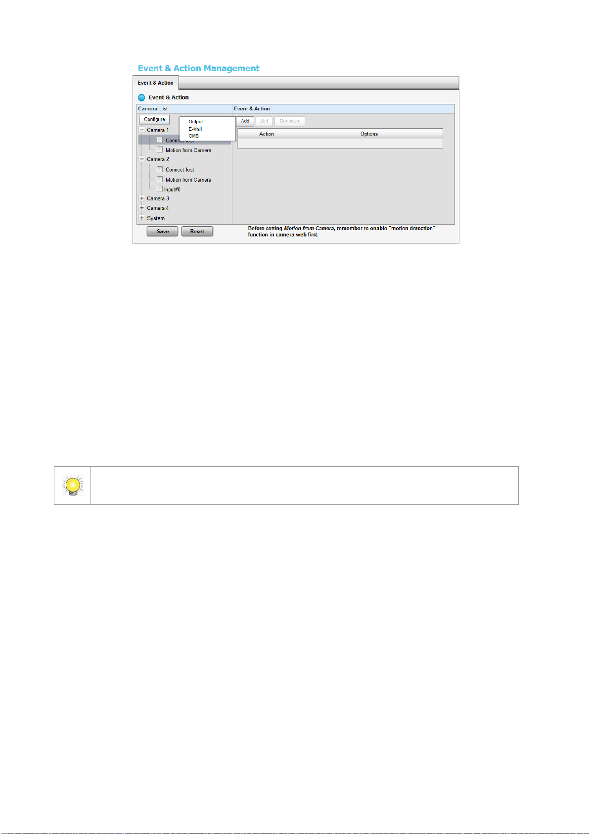
3. Choose the camera, and then select one of the events. The event list
depends on camera its own ability.
Page 29
28
When setting the event Motion from Camera, make sure to set up the camera’s
motion detection function first. Besides, event log will be recorded only if event is
selected on this page.
Connect lost: When a connection between the camera and this unit is
lost, the system will trigger an action.
Motion from Camera: When video motion is detected, the camera
triggers an action.
Input: Any external input can trigger an action.
4. Click the Configure button to enable the event and select the active
period.
Always Actived: The selected event is always active.
Actived only in the following period: The selected event is only active
in the designated time, which able to cover two days e.g. from 18:00 to
09:00.
I/O Type: Check one of the options of I/O type. N/O means normal open,
while N/C means normal close.
5. Click the Add button to set up the responding actions of this event.
Page 30
29
After selecting camera events, the event information will display on the screen when
it’s triggered.
Output: When an event occurs, the system will send an output signal to
other connected devices.
E-Mail: When an event occurs, the system will send e-mail notifications.
Make sure to add an e-mail address first.
CMS: When an event occurs, the system will send out a signal to CMS.
CMS will highlight this event.
6. Click the action, and then click the Configure button to modify the details
of that action if necessary.
7. Click the Save button.
2.2.4 I/O Box Input and Responding Action Setup
1. Open Internet Explorer and log in to the unit.
2. Click Settings / Recording & Event / Event & Action Management.
3. Click the Event & Action tab.
4. Select an input of I/O Box from list.
5. Click the Add button to set up the responding actions of this event.
6. Click the action, and then click the Configure button to modify the details
of that action if necessary.
Page 31

30
Output: When an input is triggered, the system will send an output
signal to other connected devices.
E-Mail: When an input is triggered, the system will send e-mail
notifications. Make sure to add an e-mail address first.
CMS: When an input is triggered, the system will send out a signal to
CMS. CMS will highlight this event.
Show on Camera: When an input is triggered, the system will show an
alert message on selected camera(s) of screen.
7. Click the Save button.
2.2.5 System Events and Responding Actions Setup
1. Open Internet Explorer and log in to the unit.
2. Click Settings / Recording & Event / Event & Action Management.
3. Click the Event & Action tab.
4. Click System to unfold the list of system events, and then select one of the
five events.
Page 32

31
E-Mail is the only one action to the event Daily System Report, Unable to access
FTP, Backup unfinished, Power-on Notification and Auto power-off
Notification. In addition to select a contact, remember to insert the time of sending
daily system report.
Abnormal disk status: When there is no enough disk space for
recording or when disk is abnormal for accessing, the system will trigger
an action.
Daily System Report: Enable users to know the system information,
HDD usage, and Disk status everyday through E-mail without accessing
to the unit to check.
Unable to access FTP: The action will be triggered when the connection
between the unit and FTP server is lost.
Backup unfinished: If there is any file which the system didn’t
complete the backup process, the file(s) name will be listed and send out
through E-mail after finishing the last file of this backup schedule.
Power-on Notification: Record the time as power was turning on.
Auto power-off Notification: If overheat was happened, users will be
notified that power is auto off via E-mail.
5. Click the Add button to set up the responding actions of this event. Follow
the steps in the previous section.
6. Click the Save button.
Page 33

32
2.2.6 SMTP Server Setup
1. Open Internet Explorer and log in to the unit.
2. Click Settings / Recording & Event / E-Mail.
3. Click the SMTP Server tab.
Server Address: SMTP (Simple Mail Transport Protocol) server IP
address.
Port: SMTP port.
Sender: Sender information.
Subject: The subject of the mail.
Body: E-Mail content.
SMTP Authentication: Before sending out an E-Mail, enter the user
name and password for SMTP authentication.
Username
Password
4. Click the Send Test Mail button and the system will send a test mail to the
sender. Check it after testing.
5. Click the Save button.
Page 34

33
2.2.7 Add Event Contacts
1. Open Internet Explorer and log in to the unit.
2. Click Settings / Recording & Event / E-Mail.
3. Click the Contactors tab.
Add Contactor: Add this new contact into the contact list.
Reset: Return to the latest saved settings of the contact list.
Save: Save this time modification of the contact list.
4. Insert the name of a new contact.
5. Insert the e-mail address of this new contact.
6. Click the Add Contactor button.
7. Click the Save button to save this modification of the contact list.
2.3 RAID & File Settings
2.3.1 Create a RAID Volume
In this system, the term RAID volume refers to one or more disk drives
working together as a RAID logical drive. You must create a RAID volume
before starting to record.
1. Open Internet Explorer and log in to the unit.
2. Click Settings / RAID & File System / RAID Management.
3. Click the Create tab.
Page 35

34
4. Choose the RAID level you prefer for your disk array.
5. Check boxes of disks and click the >> button to assign disk drives for this
volume.
6. Click the Create button.
7. A confirmation dialog pops up. Check the Yes, I want to create volume
with those disk(s) box, and click the Yes, create it button.
8. Creating RAID volume takes a while, depending on the size of disks and the
RAID level you choose. You can start recording during RAID creation.
Page 36

35
The RAID Volume will be functional on another unit if all disks of this volume are
moved to the unit.
After setting RAID level, you are not allowed to change neither the RAID level nor the
number of disks containing in this volume.
To reduce the possibility of having problems to access public folder via My Network
Places, before creating new disk volume or modifying volume, please delete the invalid
volume if any.
If you choose Express Mode when using the Installation Wizard, the disk(s) will be
set to RAID 1 (2 bay) or RAID 5 (4 bay) automatically unless the number of disks is not
enough for this RAID level.
2.3.2 View RAID Volume Status
RAID status refers to the disk drives on your unit and how they are arranged
into a RAID volume.
1. Open Internet Explorer and log in to the unit.
2. Click Settings / RAID & File System / RAID Management.
3. Click the RAID Status tab to view the status of your RAID Volume.
RAID Name: Name of your RAID, automatically assigned when it was
created.
Page 37

36
RAID Level: RAID 0, 1, 5, or 10, specified when it was created.
RAID Status: Functional is normal. Critical means there are some
problems on RAID volume, but the recording status is normal. Offline
means that no volume is found, so recording is stopped and you cannot
access your data either. File system error means that RAID volume is
existed but unmounted, so recording is stopped and you cannot access
your data either.
Capacity: Total, free, used data capacity of the RAID volume.
Update Time: The time of volume created/updated.
Devices: Total number of disks and the number of active, failed, spare
disks.
Format Progress: The status of RAID format
Recovery Progress: The status of RAID recovery
2.3.3 View Disk Drive Information
1. Open Internet Explorer and log in to the unit.
2. Click Settings / RAID & File System / RAID Management.
3. Click the RAID Status tab.
4. Click on a disk directly to view the information.
2.3.4 Modify RAID Volume
This function is designed for replacing a broken hard drive with a new one,
instead of modifying RAID level.
In the condition of critical RAID status, it’s a warning to show that one of disks
of this RAID volume may be damaged. Even though it’s no impact on the
recording function, you’d better to replace a new disk to make sure the volume
with data protection mechanism.
Page 38

37
This function is not applied to RAID 0, since there is no data protection mechanism by
its nature.
In case of any unexpected damage, we recommend users to unplug running HDD by
this method, which can be viewed as security hard drive remove.
1. Open Internet Explorer and log in to the unit.
2. Click Settings / RAID & File System / RAID Management.
3. Click the Modify tab.
4. Click on the volume you want to modify. The information of this volume will
be displayed under the Modify Volume section.
Page 39

38
5. After removing the damaged disk. Add a free disk to replace the damaged,
and click the Modify button.
6. A confirmation dialog pops up. Check the Yes, I want to modify this
volume box, and click the Yes, modify it button.
7. Modifying RAID volume takes a while, depending on the size of disks you
choose. Recording won’t be stopped during the modification, and the data
of this RAID volume is fully accessible.
Page 40

39
2.3.5 Delete a RAID Volume
1. Open Internet Explorer and log in to the unit.
2. Click Settings / RAID & File System / RAID Management.
3. Click the Delete tab.
4. Click the option button beside the RAID Volume you want to delete.
5. Click the Delete button.
6. A confirmation dialog pops up. Check the Yes, I want to delete this
volume box, and click the Yes, delete it button.
7. System will restart automatically after RAID volume is deleted
Page 41

40
When you delete a RAID Volume, all the folders in the RAID volume and all the data
saved in the folders will be deleted. Backup any important data before deleting a RAID
Volume.
2.3.6 Format
Neither pressing reset button nor loading default setting, the data of RAID
volume won’t be deleted, which implies that format is the only way to clean
the RAID information from disks.
1. Open Internet Explorer and log in to the unit.
2. Click Settings / RAID & File System / RAID Management.
3. Click the Format tab.
4. Click the option button beside the RAID Volume you want to format.
5. Click the Format button.
6. A confirmation dialog pops up. Check the Yes, I want to format this
volume box, and click the Yes, format it button.
7. System will restart automatically after volume format is complete.
2.3.7 Modify the “My Network Places” Protocol Settings
There are another two ways to access the recorded data in the unit: through
Workgroup or through FTP.
Page 42

41
1. Open Internet Explorer and log in to the unit.
2. Click Settings / RAID & File System / Protocol Control.
3. Click the Windows tab.
4. Check and enter the unit’s information.
5. Click the OK button.
Services: Enable to let users access this unit through Windows Explorer.
Server Name: The name of this unit, which is set in the Setup tab of the
Network Setup function.
Server Description: The name which will be displayed in Windows
Explorer.
Domain or Workgroup Name: The name of this unit’s workgroup.
2.3.8 Modify the FTP Protocol Settings
1. Open Internet Explorer and log in to the unit.
2. Click RAID & File System / Protocol Control.
3. Click the FTP Sharing tab.
4. Check and enter the settings of this unit.
5. Click the OK button.
Services: Whether users can access this unit through FTP or not.
Command Port: The port for commands between a server and a client.
Page 43

42
Passive Ports: The data transmission port of passive mode.
The system backups recorded video files one by one. If the connection between the
unit and FTP server is normal, but some problems of FTP causes the system unable to
write files on FTP, the system would try each file three times before starting to backup
2.4 Auto Backup
This feature enables you to automatically backup the recorded video of the
previous date to FTP site. There are two steps to enable the function, one is
Set up Backup Schedule, another is Set up Backup Server.
2.4.1 Set up Backup Schedule
1. Open Internet Explorer and log in to the unit.
2. Click RAID & File System / Auto Backup Management.
3. Click the Backup Schedule tab.
4. Set up backup schedule, select the backup channels, and check the Enable
option to enable Auto Backup.
Auto Backup: Check the Enable option to enable this function.
Daily Backup Time: The daily scheduled time to start backup process.
Start Time: The start time of recorded video of the previous date.
End Time: The end time of recorded video of the previous date.
Camera: Select the channel(s) to backup.
5. Current Event Settings shows the condition of the events of auto
backup – enable or disable. Follow the steps of System Events and
Responding Actions Setup to configure the event & action.
Page 44

43
the next file. If the connection is lost, the system would wait for the connection, so no
file would be skipped.
2.4.2 Set up Backup Server
1. Open Internet Explorer and log in to the unit.
2. Click RAID & File System / Auto Backup Management.
3. Click the Backup Server tab.
4. Set up the FTP server and create a folder for backup files. The folder format
is “FolderName”, “FolderName/SubFolderName”, and so on.
For example: AutoBackup/NVR
5. After setting up all the information, click the Test FTP button and the
system will create a folder to FTP. Check it after testing. In this case, the
route of the tested file will be:
ftp://test.dnsalias.com/AutoBackup/NVR/test
Page 45

44
6. Click the Save button.
Make sure the FTP account with privileges of administrator who is able to upload,
rewrite, delete files, and create new folder. Besides, make sure the FTP server has
enough space for auto backup.
To avoid the failure of auto backup, please check the normality of FTP server regularly
(e.g., enough space for video, system conditions.)
2.5 Network Setup
2.5.1 View Network Status
1. Open Internet Explorer and log in to the unit.
2. Click Network Setup / Network Setup.
3. Click the Information tab to view the unit’s network information.
2.5.2 Network Settings
1. Open Internet Explorer and log in to the unit.
2. Click Network Setup / Network Setup.
3. Click the Setup tab to set up the network settings of your unit.
Page 46

45
Because of the internal data modifications required, it takes a few seconds to change
the name of your unit. Log in again after configuration activated.
Server Name: Name your unit.
Internet Protocol: Choose to obtain an IP address from external DHCP
server automatically, or configure the IP address manually.
IP Address: IP address of this unit.
Subnet Mask: Subnet mask address.
Default Gateway IP Address: Gateway IP address.
Primary DNS: Primary DNS (Domain Name System) address.
Secondary DNS: Secondary DNS address.
4. Click the DDNS Setup tab to enable Dynamic Domain Name Server
function, allowing you to connect unit with dynamic IP address.
Page 47

46
2.5.3 Auto Port-Forwarding
This function is designed for saving time in port configuration on router if users
want to access the unit (in LAN) from WAN. Once enabling UPnP Service on
router, users can do port-forwarding for setting page (default: 80), liveview
(default: 5150), playback (default: 5160), and CMS (default: 5170)
automatically.
1. Open Internet Explorer and log in to the unit.
2. Click Network Setup / Network Setup.
3. Click the UPnP Port-Forwarding tab.
4. Click the Search button, and the searched routers will be listed.
5. Select the searched router, and all UPnP ports configured on this router will
show under the UPnP Port Forwarding List.
Page 48

47
For security reason, the privilege of UPnP port-forwarding is LOWER than
port-forwarding configured on router. Therefore, if the ports have been used on
router, we are unable to know before finding out access failure.
6. After selecting one of searched routers, click the icon to set up
port-forwarding to this router automatically. You will find ports of setting,
liveview, playback and CMS are listed.
Page 49

48
UPnP port-forwarding is for temporarily use only. Most of UPnP router will clean up all
UPnP ports after router reboots. Furthermore, for some routers, if the port you want
to add has already been used for other devices in the same way (UPnP port
forwarding), this “enable” action will cover over the settings.
2.5.4 Network Service Setup
1. Open Internet Explorer and log in to the unit.
2. Click Network Setup / Network Service.
3. Click the Web Service tab
4. Set up a port for this unit and click the Save button.
5. Click the Live View & Playback Service tab.
Live Streaming Server
Port: Live streaming transmission port.
Maximum Connections: Maximum connections from remote access.
(Max: 64)
Playback Server
Page 50

49
Port: Playback transmission port.
When setting Maximum Connections in Live Streaming Server settings, 1 connection
means that one user connects to one camera. If the maximum connections value is
set to 16, and each user connects to 4 cameras, the allowed connections per user will
become 4, rather than 16.
Maximum Users: The number of users who can access playback
functions at the same time. (Max: 8)
Log Access: Check to record playback access information on NVR Log
page, including access time, playback video channels, and time frame.
Allowed/ Blocked List
Allowed List: Only IP addresses from the allowed list are allowed to log
in.
Blocked List: IP addresses from the blocked list will be unable to log in.
2.5.5 CMS Service Setup
1. Open Internet Explorer and log in to the unit.
2. Click Network Setup / Network Service.
3. Click the CMS Service tab.
CMS Server: Check the Enable option to enable CMS service.
Port: the port number through which the CMS connects to this unit.
Maximum Connections: The maximum number of allowed CMS
connections.
2.6 Management
2.6.1 View the List of Users
1. Open Internet Explorer and login the unit.
2. Click Management/ User Management.
3. Click the Create New Users tab.
Page 51

50
4. The list will be displayed on the bottom of the page.
The Administrator will be the only user who can use all of the functions. There is a
default administrator account in the system, and you cannot create neither another
2.6.2 Create New Users
1. Open Internet Explorer and login the unit.
2. Click Management/ User Management.
3. Click the Create New Users tab.
4. Insert the username of this new user.
5. Insert the password of this new user.
6. Choose the group of this user.
Power user: Power user can do all the settings except the Network
Settings, RAID Settings, and Management function.
User: User just can change his/her password and do the live view and
playback functions.
Guest user: User can do live view and playback function only.
7. Select the live view cameras which this user can access.
8. Select the playback channels which this user can access.
9. Check whether this user can backup or delete recorded data.
10. Click the Create New User button to finish it.
Page 52

51
“Administrator” account, nor another username named “admin”.
2.6.3 Modify User Information
1. Open Internet Explorer and log in to the unit.
2. Click Management / User Management.
3. Click the Modify Users tab.
4. Click one of the users in the User List on the bottom of this page.
5. Change the group of this user.
6. Select the live view cameras which this user can access.
7. Select the playback channels which this user can access.
8. Check whether this user can backup or delete recorded data.
9. Click the Modify User button to finish it.
2.6.4 Change a User’s Password
1. Open Internet Explorer and log in to the unit.
2. Click Management / User Management.
3. Click the Change Password tab.
Page 53

52
4. Choose the user.
5. Enter a new password.
6. Enter this new password again.
7. Click the OK button.
2.6.5 Delete Users
Except for the administrator, you can delete any users with the following steps.
1. Open Internet Explorer and log in to the unit.
2. Click Management / User Management.
3. Click the Modify Users tab.
4. Click the Delete icon of the user you want to delete.
5. In the confirmation box, click the OK button.
2.6.6 Online License Activation
There are two types of license currently, camera license for 2/8ch-device and
POS license for all series. With the camera license upgrade, the 2ch-device will
possess up to 4ch capacity, while 8ch-device will possess up to 16ch capacity.
With the POS license upgrade, users can use POS function.
There are two ways to activate license, online and offline.
1. Open Internet Explorer and log in to the unit.
2. Click Management / License Management.
Page 54

53
3. Select Online as the Activation Type, input serial number, and click the
Activate button.
4. The license will be updated in License List if activated successfully. System
will reboot automatically.
2.6.7 Offline License Activation
If the device is set up in Intranet (Local LAN) without Internet connection,
there is another way to activate license.
1. Open Internet Explorer and log in to the unit.
2. Click Management / License Management.
Page 55

54
3. Click the Export button under the section of Offline Activation to export
the information of this unit.
4. Download dialog pops up. Save the request file and take it to other PC
which is connected to the Internet. Furthermore, the PC should be installed
OffLineTool.exe which can be found from NVR toolkit.
5. Execute the OffLineTool.exe in that PC with Internet connection, and select
the request file offline.req.
Page 56

55
6. Input the serial number, click the Activate button, and save the .dll file
offline_license.dll.
7. Import the license file to the unit.
8. The license will be updated in License List if activated successfully. System
will reboot automatically.
2.6.8 View the Event Log
1. Open Internet Explorer and log in to the unit.
2. Click Management / Log System to find the event list of your unit.
Page 57

56
The NVR Event Log will be recorded only if event is selected on Event & Action
Management page. As for user access information, please go to Network Service
to check Log Access box to enable this function.
There are four kinds of event which will be listed on this page.
Hardware Log: The log information of the operations to your unit, such
as reboot or shutdown.
NVR Log: The log information of the NVR system, such as system,
recording, user access information, POS and auto backup.
NVR Event Log: The log information of the “Event & Action
Management”, such as motion detection or camera connection lost.
Backup and Export Log: The log information of the track of video data
exported and backup.
2.6.9 Save Unit Configuration
Save configuration can let you save the settings of this unit. These settings
can be applied to other units, which will let you set other units more easily.
1. Open Internet Explorer and log in to the unit.
2. Click Management / Save / Load Configuration.
3. Click the Save Configuration tab.
Page 58

57
4. Check the box of E-Map Settings or POS Settings if you want to keep the
configuration.
5. Click the OK button.
6. The configuration file will be generated into the chosen folder.
2.6.10 Load Unit Configuration / Default Settings
Load configuration can let you apply another unit’s settings to the current unit;
Load Default Settings will revert all of the unit’s settings back to the default
factory settings.
1. Click Management / Save / Load Configuration.
2. Click the Load Configuration tab.
3. Follow the direction to Load Default Settings or Load Configuration.
For the former, uncheck the box of Network Settings to keep the IP
address; for the latter, check the box of E-Map Settings or POS Settings
if you want to restore the configuration.
4. Click the Load button.
5. A confirmation dialog pops up. Click the OK button to begin to load the
settings into your unit.
Page 59

58
If there is POS database existed in the unit, loading configuration with different POS
application config is likely to make the original POS data unsearchable.
If the saved configuration is without E-map or POS settings, selecting loading
configuration with E-map/POS settings will lead you get the default. The original E-
map/POS settings (if any) are covered and untraceable.
User account and privilege will be kept even if loading default settings, while
camera settings, recording schedule, event & action settings, E-mail setting and
server settings won’t be. RAID information will always be kept whether loading
default settings or loading configuration.
2.7 System
2.7.1 View System Information
1. Open Internet Explorer and log in to the unit.
2. Click System / System Information.
The system information includes the following items.
Operating System: Embedded Linux
NVR Version: NVR system version
Camera package version: Camera package version
CPU: CPU model number
MAC Address: MAC address of this unit
CPU Temperature
System Fan Speed
Locate: Click to trigger the buzzer to let you know where the unit is
Page 60

59
2.7.2 Smart Fan Control
1. Open Internet Explorer and log in to the unit.
2. Click System / System Settings.
3. Click the Fan Control tab.
4. Check the Enable or Disable option.
5. Click the OK button.
2.7.3 Buzzer Configuration
There is a buzzer in the unit. When the unit finishes booting or when a problem
is detected, this buzzer will sound. This buzzer is enabled by default. You can
disable/enable this buzzer with the following steps. (We recommend that this
buzzer should be enabled.)
1. Open Internet Explorer and log in to the unit.
2. Click System / Settings.
3. Click the Buzzer tab.
4. Check the Enable or Disable option.
5. Click the OK button.
2.7.4 UPS Setup
This feature enables you to tell your unit how long to run on APC
Uninterruptable Power Supply (UPS) battery power and when to shutdown,
Page 61

60
after power failure.
1. Attach the APC UPS to one of the unit’s USB ports.
2. Open Internet Explorer and log in to the unit.
3. Click System / Settings.
4. Click the APU UPS tab.
5. Check one of the options:
Disable: Run until the UPS battery is depleted
System shutdown as power of the UPS remains __ %: Run until the
UPS battery remains this percentage.
System shutdown as power of the UPS remains __ min.: Run until
the UPS battery remains the certain period of time.
6. Fill in the specific value if you choose the last two options.
7. Click the OK button.
2.7.5 Upgrade the System
1. Open Internet Explorer and log in to the unit.
2. Click System / Upgrade.
3. Click the Firmware Upgrade tab.
Page 62

61
When you modify the date or time of the system, the system may find the wrong data
when searching the recorded data. Backup the recorded data before changing the
time.
4. Browse the FW for upgrading and click the OK button.
5. A confirmation dialog pops up. Click the OK button to start upgrade
process.
6. After upgrade, the system will restart. You need to re-access the unit again
after this.
2.7.6 System Date and Time Setup
1. Open Internet Explorer and log in to the unit.
2. Click System / Date/Time.
3. Click the Setup tab.
4. Choose the year, month, day and time.
5. Click the OK button to restart the system to activate the changes.
2.7.7 Daylight Saving Time Setup
1. Open Internet Explorer and log in to the unit.
2. Click System / Date/Time.
3. Click the Time Zone tab.
Page 63

62
During system restart, none of your files will be accessible from your
desktops/laptops.
4. Check the Adjust clock for daylight saving changes option and select
the time change of daylight saving time in your location.
5. Click the OK button.
2.7.8 Restart the Unit
1. Open Internet Explorer and log in to the unit.
2. Click System / Reboot/Shutdown.
3. Check the Reboot option.
4. Click the OK button.
5. A confirmation dialog pops up. Click the OK button to reboot the unit.
The restart procedure runs automatically. When the unit is fully online:
The System Status LED turns blue.
The buzzer beeps one time (if the buzzer is enabled).
2.7.9 Shut Down the Unit
The only time you need to shut down the unit is to replace the disk drive
cooling fan or the power supply. During and after the shutdown, none of your
files will be accessible from your desktops/laptops. There are two ways to
shutdown the unit.
Shutdown by Software
1. Open Internet Explorer and log in to the unit.
2. Click System / Reboot / Shutdown.
Page 64

63
If the system is crashed and stocked, you can press the power button and hold it for
10 seconds to force to cut off the power directly. We don’t recommend to do it if the
system work properly.
3. Check the Shutdown option.
4. Click the OK button.
5. A confirmation dialog pops up. Click the OK button to shutdown the unit.
Direct Shutdown
1. Open the lid of the unit.
2. Press and hold the power button for 2 seconds and release your hands
when the buzzer is beeping once.
3. System will begin the shutdown process, which takes about 30 seconds to
few minutes depends on number of recording channels and other factors.
Page 65

64
3. POS
Terms
Definition
POS Original
Data
Original data from POS. Usually with a lot of
symbols and no line feed.
POS
Transaction
Filtered result by user-defined tag-filter.
POS Box
SCB-C31A
Input
RS232
Output
Ethernet
DC In
DC +10V to +15V
Power consumption
500 mA
Operating
Temperature
-20 to 65℃
Operating Humidity
0-90 % Non-Condensing
3.1 Introduction
3.1.1 System Introduction
POS, a Point of Sales Systems based on NVR, provides financial transaction’s
surveillance solution in one central system. The architecture is as below; POS
transaction data flows to NVR by Ethernet. Each Cash Register with an external
receipt printer is connected by DB9 cable. The transaction information
delivered in R232 format can be converted to Ethernet through SCB-C31A POS
data capture converter.
Definition of Terms
Product Specification
Page 66

65
Baud Rate
110 bps to 230.4 kbps
Data Bits
5, 6, 7 or 8
Stop Bits
1, 1.5 or 2
Parity
None, Even, Odd, Mark, Space
Flow Control
None, RTX/CTS, XON/XOFF, DTR/DSR
There are two kinds of serial cable: Straight pass-through and Null-Modem. The
connection between SCB-C31 POS Data capture box and Y-cable must be null modem
(in package).
SCB-C31A
Cash register
Printer
Null Modem
Y-cable
Ethernet
Provided by printer
F
F
M
M
F
3.1.2 Hardware Installation – SCB-C31A
To connect Cash Register, Printer, and SCB-C31A POS data capture converter
together, please follow below steps:
Step 1: Please refer the user manual to setup Cash Register and printer.
Step 2: Using a “Y-shape” DB-9 cable, one DB-9 female connect to POS
system and one DB-9 male connect to the receipt printer Y-shape
(provided by Printer vendor).
Step 3: Using another DB-9 female connect to SCB-C31A POS Data Capture
R232/Ethernet converter with Null modem.
Step 4: Check the system switch of the SCB-C31A is switched to OFF-OFF
position.
Step 5: Connect SCB-C31A with power source.
Step 6: Connect SCB-C31A with internet port by RJ45 LAN cable.
Page 67

66
Each time you switch the page of the web, please click Save at first. If you leave this
page without saving, all changes will be ignored.
The LED Indicators:
LINK LED: Ethernet cable connection and data active.
RUN LED: System is ready (Blinking).
Serial 1: Transiting/Receiving Indicator.
3.1.3 Software Installation – SCB-C31A
Step 1: Use IE-browser to setup SCB-C31A, the default IP address is
192.168.1.1
Step 2: Setup IP address and password in Server page, and click the Save
button.
Page 68

67
Step 3: Setup Password if needed. Password is only using to activate a security
Please write down the Serial number and MAC address, these two parameters are
necessary when user forget your password.
Every time you change the configuration of SCB-C31, please check above setting,
especially maximum connection and Remote IP address to avoid connection fail.
feature on the serial server. Once a password is entered it will be
required to access the menu and make change of configuration when
access.
Step 4: Setup according to your POS or Cash Register. Usually all devices are
default setting, you can reserve your time to pass this step.
Step 5: Please restart/reset the box after changing configurations to active
setup.
To reset the unit manually apply power, insert a small plastic tool, and
press lightly depressing reset located between the switch. Hold for 3
seconds and release. The Link and Run light will go out and turn back
on. The SCB-C31A will revert to the last setting.
3.1.4 Connection via TCP Client
If the cash register possess network, please install system according to
following diagram and purchase a POS license to activate this function.
Page 69

68
NVR
3.2 Software Setup
3.2.1 Activate POS License
If you are not the SCB-C31 user, you need to activate POS license before
starting the following settings, please refer to License Activation for details.
3.2.2 NVR POS Setting
1. Open Internet Explorer and log in to the unit.
2. Click POS & I/O / POS Settings.
3. Click the Settings tab to set POS application.
Page 70

69
Data Source: List of all the data sources.
Insert: Click to insert POS and do the POS settings. See Insert
POS Setting for details.
Delete: Click to remove the selected POS from the list. See Delete
POS Device for details.
Configure: Click to configure the selected POS and modify the POS
settings. See Configure POS Setting for details.
POS info: The setting information of the selected POS on this window.
Name: Name of the POS data source.
IP: IP of the POS data source.
Serial Box: The serial box data source used.
Tag Filter: Tag type to filter the data from POS. See Tag Filter for
details.
Associated Cameras: List of all the associated cameras of the selected
POS.
4. Click the OK button to finalize the modification.
3.2.3 Insert POS Setting
1. Click Insert button to open the POS Setting window.
2. Set up basic data source, including Name, Model, IP address, and Port.
There are three types of models.
Page 71

70
SCB-C31: The device possesses one POS license, and should be
equipped with the cash register not working as TCP server.
SCB-C31A: The difference from SCB-C31 is not possessing one POS
license, so user should activate POS license.
TCP Client: Cash register possesses with network, so no need to have
SCB-C31A as a converter. POS license is needed.
3. After setting, click Test Connection to test POS device connection.
4. Set up Miscellaneous options, including Record POS Transaction and
Display on Video Preview.
Record POS Transaction: Select this checkbox to record POS
transaction data. Users are allowed to search the POS data.
Display on Video Preview: Select this checkbox to display POS
transaction overlay on associated camera live video. Two types of
transaction data display time:
Name: Name of the POS data source.
Always: Keep transaction data on video until receiving next
transaction date.
Last for ___ seconds: Each transaction data only lasts on video for ___
seconds after receiving the last data of transaction.
Page 72

71
5. Select Tag Filter. See Tag Filter for details.
6. Select the camera of Associated Cameras to display POS transaction data
overlay on live video.
7. Set up display area for each camera video in Display Region Definition.
Default: The default display area is in the upper left corner of video
image.
User Define: Enable User Define, and define display area by dragging
rectangle
8. Click the OK button to save.
3.2.4 Delete POS Device
1. Choose POS device.
2. Click Delete button to remove this POS device from the system.
3.2.5 Configure POS Setting
1. Choose POS device.
2. Click Configure button to open the POS Setting window.
3. Refer to Insert POS Setting to modify configuration.
3.3 Tag Filter
The original transaction data from POS system is hard to read. Users can
define filters to make the POS strings meaningful. The system also provides a
simple default tag filter to filter out same common EPSON commands, users
can base on this default tag filter to edit their customized filters.
3.3.1 Add New Tag Filter
1. Click Insert button or choose a device and click Configure button
to open the POS Setting window.
2. Click New to open tag filter window.
General: Name of Tag Filter and Connect button.
Original Data: Original transaction data from POS device.
Filtered Data: Filtered data after definition.
Filter Function: Tool used for defining filter type.
Filter List: List of all filters.
Page 73

72
Data Tool: Clear/import/export buttons to clear/import/export the
If you don’t want the data keep importing when editing filter, click Disconnect button
to stop connecting.
original and filtered data.
Filter Tool: Upper/down buttons to arrange the priority of each filter;
remove button to remove the filter from list.
3. Enter name of this tag filter.
4. Click Connect button to capture POS transaction data from POS device.
The original transaction data will be shown on the left window.
5. Data Tools
Clear: Remove data from Original Data window and Filtered Data
window.
Import: Reload exported binary data.
Export: Capture and export original binary data.
6. Start to edit tag filters. Click and drag to select text from Original Data
window, and then use the below six buttons to define filters. The filtered
transaction data will be shown on the right window.
Page 74

73
Omit: Neglect the selected text which is meaningless or not important. The
text will disappear on the right window.
Substitute: Use another word(s) to replace the selected text. The system
will pop up a substitution panel for replacing word(s) users want. The
replaced text will be shown on the right window.
Add New Line: Define the selected text as the symbol for changing to new
line. The result will be shown on the right window.
Start: Define the selected text as the symbol for transaction beginning. The
filtered data will be separated line as below.
Cash Register Opened: Define the selected text as the symbol for opening
cash register. The filtered data will be shown the <Cash Drawer Open>
mark as below.
Page 75

74
End: Define the selected text as the symbol for transaction ending. The
filtered data will be separated line as below.
7. Filter Tools
Up: Move a tag filter up; the upper filter will be operated earlier.
Down: Move a tag filter down; the lower filter will be operated
later.
Delete: Remove a filter from this tag filter list.
8. Click the OK button to save.
3.3.2 Edit Tag Filter
1. Select Tag Filter name from drop-down menu.
2. Click Edit button.
3. Configure the Tag Filter window.
4. Click the OK button to save.
3.3.3 Delete Tag Filter
Page 76

75
1. Select Tag Filter name from drop-down menu.
2. Click Delete button to delete it.
3.3.4 Import/Export Tag Filter
1. Click Import/Export button and select Import/Export URL.
2. Click Open/Save to Import/Export Tag Filter.
3. After importing tag filters, users can simply select tag filter from drop-down
menu without editing new tag filter.
3.4 POS Display Font
The system allows users to set up the fonts of POS transaction data on live
view video and playback video.
3.4.1 Live View
1. Open Internet Explorer and log in to the unit.
2. Click the Live View.
3. Click the General Setting button to open Live View Setting window.
4. Select the font, font size, font color and background for the POS transaction
data overlaid the video.
Page 77

76
5. Click the OK button to save.
3.4.2 Remote Live Viewer
1. Startup > NVR > Remote Live Viewer
2. Click the General Setting button to open Live View Setting window.
3. Select the font, font size, font color and background for the POS transaction
data overlaid the video.
Page 78

77
4. Click the OK button to save.
3.4.3 Playback
1. Open Internet Explorer and log in to the unit.
2. Click the Playback button.
3. Click the Setting button to open Setting window.
4. Select the font, font size, font color and background for the POS transaction
data overlaid the video. Also, select the type of transaction data display
time.
Page 79

78
3.4.4 Playback System
1. Startup > NVR > Playback System
2. Click the Setting button to open Setting window.
3. Select the font, font size, font color and background for the POS transaction
data overlaid the video. Also, select the type of transaction data display
time.
Page 80

79
3.5 POS Transaction Data Search
POS Search tool is used to search key word of all transaction data.
3.5.1 Search POS Transaction Data through Playback
1. Open Internet Explorer and log in to the unit.
2. Click the Playback button.
3. Click the Open Record button to open Data Time Search Dialog window.
Page 81

80
4. Click the POS Search button to open POS Search Dialog window.
5. Select a POS device(s) from the POS list.
6. Set up Start Time and End Time in Data Time Period section.
7. Enter the keyword you want to search.
8. Click the Search button, the results will be shown in Transaction table.
9. Select an item from Transaction table, the transaction detail will be shown
in the table of lower right corner, and the recorded video of associated
camera will be shown in the upper right corner.
10. Select the checkbox of Search within result, and enter a keyword, you
can search the data within the results.
3.5.2 Search POS Transaction Data through Playback System
1. Startup > NVR > Playback System.
2. Click the Open Record button to open Data Time Search Dialog window.
3. Click the Remote Server Site icon on the top of the window to select
the server users want to access.
4. Follow the step 4 through 10 of Search POS Transaction Data by
Playback to search the data.
3.6 Playback Video with POS Data
Enable POS overlay in Setting window to view recorded video with POS
transaction data (Refer to POS Display Font). If the option is enabled, the
system will auto display transaction data when playing recorded video. There
are two modes to select video period.
Page 82

81
3.6.1 Select Period by POS Search
1. Refer to POS Transaction Data Search.
2. Select the transaction data from the result list, and click OK.
3. The period you select from POS search results will be selected
automatically.
4. Click OK to playback videos.
3.6.2 Select Period by Data & Time through Playback
1. Open Internet Explorer and log in to the unit.
2. Click the Playback button.
3. Click the Open Record button to open Data Time Search Dialog window.
4. Highlight the video clip you want to review by left-clicking and dragging the
time period. You may also utilize the Start Time and End Time in Date
Time Period section after choosing cameras.
5. Click OK to playback videos.
3.6.3 Select Period by Data & Time through Playback System
1. Startup > NVR > Playback System.
2. Click the Open Record button to open Data Time Search Dialog window.
3. Click the Remote Server Site icon on the top of the window to select
Page 83

82
the server users want to access.
4. Highlight the video clip you want to review by left-clicking and dragging the
time period. You may also utilize the Start Time and End Time in Date
Time Period section after choosing cameras.
5. Click OK to playback videos.
3.7 Backup Video with POS Data
There are three ways to backup video with POS transaction data.
3.7.1 Backup through Internet Explorer
1. Open Internet Explorer and log in to the unit.
2. Click the Open Record button to select data.
3. Click the Backup button.
4. Check the Backup POS Transaction option.
5. Set the Start Time and End Time you want to backup.
6. Select the cameras you want to backup.
7. Select the directory you want to save the backup data.
8. Click the Backup button.
9. The system will then begin backup process automatically.
Page 84

83
3.7.2 Backup through Playback System
1. Startup > NVR > Playback System.
2. Click the Open Record button to select data.
3. Click the Backup button.
4. Check the Backup POS Transaction option.
5. Set the Start Time and End Time you want to backup.
6. Select the cameras you want to backup.
7. Select the directory you want to save the backup data.
8. Click the Backup button.
3.7.3 Backup through Backup System
Please refer to step 1 to 14 of the content of Backup and Delete Records,
and check the Backup POS Transaction option.
Page 85

84
4. I/O
4.1 Introduction
4.1.1 System Introduction
We provides remote I/O solution for NVR by connecting SCB-C31 with I/O Box
SCB-C24/26/28. Refer to the below architecture, I/O device is connected
directly with I/O Box, and input/output signal delivered in RS485 format are
converted to Ethernet through SCB-C31. NVR can use the signals to do more
sophisticated setup, such as starting recording when input triggered,
triggering output as an event happened, and much more.
4.1.2 HW Installation
SCB-C24/26/28 must work with SCB-C31 (Ethernet-RS485 converter).
Further, the C31 Box cannot be used for POS and converter at the same
time, and one C31 Box can be paired with one NVR unit only. Please
follow the steps below to configure the devices.
Step 1: Check the system switch of SCB-C31 is switched to OFF-OFF position.
Step 2: Connect SCB-C31 with power source.
Step 3: Connect SCB-C31 with internet by RJ45 LAN cable.
Step 4: Connect I/O Box with power source.
Step 5: Connect SCB-C31 and I/O Box with cable, positive connection
(TX+/D+ and DATA+) and negative connection (TX-/D- and DATA-). Take
SCB-C31 with I/O Box SCB-C24 for example as below.
Page 86

85
Multiple I/O Boxes can be connected to a single SCB-C31. However, series
connection of I/O boxes is forbidden. Furthermore, the default ID for each I/O
Box is the same. Please follow the direction to setup I/O Box one by one.
RJ-45
RS485
RS485
Reset
Switch
Power
4.1.3 Software Installation – SCB-C31
Step 1: Open Internet Explorer to setup SCB-C31. The default IP address is
192.168.1.1.
Step 2: Setup IP address and port.
1. Static IP Address
Page 87

86
2. Server Listening Port: The default port is 4000, which is not the port
Due to the stability of data transmission, one SCB-C31 can be paired with one NVR
unit only.
for setting page, but for signal transmission.
Step 3: Click the Apply button to activate configuration.
4.1.4 Software Installation – SCB-C24/26/28
The default ID of I/O Box is identical. To avoid the conflict between Boxes,
please connect only one Box with SCB-C31 and execute the setup application
to change the ID from the default value (1).
1. Execute IOConfig.exe, type in the IP address and port of SCB-C31, and
click the Scan button.
Page 88

87
IOConfig.exe starts scanning the ID from 0 to 255, and it may take around a minute
to finish scan.
2. When the I/O Box is discovered, click on the item and change the ID from
the New Address field. Click the Update device button to activate the
settings.
3. Scan again to make sure the configuration is validated. In this case, we
changed the ID to 10, so we can modify the number of “Starting address”
to 10 to save the searching time.
Page 89

88
4. Refer to the HW Installation section to connect other I/O Box and repeat
the steps 1 through 3 above to configure more I/O Boxes.
4.2 Software Setup
4.2.1 Add I/O Box
1. Open Internet Explorer and log in to the unit.
2. Click POS & I/O / I/O Settings / I/O Box Settings.
3. Enter the information of I/O box.
Device No: The unique ID system distributes in sequence automatically.
Device Name: The name of the I/O box.
Device Type: The types of I/O box, including SCB-C24, SCB-C26, and
SCB-C28.
IP Address: The IP Address of SCB-C31.
Page 90

89
Port: The transmission port of SCB-C31.
ID: The ID of the I/O box.
4. Click the Create button, and the information will be updated in I/O Box
List.
5. Repeat steps 3 and 4 to add more I/O boxes in the list.
6. Click the Save button to activate the settings. Meanwhile, system will
distribute an unique ID to each device.
4.2.2 Modify I/O Box Information
1. Open Internet Explorer and log in to the unit.
2. Click POS & I/O / I/O Settings / I/O Box Settings.
3. Click the I/O box which you want to modify from the list.
4. Modify the information of this I/O box, and click the Modify button.
5. Click the Save button to activate the settings.
4.2.3 I/O Pin Setting
1. Open Internet Explorer and log in to the unit.
2. Click POS & I/O / I/O Settings / I/O Pin Settings.
3. All input and output pins are shown in this page, including the ones from
cameras and I/O boxes. Check the box to enable a pin (defaulted), and type
a name in the field for each I/O pin.
Page 91

90
If the box of I/O pin is unchecked, this pin won’t be shown on relative application
pages. In other words, you cannot do any setting/operation with this pin. See details
in next section.
4. Click the Save button.
4.3 Relative Configuration and Application
4.3.1 Record on Input Trigger
Refer to Recording Schedule / Event Setup.
4.3.2 Input and Responding Actions
Refer to I/O Box Input and Responding Action Setup.
4.3.3 I/O Control Panel in Live View
Refer to Live View Control Panel.
Page 92

91
5. Live view
Camera List
Log In/ Log Out
(Live view service)
PTZ Camera
Control
Set Preset Point /
Go to Preset Point
Zoom out / Zoom in
Focus Far / Auto
Focus / Focus Near
Information
Display Window
Play / Stop / Drop
Start Menu
Playback
Live View Setting
There are two ways to execute the live view function: with Internet Explorer or
with the Remote Live Viewer application.
5.1 Internet Explorer
5.1.1 Live View Control Panel
PTZ Camera Control: You may control the camera view by using the
PTZ camera control panel to adjust the camera’s view. This is only
available with cameras that support the PTZ function.
Set Preset Point / Go to Preset Point: Adjust the camera view and
click the button to set up this view as preset point. Repeat the process
to add more preset points. Click the button to see the preset view.
Zoom: Click the + or – button to zoom in or zoom out the view.
Play / Stop / Drop: Select a camera / video and click this button to
play/stop/disconnect a particular channel.
Information Display Window: Display video information including
Page 93

92
server name, video current status, and bit rate for a selected channel.
Click to turn on/off the
“Output” pins
Auto Scan
Full Screen
Layout: NxN
Start Menu > E-Map: Upload map and drag camera or I/O on it to track
device location and alarm status with instant response when an event
occurred. See details in the chapter of E-Map.
Start Menu > I/O Control Panel: Utilize I/O device function remotely.
User can remotely adjust the Output Pins by turning it on or off.
Auto Scan: Activate auto scan to rotate the channels on the display
screen. For instance, you may select to show only 4-split screen on the
liveview, while connecting 16 channels to the system. With auto scan
function, you are able to see all 16 channels by turns.
Layout: Click to change the multiple-split layout.
You can right click on the camera screen to enable the following function.
Page 94

93
Enable Move: Adjust the current view of camera which supports PT
function by dragging the button on the display screen.
Enable Digital PTZ: Click the + or – button to zoom in or zoom out the
view. The lower right square flashing on the video grid indicates the
correspondent view of the camera.
ImmerVision Lens Setting: Select the mode of lens, original, PTZ
mode, Quad mode and Perimeter mode.
Stream Profile: Select the stream profiles, original, low, minimum.
Enable Audio: Enable audio on active channel(s).
Snapshot: Select the snapshot function to capture a specific video
image immediately.
Toggle Fullscreen: Select it to view cameras with full screen. Press “Esc”
or right click un-select full screen to go back to the original view.
Also, right click on camera list to duplicate and connect/disconnect designate
cameras, and do other functions.
Duplicate Camera: Select the duplicate camera function to create
multiple views. The duplicated camera will be shown with green indicator
as the right picture. Combine this function with digital PTZ, users are
allowed to enlarge different spots and view them in different channels
Page 95

94
without failing to record the whole view.
When running Internet Explorer, do not use the function “Open in New Window”.
Using this function may cause Internet Explorer to become unstable.
Connect / Disconnect: Click to connect or disconnect the designate
camera.
Login / Logout Server: Click to login or logout.
Connect All / Disconnect All: Click to connect or disconnect all
cameras.
5.1.2 Live View Setting
1. Open Internet Explorer and log in to the unit.
2. Set the cameras.
3. Click the Live View button on the top of the page.
4. Select a camera(s) from the camera list on the right and then drag it to
where you wish the image to be displayed.
5.1.3 General Setting
1. Open Internet Explorer and log in to the unit.
2. Click the Live View button on the top of the page.
3. Click the General Setting button.
4. Click the General tab.
Page 96

95
5. Check the Enable audio on active channel option to enable audio
streaming on active channel. This function synchronizes with right click on
camera to enable audio.
6. Check Synchronize video frames to avoid the tearing problem occurring
in video display while increasing the CPU loading.
7. Click the OK button.
5.1.4 Stream Profile Setting
Select the preferred stream type of each camera as default live view profile.
1. Open Internet Explorer and log in to the unit.
2. Click the Live View button on the top of the page.
3. Click the General Setting button.
4. Click the Camera tab.
5. Adjust the stream profile of every camera with stream profile enabled in the
Page 97

96
setting page.
6. Click a camera and select its stream profile, and click the Copy to… button
to apply this profile to other channels.
7. Click the OK button.
5.1.5 OSD (On-screen display) Setting
1. Open Internet Explorer and log in to the unit.
2. Click the Live View button on the top of the page.
3. Click the General Setting button.
4. Click the OSD tab.
5. Check the Enable camera OSD option.
6. Set the foreground and background settings of the OSD.
7. Select which kinds of information will be displayed on the screen.
8. Click the Apply button to preview the result.
9. Click the Default button to back to the default settings if necessary.
10. Click the OK button.
5.1.6 Monitor Display Setting
1. Open Internet Explorer and log in to the unit.
2. Click the Live View button on the top of the page.
3. Click the General Setting button.
4. Click the Monitor Display tab.
Page 98

97
Auto Scan
Layout
5. Select Primary channel which will always be on the screen when
activating auto scan; while select Secondary channel which has second
priority when activating auto scan. Enter the time interval for auto scan.
6. Select the screen division of NxN type.
7. Click the OK button.
5.1.7 Notification
1. Open Internet Explorer and log in to the unit.
2. Click the Live View button on the top of the page.
3. Click the General Setting button.
4. Click the Notification tab.
Page 99

98
5. Check Show recording status to show the crystal ball with recording
“Popup E-map on event” only activates on event, which means that you should not
only edit camera and I/O on E-map but setup camera motion, camera input and I/O
Box input as an event. Refer to Event & Action Management to do the settings.
status on monitor display.
6. Check Show camera event to display the words of detected camera event
on the correspondent screen.
7. Check Popup system event to pop up system event message dialog as a
warning when a system event occurred.
8. Check Popup E-map on event to pop up E-map with event indicator when
camera or I/O Box event occurred.
9. Click the OK button.
5.1.8 Set up Joystick Control
1. Open Internet Explorer and log in to the unit.
2. Click the Live View button on the top of the page.
3. Click the General Setting button.
4. Click the Joystick tab.
Function: You can choose the function from the drop-down menu for the
button of the joystick.
Page 100

99
Parameter: Choose the preset point from the drop-down menu.
Default: Click to back to default setting.
Import: Click to import the settings.
Export: Click to export the settings.
5. Click the OK button.
5.1.9 Set up Live View Sound on Event
1. Open Internet Explorer and log in to the unit.
2. Click the Live View button on the top of the page.
3. Click the General Setting button.
4. Click the Sound tab.
 Loading...