

EverFocus eZ Tracker EFN3320 User Manual
EFN3320 Fisheye Camera
3MP 360° Panoramic View
User’s Manual
Copyright © EverFocus Electronics Corp,
Release Date: May, 2014

Copyright 1995-2014 EverFocus Electronics Corp.
All rights reserved. No part of the contents of this manual may be reproduced or transmitted in any form or by
any means without written permission of the EverFocus Electronics Corporation.
EverFocus
12F, No.79, Sec. 1, Shin-Tai Wu Road,
Hsi-Chih, Taipei, Taiwan
TEL: +886 2 2698 2334
FAX: +886 2 2698 2380
www.everfocus.com.tw
May, 2014

i
About this document
All the safety and operating instructions should be read and followed before the unit is operated. This
manual should be retained for future reference. The information in this manual was current when
published. The manufacturer reserves the right to revise and improve its products. All specifications are
therefore subject to change without notice.
Regulatory Notices
FCC Notice "Declaration of Conformity Information"
This equipment has been tested and found to comply with the limits for a Class
A digital device, pursuant to part 15 of the FCC Rules. These limits are designed to provide reasonable
protection against harmful interference in a residential installation. This equipment generates, uses and
can radiate radio frequency energy and, if not installed and used in accordance with the instructions,
may cause harmful interference to radio communications. However, there is no guarantee that
interference will not occur in a particular installation. If this equipment does cause harmful interference
to radio or television reception, which can be determined by turning the equipment off and on, the user
is encouraged to try to correct the interference by one or more of the following measures:
- Reorient or relocate the receiving antenna.
- Increase the separation between the equipment and receiver.
- Connect the equipment into an outlet on a circuit different from that to which the receiver is
connected.
- Consult the dealer or an experienced radio/TV technician for help.
Warning: Changes or modifications made to this equipment, not expressly approved by EverFocus or
parties authorized by EverFocus could void the user's authority to operate the equipment.
This device complies with part 15 of the FCC Rules. Operation is subject to the following two conditions:
(1) This device may not cause harmful interference, and
(2) This device must accept any interference received, including interference that may cause undesired
operation.
EverFocus Electronics Corp.
12F, No. 79, Sec. 1, Shin-Tai Wu Rd., Hsi-Chi,
Taipei Hsien, Taiwan, R.O.C.
EFN3320 camera complies with CE and FCC.

ii
Precautions
1. Do not install the camera near electric or magnetic fields.
Install the camera away from TV/radio transmitters, magnets, electric motors, transformers and
audio speakers since the electromagnetic fields generated from these devices may distort the video
image or otherwise interfere with camera operation.
2. Never disassemble the camera beyond the recommendations in this manual nor introduce
materials other than those recommended herein.
Improper disassembly or introduction of corrosive materials may result in equipment failure or other
damage.
3. Try to avoid facing the camera toward the sun.
In some circumstances, direct sunlight may cause permanent damage to the sensor and/or internal
circuits, as well as creating unbalanced illumination beyond the capability of the camera to
compensate.
4. Keep the power cord away from water and other liquids and never touch the power cord with wet
hands.
Touching a wet power cord with your hands or touching the power cord with wet hands may result in
electric shock.
5. Never install the camera in areas exposed to oil, gas or solvents.
Oil, gas or solvents may result in equipment failure, electric shock or, in extreme cases, fire.
6. Cleaning
For cameras with interchangeable lenses, do not touch the surface of the sensor directly with the
hands. Use lens tissue or a cotton tipped applicator and ethanol to clean the sensor and the camera
lens. Use a damp soft cloth to remove any dirt from the camera body. Please do not use complex
solvents, corrosive or abrasive agents for cleaning of any part of the camera.
7. Do not operate the camera beyond the specified temperature, humidity or power source ratings.
This camera is suitable for outdoor operation only. Use the camera at temperatures within
-10°C~50°C/14°F~131°F; this device is not rated as submersible. The input power source is
12 VDC/PoE. Be sure to connect the proper + / - polarity and voltage, as incorrect polarity or too high
a voltage will likely cause the camera to fail, and such damage is not covered by the warranty. The
use of properly fused or Class 2 power limited type supplies is highly recommended.
8. Mounting
Use care in selecting a solid mounting surface which will support the weight of the camera plus any
wind, snow, ice or other loading, and securely attach the camera to the mounting surface using
screws and anchors which will properly support the camera. If necessary (e.g. when mounting to
drop ceilings) use a safety wire to provide additional support for the camera.

iii
Contents
1. Introduction ................................................................................................................................. 1
1.1 Minimum System Requirement ...................................................................................................... 1
1.2 Features .......................................................................................................................................... 2
2. Physical Description.................................................................................................................... 3
2.1 Dimensions ..................................................................................................................................... 3
2.2 Cables (BNC, 12 VDC, Audio I/O and Alarm I/O cables are optional)............................................. 4
3. Installation ................................................................................................................................... 5
3.1 Packing List ..................................................................................................................................... 5
3.2 Ceiling / Desk Mount ...................................................................................................................... 6
3.3 Wall-Mount ..................................................................................................................................... 8
4. Accessing the User Interface ................................................................................................... 11
4.1 Checking the Dynamic IP Address ................................................................................................ 11
4.2 Settings for Microsoft Internet Explorer ...................................................................................... 14
4.3 Connecting the Camera to the Network ...................................................................................... 16
4.4 Live View Window ........................................................................................................................ 18
5. Playback ...................................................................................................................................... 21
5.1 Remote Playback Using Playback Page ......................................................................................... 21
5.2 Setting Up the Playback Function ................................................................................................. 23
5.2.1 Inserting / Removing the SD Card ................................................................................... 23
5.2.2 Testing the Playback Function ......................................................................................... 24
5.3 Playing Back Using ARV Viewer .................................................................................................... 26
6. Fisheye Settings ......................................................................................................................... 27
6.1 Fisheye Settings Page ................................................................................................................... 27
6.2 ePTZ Settings ................................................................................................................................ 29
6.3 eZ Tracker...................................................................................................................................... 32
6.3.1 Installation Notice ........................................................................................................... 33
6.3.2 Configuration .................................................................................................................. 34
6.4 View Mode ................................................................................................................................... 37
7. General Settings ........................................................................................................................ 42
7.1 System Settings ............................................................................................................................. 43
7.1.1 Network .......................................................................................................................... 43
7.1.2 Date / Time ..................................................................................................................... 49
7.1.3 Storage ............................................................................................................................ 50
7.1.4 Display and Overlay......................................................................................................... 52

iv
7.1.5 System Maintenance ....................................................................................................... 54
7.1.6 System Information ......................................................................................................... 57
7.1.7 User ................................................................................................................................. 58
7.1.8 Black/White List .............................................................................................................. 60
7.2 Camera Settings ............................................................................................................................ 61
7.2.1 Streaming and Audio ...................................................................................................... 61
7.2.2 Camera ............................................................................................................................ 64
7.2.3 Mount ............................................................................................................................. 67
7.2.4 Schedule .......................................................................................................................... 67
7.2.5 Image .............................................................................................................................. 68
7.3 Event Settings ............................................................................................................................... 69
7.3.1 Event Wizard ................................................................................................................... 69
7.3.2 Event ............................................................................................................................... 70
7.3.3 Notification ..................................................................................................................... 74
7.4 Link to Smart Phone App .............................................................................................................. 77
8. Upgrading Firmware Using IP Utility ...................................................................................... 78
9. Specifications ............................................................................................................................. 80
10. Troubleshooting ..................................................................................................................... 82
Appendix ............................................................................................................................................ 85

EFN3320 Fisheye Camera
1
1. Introduction
The EFN3320 is a 3-megapixel fisheye camera designed to monitor a location with 360° surround view
(ceiling / desk mount) and 180° panoramic view (wall mount). The fisheye camera provides up to 8 cropped
regions of view with changeable angles, allowing you to monitor all angles of a location simultaneously using
just one camera.
The EFN3320 offers various viewing modes, including fisheye view, 9-division, 360° panoramic, dual 180°,
wall 180°, quad view and single view. The hemispherical images have been de-warped and converted into
the conventional rectilinear projection for viewing. You can also operate the PTZ function on the de-warped
view. Besides, the fisheye camera also provides eZ Tracker function, which combines a fisheye and speed
dome cameras for easy tracking and smooth PTZ with 360° surround view.
Provided with quad streams from H.264, MPEG4 and M-JPEG, the fisheye camera also features the Wide
Dynamic Range (WDR) function, which can provide clear images even under back light circumstances where
intensity of illumination can vary excessively. A built-in micro SDHC / SDXC card slot and Power over
Ethernet (IEEE802.3af Class 0) features are also provided. You can power the camera over the network or by
connecting the camera to a 12 VDC power supply (12 VDC cable optional).
Since the EFN3320 conforms to ONVIF / PSIA for compatibility with other network video devices, it
interoperates with a wide variety of hardware and software systems. You can also use EverFocus Mobile
Applications to remotely view the live views of the cameras through your handheld devices; or use
EverFocus CMS to remotely manage multiple IP devices connected on the network. The fisheye camera can
be mounted onto the ceiling, desk or wall. With all the above advantages plus the simple and flat user
interface design, the EFN3320 brings out the clarity and usability in your surveillance system.
1.1 Minimum System Requirement
Before installing, please check that your device meets the following requirements.
• Operating System: Microsoft Windows XP / Vista (32-bit) / 7 (32-bit)
• Microsoft Internet Explorer 7 or above

EFN3320 Fisheye Camera
2
1.2 Features
1/3” progressive CMOS image sensor delivers 3-megapixel resolution
Various view modes provided including fisheye view, 9-division, 360° panoramic, dual 180°,
wall 180°, quad view, single view
Mounting types: ceiling mount, wall mount, desk mount
Up to 8 cropped regions as independent channels (9-Division)
Quad streams from H.264, MPEG-4 and M-JPEG
H.264 up to 15 fps at 1536 x 1536
Supports eZ Tracker function: combining a fisheye and speed dome cameras for easy tracking and
smooth PTZ with 360° surround view (see 6.3 eZ Tracker)
Supports digital zoom
Noise reduction (DNR)
Wide dynamic range (WDR)
Supports micro SDHC / SDXC card for edge recording (see Appendix for the tested card brands)
Two-way audio (optional)
PoE / 12 VDC (optional)
Multi-languages on Web interface
ONVIF / PSIA compliant
Supports EverFocus CMS and Mobile Applications (iOS / Android)
EFN3320 Fisheye Camera
3
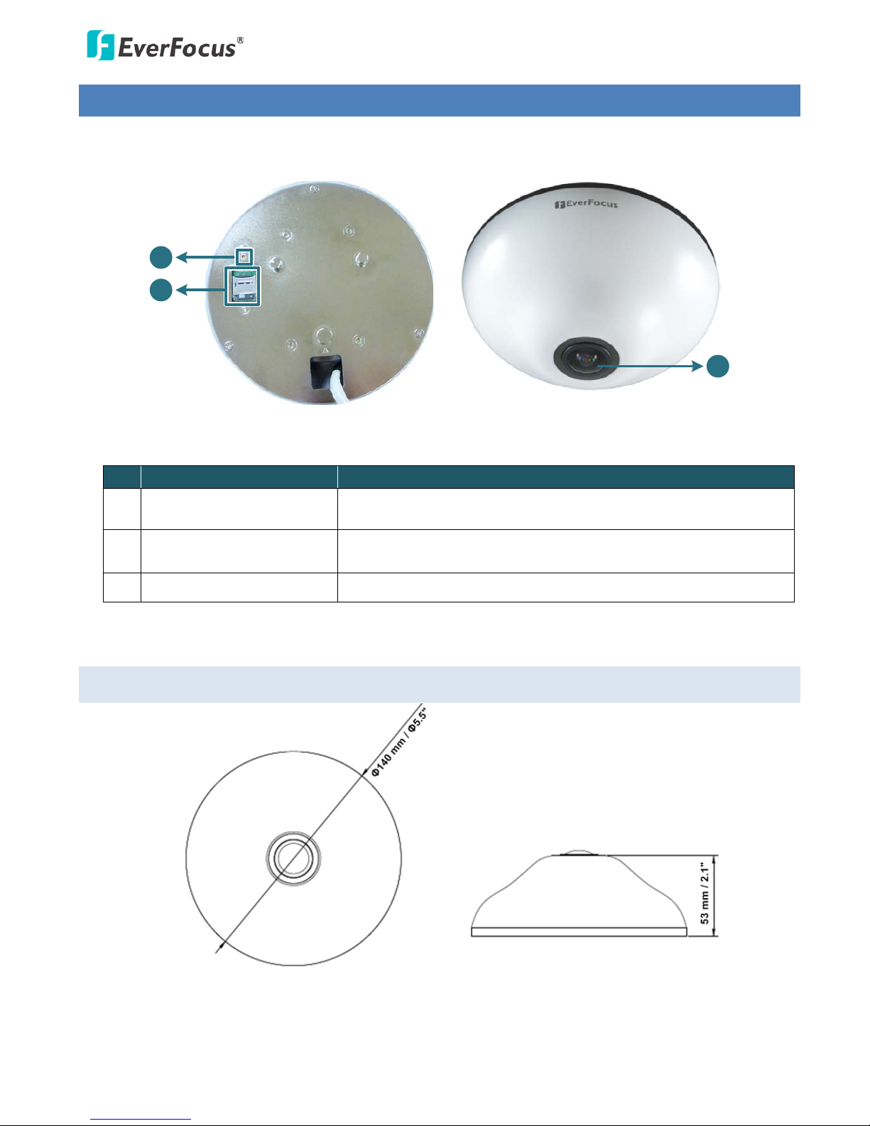
2. Physical Description
2
1
3
Rear View
Front View
No. Item Name Descriptions
1 Reset Button
Press the button for 7 seconds to reset all configurations to the
factory default settings.
2 Micro SDHC / SDXC Slot
For inserting a micro SDHC / SDXC card (see Appendix for the tested
card brands).
3 Fisheye Lens Fisheye lens with fixed IRIS and IR corrected.
2.1 Dimensions
EFN3320 Fisheye Camera
4
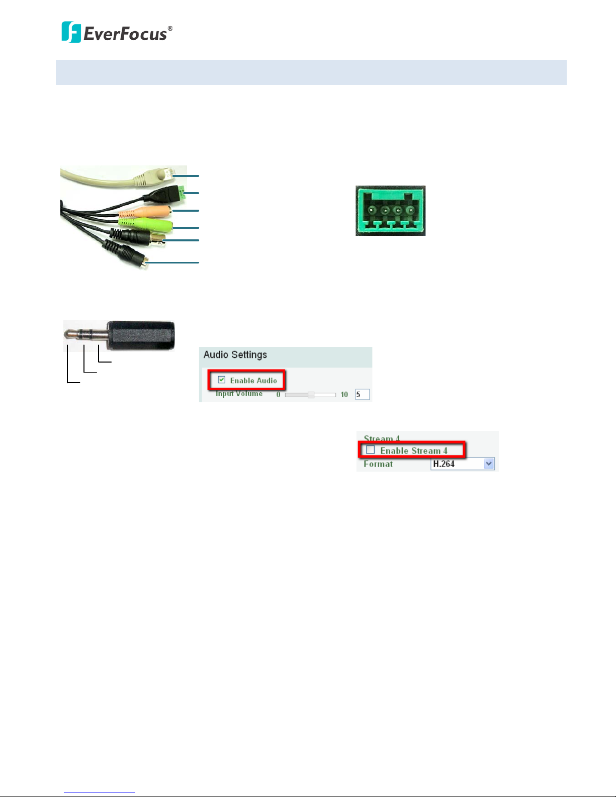
2.2 Cables (BNC, 12 VDC, Audio I/O and Alarm I/O cables are optional)
The Cables provide connections for Network, power, audio input / output, alarm input / output and video
test output. Note that the audio line in/out cable features a 3.5mm TRS connector. Be sure to prepare
speakers / microphones with TRS connector (see TRS Connector image below). Also, speakers / microphones
with a (built-in) amplifier and external power supply are required.
Alarm Input / Output
Audio Input (TRS Line-in)(Pink)
Audio Output (TRS Line-out)(Green)
Video Test-Out (BNC)
12 VDC Input
LAN / PoE Cable
4 3 2 1
Pin Assignment from Alarm I/O
Pin 1: Alarm In (+)
Pin 2: Alarm GND (-)
Pin 3: Alarm COM (-)
Pin 3: Alarm Out (+)
TRS Connector
Left Channel (Tip)
Right Channel (Ring)
Ground (Sleeve)
To activate the Audio function, the Enable Audio must be checked. See
Audio Settings in 7.2.1 Streaming and Audio in the User’s Manual.
For the Video Test-Out cable to work, the Stream 4 must be
disabled (unchecked), see Stream Settings in 7.2.1 Streaming
and Audio in the User’s Manual.
EFN3320 Fisheye Camera
5
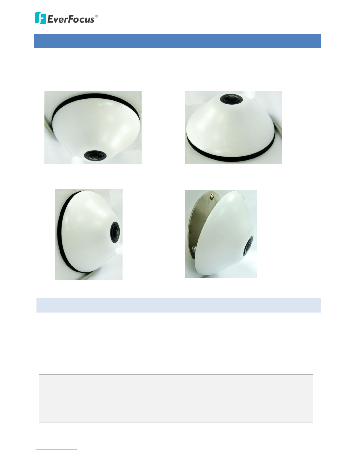
3. Installation
This fisheye camera is designed to be mounted on the ceiling, desk or wall. There are two ways to mount
the camera to the wall: using the supplied Base Plate or the Tilting Wall Mount Bracket.
Ceiling Mount Desk Mount
Wall Mount
With Base Plate
Wall Mount
With Tilting Wall Mount Bracket
3.1 Packing List
Please check that there is no missing item in the package before installing.
• Camera x 1 • Screw x 3 (with 3 Anchors)
• RJ-45 Connector x 1 • Spacer x 1
• Mounting Template x 1 • Software CD x 1
• Tilting Wall Mount Bracket (15° tilt angle) x 1
• Quick Installation Guide x 1
Note:
1. Equipment configurations and supplied accessories vary by country. Please consult your local
EverFocus office or agents for more information. Please also keep the shipping carton for possible
future use.
2. Contact the shipper if any items appear to have been damaged in the shipping process.
EFN3320 Fisheye Camera
6
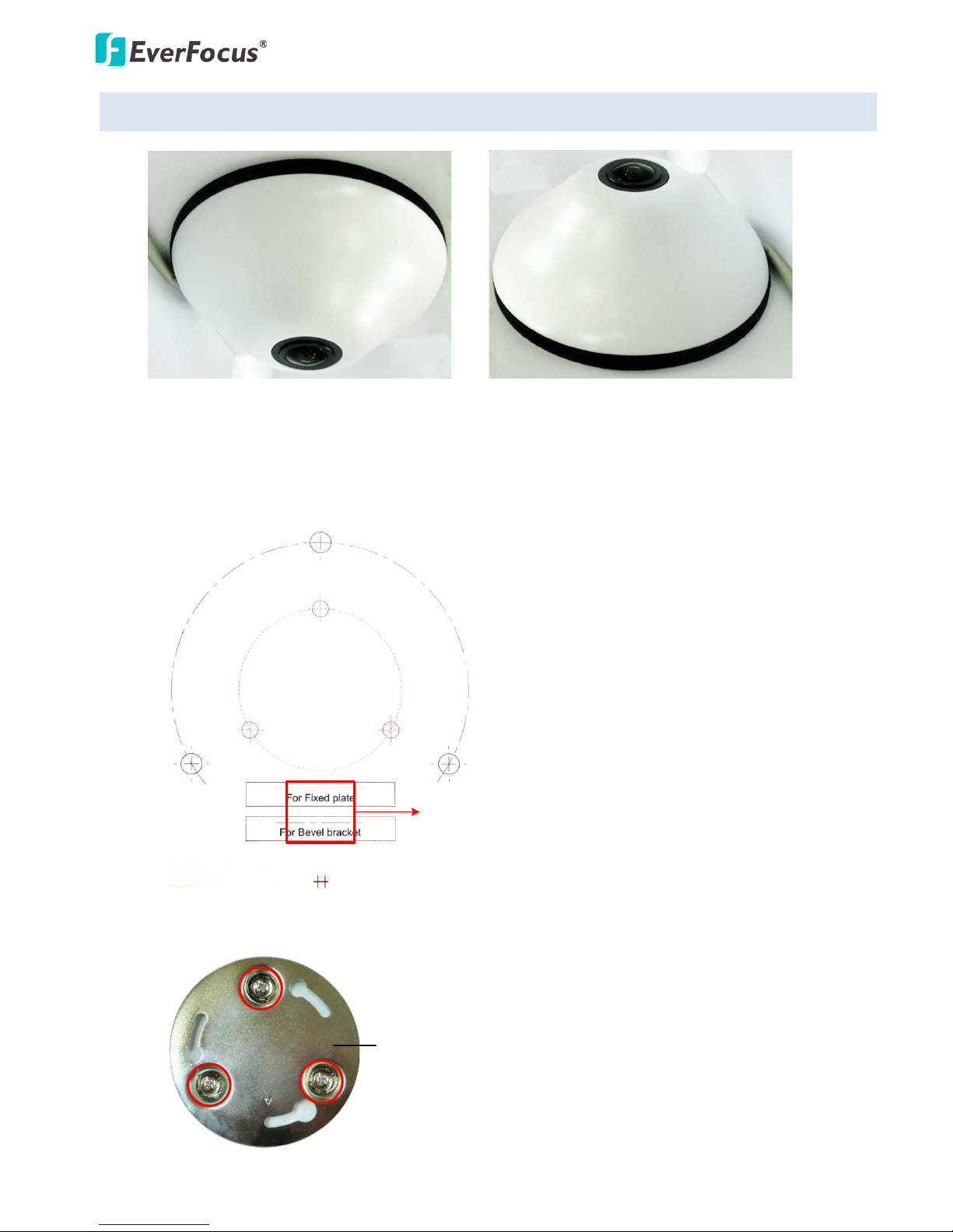
3.2 Ceiling / Desk Mount
Ceiling Mount Desk Mount
1. Stick the Mounting Template to the ceiling / desk. Drill the three red cross marks on the inner
circle, and the square below only if you wish to run the cables through the ceiling / desk. Note that
the square below also indicates the cable position. Point the square below to the direction for
running the cables.
For the Tilting Wall Mount Bracket
Drill a hole only if you want to run
the cables through the ceiling / desk.
2. Insert the supplied three Anchors into the three holes and then screw the Base Plate to the ceiling
/ desk using the supplied three Screws.
Base Plate
EFN3320 Fisheye Camera
7
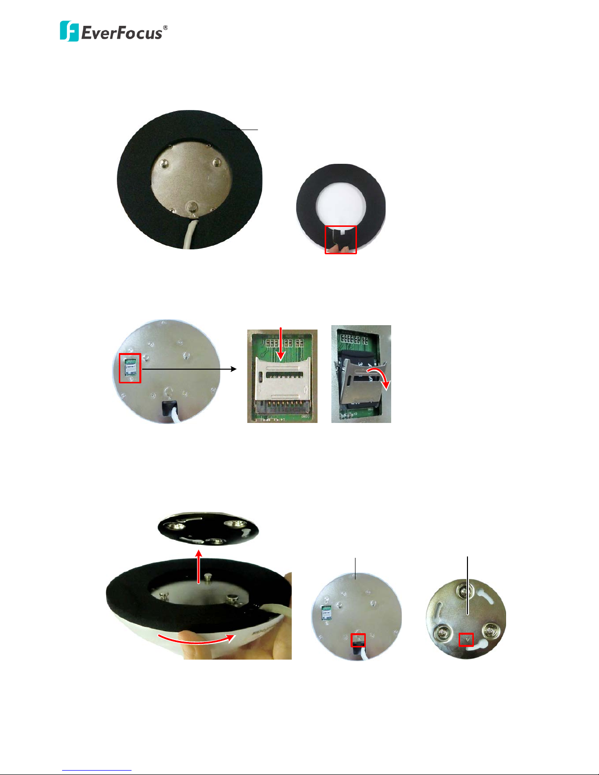
3. Place the Spacer onto the rear side of the camera. Remove the cut-out from the Spacer only if you
want to run the cables along the ceiling / desk.
Spacer
4. Optionally insert the micro SDHC / SDXC card to the push-pull type SD card slot on the rear side of the
camera. For the tested card brands, please refer to Appendix.
Push
Pull
Rear side of the camera
5. Align the three latches on the camera with the three holes on the Base Plate, attach the camera to
the Base Plate and then rotate clockwise to secure the camera to the Base Plate. Note that the
triangle mark on the rear side of the camera and the Base Plate should point to the same
direction.
Rear side of the camera
Base Plate
6. Connect the network or power cable to the camera. The installation is now complete.
EFN3320 Fisheye Camera
8
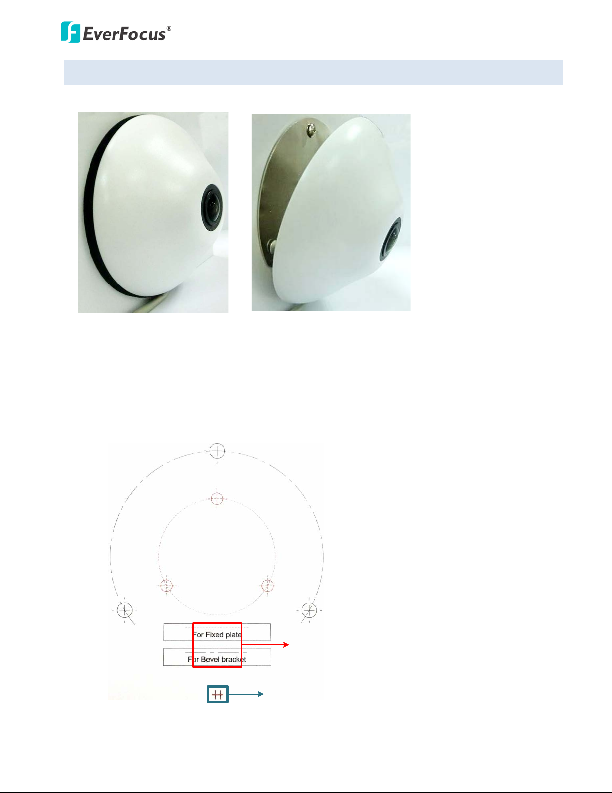
3.3 Wall-Mount
You can mount the camera to the wall using the supplied Base Plate or the Tilting Wall Mount Bracket.
With the Tilting Wall Mount Bracket
With the Base Plate
1. Stick the Mounting Template to the wall. Drill the three red cross marks on the inner circle. If you
want to use the supplied Tilting Wall Mount Bracket, drill the three black cross marks on the outer
circle. Drill the square below only if you wish to run the cables through the wall. Note that the
square below also indicates the cable position. Point the square below to the direction for running
the cables.
Drill a hole only if you want to
run the cables through the wall.
Toward the ground
For the Tilting Wall Mount Bracket
EFN3320 Fisheye Camera
9
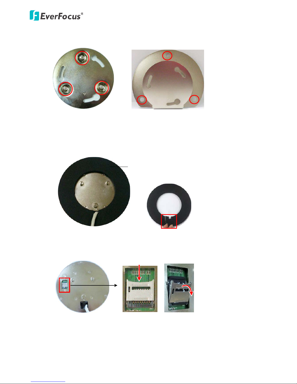
2. Insert the supplied three Anchors into the three holes and then screw the Base Plate / Tilting Wall
Mount Bracket to the wall using the supplied three Screws.
Base Plate
Tilting Wall Mount Bracket
3. If you are using the Base Plate, place the Spacer onto the rear side of the camera. This step is only
for the Base Plate mounting. Remove the cut-out from the Spacer only if you want to run the
cables along the wall.
Spacer
4. Optionally insert the micro SDHC / SDXC card to the push-pull type SD card slot on the rear side of the
camera. For the tested card brands, please refer to Appendix.
Push
Pull
Rear side of the camera
EFN3320 Fisheye Camera
10
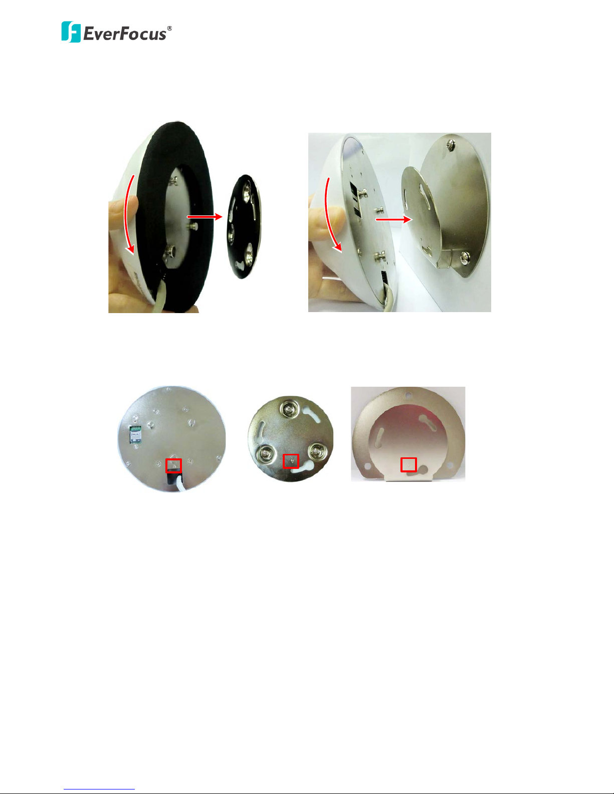
5. Align the three latches on the camera with the three holes on the Base Plate / Tilting Wall Mount
Bracket, attach the camera to the Base Plate / Tilting Wall Mount Bracket and then rotate
clockwise to secure the camera to the Base Plate / Tilting Wall Mount Bracket.
With Base Plate With Tilting Wall Mount Bracket
Note that the triangle mark on the rear side of the camera should point to the same direction with
the triangle mark on the Base Plate / Tilting Wall Mount Bracket.
Rear side of the camera
Base Plate
Tilting Wall Mount Bracket
6. Connect the network or power cable to the camera. The installation is now complete.
EFN3320 Fisheye Camera
11
4. Accessing the User Interface
This section explains how to access the Web interface of the camera for configuration.
4.1 Checking the Dynamic IP Address
You can look up the IP address and access the Web interface of the camera using the IP Utility (IPU)
software included in the software CD. Please connect the IP camera in the same LAN of your computer.
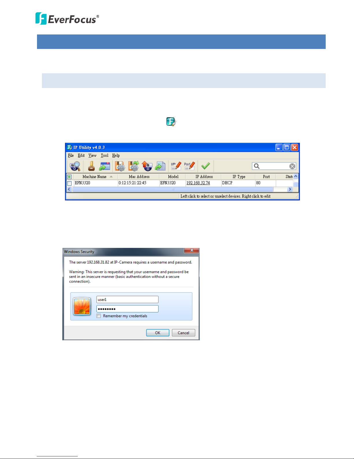
1. Install and then start the IPU program , the following IPU window appears. The IPU will
automatically search the IP devices connected in the LAN.
2. Double click the IP address of the desired device, the login window pops up. Type the user ID and
password to log in. By default, the user ID is user1 or admin and the password is 11111111.
EFN3320 Fisheye Camera
12
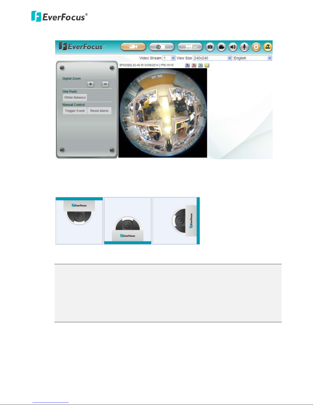
3. Click OK, the Live View window appears.
Note that for the first time user, you will be prompted to choose a desired mounting type of your
fisheye camera. Click to select a mounting type, the above live view window appears. To change
the mounting type, please refer to 7.2.4 Mount.
Note:
1. You might be required to install some add-ons for viewing the camera feed. If asked, click
Run Add-on.
2. To enable Remote Live View, Firmware Upgrade and ActiveX Prompt on Internet Explorer,
some settings have to be complete. Please refer to 4.2 Settings for Microsoft Internet
Explorer in the User’s Manual.
EFN3320 Fisheye Camera
13
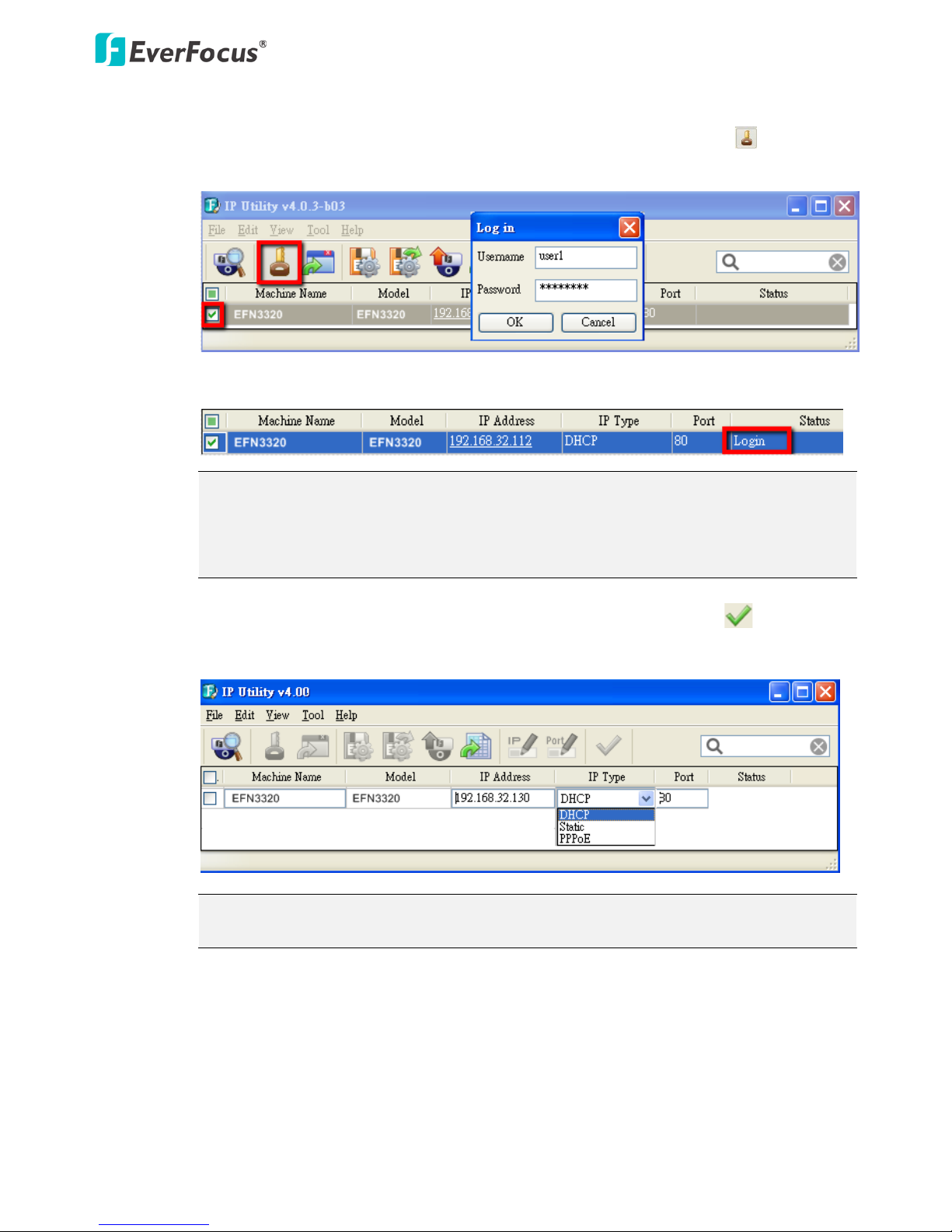
4. To optionally configure the Machine Name, IP Address, IP Type or Port Number using the IPU:
a. Log in the camera by checking the desired model and then click the Log in icon. The Log
in dialog box appears.
b. Type the Username and Password. Click the OK button, the Login status displays.
Note:
1. The default user ID is user1 or admin and the default password is 11111111.
2. If you select more than one camera that has the same user ID / password, you will
be able to log in several cameras at once.
c. Right click the column to configure the settings. Click the Apply Changes button to
apply and save the settings.
Note: Most networks uses DHCP to assign IP address, if you are unsure of your network
settings, please consult your network administrators for configuration details.
EFN3320 Fisheye Camera
14
4.2 Settings for Microsoft Internet Explorer
A. To enable Remote Live View, Firmware Upgrade and ActiveX Prompt on Internet Explorer, some
settings have to be complete. Please follow the steps below:
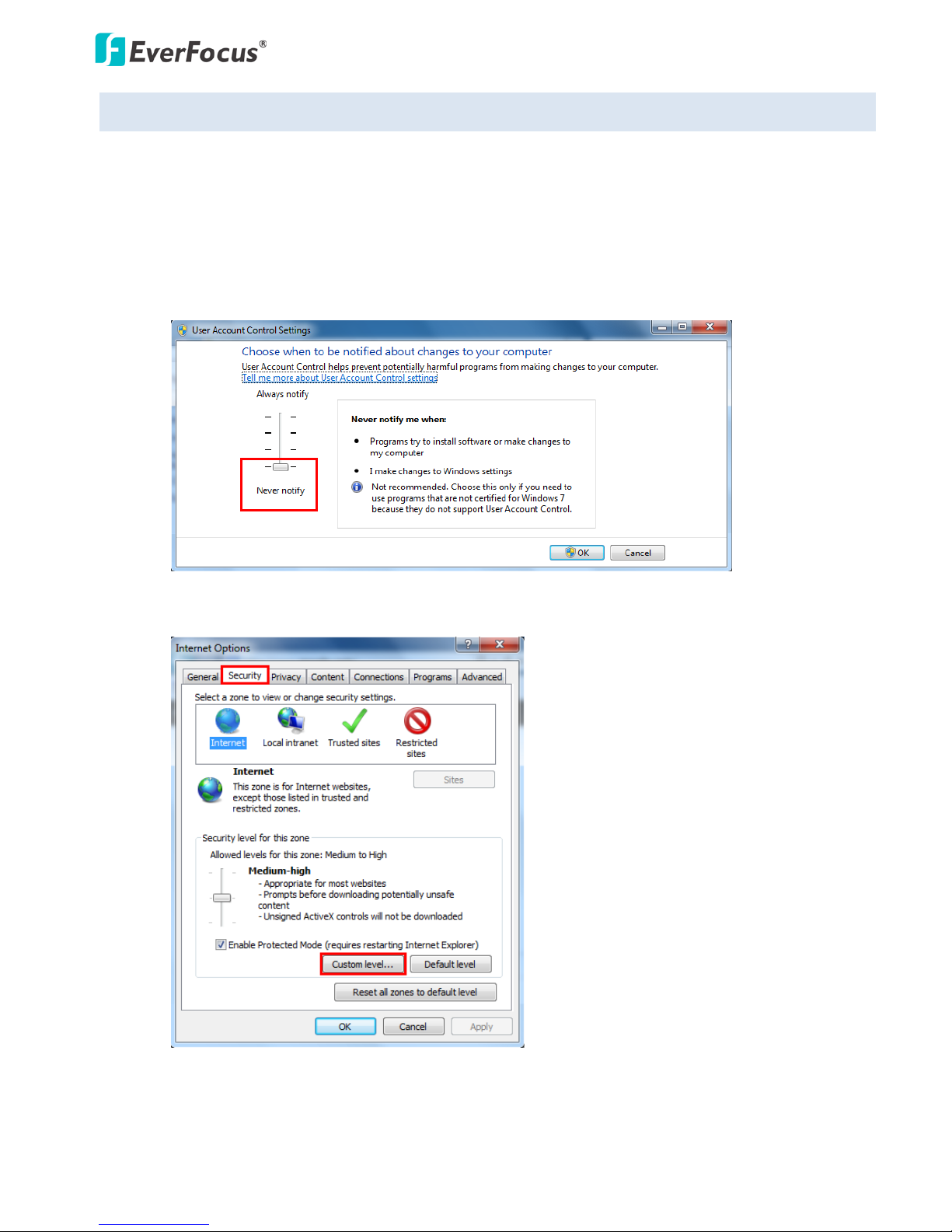
1. On the computer, click Start > Control Panel > System and Security > Action Center (click Change
User Account Control Settings), the User Account Control Settings window appears. Adjust the
slide bar to Never Notify and then click OK. Restart your computer if requested.
2. Open the Internet Explore, click Tools > Internet Options > Security Tab > Custom Level, the
Security Settings windows appears.
EFN3320 Fisheye Camera
15
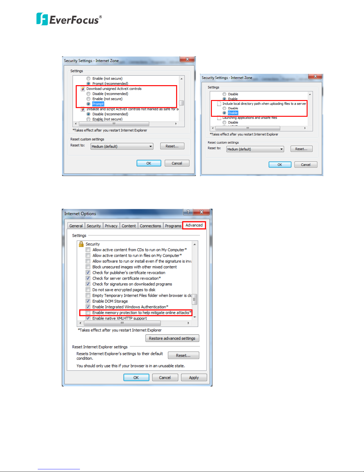
3. In the Download unsigned ActiveX controls field, select Prompt. In the Include local directory
path when uploading files to a server field, select Enable. Click OK.
4. In the Internet Options window, click the Advanced tab and then disable Enable memory
protection to help mitigate online attacks. Click OK.
EFN3320 Fisheye Camera
16
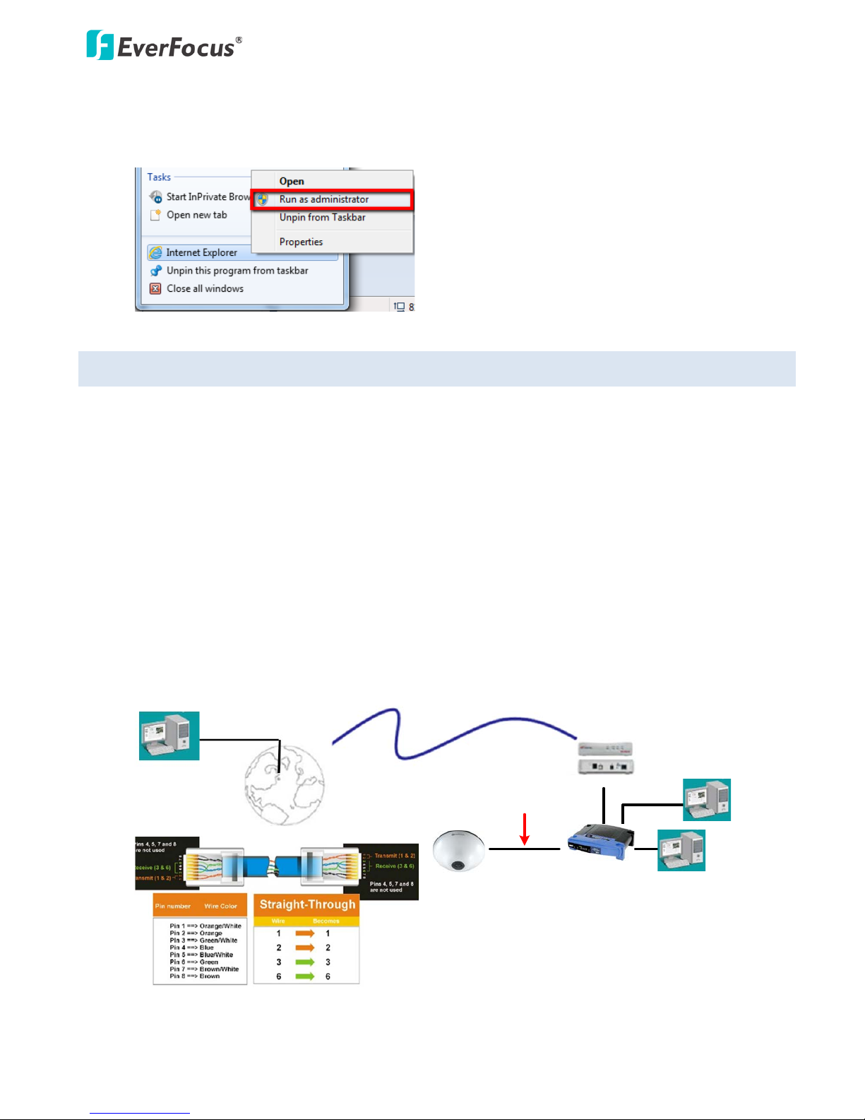
B. For Windows 8 and above systems, to enable the local recording function by clicking the Recording
button on the Live View window, please select “Run as administrator” on the browser.
Right-click on the IE icon and select Run as administrator.
4.3 Connecting the Camera to the Network
There are three methods to connect the IP camera to the network: Router or LAN Connection, Direct
High-Speed Connection and One-to-One Connection.
Router or LAN connection
This is the most common connection in which the IP camera is connected to a router and allows multiple
users on and off site to see the IP camera on a LAN/WAN (Internet). The camera must be assigned an IP
address that is compatible with its LAN. By setting up port forwarding on the router, you can remotely
access the cameras from outside of the LAN via the Internet. To remotely access the Web interface of the
IP camera, please refer to 7.1.1 Network (DDNS Settings). To set up port forwarding, please consult the
manual of the router.
High-speed modem
Internet
Straight-through LAN patch cable
Router
Cat 5 Straight Through Cable
Left: Pinout of a straight-through cable.
EFN3320 Fisheye Camera
17
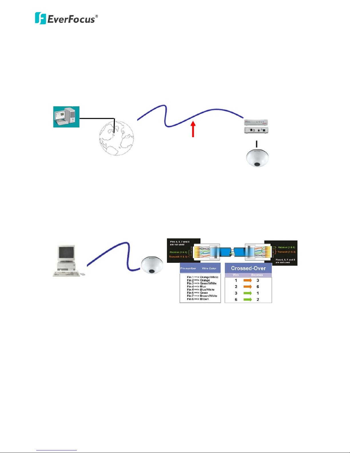
Direct High-Speed Connection
In a Direct High-Speed Connection, the camera connects directly to a modem without the need for a
router. You need to set the static or dynamic WAN IP address assigned by your ISP (Internet Service
Provider) in the camera’s configuration web pages. To access the camera, just type “http://xxx.xxx.xxx.xxx”,
where xxx.xxx.xxx.xxx is the IP address given by your ISP. If you have a dynamic IP address, this connection
may require that you use DDNS for a reliable connection. Please refer to 7.1.1 Network (DDNS Settings).
Cat 5
Straight Through Cable
High-speed modem
Internet
One-to-One Connection (Directly from PC to IP Camera)
You can connect directly without using a switch, router or modem. However, only the PC connected to the
camera will be able to view the IP camera. You will also have to manually assign a compatible IP address to
both the computer and the IP camera. Unless the PC has another network connection, the IP camera will
be the only network device visible to the PC. See the diagram below:
Cat 5
Right: Pinout of a crossed-over cable.
EFN3320 Fisheye Camera
18
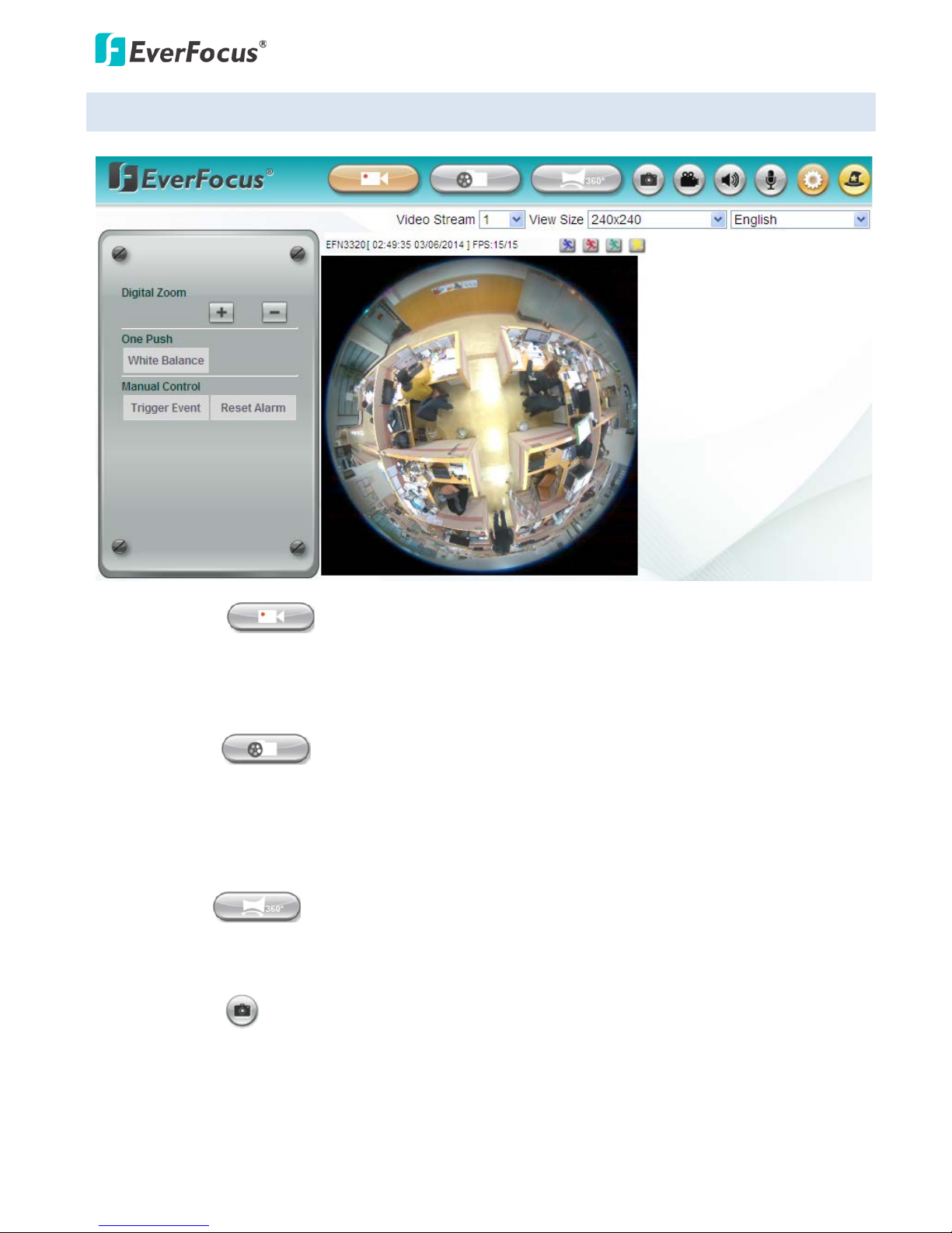
4.4 Live View Window
1. Live View
Click the Live View button to display the Live View window. If you experience video feed lag time (if
connected via Internet), you can reduce the resolution or limit the number of streams. See 7.2.1
Streaming and Audio.
2. Playback
Click the Playback button to play back the recorded data directly from the on-camera SD / SDHC card.
For this function to become active, you have to insert an SD / SDHC card into the SD / SDHC card slot
on the camera (see 5.2 Setting up the Playback Function). For the tested card brands, please refer to
Appendix.
3. Fisheye
Click the Fisheye button to enter the Fisheye setup page. You can configure all the fisheye settings on
this page (see 6. Fisheye Settings).
4. Snapshot
Click the Snapshot button to take a snapshot. By default, the snapshot will be saved at C:\EverFocus\.
To change the location, see Record to Local in 7.1.3 Storage.
Note: For Microsoft IE10 and above users, some settings have to be complete to enable this function
(see B. Snapshot/Record error message in 10. Troubleshooting).

EFN3320 Fisheye Camera
19
5. Record
Click the Record button to start / stop recording the current video stream. By default, this icon is only
for one-minute video recording and the recordings will be saved at C:\EverFocus\. To change the
recording time, see File Size in 7.1.3 Storage. To change the location, see Record to Local in 7.1.3
Storage. To record long-period recordings, please set up a recording schedule (see Schedule Settings
in 7.3.2 Event). To change the source video stream and recording format, see Recording and Snapshot
Settings in 7.1.3 Storage.
Note: For Microsoft IE10 and above users, some settings have to be complete to enable this function
(see B. Snapshot/Record error message in 10. Troubleshooting).
6. Speaker / Microphone
These buttons are only appeared if your camera features the audio cables. Click the Speaker and
Microphone buttons to switch the sound on/off for the speakers and microphones respectively. To
enable the icons, the speakers or microphones should be connected to the camera directly or via the
network. To activate the Audio function, the Enable Audio must be selected. See Audio Settings in
7.2.1 Streaming and Audio. Note that the camera provides a line in/out 3.5mm jack (TRS), therefore,
speakers / microphones with a (built-in) amplifier and external power supply are required.
7. Setting
Click the Setting button to enter the Settings page (see 7. General Settings).
8. Wizard
Click the Wizard button to enter the Setup Wizard.
9. Video Stream
Select the Video Stream (Stream 1, Stream 2, Stream 3 or Stream 4) that will be displayed in the live
view window. Stream 2, Stream 3 and Stream 4 are only selectable if you have enabled the stream
(see 7.2.1 Streaming and Audio). The default setting is Stream 1 only.
10. View Size
Use this to select the appropriate view size and shape of the video on the live view window. A smaller
size might increase transmission speed and video quality.
11. Language
Click the Language drop-down list to select the desired language.
12. Digital Zoom
Click to zoom in / out the camera view up to 10x. Clicking on a magnified image will re-center
the image around that point.
EFN3320 Fisheye Camera
20
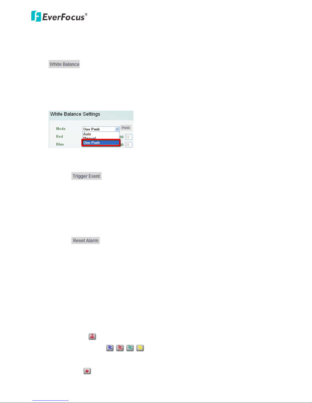
13. One Push
The One Push button can be displayed on the live view window by enabling the Show One Push
Buttons function in the Live View Layout Settings (see 7.1.4 Display and Overlay). For the
button to work, select One Push from the White Balance Mode drop-down list (see
7.2.6 Image). Once this is done, clicking the White Balance button on the Live View Window will
instruct the camera to adjust the white balance settings, and these settings will be active until the
button is pushed again. This is like a “semi-automatic” way to adjust white balance to suit the user, if
the Auto or Manual mode does not give the result the user wants.
14. Manual Control
Click the button to trigger an event directly from the Live View window. If you have
configured an event (in the Event List) that will trigger a reaction (like a recording) when a Manual
Trigger event occurs, clicking this button will trigger that reaction. You can select what that reaction
will be. You can, for instance, set the camera to record the audio/video feed to the SD card on board
the camera. You can then click on the Playback button to open the Playback page and search for and
play all such recordings that had been stored on the card. Such event actions will be effective once
they have been configured in the Event List (see 7.3.2 Event).
Click the button to reset the alarm output remotely. This button is only available if the
camera features the alarm I/O cable.
15. Status Display (info line that can be placed above video box or at bottom of page)
This shows the name of the camera that is currently active or being configured, current date/time
and current frame rate. You can activate these info displays in the Overlay Text Settings (see 7.1.4
Display and Overlay).
16. Event signal icons (above video screen)
When an alarm or motion event is triggered, a signal icon will appear at the top right of the Live View
window to alert the user.
Alarm event icon : When an alarm is triggered, this icon appears.
Motion detection icons : The colors of these motion event icons correspond to the
colors of the motion trigger areas you have configured in the Motion Settings (see 7.3.2 Event).
Recording icon : When the camera is recording to a PC-based folder, this icon appears.
EFN3320 Fisheye Camera
21
5. Playback
You can remotely play back the recordings stored in the on-camera SD card on the Web interface, or play
back the recordings stored in the computer using the ARV Viewer included in the software CD.
Playback is designed as a quick way to check recent recordings that were triggered by Events that were
configured to “Record to SD Card” in the Event Management (see 7.3.2 Event).
Note: The Playback page is only accessible once the on-camera SD card is inserted and active. Please
refer to Appendix for the tested card brands.
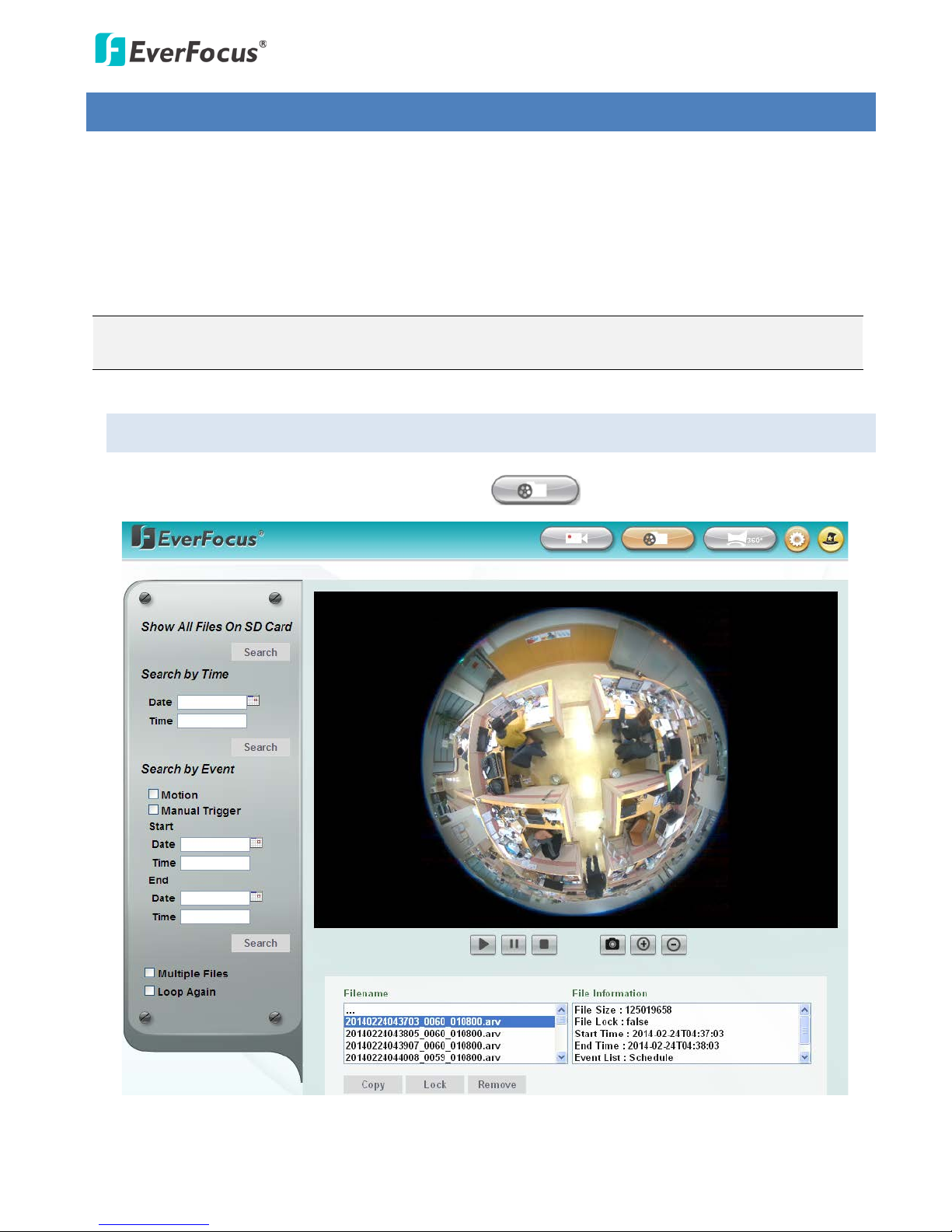
5.1 Remote Playback Using Playback Page
On the Live View Window, click the Playback button to enter the Playback page.

EFN3320 Fisheye Camera
22
Search by File: Click the Search button to search for all recording files on the on-camera SD card.
Search results will be displayed in the Filename area.
Search by Time: Click the Date / Time column and select the date and time from which you want to
search until the present moment. Click Search to get your search results, which will be displayed in
the Filename area.
Search by Event: Select the type of Event recordings you want to search for (Alarm, Motion, Manual
Trigger) and then click the Start Date / Time; End Date / Time column to select the Start Time
date/time and the End Time date/time of your search. Click Search to get your search results, which
will be displayed in the Filename area.
Multiple Files: Check this box if you want the video player to play all the files in the selected folder.
The files will be displayed in the Filename area.
Loop Again: Check this box if you want the video player to play the selected file over and over again.
Play: Once you have opened the file’s folder and have clicked on the file to highlight it, its details will
be displayed in the File Information area. You can now click Play to play that specific file.
Pause: Click to pause playing back.
Stop: Click to stop playing back.
Snapshot: Click to take a snapshot.
Zoom In: Click to zoom in.
Zoom Out: Click to zoom out.
Filename: This area will display a list of search results (recording files and folders). Folders (named
with the recorded date) will be displayed first. Click on the folder and click on each subfolder until the
recording files (.arv) in that folder is listed.
File Information: Click a file on the Filename list, the selected file information will be listed.
Copy: Click to copy the selected file to the computer-based folder of your choice. A browsing box will
open so that you can search for the folder of your choice. You can use the ARV Viewer to play back
the recordings recorded in your computer. For details on ARV Viewer, see 5.3 Playing Back Using ARV
Viewer.
Lock: Click to lock the selected file. This will protect that file from being overwritten during any
overwrite procedure. The file will thus be saved on the micro SD card indefinitely. However, the file
will still be deleted if the micro SD card is ever formatted.
Remove: Click to delete the selected file.
 Loading...