

Page 1
Sentinel System
ESN41 Ultra Compact 4CH H.264 Video Recorder
User’s Manual
Copyright © EverFocus Electronics Corp.
Release Date: April, 2017
Page 2

E V E RFOCUS E LE C T RO N I C S C O R P OR A T I O N
Sentinel System
ESN41 / ESN41-E Ultra Compact 4CH H.264 Video Recorder
User’s Manual
1995‐2017 EverFocus Electronics Corp.
www.everfocus.com.tw
Disclaimer
All the images including product pictures or screen shots in this document are for example only. The
images may vary depending on the product and software version. Information contained in this document
is subject to change without notice.
Copyright
All rights reserved. No part of the contents of this manual may be reproduced or transmitted in any form
or by any means without written permission of the EverFocus Electronics Corporation.
Windows is a registered trademark of the Microsoft Corporation.
Linksys is a registered trademark of the Linksys Corporation.
D‐Link is a registered trademark of the D‐Link Corporation.
DynDNS is a registered trademark of the DynDNS.org Corporation.
Other product and company names mentioned herein may be the trademarks of their respective owners.
Page 3

Safety Precautions
Refer all work related to the installation of this product to qualified service personnel or
system installers.
Do not block the ventilation openings or slots on the cover.
Do not drop metallic parts through slots. This could permanently damage the appliance.
Turn the power off immediately and contact qualified service personnel for service.
Do not attempt to disassemble the appliance. To prevent electric shock, do not remove
screws or covers. There are no user‐serviceable parts inside. Contact qualified service
personnel for maintenance. Handle the appliance with care. Do not strike or shake, as this
may damage the appliance.
Do not expose the appliance to water or moisture, nor try to operate it in wet areas. Do
take immediate action if the appliance becomes wet. Turn the power off and refer servicing
to qualified service personnel. Moisture may damage the appliance and also may cause
electric shock.
Do not use strong or abrasive detergents when cleaning the appliance body. Use a dry cloth
to clean the appliance when it is dirty. When the dirt is hard to remove, use a mild
detergent and wipe gently.
Do not overload outlets and extension cords as this may result in a risk of fire or electric
shock.
Do not operate the appliance beyond its specified temperature, humidity or power source
ratings. Do not use the appliance in an extreme environment where high temperature or
high humidity exists. Use the system at temperatures within ‐40°C~55°C / ‐40°F~131°F
(Storage). The input power source is 12VDC.
Read Instructions
All the safety and operating instructions should be read before the unit is operated.
Retain Instructions
The safety and operating instructions should be retained for future reference.
Heed Warnings
All warnings on the unit and in the operating instructions should be adhered to.
ii
Page 4

ATTENTION! This is a class A product which may cause radio interference in a domestic
Follow Instructions
All operating and use instructions should be followed.
Cleaning
Unplug the unit from the outlet before cleaning. Do not use liquid cleaners, abrasive or
aerosol cleaners. Use a damp cloth for cleaning.
Attachments
Do not use attachments not recommended by the product manufacturer as they may
cause hazards.
Water and Moisture
Do not use this unit near water‐for example, near a bath tub, wash bowl, kitchen sink, or
laundry tub, in a wet basement, near a swimming pool, in an unprotected outdoor
installation, or any area which is classified as a wet location.
Servicing
Do not attempt to service this unit by yourself as opening or removing covers may expose
you to dangerous voltage or other hazards. Refer all servicing to qualified service
personnel.
Power Cord Protection
Power supply cords should be routed so that they are not likely to be walked on or pinched
by items placed upon or against them, playing particular attention to cords and plugs,
convenience receptacles, and the point where they exit from the appliance.
Object and Liquid Entry
Never push objects of any kind into this unit through openings as they may touch
dangerous voltage points or short‐out parts that could result in a fire or electric shock.
Never spill liquid of any kind on the unit.
RTC (Real Time Clock) Battery
When encounter failure of time calibration of your DVR, the issue may be caused by
running‐out of RTC battery. Users will have to change the RTC battery on the main board
of the System.
environment; in this case, the user may be urged to take adequate measures.
iii
Page 5
This Product is RoHS compliant.
Federal Communication Commission Interference Statement
WEEE
The information in this manual was current upon publication. The manufacturer reserves the right to
This equipment has been tested and found to comply with the limits for a Class B digital
device, pursuant to Part 15 of the FCC Rules. These limits are designed to provide
reasonable protection against harmful interference in a residential installation. This
equipment generates, uses and can radiate radio frequency energy and, if not installed
and used in accordance with the instructions, may cause harmful interference to radio
communications. However, there is no guarantee that interference will not occur in a
particular installation. If this equipment does cause harmful interference to radio or
television reception, which can be determined by turning the equipment off and on, the
user is encouraged to try to correct the interference by one of the following measures:
•Reorient or relocate the receiving antenna.
•Increase the separation between the equipment and receiver.
•Connect the equipment into an outlet on a circuit different from that to which the
receiver is connected.
•Consult the dealer or an experienced radio/TV technician for help.
FCC Caution: Any changes or modifications not expressly approved by the party
responsible for compliance could void the users’ authority to operate this equipment.
revise and improve his products. Therefore, all specifications are subject to change without prior
notice. Manufacturer is not responsible for misprints or typographical errors.
Please read this manual carefully before installing and using this unit. Be sure to keep it handy for
later reference.
Your EverFocus product is designed and manufactured with high quality materials and
components which can be recycled and reused. This symbol means that electrical and
electronic equipment, at their end‐of‐life, should be disposed of separately from your
household waste. Please, dispose of this equipment at your local community waste
collection/recycling centre. In the European Union there are separate collection systems
for used electrical and electronic product.
Please, help us to conserve the environment we live in!
iv
Page 6

TABLE OF CONTENTS
1. Introduction ................................................................................................................... 1
1.1 Features .......................................................................................................................... 2
1.2 eZ. Controller Function Description ................................................................................ 3
1.3 HTTP POST / GET Technology ......................................................................................... 5
1.3.1 HTTP POST ................................................................................................................... 5
1.3.2 HTTP GET ................................................................................................................... 10
1.4 Packing List .................................................................................................................... 11
1.5 Optional Accessories ..................................................................................................... 12
1.6 Front Panel .................................................................................................................... 13
1.7 Rear Panel ..................................................................................................................... 14
2. Installation................................................................................................................... 15
2.1 Mounting ....................................................................................................................... 15
2.2 SD Card Installation ....................................................................................................... 17
2.3 Basic Connection ........................................................................................................... 18
2.3.1 Power Input ............................................................................................................... 19
2.3.2 D‐Sub Cable ............................................................................................................... 19
2.3.3 Monitor Connection .................................................................................................. 20
2.4 Turning On / Off the Power .......................................................................................... 20
2.5 Accessing the System .................................................................................................... 21
2.6 Connecting the System to the Network ....................................................................... 26
2.6.1 Router or LAN Connection ........................................................................................ 26
2.6.2 Direct High‐Speed Connection .................................................................................. 29
2.6.3 One‐to‐One Connection ............................................................................................ 30
3. General Operation ....................................................................................................... 34
3.1 USB Mouse Operation .................................................................................................. 34
3.1.1 How to Select a Channel / Enable Audio Out ........................................................... 34
3.1.2 OSD Root Menu ........................................................................................................ 35
3.1.3 Field Input Options.................................................................................................... 35
3.2 General Operation ........................................................................................................ 37
3.2.1 Login .......................................................................................................................... 37
3.2.2 Forget Your Password ............................................................................................... 38
v
Page 7

3.2.3 Camera Selection ...................................................................................................... 38
3.2.4 Audio Selection ......................................................................................................... 39
4. OSD Root Menu ........................................................................................................... 40
4.1 PTZ ................................................................................................................................. 42
4.1.1 Express Control of PTZ .............................................................................................. 44
4.2 Layout Switching ........................................................................................................... 45
4.3 Channel Switching ......................................................................................................... 45
4.4 Display ........................................................................................................................... 46
4.5 Sequence ....................................................................................................................... 47
4.6 Zoom ............................................................................................................................. 47
4.7 Archiving the Recordings or Log Data to the USB or FTP ............................................. 49
4.8 Logout ........................................................................................................................... 52
4.8.1 Temporarily Logout ................................................................................................... 53
5. Search and Playback..................................................................................................... 55
5.1 Quick Playback .............................................................................................................. 55
5.2 Playback Bar .................................................................................................................. 56
5.3 Searching the Recordings for Playing Back ................................................................... 58
5.3.1 Time Search ............................................................................................................... 58
5.3.2 Event Search ............................................................................................................. 59
5.3.3 Smart Search ............................................................................................................. 60
5.3.4 Snapshot Search ........................................................................................................ 61
5.3.5 POS Search ................................................................................................................ 63
6. System ......................................................................................................................... 65
6.1 Express .......................................................................................................................... 67
6.2 Camera .......................................................................................................................... 69
6.2.1 Basic Setting .............................................................................................................. 69
6.2.1.1 Display Aspect Ratio .................................................................................... 71
6.2.2 Adjust Setting ............................................................................................................ 72
6.2.3 eZ Hopper .................................................................................................................. 73
6.3 Record ........................................................................................................................... 76
6.4 Event ............................................................................................................................. 77
6.4.1 Alarm ......................................................................................................................... 77
6.4.1.1 Connect a Radio Clock to the System .......................................................... 79
vi
Page 8

6.4.2 Video Loss ................................................................................................................. 80
6.4.3 Motion....................................................................................................................... 82
6.4.4 Other ......................................................................................................................... 85
6.5 Storage .......................................................................................................................... 90
6.5.1 Storage ...................................................................................................................... 90
6.5.2 Lock/Format .............................................................................................................. 91
6.6 Display Setting............................................................................................................... 92
6.6.1 Monitor OSD ............................................................................................................. 92
6.6.2 M/T SEQ .................................................................................................................... 94
6.7 Network Settings ........................................................................................................... 95
6.7.1 LAN ............................................................................................................................ 95
6.7.2 Email .......................................................................................................................... 98
6.7.3 DDNS ......................................................................................................................... 99
6.7.4 FTP ........................................................................................................................... 105
6.7.5 Alarm Server ........................................................................................................... 106
6.7.6 Remote/Mobile ....................................................................................................... 107
6.7.7 Network Test ........................................................................................................... 108
6.8 Schedule Setting ......................................................................................................... 109
6.8.1 Express Setup .......................................................................................................... 109
6.8.2 Holidays ................................................................................................................... 110
6.8.3 Schedule .................................................................................................................. 111
6.9 System Setting ............................................................................................................ 114
6.9.1 Date / Time ............................................................................................................. 114
6.9.2 Daylight Saving ........................................................................................................ 116
6.9.3 User Group .............................................................................................................. 117
6.9.4 User Management .................................................................................................. 119
6.9.5 I/O Control .............................................................................................................. 121
6.9.6 EKB200 Setting ........................................................................................................ 122
6.9.7 Miscellaneous ......................................................................................................... 124
6.10 Information ................................................................................................................. 126
6.10.1 System ................................................................................................................. 126
6.10.2 Log ....................................................................................................................... 127
7. Remote Access to the System ..................................................................................... 128
7.1 Accessing the System on the Network ....................................................................... 128
7.2 Remote Live View ....................................................................................................... 132
7.3 Menu Bar..................................................................................................................... 133
7.3.1 Express .................................................................................................................... 134
vii
Page 9

7.3.2 Camera .................................................................................................................... 136
7.3.2.1 Basic Setting ............................................................................................... 136
7.3.2.2 Adjust Setting............................................................................................. 138
7.3.3 Record ..................................................................................................................... 140
7.3.4 Event ....................................................................................................................... 141
7.3.4.1 Alarm ......................................................................................................... 141
7.3.4.2 Video Loss .................................................................................................. 144
7.3.4.3 Motion ....................................................................................................... 146
7.3.4.4 Other .......................................................................................................... 149
7.3.5 Storage .................................................................................................................... 154
7.3.5.1 Storage ....................................................................................................... 154
7.3.5.2 Lock/Format ............................................................................................... 155
7.3.6 Display Setting......................................................................................................... 156
7.3.6.1 Monitor OSD .............................................................................................. 156
7.3.6.2 Monitor Sequence ..................................................................................... 157
7.3.7 Network .................................................................................................................. 158
7.3.7.1 LAN ............................................................................................................. 158
7.3.7.2 Email .......................................................................................................... 161
7.3.7.3 DDNS .......................................................................................................... 162
7.3.7.4 FTP ............................................................................................................. 167
7.3.7.5 Alarm Server .............................................................................................. 168
7.3.7.6 Remote/Mobile ......................................................................................... 169
7.3.8 Schedule .................................................................................................................. 170
7.3.8.1 Express Setup ............................................................................................. 170
7.3.8.2 Holiday ....................................................................................................... 171
7.3.8.3 Schedule .................................................................................................... 172
7.3.9 System Setting ........................................................................................................ 175
7.3.9.1 Date/Time .................................................................................................. 175
7.3.9.2 Daylight Saving .......................................................................................... 177
7.3.9.3 User Group ................................................................................................. 178
7.3.9.4 User Management ..................................................................................... 180
7.3.9.5 I/O Control ................................................................................................. 182
7.3.9.6 EKB200 Setting ........................................................................................... 183
7.3.9.7 Miscellaneous ............................................................................................ 185
7.3.10 Information ......................................................................................................... 186
7.3.10.1 System ..................................................................................................... 186
7.3.10.2 Log ........................................................................................................... 187
7.3.11 Copy .................................................................................................................... 188
7.3.12 Search .................................................................................................................. 191
7.3.12.1 Time Search ............................................................................................. 191
7.3.12.2 Event Search ............................................................................................ 192
viii
Page 10

7.3.12.3 Smart Search ............................................................................................ 194
7.3.12.4 POS Search ............................................................................................... 195
7.3.13 PTZ ....................................................................................................................... 196
8. Specifications ............................................................................................................. 198
9. Troubleshooting ......................................................................................................... 200
Appendix A: Network Overview ......................................................................................... 201
Appendix B: Linksys & D-Link Port Forwarding ................................................................... 205
Appendix C: Timing of Alarm Modes .................................................................................. 209
Appendix D: Express Setup Recording Value Selection Rules .............................................. 212
Appendix E: IR Remote Control .......................................................................................... 214
Appendix F: RTSP URL Syntax............................................................................................. 215
Appendix G: Tested Card Brands ........................................................................................ 218
Appendix H: Recording Backup through EF-Reader............................................................. 219
ix
Page 11
1
Sentinel System – Video Recorder
Chapter
1. Introduction
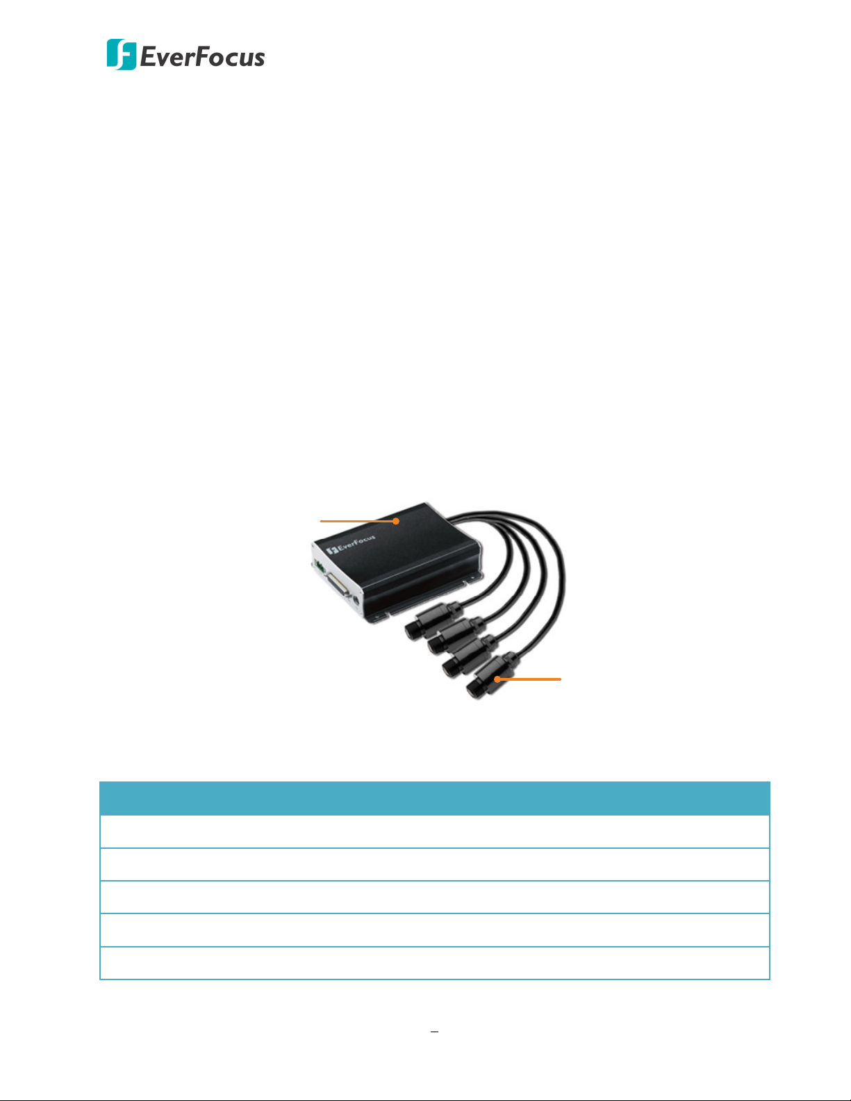
The Sentinel System, bundled with one compact 4CH video recorder and four 1080p FHD cameras,
is ideal for the surveillance environment where areas are closely situated. With Its excellent
compact size, the Sentinel System is perfectly to be widely used no matter in the industrial,
banking or various markets such as ATM, luxury stores, industrial production lines or casino.
As the Sentinel System is bundled with a video recorder and four‐camera, we will introduce the
two products separately. The content in this manual describes the hardware and software of the
4CH recorder. For more details about the cameras, please refer to the User’s Manual of the
Sentinel Camera.
Video Recorder
Camera x 4
The video recorder of Sentinel System comes in two models. Here we listed some differentiation
between the two models.
Spec ESN41 FHD ESN41-E FHD
Channels 4CH mini DIN 4CH mini DIN
Alarm In / Out 4 / 4 ‐
SD Card Slot 2 (max. 128GB per card) 1 (max. 128GB)
RS-485 1 ‐
Power Source PoE / 12VDC 12VDC
1
Page 12
Sentinel System – Video Recorder
1.1 Features
Ultra Compact Size for easy installation
4 channels of Real‐Time 1080p Video and Audio Recording
Recording Rate: up to 30(25)fps/ch @1080p resolution
H.264 format for efficient storage and network utilization
eZ.Controller function: Control camera OSD settings and PTZ operation directly from the
recorder end (see 1.2 eZ. Controller Function Description)
D‐sub Connectors for shock & vibration resistance
Plug‐and‐play recording on the completely shock proof SDHC/SDXC card (up to 128GB per
card)
Archives recordings to the USB storage device
Wide Dynamic Range function (WDR) via Camera OSD
Two‐Way Audio
Easy JPEG Images On‐Demand via HTTP command (HTTP GET, see 1.3 HTTP POST / GET
Technology)
Pop‐up Text / Image on local display via HTTP command (HTTP POST, see 1.3 HTTP POST /
GET Technology)
Water‐resistant design for video input connectors
Video and power transferred through mini DIN cable
Supports multiple interfaces
Double Power Inputs supported: PoE and 12VDC (ESN41 FHD Only)
4 Digital Inputs & 4 Outputs (ESN41 FHD Only)
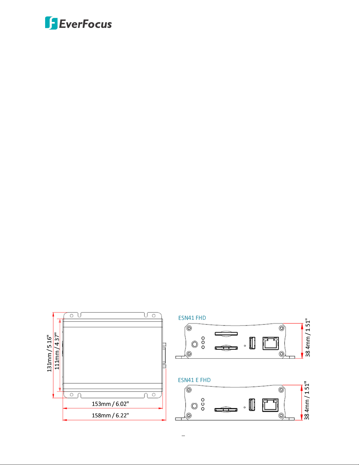
Dimensions
2
Page 13
1.2 eZ. Controller Function Description
Sentinel System – Video Recorder
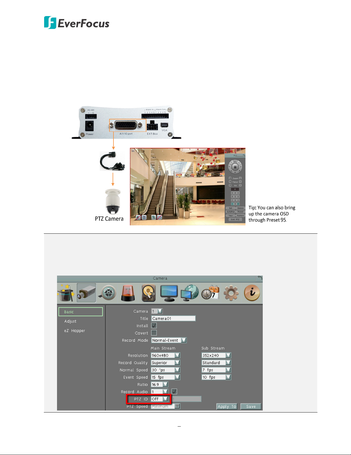
eZ.Controller: Easily control PTZ camera from DVR using only coaxial cable.
This function is currently reserved. eZ.Controller allows users to control PTZ camera from DVR
using only a coaxial cable without the need of a RS‐485 cable between the PTZ camera and the
DVR. Users can easily operate Zoom, Focus, Iris, Direction, Auto Pan, Preset, Tour and Pattern
functions to the PTZ camera through DVR.
Note:
1. The eZ.Controller function for PTZ control is only supported for EverFocus AHD (1080p,
720p) PTZ cameras.
2. After connecting the PTZ camera to the DVR through the coaxial cable, you will have to go
to the OSD Menu to turn the PTZ ID function off (System < Camera < Basic).
3
Page 14
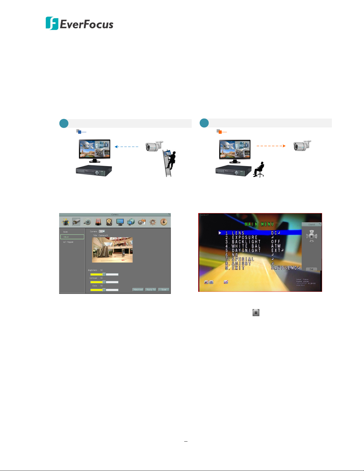
eZ.Controller: Easily control eZ.HD camera’s OSD at the DVR end.
Sentinel System – Video Recorder
Traditionally, the CCTV installer needs to take a portable monitor to connect to the camera
for controlling the camera OSD at the camera installation site as the Diagram A below. It will
take extra effort, time and people to adjust the camera.
Now, EverFocus’ eZ.Controller allows users to control the camera OSD simply on the monitor
at the DVR end as illustrated in Diagram B.
B
A
Traditional Way to Control Camera OSD
Control Camera OSD at Camera End
Use eZ.Controller to Control Camera OSD
Camera OSD Control Directly at DVR End
Camera EndDVR End
How to Control eZ.HD Camera’s OSD at the DVR End?
1. On the DVR’s OSD setting menu, go to
System > Camera > Adjust. Select a
camera you want to adjust.
2. Click the Advanced button, and the
camera live view with the UTC Panel
will be displayed.
1. To display the OSD menu, click the
2. You can use the direction buttons on
3. To exit the camera OSD setting, click
DVR End
Camera End
Enter button on the UTC Panel.
the UTC Panel to control the camera’s
OSD setting menu.
Exit to return to the Adjust setting
page.
4
Page 15
Sentinel System – Video Recorder
1.3 HTTP POST / GET Technology
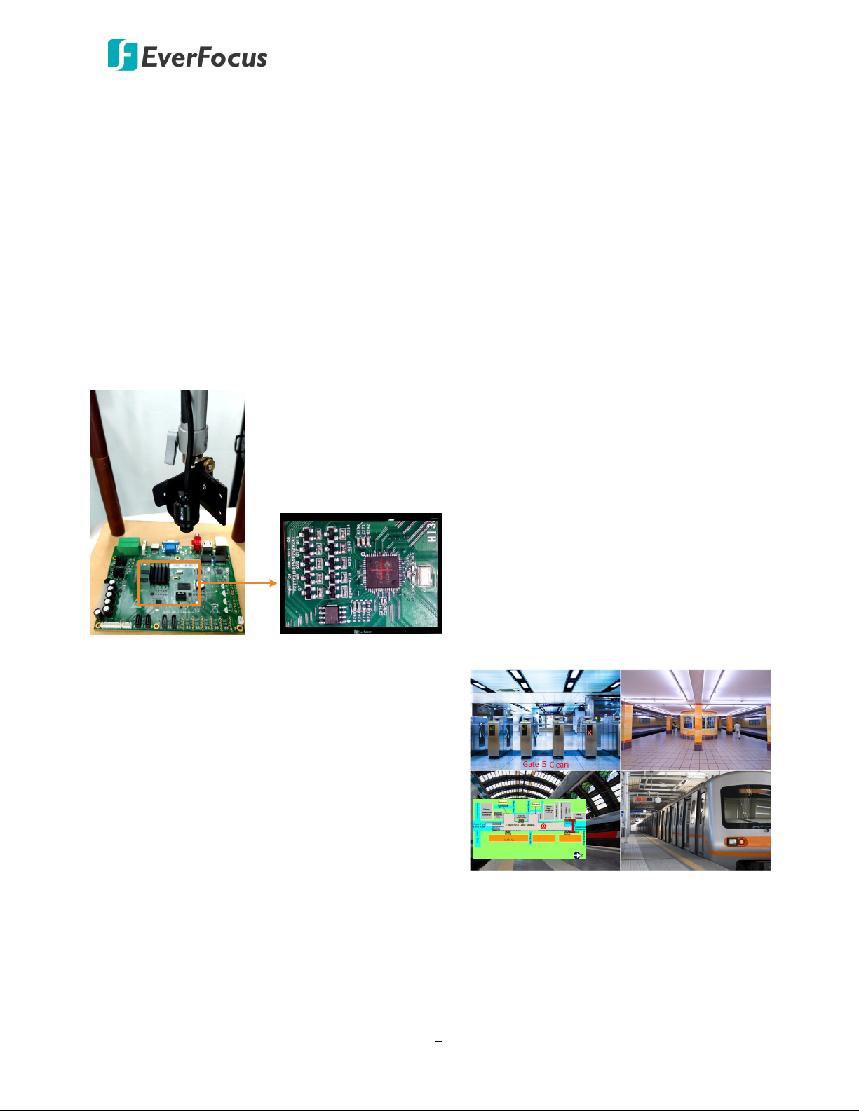
In response to Industry 4.0 that emphasizes on the data exchange in manufacturing technologies,
the Sentinel System is designed with the HTTP POST and HTTP GET technology, allowing data
transmission between a client device and the Sentinel system through CGI command, and then
instantly overlay an image or text on the screen of Sentinel System. The live stream images can
also be captured in 1080p/720p/D1 resolution via a Web browser through CGI command.
1.3.1 HTTP POST
You can utilize the HTTP POST technology to instantly overlay images, texts or marks on the screen
through CGI command.
Cross Mark Overlay through CGI Command
Instant Image/Text Overlay through CGI Command
The HTTP POST technology enables instant images
or text to be displayed on the live screen for
notification. This technology can be remotely done
through CGI commands. You can overlay .bmp
images or texts in any position on the screen or
customize the color of the texts.
Industrial production lines sometimes
require a Cross Mark on the screen for
positioning. Sentinel system allows users to
draw cross marks or squares on the screen
in any position and color.
5
Page 16
Sentinel System – Video Recorder
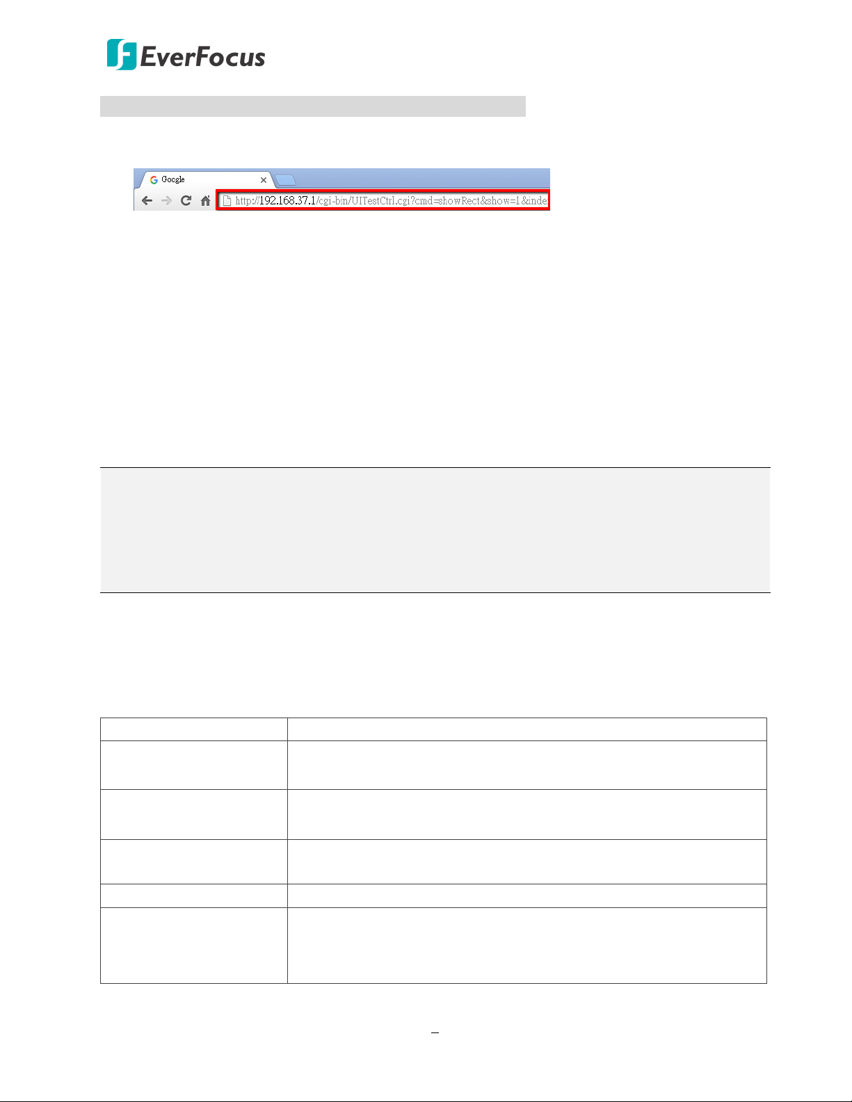
To overlay a cross mark on the screen through CGI command:
1. To overlay a vertical line, open a Web browser and then input the CGI command in the
address field. Please refer to CGI command of vertical/horizontal marks in the below field.
2. Press the Enter key on the keyboard, (login the Sentinel system only for the first‐time use),
the vertical line should be now displayed on the screen.
3. To overlay a horizontal line, open a Web browser and then input the CGI command in the
address field. Please refer to CGI command of vertical/horizontal line marks in the below
field.
4. Press the Enter key on the keyboard, the horizontal line should be now displayed on the
screen.
5. A cross mark should be displayed on the screen.
6. To disable (hide) a line, simply change the “show” value to “0” of the CGI command of a
specific line and then input the CGI command in the address field on the Web browser. Press
the Enter key. Please refer to the Examples in the below field.
Note:
1. A cross mark contains a vertical line and a horizontal line. Users have to input the CGI
commands of the vertical line and horizontal line individually to create a cross mark.
2. Users can also utilize this function to overlay a square mark on the screen by overlaying two
horizontal lines and two vertical lines.
CGI command of vertical/horizontal line marks:
http://[IP address]/cgi‐bin/UICtrl.cgi?cmd=showRect&index=[0~9]&
show=[0,1]&posX=[0~N]&posY=[0~N]&width=[1~N]&height=[1~N]&R=[0~255]&G=[0~255]&B=[0~
255]&A=[0~1]
IP address IP address of the Sentinel system
show
index
posX / posY
0: hide; 1: show
* Input 1 to display the mark; input 0 to hide the mark
0 ~ 9
* Input 0 ~ 9 as the ID of the CGI command (max. 10 commands)
0 ~ N
* Input 0 ~ N to position the mark on the screen
height / width 1 ~ N
R / G / B / A
(red, green, blue, alpha)
R / G / B: 0 ~ 255; A: 0 ~ 1
* Input 0 ~ 255 for RGB color
* A is for transparency: 0 (fully transparent) ; 1 (fully opaque)
6
Page 17
* Input 0 ~ N to position the text on the screen
Sentinel System – Video Recorder
Examples:
Vertical line (show):
http://192.168.37.1/cgi‐bin/UICtrl.cgi?cmd=showRect&index=0&
show=1&posX=960&posY=490&width=1&height=100&R=255&G=0&B=0&A=0
Vertical line (hide):
http://192.168.37.1/cgi‐bin/UICtrl.cgi?cmd=showRect&index=0&show=0
Horizontal line (show):
http://192.168.37.1/cgi‐
bin/UICtrl.cgi?cmd=showRect&index=1&show=1&posX=910&posY=540&width=100&height=1&R=
255&G=0&B=0&A=0
Horizontal line (hide):
http://192.168.37.1/cgi‐bin/UICtrl.cgi?cmd=showRect&index=1&show=0
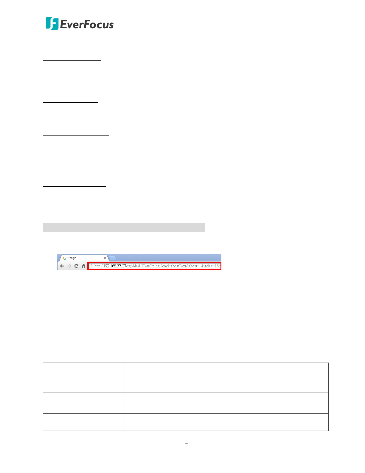
To overlay a text on the screen through CGI command:
1. Open a Web browser and then input the CGI command in the address field. Please refer to
CGI command of text overlay in the below field.
2. Press the Enter key on the keyboard, (login the Sentinel system only for the first‐time use),
the text should be now displayed on the screen.
3. To disable (hide) a text, simply change the “show” value to “0” of the CGI command of a
specific text and then input the CGI command in the address field on the Web browser. Press
the Enter key. Please refer to the Examples in the below field.
CGI command of text overlay:
http://[IP address]/cgi‐bin/UICtrl.cgi?cmd=showText&index=[0~9]&show=[0,1]
&posX=[0~N]&posY=[0~N]&R=[0~255]&G=[0~255]&B=[0~255]&A=[0~1]&String=[XXXXXXX]
IP address IP address of the Sentinel system
show
0: hide; 1: show
* Input 1 to display the text; input 0 to hide the text
index
posX / posY
0 ~ 9
* Input 0 ~ 9 as the ID of the CGI command (max. 10 commands)
0 ~ N
7
Page 18
Sentinel System – Video Recorder
R / G / B / A
(red, green, blue, alpha)
R / G / B: 0 ~ 255; A: 0 ~ 1
* Input 0 ~ 255 for RGB color
* A is for transparency: 0 (fully transparent) ; 1 (fully opaque)
* Input a maximum of 255 characters (alphabetic / numeric)
* Supported characters include : !.,;_‐=+()*^%$@[]{}|/~`
String
* Some special characters, including @’&#<>\ space, are encoding
required. Please encode the characters if you want to include these
characters in a text sentence. You can go to the below website to
encode the characters: http://meyerweb.com/eric/tools/dencoder/
Examples:
Text (show):
http://192.168.37.37/cgi‐
bin/UICtrl.cgi?cmd=showText&index=1&show=1&posX=880&posY=600&R=0&G=255&B=255&A=0
&String=Welcome%20to%20EverFocus!
Text (hide):
http://192.168.37.37/cgi‐bin/UICtrl.cgi?cmd=showText&index=1&show=0
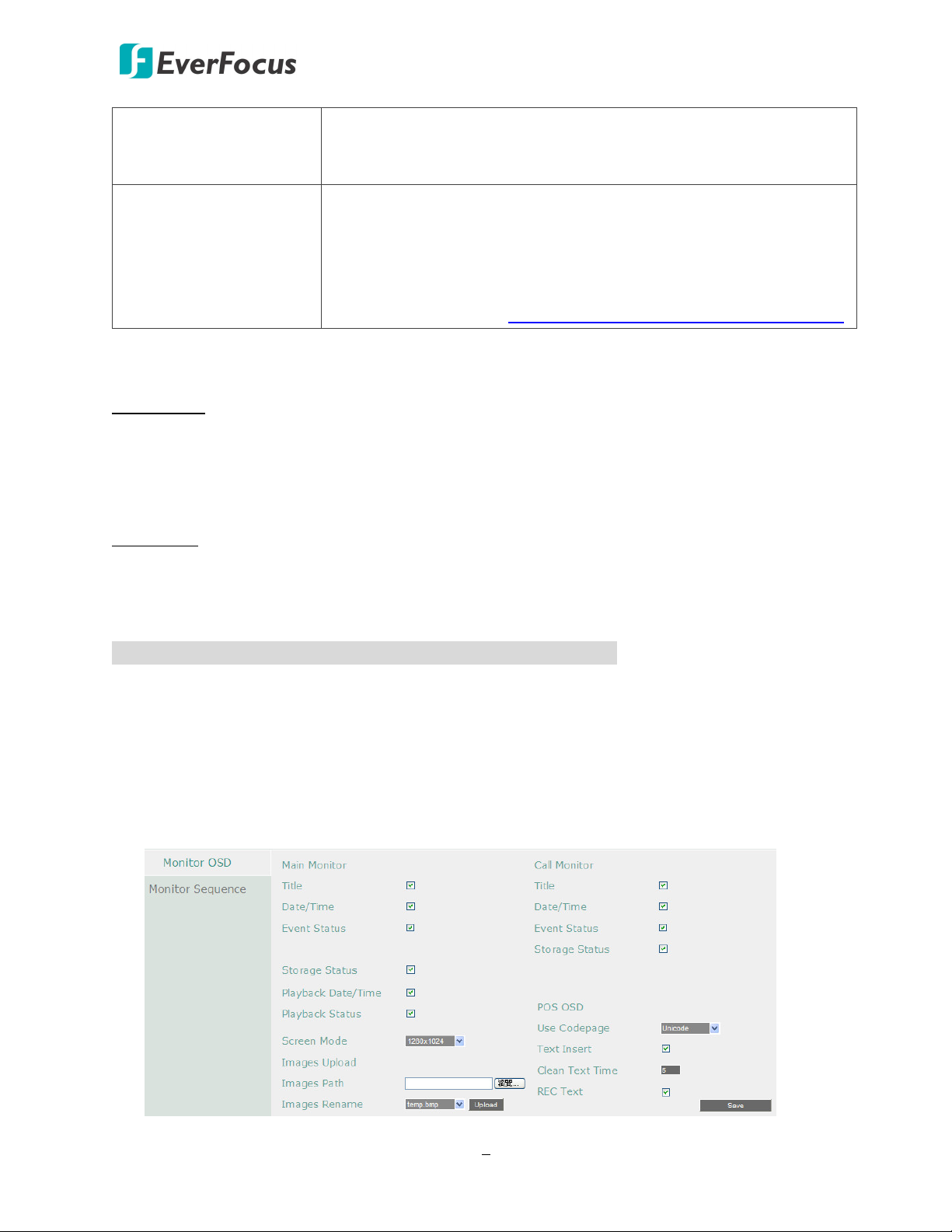
To overlay an image (.bmp) on the screen through CGI command:
1. Prepare an image with 24bit in bmp format (max. size 500kb).
2. Upload the image file to the Sentinel system.
Open the Web UI of the Sentinel system and then go to Display Settings < Monitor OSD. In
the Images Path field, click Browse to select an image from your computer. Select a name
from the Images Rename drop‐down list to apply the name to the selected image. Click
Upload to upload the image. Note that you can upload up to 10 images with the fixed file
names (0 ~ 9).
8
Page 19

Sentinel System – Video Recorder
3. To overlay the uploaded image on the screen:
a. Open a Web browser and then input the CGI command of image overlay in the address
field. Please refer to CGI command of image overlay in the below field.
b. Press the Enter key on the keyboard (login the Sentinel system only for the first‐time use),
the image should be now displayed on the screen.
4. To disable (hide) an image, simply change the “show” value to “0” of the CGI command of a
specific image and then input the CGI command in the address field on the Web browser.
Press the Enter key. Please refer to the Examples in the below field.
CGI command of image overlay:
http://[IP address]/cgi‐bin/UICtrl.cgi? cmd=showImg&index=[0~9]&show=[0,1]
&posX=[0~N]&posY=[0~N]&imgPath=/tmp/[Image File Name]
IP address IP address of the Sentinel system
show
index
posX / posY
Image File Name
0: hide; 1: show
* Input 1 to display the image; input 0 to hide the image
0 ~ 9
* Input 0 ~ 9 as the ID of the CGI command (max. 10 commands)
0 ~ N
* Input 0 ~ N to position the image on the screen
0 ~ 9
* Input an image file name in this field
Examples:
Image1 (show):
http://192.168.37.1/cgi‐
bin/UICtrl.cgi?cmd=showImg&index=0&show=1&posX=0&posY=0&imgPath=/tmp/0
Image2 (show):
http://192.168.37.1/cgi‐
bin/UICtrl.cgi?cmd=showImg&index=1&show=1&posX=500&posY=0&imgPath=/tmp/1
Image3 (show):
http://192.168.37.1/cgi‐
bin/UICtrl.cgi?cmd=showImg&index=2&show=1&posX=0&posY=400&imgPath=/tmp/8
9
Page 20
Sentinel System – Video Recorder
Image1 (hide):
http://192.168.37.1/cgi‐bin/UICtrl.cgi?cmd=showImg&index=0&show=0
Image2 (hide):
http://192.168.37.1/cgi‐bin/UICtrl.cgi?cmd=showImg&index=1&show=0
Image3 (hide):
http://192.168.37.1/cgi‐bin/UICtrl.cgi?cmd=showImg&index=2&show=0
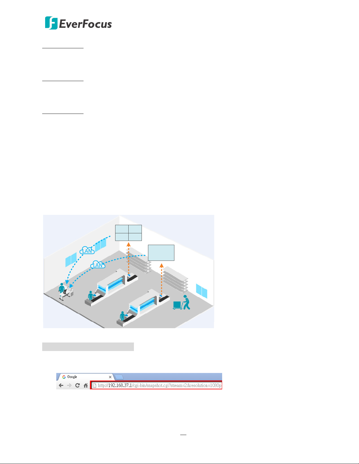
1.3.2 HTTP GET
The HTTP GET technology enables users to remotely capture snapshot images (JPEG) of the live
stream of individual channels in 1080p/720p/D1 resolution from the Sentinel system using the CGI
command.
Live Stream Image Capturing through CGI Command
To capture a live stream image:
1. Open a Web browser and then input the CGI command in the address field. Please refer to
CGI command of live stream image capturing in the below field.
2. Press the Enter key on the keyboard, login the Sentinel system (only for the first‐time use),
the snapshot image should be captured.
10
Page 21
0 ~ 3
Sentinel System – Video Recorder
CGI command of live stream image capturing:
http://[IP address]/cgi‐bin/snapshot.cgi?stream=[stream ID]&resolution=[resolution]
IP address IP address of the Sentinel system
stream ID
* 0 for channel 1, 1 for channel 2, 2 for channel 3, 3 for channel 4
resolution 1080p, 720p, d1
Example: for capturing channel 4 live stream image in 1080p resolution
http://192.168.37.1/cgi‐bin/snapshot.cgi?stream=3&resolution=1080p
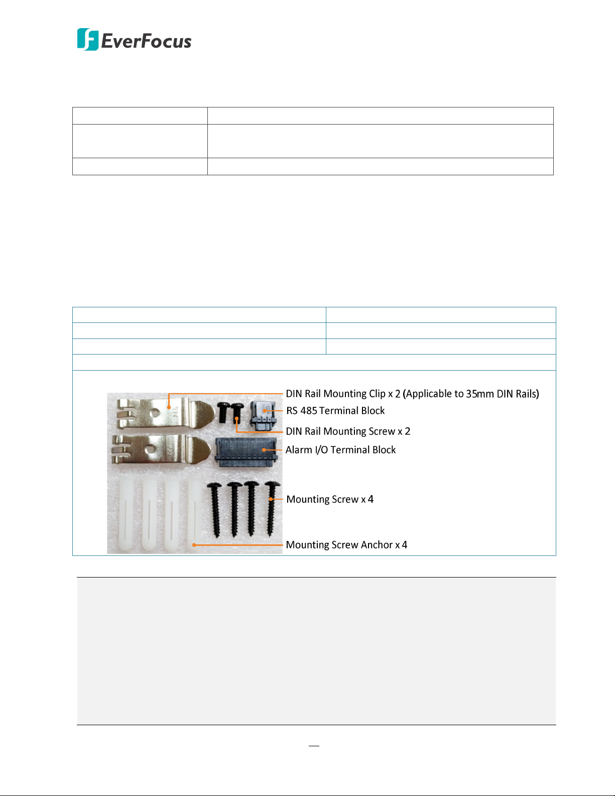
1.4 Packing List
Video Recorder x 1 D‐Sub Cable x 1 (see 2.3.2 D-Sub Cable)
VGA Cable x 1 Quick Installation Guide x 1
Power Adaptor x 1 (see 2.3.1 Power Input) CD x 1 (Please see Note 3.)
IR Remote Control (with two AAA batteries. See Note 4) x 1
Mounting Kit x 1
Note:
1. Equipment configurations and supplied accessories vary by country. Please consult your
local EverFocus office or agents for more information. Please also keep the shipping carton
for possible future use.
2. Contact the shipper if any items appear to have been damaged in the shipping process.
3. The CD contains the IP Utility software, User Manual and Quick Installation Guide.
4. Risk of explosion if battery is replaced by an incorrect type. Dispose of used batteries
according to the instructions.
a. Use only two AAA dry cell batteries.
b. Do not dispose of the batteries in a fire as it may explode.
11
Page 22
1.5 Optional Accessories
Camera
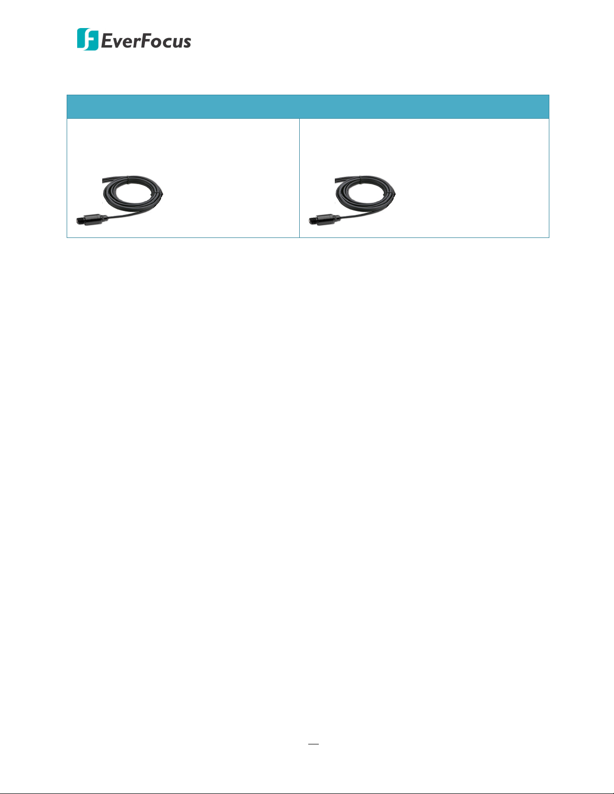
Sentinel System – Video Recorder
S200
Sentinel Camera, 2.7mm, Sony sensor,
1080p, 3m cable, Mini Din
S208
Sentinel Camera, 8mm, Sony sensor, 1080p, 3m
cable, Mini Din, Focus Adjustable, Industrial use
12
Page 23
Sentinel System – Video Recorder
1.6 Front Panel
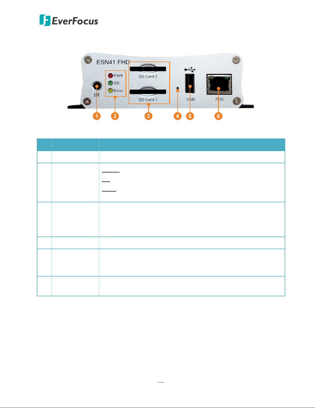
No. Name Description
1 IR Receiver Receives data from the infrared remote control.
Power: Lights red continuously when power is supplied.
2 System LEDs
SD: Lights green continuously when SD card is reading or writing data.
Error: Lights yellow continuously when system error occurs, including
System Clock Error, SD Failed, SD Off and Network Loss.
Insert a SDHC/SDXC card (up to 128GB per card) for recording (see 2.2
3 SD Card Slot
SD Card Installation). To see the SD card info, see 6.5.1 Storage. You
can also see Appendix G for tested card brands. (ESN41‐E FHD only
provides one SD Card Slot)
4 Reset Button Press and hold the Reset Button to restart system.
Connects to a USB storage device or a mouse. You can use the USB
5 USB2.0 Port
storage device for archiving (backup) recordings. Up to 4TB storage
capacity is supported of the USB storage device.
6 LAN / PoE
Connects to a 10/100/1000 Ethernet or PoE switch (ESN41‐E FHD
doesn’t support PoE function).
13
Page 24
1.7 Rear Panel
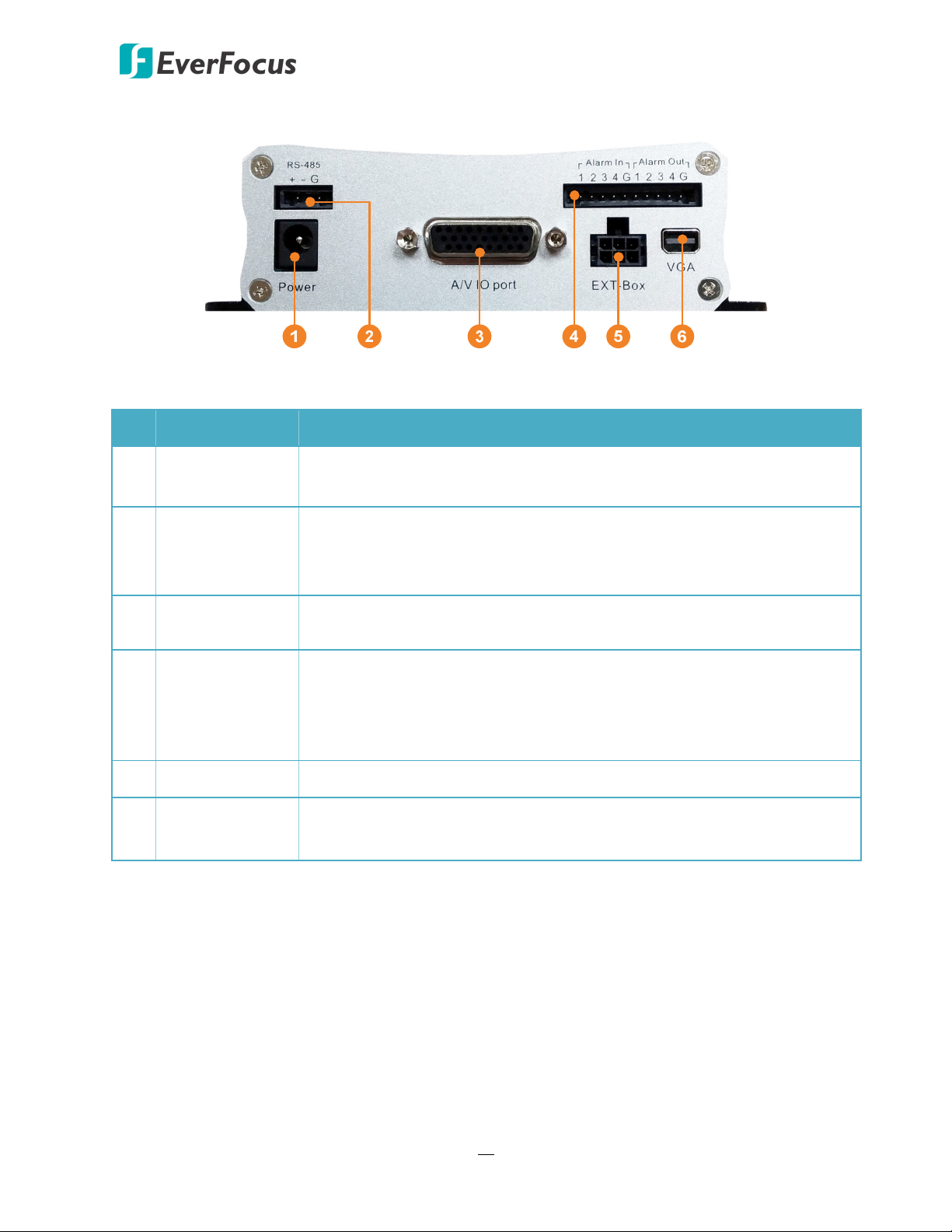
No. Name Description
Sentinel System – Video Recorder
DC Power Input
1
Connects to power source using the supplied Power Adaptor. For
details, please refer to 2.3.1 Power Input.
This function is only available for ESN41 FHD. Connects to a RS‐485
2
RS-485 Port
device such as PTZ camera. Please insert the supplied RS‐485 Terminal
Block to the RS‐485 Port in advance.
3
D-Sub Port
Connects to the video input/output and audio input/output devices
using the supplied D‐Sub Cable. Please refer to 2.3.2 D-Sub Cable.
This function is only available for ESN41 FHD. Connects up to 4 alarm
4 Alarm I/O
input and 4 alarm output devices. You can also connect to the radio‐
controlled clock for time synchronization. Please insert the supplied
Alarm I/O Terminal Block to the Alarm I/O Port in advance.
5 EXT Box This function is currently reserved. Connects to an external I/O box.
6
VGA
Connects to a monitor using the supplied VGA Cable. You can display
live view or perform the playback and OSD operations.
14
Page 25
2
Sentinel System – Video Recorder
2. Installation
2.1 Mounting
You can mount the video recorder on a Flat Surface or on a DIN Rail.
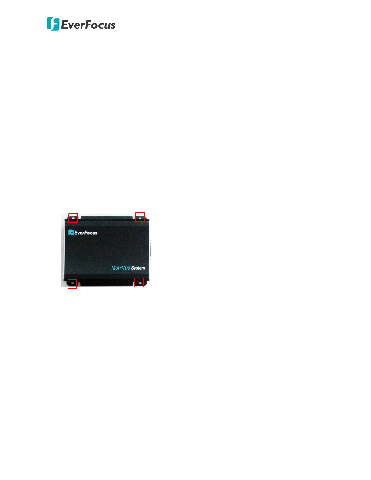
Mounting on Flat Surface
To mount the video recorder on a flat surface:
Chapter
1. Drill four holes on the mounting surface according to the hole‐position on the video recorder.
2. Insert the four supplied Mounting Screw Anchors into the holes on the mounting surface.
3. Place the video recorder on the mounting surface against the anchoring surface so that the
holes line up. Screw the video recorder to the mounting surface using the supplied four
Mounting Screws.
15
Page 26
Sentinel System – Video Recorder
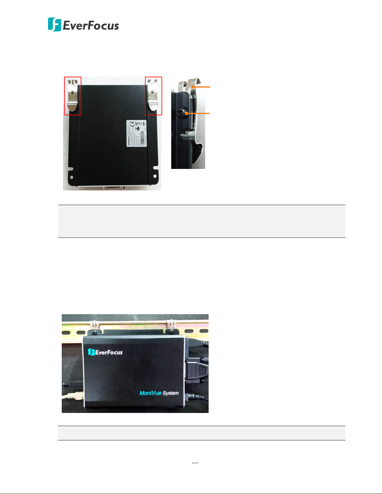
Mounting on DIN Rail
1. Screw the supplied two DIN Rail Mounting Clips to two holes on the bottom of video
recorder with the supplied two DIN Rail Mounting Screws.
DIN Rail Mounting Clip
DIN Rail Mounting Screw
Note: Depends on the way you would like to mount the video recorder on the DIN Rail
(vertically or horizontally), you can choose two holes from one of the sides (Up, Down, Left,
Right) for screwing the DIN Rail Mounting Clips.
2. Hitch the hook of the DIN Rail Mounting Clips on the upper edge of DIN rail and then push
the video recorder to the DIN rail. You will hear a clip sound, which means it has been locked
to the DIN Rail tightly.
3. A typical mounting may look like the image below. You can mount the video recorder on the
DIN rail vertically or horizontally.
Note: The supplied DIN Rail Mounting Clips are applicable to the standard 35mm DIN Rails.
16
Page 27
Sentinel System – Video Recorder
2.2 SD Card Installation
The video recorder provides SD card function for recording. Please follow the steps below to
install and activate the SD Card recording function. Up to 128GB SDHC/SDXC card capacity is
supported (see Appendix G Tested Card Brands). Note that ESN41 FHD supports 2 SDHC/SDXC
card slots and ESN41‐E FHD supports 1 SDHC/SDXC card slot.
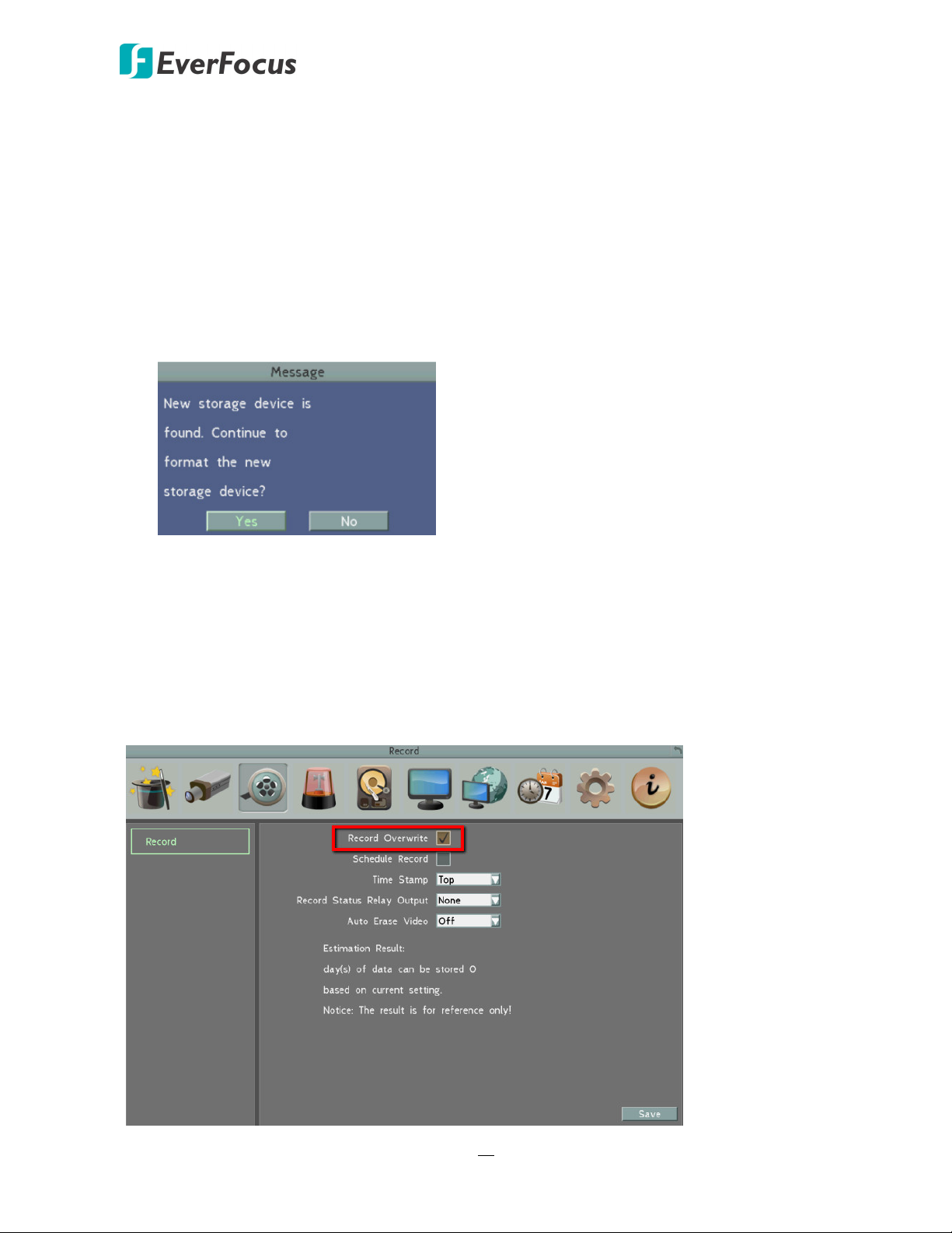
1. Insert the SD card(s) to the card slot(s) on the front panel of video recorder.
2. The video recorder will automatically detect when a new SD card has been inserted and the
below SD card format message will pop‐up. Click Yes to format the SD card. Note that only
the formatted SD card can be used for recording.
3. After formatting the SD card(s), the system will enter the Live View window. By default, the
system will automatically record all the connected channels.
After installing the SD Card, it’s recommended to enable the Record Overwrite function. The
Record Overwrite function enables the system to overwrite the recordings when the card space
is full. If Record Overwrite is not enabled, the recording function will stop when card space is full.
To enable the Record Overwrite function, please go to the OSD menu: System < Record.
17
Page 28
Sentinel System – Video Recorder
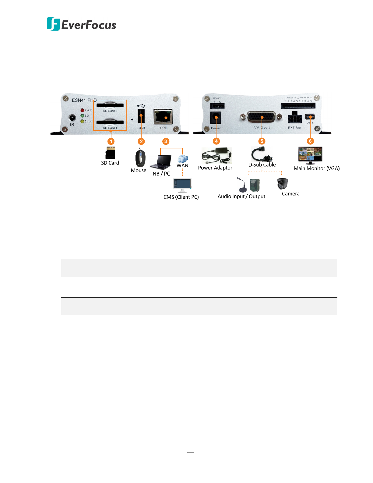
2.3 Basic Connection
After installing the video recorder, you can start connecting the external devices to the system.
The instructions below describe the basic connection to the system.
The image below uses ESN41 FHD as an example.
1. To record videos, connect a SDHC/SDXC card to the card slot (see 2.2 SD Card Installation).
2. To control the system, connect a mouse to the video recorder or use the supplied IR Remote
Control.
3. To manage the video recorder over network, use a standard RJ‐45 cable to connect the video
recorder to the network.
Note: The ESN41 FHD features PoE function, you can also power the video recorder
through the PoE port by connecting to a PoE switch.
4. To power on the video recorder, connect the video recorder to power using the supplied
Power Adaptor (see 2.3.1 Power Input).
Note: The ESN41 FHD features PoE function, you can also power the video recorder
through the PoE port by connecting to a PoE switch.
5. Connect the audio and video devices to the video recorder using the supplied D‐Sub Cable
(see 2.3.2 D-Sub Cable).
6. To view videos, connect a monitor to the VGA port using the supplied VGA Cable (see 2.3.3
Monitor Connection).
18
Page 29
Sentinel System – Video Recorder
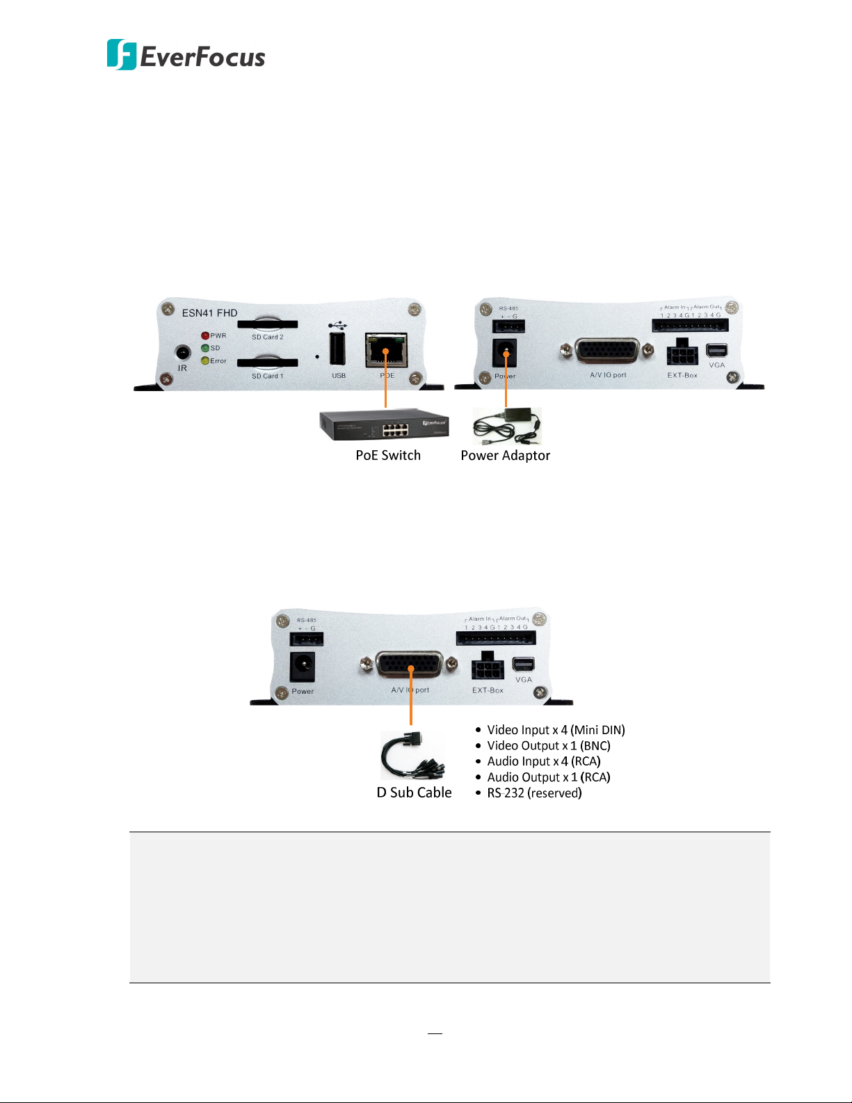
2.3.1 Power Input
You can connect the video recorder to a power source through PoE (ESN41 FHD only) or
power port.
PoE: Connect the video recorder to a PoE switch. Note that only ESN41 FHD supports PoE
function.
Power Port: Connect the video recorder to a 12VDC power source using the supplied Power
Adaptor.
2.3.2 D-Sub Cable
You can connect the video recorder to 4 cameras, 4 audio inputs, 1 audio output and 1 BNC
monitor using the supplied D‐Sub Cable. Please refer to the cable labels to identify each cable.
Note:
1. Connect the 4 cameras to the 4 video inputs (mini‐DIN cables) and the power will be
supplied to the cameras.
2. The connected speakers/microphones require a (built‐in) amplifier and external power
supply.
3. The RS‐232 function is currently reserved.
19
Page 30
Sentinel System – Video Recorder
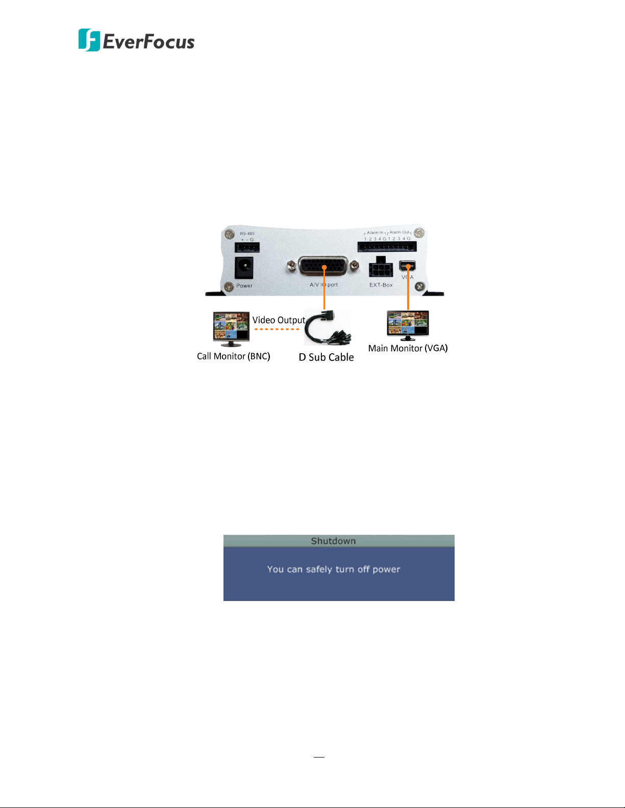
2.3.3 Monitor Connection
The video recorder has one Main Monitor port (VGA) and 1 Call Monitor port (BNC). You can
connect the monitors to the system through VGA and BNC ports. The Main and Call Monitor
ports can be used simultaneously.
with these resolution requirements.
Main Monitor: The configuration can only be operated on the Main Monitor.
Call Monitor: The call monitor can display camera streams or perform sequence mode.
Make sure that the connected monitor's specifications comply
2.4 Turning On / Off the Power
Once you have completed the basic cable connections, you are ready to turn on the system.
Simply plug in the power source. The POWER LED will light up if power is normal. Once the
system has finished loading, you can begin to set up the menu options for the system.
To turn off the power, please go to OSD Root Menu > System > System Setting > Miscellaneous
setting page, and click Shutdown (refer to 6.9.7 Miscellaneous). After the message pops up as
below, you can now turn off the power source.
20
Page 31

Sentinel System – Video Recorder
2.5 Accessing the System
You can look up the IP address and access the Web interface of the system using the IP Utility
(IPU) program, which is included in the software CD. The IP Utility can also be downloaded from
EverFocus’ Website: http://www.everfocus.com.tw Please connect the system on the same LAN
of your computer.
1. Save IP Utility Setup .exe in your computer. Double click the .exe file and follow the
on‐screen instructions to install the IP Utility.
2. Click the Finish button, the IP Utility will be automatically launched to search the IP devices
connected on the same LAN.
3. To optionally configure the Machine Name, IP Address, IP Type or Port Number using the IPU:
a. Log in the system by checking the desired model and then click the Log in icon. The
Log in dialog box appears.
21
Page 32

Sentinel System – Video Recorder
b. Type the Username and Password. Click the OK button, the status of the selected camera
will display Login.
Note:
1. The default user ID is admin and the default password is 11111111.
2. If you select more than one device that have the same user ID / password, you will
be able to log in several devices at once.
c. Right click the column to configure the setting. Click Apply Changes button to apply
and save the settings.
Note: Most networks uses DHCP to assign IP address, if you are unsure of your network
settings, please consult your network administrators for configuration details.
4. To access the Live View window, double click the IP address of the desired device, the login
window pops up. Type the user ID and password to log in. By default, the user ID is admin
and the password is 11111111.
22
Page 33

Sentinel System – Video Recorder
5. If you log in for the first time, follow the instruction steps on the interface to update the
latest Plugin version (ePlayer). After reloading the webpage, the login window pops up again.
Type the user ID and password to log in again. By default, the user ID is admin and the
password is 11111111.
Note for the first time login:
The “Download ePlayer Instruction” page will only be prompted for the first time login in order
to update the system to the latest plugin version.
When the Plug‐in blocked appears on the browser, select Always allow plug-ins on xxx, click
Done and then reload the webpage.
6. Now you will be able to see the remote live page.
23
Page 34

Sentinel System – Video Recorder
If you encounter the following problem or still can’t access the remote Web interface, please
see below:
If the Error window appears, please be sure to close ALL the Web browser windows first and
then click Retry. When the Completing the ePlayer Setup Wizard window shows up, click
Finish. Then, you can open a new browser again to access the system’s remote Web interface.
24
Page 35

Sentinel System – Video Recorder
If your PC or laptop is running with Windows, it’s required to run the browser as
administrator when first entering the remote web page of the device. Go to C:\Program Files
(x86)\Internet Explorer, right‐click the browser and then click Run as administrator.
You may need to turn off the firewall and turn User Account Control off if you still can’t see
the Remote Live View.
To turn User Account Control off, on the computer, click Start > Control Panel > System and
Security > Action Center (click Change User Account Control Settings), the User Account
Control Settings window appears. Adjust the slide bar to Never Notify and then click OK.
Restart your computer if requested.
25
Page 36

Sentinel System – Video Recorder
2.6 Connecting the System to the Network
There are three methods to connect the system to the network: Router or LAN Connection, Direct
High‐Speed Connection and One‐to‐One Connection. For more information of the network,
please refer to Appendix A. Network Overview.
2.6.1 Router or LAN Connection
This is the most common connection in which the system is connected to a router and allows
multiple users on and off site to see the system on a LAN/WAN (Internet). The camera must
be assigned an IP address that is compatible with its LAN. By setting up port forwarding on
the router, you can remotely access the cameras from outside of the LAN via the Internet. To
remotely access the Web interface, please refer to 7. Remote Access to the System. To set up
port forwarding, please consult the manual of the router or refer to Appendix B: Linksys & D-
Link Port Forwarding.
Connection Procedure:
The First step is to purchase or make a straight through cable. We recommend
purchasing one if you have never made a straight through cable. Please remember you
can not use a cross‐over network cable for this application.
Once you have a straight through cable plug one end into the LAN port on the back of
the recorder and the other into the router.
Log into the EverFocus system menu and go to the Network Setting Menu.
To let the router automatically assign an address:
Set the Network Type to DHCP. Make sure to write down the IP address and the
Gateway.
Exit from the Menu to save settings.
26
Page 37

To manually assign an address:
Go to a computer connected on the same network as the system.
Click on the Start button and choose Run.
If using Windows Vista, choose Search instead.
Type “command” and click on OK.
In Vista, you will need to double‐click on the “Command Prompt” file to open it.
In the DOS prompt, type “ipconfig” and press Enter.
The network information will be displayed on a screen similar to the one below.
In Windows Vista, look for the information that says “IP v4”.
Sentinel System – Video Recorder
Take the values for Subnet Mask and Default Gateway and input them into the
system; these values should be exactly the same in both devices. However, you
should change the last number of the IP address. For example, if the IP address of
the computer is 192.168.2.101, the system’s IP address should be 192.168.002.050.
To access the system from a computer simply open Internet Explorer and in the address
bar type:
http:// (IP address of the system)
Note: The system’s IP address will only work at the location of the system. To
connect from a different location over the Internet, see below.
27
Page 38

Sentinel System – Video Recorder
To set the system for Internet Connection through router:
The next step is to open ports within your router. Log into the router using a PC and
open the following ports.
Ports to open: 80
If your Internet service provider blocks port 80, you can change it to a different port
in the system’s Network Menu Setup; open/forward that port instead.
If you are using a Linksys or D‐Link router, see Appendix A for basic support on
setting up ports. For any other router, you will need to contact the manufacturer
for support.
To access the system from a computer simply open Internet Explorer and in the address
bar type:
http:// (the IP address given by your internet service provider)
Note: If you changed to a different port other than 80, you will need to include this
at the end of the IP address:
http:// (the IP address given by your internet service provider):portnumber
If you have a WAN Dynamic IP address and have opened the ports, go to Chapter 7 to
setup DDNS.
28
Page 39

Sentinel System – Video Recorder
2.6.2 Direct High-Speed Connection
In a Direct High‐Speed Connection, the camera connects directly to a modem without the
need for a router. You need to set the static or dynamic WAN IP address assigned by your ISP
(Internet Service Provider) in the camera’s configuration web pages. To access the camera,
just type “http://xxx.xxx.xxx.xxx”, where xxx.xxx.xxx.xxx is the IP address given by your ISP. If
you have a dynamic IP address, this connection may require that you use DDNS for a reliable
connection.
Connection Procedure:
The first step is to purchase or make a straight through cable. We recommend
purchasing one if you have never made a straight through cable. Please remember you
can not use a cross‐over network cable for this application
Once you have a straight through cable plug one end into the LAN port on the back of
the recorder and the other into the high speed modem.
Log into the EverFocus system menu and go to the Network Setting Menu.
Input the Static IP address, the Subnet Mask, and the Gateway that you obtained from
the internet service provider.
Note: If you have a dynamic IP address, you can set the system to DHCP to automatically
detect the network settings. Therefore, it can use a dynamic IP address.
Exit from the system’s Menu to save the settings.
To access the system from a computer, open Internet Explorer and in the address bar
type: http:// (IP address given by your internet service provider)
Note: When using this type of connection, only one device can be connected to the
modem at a time. You will need to use a computer at a different location to test the
connection s.
29
Page 40

Sentinel System – Video Recorder
2.6.3 One-to-One Connection
You can connect directly without using a switch, router or modem. However, only the PC
connected to the camera will be able to view the system. You will also have to manually
assign a compatible IP address to both the computer and the system. Unless the PC has
another network connection, the system will be the only network device visible to the PC. See
the diagram below:
Connection Procedure:
The First step is to purchase or make a cross‐over cable. We recommend purchasing one
if you have never made a cross‐over cable. Please remember you can not use a straight
through network cable for this application.
Once you have a cross‐over cable plug one end into the LAN port on the back of the
system and the other into the network card on the back of the computer.
Log into the EverFocus system menu and go to the Network Setting Menu.
You must use the Static IP option for this type of connection.
Assign an IP of 192.168.001.003, a Subnet Mask of 255.255.255.000, and a Gateway of
192.168.001.001. You can ignore DNS Server.
The next step is to set the computer’s network settings to match those of the system.
You will need Administrator privileges on your Windows machine to do this.
To assign a fixed IP address in Windows 2000/XP, follow the instructions below:
30
Page 41

Go to Start. Double‐click on Control Panel.
Click Network and Sharing Center.
Sentinel System – Video Recorder
Click Local Area Connection.
31
Page 42

Click Properties.
Sentinel System – Video Recorder
Click on Internet Protocol Version 4 (TCP/IPv4) and then click Properties.
32
Page 43

Select Use the following IP address. Assign an IP address of 192.168.1.2, a Subnet
Mask of 255.255.255.0, and a Default Gateway of 192.168.1.1 and then click OK.
Sentinel System – Video Recorder
Restart both of the computer and the system.
To access the system from the computer, simply open Internet Explorer and in the
address bar type: http://192.168.1.3
33
Page 44

3
Sentinel System – Video Recorder
Chapter
3. General Operation
There are two ways to control the OSD menu of the systems: with a Mouse or the supplied
handheld IR Remote Control. For details on the IR remote control, please refer to Appendix E, IR
Remote Control. This chapter will discuss the basic operations using the mouse.
3.1 USB Mouse Operation
3.1.1 How to Select a Channel / Enable Audio Out
To select a channel, on the Live View window, single‐click on the desired channel screen.
The selected screen will be highlighted by a red frame.
To toggle full screen of a channel, double‐click on a desired channel.
To switch the Audio Output channel, single‐click on the desired channel screen, the
highlighted channel will be automatically applied with the Audio Output function (an
audio icon will be displayed on the upper‐right corner of the channel). To turn on/off
the Audio Output function, click the Audio Icon at lower‐left side of the monitor.
34
Page 45

Sentinel System – Video Recorder
3.1.2 OSD Root Menu
1. Right‐click the mouse, the OSD Root Menu window appears.
2. Click on any icon to enter to the setup menus.
3. Click the button on the top‐right corner or right‐click to close the OSD Root Menu.
3.1.3 Field Input Options
You may found the following fields in the Configuration menu. Follow the instructions below
to configure the settings.
Text Box: Click on the box and an on‐screen keyboard will appear.
On-Screen Keyboard: Click on a button to input that character. The buttons on the right and
bottom have the following functions:
Caps Switch to capital letters
← Delete the letter backwards
Confirm the selection
Move to left
Move to right
Space Enter a space
35
Page 46

Sentinel System – Video Recorder
Drop-Down Box: Click on the down arrow to see all selections, then directly click on an option
to select it.
Check Box: Click on the box to enable it (checked) or disable it (unchecked).
Button: Click the button to execute the function.
Bar: Slide the bar to the left or right for adjusting the set point.
36
Page 47

Sentinel System – Video Recorder
3.2 General Operation
3.2.1 Login
In order to access systems, you may be prompted to log in for authority identification. To log in,
follow the steps below:
1. Right click on the screen to display the Root Menu. The following window appears.
2. Select the user name from the User name drop‐down list and input the password. The
default user name and password are:
User Name: admin
Password: 11111111
Note: For details on setting up multiple user accounts, please refer to 6.9.4 User
Management.
To input the password, click the Password field to bring up the on‐screen keyboard. Click on
each button to input the desired characters. When finished, click to confirm the
password.
3. Click the Login button to log in the system.
37
Page 48

Sentinel System – Video Recorder
3.2.2 Forget Your Password
1. If you forget your password, please email the Serial Number of the system to
ts@everfocus.com.tw , and then EverFocus will send you a verification code.
2. Input this verification code in the Password field of the Login window within 24 hours,
and check the Verification Mode box.
3. Click Login to log in the system.
Note: This verification code is effective within 24 hours only, so please set up a new
password in the System Setting page (refer to 6.9.4 User Management).
3.2.3 Camera Selection
You can control each camera individually by selecting that camera. To select a camera, follow
the instructions below.
Click a camera on the screen, and the selected camera will be highlighted with a red frame. All
cameras will be selected when you scrolling the mouse up / down between the first and the
last channel.
38
Page 49

Sentinel System – Video Recorder
3.2.4 Audio Selection
In order to perform the audio function, please follow the instructions below before switching
on the audio function.
Note: The Audio function is unavailable for Germany.
1. Connect the audio input/output devices to the system (see 2.3.2 D-Sub Cable). Note that
both of the audio input and output devices require a (built‐in) amplifier and external
power supply.
2. Go to Camera setting menu (OSD Root Menu > System > Camera > Camera Status).
3. Select a camera from the Camera drop‐down list.
4. Enable the Record Audio option and select an audio input device. You can select multiple
cameras to one single audio input device (there are four audio input devices).
Note that the system only provides one channel audio output. You can switch the Audio
Output function to either one from the cameras. To switch the Audio Output function to the
desired camera:
On the bottom of the live view screen, click the Audio icon to switch the Audio Output
function to the desired camera or disable the Audio Output function.
39
Page 50

4
4. OSD Root Menu
Sentinel System – Video Recorder
Chapter
No
Name Description
1 Playback Click to display the Playback Bar for viewing the recording videos. For
details, please refer to 5. Search and Playback.
2 PTZ Click to display the PTZ Control Panel for controlling the connected PTZ
cameras. For details, please refer to 4.1 PTZ.
3 Layout Click to display the Layout Switch Bar as shown below. Select a layout type
for the live view display on the Main Monitor. For details, please refer to
4.2 Layout Switching.
4 Change
Channel
Click to display the Channel Changing Bar as shown below. To switch the
selected camera to a specific channel, please refer to 4.3 Channel
Switching.
40
Page 51

Sentinel System – Video Recorder
5 Display Click to display system information icons or status icons on the live view
screen. For details, please refer to 4.4 Display.
6 Sequence Click to enter the auto sequential switching mode. Click again to disable.
For setting up the sequencing order, please refer to 6.6.2 M/T SEQ.
7 Monitor Click to switch to the call monitor settings. On the OSD Root Menu, click
the Monitor button to switch to the Call monitor. On the OSD Root
Menu, the Playback, PTZ, Zoom, Search, Copy, System and Exit icons will
gray out. You can only configure the Layout, Channel, Display and
Sequence settings for the Call Monitor. To switch to the Main Monitor,
click the button. Note that the Call Monitor can only be used to
display camera views. The functions including the layout, channel
switching, icon display, sequencing mode of the Call Monitor can only be
configured on the Main Monitor.
8 Zoom Click to enter the Zoom mode. You can zoom in the camera view up to x4
and navigate the camera view. For details, please refer to 4.6 Zoom.
9 Search Click to display the Search menu for setting up the Search mode for
playing back. For details, please refer to 5.3 Searching the Recordings for
Playback Back.
10 Copy Click to display the Copy menu for archiving the recordings or log data to
the USB storage device or FTP. For details, please refer to 4.7 Archiving
the Recordings or Log Data to the USB or FTP.
11 System Click to enter the System Setting menu. Please refer to 6. System.
12 Exit Click to bring up the Logout Confirmation window and then click Yes to
log out the system (see 4.8 Logout). To log in, please refer to 3.2.1 Login.
41
Page 52

Sentinel System – Video Recorder
4.1 PTZ
The PTZ function is currently reserved. You can use the PTZ Control Panel to control the
connected PTZ cameras. To bring up the PTZ control panel, on the OSD Root Menu, click the PTZ
button .
The following actions can be performed using the PTZ Control
Panel:
1. To bring up the PTZ OSD menu (only supported for
EverFocus eZ.HD PTZ cameras):
a. Click the Preset button.
b. Click the Preset number 95.
c. Click the Set button.
d. To close the OSD menu, click the IRIS – button.
2. To move the camera to the desired direction and angle,
click the Direction buttons.
3. To zoom in / out the camera view, click the Zoom buttons.
4. To adjust the camera focus, click the Focus buttons.
5. To adjust the Iris open to increase / decrease the amount of
light in, click the Iris buttons.
6. To program a Preset Position (if supported by the camera):
a. Move the PTZ camera to the desired position.
b. Click the Preset button.
c. Set up a preset number for the current position by
clicking the number buttons. The number will be
displayed in the number box.
d. Click the Set button to save the settings.
7. To jump to a Preset Position:
e. Click the Preset button.
f. Click the desired Preset number.
g. Click the Go button.
8. Shortcut for Preset 1 ~ 9:
a. Click digit 1 ~ 9 button without clicking any other
buttons.
b. The camera will seek that Preset Position.
42
Page 53

9. To delete a Preset Position (if supported by the camera):
a. Click the Preset button.
b. Click the desired Preset number.
c. Click the Delete button.
10. To operate the Auto Pan function, click the Auto Pan
button.
11. To operate the Pattern function, click the Pattern button.
The Pattern is the “0” Tour in Everfocus and Pelco PTZ
cameras.
12. To operate the Tour function:
a. Click the Tour button.
b. Click the desired Tour number.
c. Click the Go button.
13. To remove a pre‐configured Tour (if supported by the
camera):
Sentinel System – Video Recorder
a. Click the Tour button.
b. Click the desired Tour number.
c. Click the Delete button.
Click C to clear the entered number in the Number Box.
Click at the top‐right corner to hide the PTZ Control Panel (see 4.1.1 Express Control of PTZ).
To display the PTZ Control Panel, right‐click on the screen.
Click Exit PTZ to close the PTZ Control Panel and exit the PTZ mode.
Note: Before start using the Auto Pan, Pattern and Tour functions, you have to configure the
related settings for the connected PTZ cameras. Please refer to the User’s Manual of your PTZ
cameras.
43
Page 54

Sentinel System – Video Recorder
4.1.1 Express Control of PTZ
If the PTZ Control Panel has first been opened and then hidden, the mouse can be used to
control basic PTZ functions. Move your mouse cursor on the screen, the mouse cursor will
turn into a control icon (direction, focus or zoom) in different areas of the screen. You can
control PTZ direction, focus and zoom by clicking directly on the screen.
Direction Controls: When your mouse cursor turns into a direction icon, click on the screen
will force the camera to turn in that direction.
Focus Controls: When your mouse cursor turns into , click on the screen will focus closer
the image. When your mouse cursor turns into , click on the screen will focus farther the
image.
Zoom Controls: When your mouse cursor turns into , click on the screen will zoom in the
image. When your mouse cursor turns into , click on the screen will zoom out the image.
44
Page 55

4.2 Layout Switching
The system provides the following layout options.
To change layout, follow the steps below:
1. Right‐click to bring up the OSD Root Menu.
2. Click the Layout icon .
3. Click on the desired layout.
4.3 Channel Switching
Sentinel System – Video Recorder
You can switch the selected camera to a specific channel. Follow the steps below:
1. On the live view screen, select a camera, the selected camera will be highlighted with a red
frame.
2. Right‐click to display the OSD Root Menu.
3. Click the Change Channel icon , the Change Channel bar appears.
4. Select a channel by clicking on it, the selected camera will be switched to that channel.
45
Page 56

Sentinel System – Video Recorder
4.4 Display
You can display system and camera status on the live view screen. Follow the steps below:
1. Click the Display icon on the OSD Root Menu to display the system and camera status.
You can continue click on the icon to switch among the display modes. There are four modes
provided: (1) Display both the camera and system status icons. (2) Display only the camera
status icons. (3) Display only the system status icons. (4) Hide both the camera and system
status icons.
2. The following icons will be displayed at the top side of each camera stream to show each
camera’s status.
Recording Playback Fast forward Fast backward Back pause
Alarm Motion Video loss Uninstall Audio On Audio In
3. The following icons will be displayed at the bottom of the monitor to show the system status.
Audio On Audio Off Alarm Motion Video loss
No network Main Call Sequence Event
46
Page 57

Sentinel System – Video Recorder
4.5 Sequence
The sequence function is used to display each channel in sequence mode. To enable this
function:
Click the Sequence icon to enter the sequential switching mode. The system will display
one channel at a time in full screen. The channels will be displayed in the sequence and for the
amount of time as configured in the System > Display Setting > M/T SEQ submenu. The default
setting is channels 1~4 with a dwell time of 3 seconds each – repeated. Please refer to 6.6.2 M/T
SEQ for detailed information.
4.6 Zoom
You can zoom in the camera view up to 4X and navigate the camera view using the mouse.
To enter the Zoom mode:
1. Select a camera and then click the Zoom button on the OSD Root Menu to zoom in
the camera view to 2X. The ZOOM 2X stamp will be displayed on the top screen.
2. Navigate the camera view to the desired position by moving your mouse cursor over the
camera view. The mouse cursor will turn into a direction icon when you move your mouse
cursor to different portion on the camera view. Click directly on the screen can move to that
direction.
47
Page 58

Sentinel System – Video Recorder
3. Right‐click the screen, the Zoom Bar appears in the middle of the screen.
4. Click to zoom in the camera view up to 4X.
5. Click the Logout button to log out the Zoom mode.
48
Page 59

Sentinel System – Video Recorder
4.7 Archiving the Recordings or Log Data to the USB or FTP
You can archive the recordings or log data (event and motion) to the USB storage device or FTP
server. On the OSD Root Menu, click the Copy icon , the following menu appears. Please
insert a USB storage device to the system or set up the FTP configurations in advance (see 6.7.4
FTP).
Camera: Select the desired cameras.
Data Type: You can copy the recordings of selected cameras from main stream, or sub stream.
Player: Check the box to include the EFPlayer program in the copy. You can use the
EFPlayer on a computer to play back the recordings. Please see the instructions on the next page.
Start Date / Time: Click to bring up the on‐screen keyboard / clock to select the start date / time.
End Date / Time: Click to bring up the on‐screen keyboard / clock to select the end date / time.
Copy To: Select a destination (USB or FTP) for the recordings or log data to be archived to.
Copy: Click to start archiving.
49
Page 60

Sentinel System – Video Recorder
EFPlayer:
You can use the EFPlayer to play back the archived recordings from EverFocus’ DVR/NVR.
Unzip the EFPlayer file and double‐click to open it as below. The EFPlayer can only display up to 16
channels at a time.
No. Name Function Description
1 Information Shows the recording information of the device, including model
of the recorder, recording start time / date, current playback
time, recording end time / date.
2 Load Click to select a recording file and open it.
3 Save as AVI Click to archive the recording file of 1 channel and save as AVI
format.
4 Time Search Click to search a recording from a selected time.
5 Channel Switch Click to switch channel bar between CH1~16 and CH17~32.
6 Time Bar Move the time bar to a desired time to play back the recording
from that time.
7 Playback Controls
: Click to fast reverse / fast forward.
50
Page 61

Sentinel System – Video Recorder
: Click to reverse play /play.
: Click to pause playing back.
8 Snapshot Click to take a snapshot of the channels displayed on the UI. You
can save the snapshot file to a desired location.
9 Mute Click to mute; click again to turn off the mute function.
10 Volume Drag to increase or lower the volume.
11 Scale Out / In Click to adjust time scale.
12 Screen Division
: Click to display the channels to fit the screen. :
Click to select a desired screen division display mode (1, 4, 9, 16
screen division display modes). If the channels are more than the
screen divisions, you can select the same screen division display
mode to change the channels on the screen.
13 Speed Shows the fast reverse / forward speed (up to 64X).
51
Page 62

Sentinel System – Video Recorder
4.8 Logout
You can log out the system by clicking the Exit icon on the OSD Root Menu to bring up the
Logout Confirmation window. Click “Yes” when you are ready to logout of the system. You will
need to login again before accessing the OSD Root Menu.
If you do not need the Login / Logout step before entering the Root Menu, please uncheck the
Login box in the User Management setting page. For more details, please refer to 6.9.4 User
Management.
52
Page 63

Sentinel System – Video Recorder
4.8.1 Temporarily Logout
You can temporarily log out the system by clicking the Exit icon on the OSD Root Menu.
This function is designed for use in conjunction with the Covert Camera function. Once you
click the Exit icon, the camera streams will be hidden on the Live View / Sequence Mode.
However, the system will still record the videos and the recordings can be played back.
To enable the Temporarily Logout function, follow the steps below:
1. Ensure the Login box is Unchecked (OSD Root Menu > System > System Setting >
User Management).
53
Page 64

Sentinel System – Video Recorder
2. Select the cameras to be hidden once enabling the Temporarily Logout function and then
check the Covert box (OSD Root Menu > System > Camera > Basic).
3. Click the Exit icon on the OSD Root Menu, the Logout menu appears.
4. Click the Yes button and the selected camera streams will be hidden on the Live View /
Sequence Mode.
5. To disable the Temporarily Logout function, simply right‐click the screen to bring up the
OSD Root Menu, and then you can start controlling the system.
54
Page 65

5
Sentinel System – Video Recorder
Chapter
5. Search and Playback
You can use the Quick Playback function to play back the recordings start from the pre‐configured
time or use the Search functions to search for the desired recordings for playing back.
5.1 Quick Playback
To start using the Quick Playback function, follow the steps below:
1. To set up the start time of the playback recording, check the Quick Playback box in the
Express setting page (OSD Root Menu > System > Express) to enable the configured time in
the field below.
2. Enter the desired time for playing back the recording. Take 60 seconds for example, if the
current system clock time is 17:35:00, the start time for the playback recording will start
from 17:34:00 (60 seconds ago from 17:35:00).
3. On the Live View Window, select a desired camera, right‐click to bring up the OSD Root
Menu and then click the Playback button .
4. The recording will be played back and the Playback Bar appears on the bottom of the screen.
55
Page 66

Sentinel System – Video Recorder
5.2 Playback Bar
The playback bar is the fastest way to show video from the exact time which users want to see.
The playback bar allows users to see both a timeline and the current playback indicator. Users can
then click the timeline to move the indicator to the desired position.
No. Name Description
1 Date/Time Click to set up the start time of playback recording.
2 Time Bar Move the slider to the left / right on the Time Bar to select the time
for playing back. The status of each camera is presented by
different colors on the Time Bar. GreenNormal,
OrangeMotion, BlueVideo Loss, RedAlarm Event.
3 Playback Speed Indicates the current Playback Speed.
4 Express Copy Click to bring up the Copy menu for archiving the recordings / log
data to the USB storage device or DVD burner. For details, please
refer to 4.7 Archiving the Recordings or Log Data to the USB or FTP.
5 Close Click to hide the Playback Bar. To bring up the Playback Bar again,
move your cursor to the lower side of the screen.
6 Main /Sub Stream Click to select the recorded data from main or sub stream. This
function is only functional for single view in the Quick Playback
mode. To operate this function, on the Live View Window, double‐
click a channel to display its single view, right‐click to bring up the
OSD Root Menu and then click the Playback button .
7 Fast Reverse Click to play the recorded data in fast reverse.
8 Reverse Play/Pause Click to play the recorded data in reverse at normal speed. Click
this button again to Pause the reverse playback. Click the Stop
button to stop all playback actions and exit the playback area.
9 Stop Click to stop all playback actions and exit the playback mode.
56
Page 67

Sentinel System – Video Recorder
No. Name Description
10 Play/Pause Click to play the recorded data forward. Click this button again to
Pause the playback.
11 Fast Forward Click to play the recorded data in fast forward.
12 Time Scale L1: Entire Time Bar scale is 30 days.
L2: Entire Time Bar scale is 2 weeks.
L3: Entire Time Bar scale is 1 week.
L4: Entire Time Bar scale is 1 day.
L5: Entire Time Bar scale is 1 hour.
L6: entire Time Bar scale is 30 minutes.
13 Time Bar Scale Use the + and - buttons to adjust the time scale range for the bar.
The scale range includes 6 options (levels). When changing the
14
level, the Start Time and End Time will change.
15 Start Time Indicates the playback start time.
16 Current Playback
Indicates the current playback time.
17 End time Indicates the playback end time.
57
Page 68

Sentinel System – Video Recorder
5.3 Searching the Recordings for Playing Back
You can search the recordings for playing back by using the Search menu. On the left side of the
Search menu, select Time Search, Event Search, Smart Search, Snapshot Search or POS Search
to enter to the setup menu.
To bring up the Search menu:
Right‐click to bring up the OSD Root Menu, and then click the Search icon .
5.3.1 Time Search
Start Date: Click to bring up the on‐screen keyboard to select the date.
Start Time: Click to bring up the on‐screen clock to select the time.
Play: Click to start playing back.
58
Page 69

Sentinel System – Video Recorder
5.3.2 Event Search
Start Date / End Date: Click to bring up the on‐screen keyboard to select the start / end date.
Start Time / End Time: Click to bring up the on‐screen clock to select the start / end time.
Camera: Select the desired cameras to be searched.
Event: Select an event type to be searched.
Search: Click to start searching. The search results will be listed in the Event List menu as
shown below.
Copy to: Select a copy destination (USB or FTP) to copy the selected recordings to.
Player: Check the box to include the EFPlayer program in the copy. You can use the
EFPlayer on a computer to play back the recordings. To use the program, please refer to 4.7
Archiving the Recordings or Log Data to the USB or FTP.
Copy: Click to start copying the event recording files.
Previous / Next: Click to go to the previous / next page.
Play: Click to playback the selected items.
59
Page 70

Sentinel System – Video Recorder
5.3.3 Smart Search
The Smart Search function allows users to search for the motion event recordings. You can
set up the motion areas in this setup menu and then search for the motion events within the
specified time.
Start Date / End Date: Click to bring up the on‐screen keyboard to select the start / end date.
Start Time / End Time: Click to bring up the on‐screen clock to select the start / end time.
Camera: Select a desired camera to be searched.
Grid Setting: Click to set up the motion areas. The Motion Grid Setup menu appears.
Search: Click to start searching. The search results will be listed in the Event List menu.
To set up the Motion Grid:
1. Click the Grid Setting button.
2. To set up a motion area, drag a rectangle with your mouse (from top to bottom / upper‐
left to lower‐right). The selected areas will be highlighted in green (see image below).
3. To delete a motion area, drag a rectangle with your mouse (from bottom to top / lower‐
right to upper‐left).
4. Follow Step 2 to set up multiple motion areas if necessary.
5. Click the Save and Back button to save the settings and then return to the Smart Search
menu.
60
Page 71

Sentinel System – Video Recorder
Set All: Click to select the entire area.
Clear All: Click to clear all the selected areas.
Save and Back: Click to save the configured motion areas and return to the Smart
Search menu.
Cancel: Click to cancel all changes and return to the Smart Search menu.
5.3.4 Snapshot Search
You can display video frames in snapshot and resume a video from where the snapshot has
been set up.
Search Date: Click to bring up the on‐screen keyboard to select the date.
Search Time: Click to bring up the on‐screen clock to select time.
Search Direction: Click to search forward / backward based on the setup time above.
Search Camera: Select a desired camera to be searched.
Result Interval: Click to set up the interval for the snapshots. For example, if you select 5
minutes, the video frame will be snapshotted with 5‐minute interval (see image below).
Search: Click to start searching. The search results will be displayed (see image below).
61
Page 72

Sentinel System – Video Recorder
To resume the video:
1. Click the Search button, the search results will be displayed. In this picture, you can see
the time layouts on the upper‐left corner of each snapshot, which are set up with 5‐
minute interval. To change the interval, configure Result Interval on the Snapshot Search
page.
2. Right‐click on the screen, the Resume Playback Bar appears in the middle of the screen.
3. Click the Previous or Next buttons to display the previous / next snapshots.
4. Select a snapshot by clicking on the snapshot, the selected snapshot will be highlighted
with a white frame.
5. Click the Play button to resume the video.
6. Click the Close button to close the Resume Playback Bar and then return to the Snapshot
Search menu.
62
Page 73

Sentinel System – Video Recorder
5.3.5 POS Search
The POS Search function allows users to search and play back the recordings with the POS
transaction data within a specific time.
Start Date / End Date: Click to bring up the on‐screen keyboard to select the start / end date.
Start Time / End Time: Click to bring up the on‐screen clock to select the start / end time.
POS String: Click to bring up the on‐screen keyboard. Type any desired keyword to search the
specific transaction data.
Search: Click to start searching. The search results will be listed in the Event List menu as
shown below.
Previous / Next: Click to go to the previous / next page.
Play: Click to playback the selected items.
You need to set up the POS settings before searching the video with POS transaction data.
Please follow the steps below:
1. Connect the POS system to the RS‐485 port at the rear panel of the system.
2. Make sure the RS‐485 settings of the system are the same as those of the POS system.
Select the Text Insert in the Type drop‐down list. (OSD Root Menu > System > System
Setting > I/O control).
63
Page 74

Sentinel System – Video Recorder
3. Check the Text Insert box in the Monitor OSD setting page to display the transaction data
on the screen (OSD Root Menu > System > Display > Monitor OSD).
4. The transaction data, such as date, time, item, price and any customized information,
synchronized with the surveillance video will be displayed on the screen, shown as the
image below.
64
Page 75

6
Sentinel System – Video Recorder
Chapter
6. System
The systems can be configured through a series of menus on screen by using a Mouse or the
supplied IR Remote Control. The following operations are examples of using a Mouse. This
chapter describes the functions and options of the System Setting in the on‐screen display (OSD)
menus. Right‐click the mouse, the OSD Root Menu appears. Click the System icon , the
following Configuration Menu appears.
65
Page 76

Sentinel System – Video Recorder
List of Configuration Options:
Please find the topic of interest by referring to the section prefixed to each option.
6.1 Express
6.2.1 Basic Setting
6.2 Camera
6.2.2 Adjust Setting
6.2.3 eZ Hopper
6.3 Record
6.4.1 Alarm
6.4 Event
6.4.2 Video Loss
6.4.3 Motion
6.4.4 Other
6.5 Storage
6.6 Display Setting
6.7 Network
6.8 Schedule
6.9 System Setting
6.10 System Information
6.5.1 Storage
6.5.2 Lock/Format
6.6.1 Monitor OSD
6.6.2 M/T SEQ
6.7.1 LAN
6.7.2 Email
6.7.3 DDNS
6.7.4 FTP
6.7.5 Alarm Server
6.7.6 Remote/Mobile
6.7.7 Network Test
6.8.1 Express Setup
6.8.2 Holidays
6.8.3 Schedule
6.9.1 Date / Time
6.9.2 Daylight Saving Time
6.9.3 User Group
6.9.4 User Management
6.9.5 I/O Control
6.9.6 EKB200 Setting
6.9.7 Miscellaneous
6.10.1 System
6.10.2 Log
66
Page 77

Sentinel System – Video Recorder
6.1 Express
This menu is used to configure global express settings for all cameras.
Date: Click to bring up the on‐screen keyboard to set up the system date.
Time: Click to bring up the on‐screen clock to set up the system clock.
Record Mode: Select a recording mode from the drop‐down list.
Blank: Select this option for all cameras to keep the current individual record settings without
any changes. Please refer to 6.8.1 Express Setup for more details.
Normal+Event: Set all cameras to the Continuous and Event recording mode. Set up the
estimated number of hours per day for event recording. For details, please refer to Appendix
D. Express Setup Recording Value Selection Rules.
Event Only: Set all cameras to the Event only recording mode. Set up the estimated number
of hours per day for event recording. For details, please refer to Appendix D. Express Setup
Recording Value Selection Rules.
Schedule Record: Set all cameras to the Schedule recording mode.
Record With: Select a record method.
Blank: Select this option for all cameras to keep the current individual record method without
any changes.
Preset Settings: Select this option and further set up the recording quality. For details, please
refer to Appendix D. Express Setup Recording Value Selection Rules.
Recording Days: This option is not available for Schedule Record. Set up the maximum
recording days. For details, please refer to Appendix D. Express Setup Recording Value
Selection Rules.
67
Page 78

Sentinel System – Video Recorder
Miscellaneous:
Quick Playback: Check the box to enable the Quick Playback function as described below.
Playback From X Seconds ago: When the system is put into playback mode, it will begin playing
from the selected time. Choose from 60 to 3600 seconds prior to the present time.
Save: Click to save and apply the settings to the system. The system will automatically adjust the
recording frame rate according to your settings.
68
Page 79

6.2 Camera
You can configure the settings for individual cameras.
6.2.1 Basic Setting
Sentinel System – Video Recorder
Camera: Select a camera to be configured.
Title: Click to bring up the on‐screen keyboard for assigning a title for the selected camera.
Each title supports up to 16 characters.
Install: Check the box to enable the selected camera. If this box is unchecked, the system will
not get the camera streaming.
Covert: Check the box to hide the camera stream in Live View and Sequence modes.
However, the system will still record the videos and the recordings can be played back by
users who have the privilege to playback. For details on enabling the Covert function, please
refer to 4.8.1 Temporarily Logout.
Record Mode: Select a record mode from the drop‐down list.
Normal+Event: Continuous and Event recordings.
Event Only: Event recordings only.
69
Page 80

Sentinel System – Video Recorder
Main / Sub Resolution: Select the most suitable resolution for the Main Stream and Sub
Stream.
Record Quality: Select a recording quality for the Main Stream and Sub Stream. The options
include Low, Basic, Standard, High and Superior. The higher the quality, the more the storage
space is used.
Normal Speed: Select a frame rate per second (FPS) for continuous recording. The speed is
limited by the maximum total recording capacity of the system as allocated across all the
installed cameras, with upper limit of 30 FPS (NTSC) / 25 FPS (PAL) per individual camera
respectively (real time recording).
Event Speed: Select a frame rate per second (FPS) for event recording.
Ratio: Select 4:3, 16:9 or Stretch for camera display on the layout screen. For more
information about 4:3 and 16:9 aspect ratio, please refer to 6.2.1.1 Display Aspect Ratio.
Record Audio: Check the box to enable audio recording on the system, and then select an
audio input device.
PTZ ID: This function is currently reserved. Select ON or OFF.
Select ON if the PTZ camera is connected to the system through RS‐485. To allow the system
to recognize and then control the connected PTZ camera, you have to set up an ID for the PTZ
camera. Select On and then enter an ID for the camera. This ID must match the ID address set
up on the PTZ camera. For setting up the ID address on the PTZ camera, please refer to the
User’s Manual of your PTZ camera.
Select OFF if the PTZ camera is connected to the system through coaxial cable (BNC Video
Input), so users can then operate Zoom, Focus, Iris, Direction, Auto Pan, Preset, Tour and
Pattern functions to the PTZ camera through the system directly.
PTZ Speed: This function is currently reserved. Select a PTZ speed from the PTZ Speed drop‐
down list for the camera to move to the directions when you use the direction buttons during
the configuration period.
Apply To: Click the button to apply the same settings to the desired cameras. Note that only
the cameras support the same resolution can be applied with the same settings.
Save: Click to save the settings.
70
Page 81

Sentinel System – Video Recorder
6.2.1.1 Display Aspect Ratio
It is recommended to select the same ratio of the screen resolution and the camera live view
display to avoid black bars showing on the live view screen as the images below.
If you select 1920x1080 (16:9) screen resolution in the Screen Mode drop‐down list (see 6.6.1
Monitor OSD), it is recommended to also change the camera live view display to 16:9 aspect
ratio in the Ratio drop‐down list (see 6.2.1 Basic Setting).
If you select 800x600, 1024x768 or 1280x1024 (4:3) screen resolution in the Screen Mode
drop‐down list (see 6.6.1 Monitor OSD), it is recommended to also change the camera live
view display to 4:3 aspect ratio in the Ratio drop‐down list (see 6.2.1 Basic Setting).
Screen Mode: 800x600 / 1024x768 /1280x1024 (4:3)
Camera Ratio: 16:9 Camera Ratio: 4:3
71
Page 82

Sentinel System – Video Recorder
6.2.2 Adjust Setting
You can adjust the Brightness, Contrast and Color of the selected camera.
Camera: Select a camera to adjust the following settings.
Brightness: Move the bar to adjust the brightness.
Contrast: Move the bar to adjust the contrast.
Color: Move the bar to adjust the color.
Advanced: Click to bring up the UTC Panel and then click the Enter button to enter the
camera’s OSD menu for controlling and adjusting the camera setting. All EverFocus’ eZ.HD
cameras and other brands’ AHD cameras enabled with UTC function are supported. For more
details about eZ.Controller function, please refer to 1.2 eZ.Controller Function Description.
1. Use the direction buttons on the UTC
Panel to control the camera’s OSD
setting menu.
2. To exit the camera OSD setting, click
the Exit button to return to the Adjust
setting page.
Apply To: Click the button to apply the same settings to the desired cameras.
Save: Click to save the settings.
72
Page 83

Sentinel System – Video Recorder
6.2.3 eZ Hopper
You can just use one mouse to control up to 16 DVRs/NVRs in the same LAN network by
enabling the eZ Hopper function.
Note: Before using this function, you need to set up all the monitors to be the same
resolution, please refer to 6.6.1 Monitor OSD.
Set up one DVR or NVR to be the Main Server, and the rest to be the Sub Servers. Then, you
just need to connect a mouse to the Main Server, and you will be able to move its cursor
across all the connected monitors of the Main and Sub Servers and to control their OSD
menus respectively.
Follow the steps below to set up the eZ Hopper function:
For the Main Server:
1. Select Main Server in the Mode drop‐down list, and check the Enable box.
73
Page 84

Sentinel System – Video Recorder
2. The position of each device on the OSD layout represents the physical positions of your
monitors which you should arrange and place in the setup environment.
3. Click an IP address field to enter the IP address of a Sub Server and the first Sub Server
must be adjacent to Main Server on the OSD layout (DVR 2 or DVR 5), or it won’t work.
4. Set up the rest of the Sub Servers by entering their IP addresses, and please note that the
Sub Servers must be adjacent to one another on the layout, or it won’t work.
5. Click Save to save the setting.
74
Page 85

Sentinel System – Video Recorder
For the Sub Server:
1. Select Sub Server in the Mode drop‐down list, and check the Enable box.
2. Enter the IP address of the Main Server, and click Save.
3. When the message pops up as below, the eZ Hopper function is enabled. So, you can now
use the mouse connected to the Main Server to control this Sub Server’s OSD.
4. Follow the above 3 steps to set up the rest Sub Servers.
75
Page 86

6.3 Record
You can configure the basic recording settings on the storage.
Sentinel System – Video Recorder
Record Overwrite: Check the box to overwrite the storage when it is full. Note that unless this
box is checked, or the system will stop recording when the Storage is full. The use of record
overwrite is strongly recommended. If you do not use this feature, please be sure to enable the
Event setting for Storage Full for notification (see 6.4.4 Other).
Schedule Record: Check the box to record by the schedule. Please see 6.8 Schedule Setting for
more details.
Time Stamp: Select Bottom or Top to record the system date and time on the bottom / top of the
image. Select off will not record the system date and time in the recordings.
Record Status Relay Output: Select a number to monitor the recording status of the selected
alarm relay. The recording status (Recording On / Recording Off) of the selected alarm relay will
be transmitted to the alarm output device.
Auto Erase Video: The system will automatically erase video after it has been on the Storage for
the selected number of days. To use the maximum Storage space, choose “OFF”. (See Record
Overwrite and notes above.) This feature is useful if local rules and regulations require recorded
video to be discarded after a specific number of days, or to limit the retention of older recorded
video to clear space in anticipation of event recording.
Estimation Result: Shows the remaining storage space.
Save: Click to save the settings.
76
Page 87

Sentinel System – Video Recorder
6.4 Event
You can configure the Alarm, Video Loss, Motion and Other settings in this menu.
6.4.1 Alarm
Alarm: Select an Alarm input number.
Enable: Check the box to enable the Alarm trigger function for the selected alarm input.
Log: Check the box to record alarm events to log data.
Pre-alarm Record: Check the box to start copying the recordings to the Storage from 5
seconds before the alarm event occurs. The pre‐alarm recording rate will follow the Normal
Speed configured in the earlier section (see 6.2.1 Basic Setting). Note that the Pre‐Alarm
recording time may be reduced from 5 seconds when the system loading is too heavy, e.g.,
when all channels are triggered for pre‐alarm recording simultaneously.
Buzzer: Check the box to enable the buzzer when an alarm event is triggered.
Email Notify: Check the box to send email notification with a snapshot file when an alarm
event is detected. Email operation requires valid email entered in the Email setup menu (see
6.7.2 Email).
77
Page 88

Sentinel System – Video Recorder
Network Alarm: Check the box to send out a network alarm to a client PC when an alarm
event occurs. This feature works with EverFocus’ CMS software. You will need to configure
the Alarm Server for the system to send network alarms to the client PC (see 6.7.5 Alarm
Server).
Auto Lock: Check the box and the events will be recorded in a write protected segment of the
Storage (will not be overwritten). The system will lock a period of time when the alarm occurs.
The length of the time depends on system setting (see 6.5.2 Lock / Format).
FTP Upload: Check the box to enable uploading recordings to the FTP server function. To
setup the FTP server, please refer to 6.7.4 FTP.
FTP Upload File Type: Select MP4 file type to upload videos to FTP server; select JPEG file
type to upload snapshots to the FTP server.
Alarm Output: Select an alarm output number. When an alarm is triggered, the signal will be
transmitted through the selected alarm output relay.
Output Type: Select an output type when an alarm is triggered.
Timeout: Select this option and then set up the Timeout Duration in the field below, the
alarm output will last for the setup duration time (0 ~ 150 seconds).
Permanent: Alarm will remain active until the user presses the “Enter” key on the IR
Remote Control or resets the alarm remotely.
Transparent: Alarm output remains as long as the alarm input is active.
Trans + Timeout: Alarm output continues until event ends, then continues for the setup
duration time (0 ~ 150 seconds).
Timeout Duration: This function only appears when you select Timeout or Trans + Timeout
options in the Output Type drop‐down list. Select a duration time for the motion event. The
alarm output will last for the setup duration time between 1 and 150 seconds.
Main Monitor/Call Monitor: Select Full Screen to force the camera associated with the
selected alarm number to display full screen on the monitor. The full screen camera view will
last according to the Output Type selected in the field above.
Record: Select a camera to start recording when the associated alarm number is triggered.
Input Type: Select an input type when the selected alarm number is triggered. The options
include N.O. and N.C.
Active Camera: This function is for associating an alarm trigger with a specific camera. For
example, if you set up an external motion detector near Camera 2, you can select Camera 2 in
this field. The alarm will be associated with this camera for full screen display, event logging
and PTZ actions.
PTZ: This function is currently reserved. If the Active Camera selected above is a PTZ camera,
you can further set up the PTZ actions in this field.
The following time synchronization function must work with the radio-controller clock.
Time Sync Enable: Check to enable the time synchronization with the connected radio‐
controlled clock.
78
Page 89

Sentinel System – Video Recorder
Time Sync Interval: Select a time sync interval time (by hour) for the system to synchronize
the time with the radio‐controlled clock.
Time Sync Range: The time sync range means the allowed time difference between the
system and the radio clock. If the time difference exceeds the entered time sync range (by
second), the system cannot be synchronized unless you manually set up the exact same time
as the clock or within the time sync range.
For example, if the radio‐controlled clock time is 12:00:00 and you enter 30 seconds for the
time sync range, the allowed time difference between the system and the clock should be
within 30 seconds which means the system time can be 11:59:30 ~ 12:00:30.
Time Sync Range 30 Seconds 60 Seconds
Radio‐controlled Clock time 12:00:00 12:00:00
System time 11:59:30~12:00:30 11:59:00~12:01:00
First Sync of: Enter a first sync start time.
Apply To: Click the button to apply the same settings to the desired cameras.
Save: Click to save the settings.
6.4.1.1 Connect a Radio Clock to the System
To use a Radio Clock, you need to connect it to the alarm inputs of the system. Note that only
ESN41 FHD features alarm I/O function.
Connection Diagram:
Connect the positive (+) wire to either one from the alarm input (1~4) and negative (‐) wire
to the Ground pin on the Alarm I/O of the system.
79
Page 90

Sentinel System – Video Recorder
6.4.2 Video Loss
You can enable the Video Loss Event function and configured the video loss event
notifications in this menu.
Camera: Select a camera to be configured.
Enable: Check the box to enable the Video Loss event settings for the selected camera.
Log: Check the box to record video loss events to log data.
Pre-alarm Record: Check the box to start copying the recordings to the Storage from 5
seconds before the alarm event occurs. The pre‐alarm recording rate will follow the Normal
Speed configured in the earlier section (see 6.2.1 Basic Setting). Note that the Pre‐Alarm
recording time may be reduced from 5 seconds when the system loading is too heavy, e.g.,
when all channels are triggered for pre‐alarm recording simultaneously.
Buzzer: Check the box to enable the buzzer when a video loss event is triggered.
Email Notify: Check the box to send email notification when a video loss event is detected.
Email operation requires valid email entered in the Email setup menu (see 6.7.2 Email).
Network Alarm: Check the box to send out a network alarm to a client PC when video loss
event occurs. This feature works with EverFocus’ CMS software. You will need to configure
the Alarm Server for the system to send network alarms to the client PC (see 6.7.5 Alarm
Server).
Alarm Output: Select an alarm output number. When an alarm is triggered, the signal will be
transmitted through the alarm output relay.
80
Page 91

Sentinel System – Video Recorder
Output Type: Select an output type when an alarm is triggered.
Timeout: Select this option and then set up the Timeout Duration in the field below, the
alarm output will last for the setup duration time (10 ~ 150 seconds).
Permanent: Alarm will remain active until the user presses the “Enter” key on the IR
Remote Control or resets the alarm remotely.
Transparent: Alarm output remains as long as the alarm input is active.
Trans + Timeout: Alarm output continues until event ends, then continues for the setup
duration time (10 ~ 150 seconds).
Timeout Duration: This function only appears when you select Timeout or Trans + Timeout
options in the Output Type drop‐down list. Select a duration time for the motion event. The
alarm output will last for the setup duration time between 10 and 150 seconds.
Apply To: Click the button to apply the same settings to the desired cameras.
Save: Click to save the settings.
81
Page 92

Sentinel System – Video Recorder
6.4.3 Motion
You can enable the Motion Event function and configured the related settings including
motion event notifications and motion areas in this menu.
Camera: Select a camera to be configured.
Enable: Check the box to enable the Motion Event settings for the selected camera.
Log: Check the box to record motion events to log data.
Pre-alarm Record: Check the box to start copying the recordings to the Storage from 5
seconds before the alarm event occurs. The pre‐alarm recording rate will follow the Normal
Speed configured in the earlier section (see 6.2.1 Basic Setting). Note that the Pre‐Alarm
recording time may be reduced from 5 seconds when the system loading is too heavy, e.g.,
when all channels are triggered for pre‐alarm recording simultaneously.
Buzzer: Check the box to enable the buzzer when a motion event is triggered.
Email Notify: Check the box to send email notification when a motion event is detected. Email
operation requires valid email entered in the Email setup menu (see 6.7.2 Email).
Network Alarm: Check the box to send out a network alarm to a client PC when motion
occurs. This feature works with EverFocus’ CMS software. You will need to configure the
Alarm Server for the system to send network alarms to the client PC (see 6.7.5 Alarm Server).
Auto Lock: Check the box and the events will be recorded in a write protected segment of the
Storage (will not be overwritten). The DVR will lock a period of time when the alarm occurs.
The length of the time depends on system setting (see 6.5.2 Lock / Format).
82
Page 93

Sentinel System – Video Recorder
FTP Upload: Check the box to enable uploading recordings to the FTP server function. To
setup the FTP server, please refer to 6.7.4 FTP.
FTP Upload File Type: Select MP4 file type to upload videos to FTP server; select JPEG file
type to upload snapshots to the FTP server.
Alarm Output: Select an alarm output relay. When an alarm is triggered, the signal will be
transmitted through the selected alarm output relay.
Output Type: Select an output type when an alarm is triggered.
Timeout: Select this option and then set up the Timeout Duration in the field below, the
alarm output will last for the setup duration time (10 ~ 150 seconds).
Permanent: Alarm will remain active until the user presses the “Enter” key on the IR
Remote Control or resets the alarm remotely.
Transparent: Alarm output remains as long as the alarm input is active.
Trans + Timeout: Alarm output continues until event ends, then continues for the setup
duration time (10 ~ 150 seconds).
Timeout Duration: This function only appears when you select Timeout or Trans + Timeout
options in the Output Type drop‐down list. Select a duration time for the motion event. The
alarm output will last for the setup duration time between 10 and 150 seconds.
Main Monitor: Select Full Screen to force the camera which detects motion to display full
screen on the Main Monitor. The full screen camera view will last according to the Output
Type selected in the field above.
Call Monitor: Select Full Screen to force the camera which detects motion to display full
screen on the Call Monitor. The full screen camera view will last according to the Output Type
selected in the field above.
Edit Motion Grid: Press the button to bring up the Motion Setting menu. To edit the motion
grids, please refer to the instructions later in this section.
Apply To: Click the button to apply the same settings to the desired cameras.
Save: Click to save the settings.
83
Page 94

Sentinel System – Video Recorder
To Edit the Motion Grids:
1. Click the Edit Motion Grid button, the Motion Setting menu appears.
2. To set up a motion area, drag a rectangle with your mouse (from top to bottom / upper‐
left to lower‐right). The selected areas will be highlighted in green and are applied with
the motion detection function (see image above). You can also click the Set All button to
select all areas.
3. To delete a motion area, drag a rectangle with your mouse (from bottom to top / lower‐
right to upper‐left). You can also click the Clear All button to clear all areas.
4. Follow Step 3 to set up multiple motion areas if necessary.
5. Sets up the Sensitivity and Min Area for the motion grids.
Sensitivity: Sets up the motion sensitivity for the grids. The larger the number, the higher
the sensitivity.
Min Area: This function is designed to prevent false detections caused by small objects. If
you select 2, only the object size larger than 4‐grid size can be detected.
6. Click the Save and Back button to save the settings and then return to the Motion menu.
84
Page 95

Sentinel System – Video Recorder
6.4.4 Other
You can configure the system event settings and enable the Buzzer or Email alert for
notifications.
6.4.4.1 Storage Failure
Log: Check the box to record alarm events to log data.
Buzzer: Check the box to enable buzzer when storage fails.
Email Notify: Check the box to send email notification when storage fails. Email operation
requires valid email entered in the Email setup menu (see 6.7.2 Email).
Network Alarm: Check the box to send out a network alarm to a client PC when storage fails.
This feature works with EverFocus’ CMS software. You will need to configure the Alarm Server
for the system to send network alarms to the client PC (see 6.7.5 Alarm Server).
Alarm Output: Select an alarm output number. When an alarm is triggered, the signal will be
transmitted through the selected alarm output relay.
Output Type: Output action will be Transparent and cannot be changed (alarm output
remains as long as the alarm condition is active).
Save: Click to save the settings.
85
Page 96

Sentinel System – Video Recorder
6.4.4.2 Storage Full
Log: Check the box to record alarm events to log data.
Buzzer: Check the box to enable buzzer when storage is full.
Email Notify: Check the box to send email notification when storage is full. Email operation
requires valid email entered in the Email setup menu (see 6.7.2 Email).
Network Alarm: Check the box to send out a network alarm to a client PC when storage is full.
This feature works with EverFocus’ CMS software. You will need to configure the Alarm Server
for the system to send network alarms to the client PC (see 6.7.5 Alarm Server).
Alarm Output: Select an alarm output number. When an alarm is triggered, the signal will be
transmitted through the selected alarm output relay.
Output Type: Select an output type when storage is full.
Timeout: Select this option and then set up the Timeout Duration in the field below, the
alarm output will last for the setup duration time (10 ~ 150 seconds).
Permanent: Alarm will remain active until the user presses the “Enter” key on the IR
Remote Control or resets the alarm remotely.
Transparent: Alarm output remains as long as the alarm input is active.
Trans + Timeout: Alarm output continues until event ends, then continues for the setup
duration time (10 ~ 150 seconds).
Timeout Duration: This function only appears when you select Timeout or Trans + Timeout
options in the Output Type drop‐down list. Select a duration time for the event. The alarm
output will last for the setup duration time between 10 and 150 seconds.
Save: Click to save the settings.
86
Page 97

6.4.4.3 Storage Off
Sentinel System – Video Recorder
Buzzer: The buzzer will activate when storage is off (Storage is not connected).
Email Notify: Check the box to send email notification when storage is off. Email operation
requires valid email entered in the Email setup menu (see 6.7.2 Email).
Network Alarm: Check the box to send out a network alarm to a client PC when storage is off.
This feature works with EverFocus’ CMS software. You will need to configure the Alarm Server
for the system to send network alarms to the client PC (see 6.7.5 Alarm Server).
Alarm Output: Select an alarm output number. When an alarm is triggered, the signal will be
transmitted through the selected alarm output relay.
Output Type: Select an output type when storage is off.
Timeout: Select this option and then set up the Timeout Duration in the field below, the
alarm output will last for the setup duration time (10 ~ 150 seconds).
Permanent: Alarm will remain active until the user presses the “Enter” key on the IR
Remote Control or resets the alarm remotely.
Transparent: Alarm output remains as long as the alarm input is active.
Trans + Timeout: Alarm output continues until event ends, then continues for the setup
duration time (10 ~ 150 seconds).
Timeout Duration: This function only appears when you select Timeout or Trans + Timeout
options in the Output Type drop‐down list. Select a duration time for the event. The alarm
output will last for the setup duration time between 10 and 150 seconds.
Save: Click to save the settings.
87
Page 98

6.4.4.4 Power Loss
Sentinel System – Video Recorder
Log: Check the box to record alarm events to log data.
Email Notify: Check the box to send email notification when power has been restored. Email
operation requires valid email entered in the Email setup menu (see 6.7.2 Email).
Network Alarm: Check the box to send out a network alarm to a client PC when power has
been restored. This feature works with EverFocus’ CMS software. You will need to configure
the Alarm Server for the system to send network alarms to the client PC (see 6.7.5 Alarm
Server).
Note: As alarms and emails cannot be transmitted without power, the log entry is made when
power is restored, and any notifications cannot be made until that time.
Save: Click to save the settings.
88
Page 99

Sentinel System – Video Recorder
6.4.4.5 Network Loss
Log: Check the box to record alarm events to log data.
Buzzer: Check the box to enable buzzer when network is lost.
Alarm Output: Select an alarm output number. When an alarm is triggered, the signal will be
transmitted through the selected alarm output relay.
Output Type: Select an output type when the network is lost.
Timeout: Select this option and then set up the Timeout Duration in the field below, the
alarm output will last for the setup duration time (10 ~ 150 seconds).
Permanent: Alarm will remain active until the user presses the “Enter” key on the IR
Remote Control or resets the alarm remotely.
Transparent: Alarm output remains as long as the alarm input is active.
Trans + Timeout: Alarm output continues until event ends, then continues for the setup
duration time (10 ~ 150 seconds).
Timeout Duration: This function only appears when you select Timeout or Trans + Timeout
options in the Output Type drop‐down list. Select a duration time for the event. The alarm
output will last for the setup duration time between 10 and 150 seconds.
Note: This function only checks the physical connection (link) to the network. Any network
behavior that blocks data connectivity (blocked ports, IP addressing errors, etc.) is not
detected by this function.
Save: Click to save the settings.
89
Page 100

Sentinel System – Video Recorder
6.5 Storage
The Storage menu is used to review the system’s Storage settings and status. No value in this
menu can be configured by the operator.
6.5.1 Storage
Record Time (Start): Shows the earliest recording time of the system.
Record Time (End): Shows the latest or most current recording time on the system.
Storage: Select a storage.
Storage Size (Total): Shows the total space of the selected storage.
Storage Size (Usage): Shows the used space of the selected storage.
90
 Loading...