

EverFocus ES2426-31 User Manual
ES2426-31
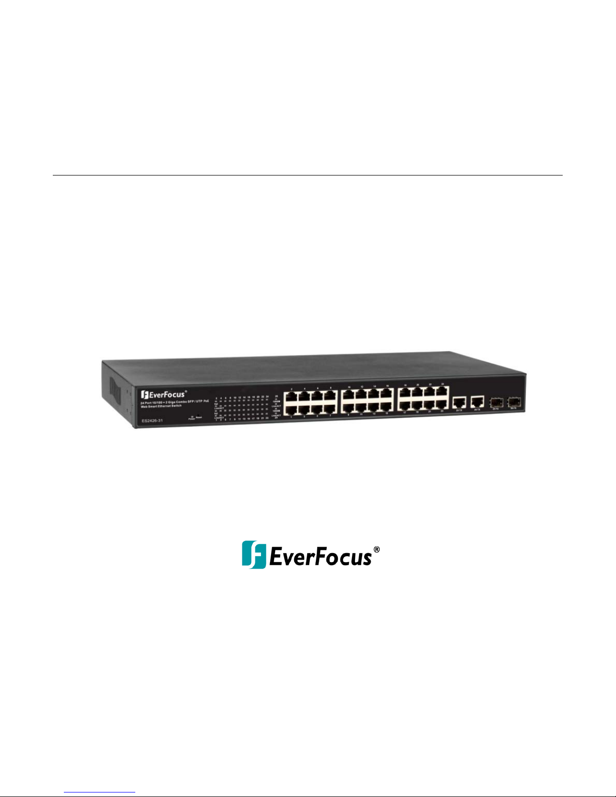
24-port 10/100M PoE + 2 Gigabit Copper/SFP Combo Rackmount
Web Smart PoE Switch
User’s Manual
Copyright © EverFocus Electronics Corp,
Release Date: September, 2013
Notice: This content is subject to be changed without notice.

EVERFOCUS ELECTRONICS CORPORATION
ES2426-31
User’s Manual
2013 EverFocus Electronics Corp
www.everfocus.com
All rights reserved. No part of the contents of this manual may be reproduced or transmitted in any form
or by any means without written permission of the Everfocus Electronics Corporation.
Release Date: September, 2013
QuickTime is a registered trademark of the Apple Computer, Inc.
Windows is a registered trademark of the Microsoft Corporation.
Linksys is a registered trademark of the Linksys Corporation.
D-Link is a registered trademark of the D-Link Corporation.
DynDNS is a registered trademark of the DynDNS.org Corporation.
Other product and company names mentioned herein may be the trademarks of their respective owners.

Safety Precautions
FCC Warning
This Equipment has been tested and found to comply with the limits for a Class-A digital device,
pursuant to Part 15 of the FCC rules. These limits are designed to provide reasonable protection
against harmful interference in a residential installation. This equipment generates, uses, and
can radiate radio frequency energy. It may cause harmful interference to radio communications
if the equipment is not installed and used in accordance with the instructions. However, there
is no guarantee that interference will not occur in a particular installation. If this equipment
does cause harmful interference to radio or television reception, which can be determined by
turning the equipment off and on, the user is encouraged to try to correct the interference by
one or more of the following measures:
Reorient or relocate the receiving antenna.
Increase the separation between the equipment and receiver.
Connect the equipment into an outlet on a circuit different from that to which the receiver is
connected.
Consult the dealer or an experienced radio/TV technician for help.
CE Mark Warning
This is a Class-A product. In a domestic environment this product may cause radio interference
in which case the user may be required to take adequate measures.
ii

TABLE OF CONTENTS
1. Introduction .................................................................................................................. 1
1.1 Product Overview .......................................................................................................... 1
1.2 Web Management Features .......................................................................................... 1
1.3 Specifications ................................................................................................................. 2
1.4 Mechanical ..................................................................................................................... 2
1.5 Performance .................................................................................................................. 3
1.6 Package Contents ........................................................................................................... 3
2. Hardware Description ................................................................................................... 4
2.1 Physical Dimensions/ Weight ........................................................................................ 4
2.2 Front Panel ..................................................................................................................... 4
2.3 LED Indicators ................................................................................................................ 4
2.4 Rear Panel ...................................................................................................................... 5
2.5 Hardware Installation .................................................................................................... 5
3. User Log In .................................................................................................................... 6
4. Administrator ............................................................................................................... 8
4.1 Authentication Configuration ........................................................................................ 8
4.2 System IP Configuration ................................................................................................. 8
4.3 System Status ................................................................................................................. 9
4.4 Load Default Setting ..................................................................................................... 10
4.5 Firmware Update ......................................................................................................... 11
4.6 Reboot Device .............................................................................................................. 11
5. Port Management ....................................................................................................... 12
5.1 Port Configuration ....................................................................................................... 12
5.2 Port Mirroring .............................................................................................................. 13
5.3 Bandwidth Control ....................................................................................................... 14
5.4 Broadcast Storm Control.............................................................................................. 14
5.5 PoE ............................................................................................................................... 15
6. VLAN Setting ............................................................................................................... 16
6.1 VLAN Mode .................................................................................................................. 16
6.2 VLAN Member .............................................................................................................. 17
6.3 Multi to 1 Setting ......................................................................................................... 19
7. Per Port Counter .................................................................................................. 20
7.1 Port Counter................................................................................................................. 20
iii

8. QoS Setting ................................................................................................................. 21
8.1 Priority Mode ............................................................................................................... 21
8.2 Port, 802.1p, IP/DS based ............................................................................................ 22
9. Security ....................................................................................................................... 23
9.1 MAC Address Binding ................................................................................................... 23
9.2 CP/UDP Filter ............................................................................................................... 24
10. Spanning Tree ............................................................................................................. 25
10.1 STP Bridge Settings ...................................................................................................... 25
10.2 STP Port Settings .......................................................................................................... 26
10.3 Loopback Detection Settings ....................................................................................... 27
11. Trunking ..................................................................................................................... 28
12. Backup /Recovery ....................................................................................................... 29
13. Miscellaneous ............................................................................................................. 30
14. Logout ........................................................................................................................ 31
15. Specification ............................................................................................................... 32
iv

ES2426-31
1
1
Chapter
1. Introduction
1.1 Product Overview
This switch provides 24 10/100Mbps RJ-45 ports and can support 2 Combo Gigabit RJ-45/SFP to
uplink. This web-smart switch includes auto-MDI/MDIX crossover detection function. 24 of those
ports are all built with PoE+ functionality, providing the ultimate choice in network flexibility. With
this added PoE feature, this switch is an ideal solution for building wireless, IP surveillance, and
VoIP networks.
It also provides port-based and 802.1Q tag VLAN function to provide better traffic management,
reduces latency, improve security and save bandwidth. This is also a cost-saving feature as it
reduces the need to add additional hardware to the network.
These 24 10/100Mbps RJ-45 support the IEEE 802.3at PoE protocol. Each port and transmit a
maximum power 30 watts. User can also enable or disable power supply on PoE ports from UI.
1.2 Web Management Features
• Port Management
Port Configuration
Port Mirroring
Bandwidth Control
Broadcast Strom Control
PoE On/Off Setting
• VLAN Setting
Port-based/ Tag-based
VLAN ID: 1~4094
• Trunking
Link Aggregation Setting
2 groups (1~4 port for each group)
• QoS Setting
Priority Mode
Class of Service Configuration
TCP/UDP Port-based
• Security Setting

ES2426-31
2
MAC address filtering
TCP/UDP Port filtering
• STP/RSTP
• Spanning Tree Protocol
• Backup Recovery Configuration
1.3 Specifications
• Standard
IEEE 802.3 10BaseT
IEEE 802.3u 100BaseTX
IEEE 802.ab 1000BaseT
IEEE 802.3z 1000BaseSX/LX
IEEE 802.3x Full-duplex and Flow Control
IEEE 802.af PoE
IEEE 802.at PoE
IEEE 802.3ad Link Aggregation
IEEE 802.1d Spanning tree protocol
IEEE 802.1w Rapid Spanning tree protocol
IEEE 802.1x Port-based Network Access Control
IEEE 802.1Q VLAN
IEEE 802.1p Class of Service
• Number of Port
24-port 10/100BaseTX with PoE
2-port Combo Gigabit uplink (RJ-45/SFP)
1.4 Mechanical
• LED Indicator
Per Port: Link/ Act
PoE Port: Act/Status
Per Unit: Power
• Power Consumption: 400Watts (Max)
• Power Input: 100~240V/AC, 50~60HZ
• Power Output: 48V/DC per Port Output – 30W Max per Port
• Product Dimensions/ Weight
44 × 440 × 332 mm (H × W ×D) / 4.7kg
ES2426-31
3
1.5 Performance
• MAC Address: 4K
• Buffer Memory: 2.75Mb
• Transmission Method: Store and Forward
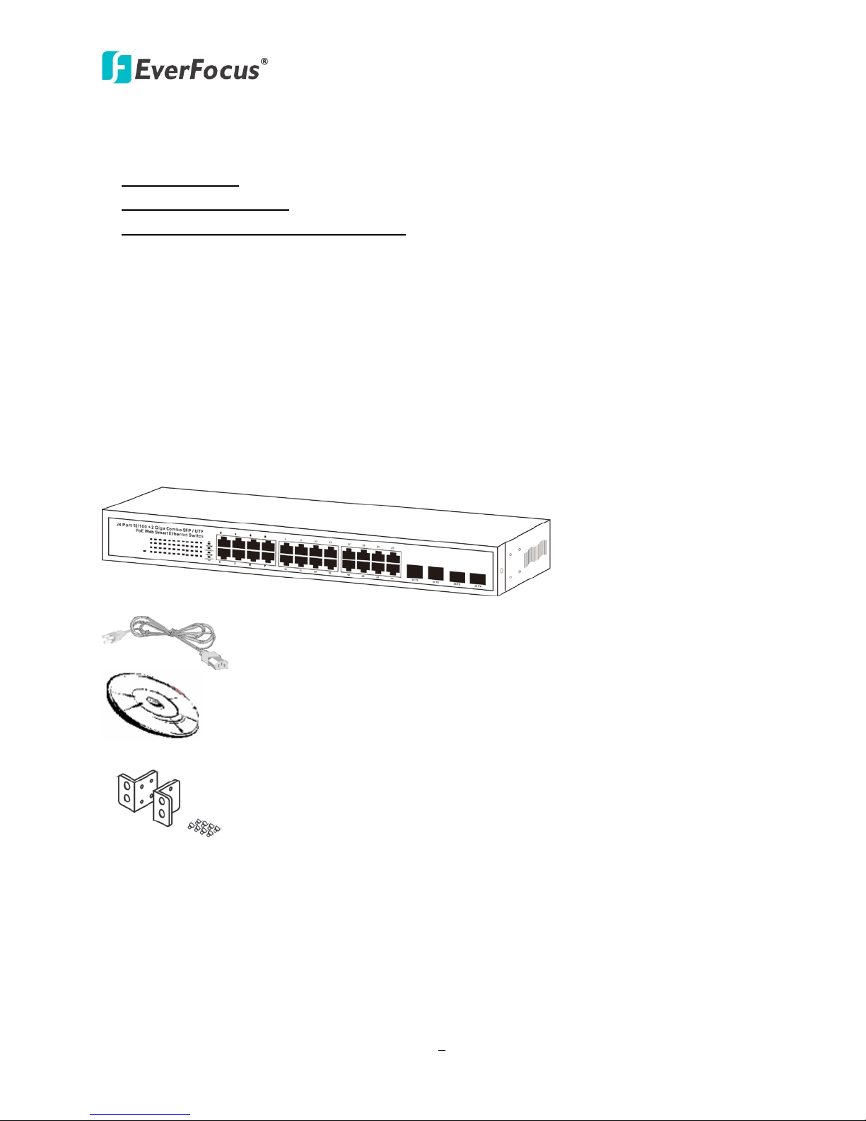
1.6 Package Contents
Before you start to install this switch, please verify your package that contains the following
items:
1. One Fast Ethernet PoE Switch
2. One Power Cord
3. One User Manual
4. One pair Rack-mount kit + 8 Screws
ES2426-31
4
LED
Status
Description
No. Of LED
Power
On
Power on
Power
On
Link 1000Mbps
off
Link 10/100Mbps
Link/ ACT
On
Link
26 (1~26)
2
LED
Combo Uplink
RJ-45 Port
Chapter
2. Hardware Description
This section mainly describes the hardware of the 8 PoE port Ethernet Combo Web-Smart Switch
and gives a physical and functional overview on the certain switch.
2.1 Physical Dimensions/ Weight
44 × 440 × 332 mm (H × W ×D) / 4.7kg
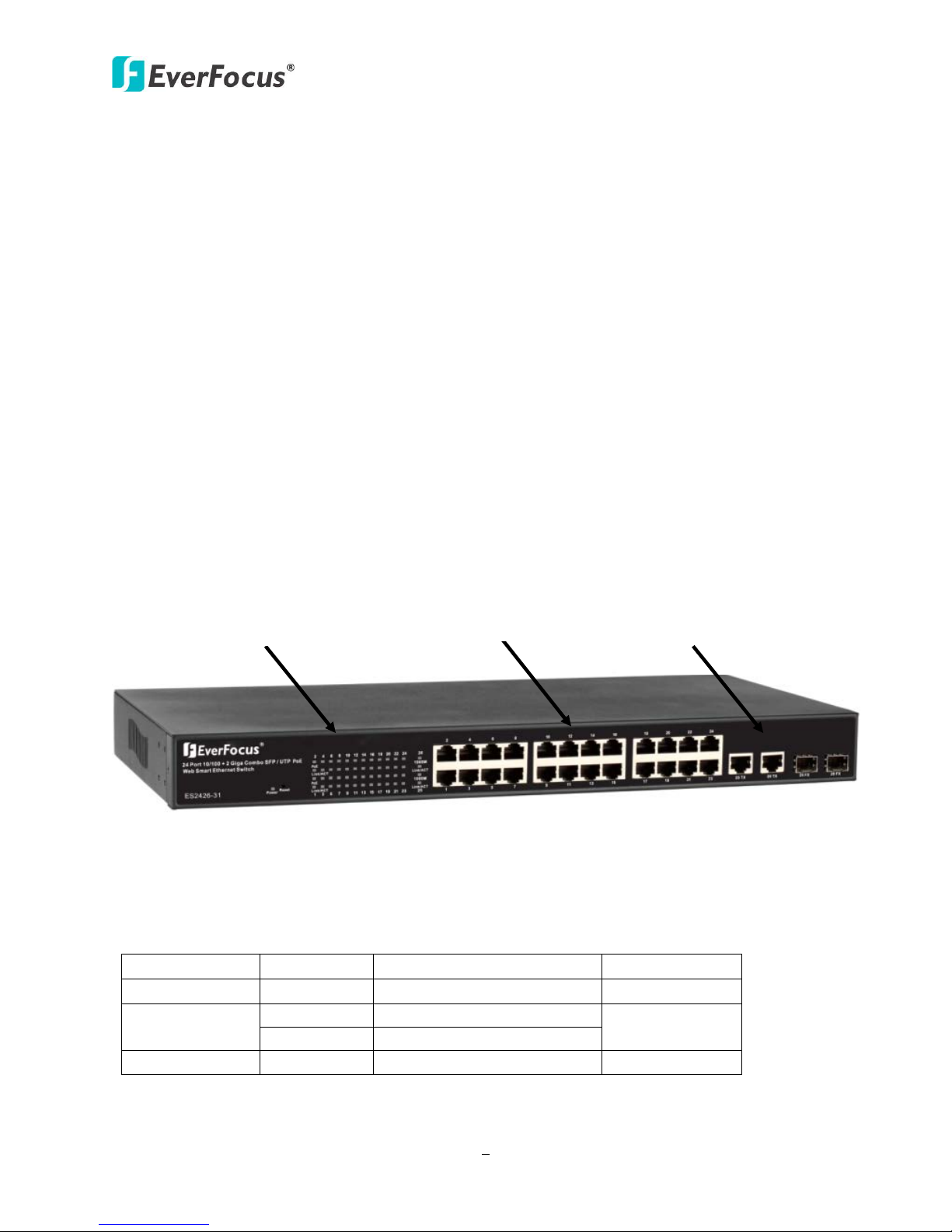
2.2 Front Panel
The front panel of the web smart switch consists of 24 10/100Base-TX RJ-45 ports and 2 combo
gigabit uplink RJ-45/SFP ports. The LED Indicators are also located on the front panel.
RJ-45/SFP Port
2.3 LED Indicators
The LED Indicators present real-time information of systematic operation status. The following
table provides description of LED status and their meaning.
1000M
2 (25~26)
ES2426-31
5
Flashing
Data activating
26 (1~26)
Port is linked to Power
No Power Device is
PoE
On
Off
Device
connected
24 (1~24)
24 (1~24)
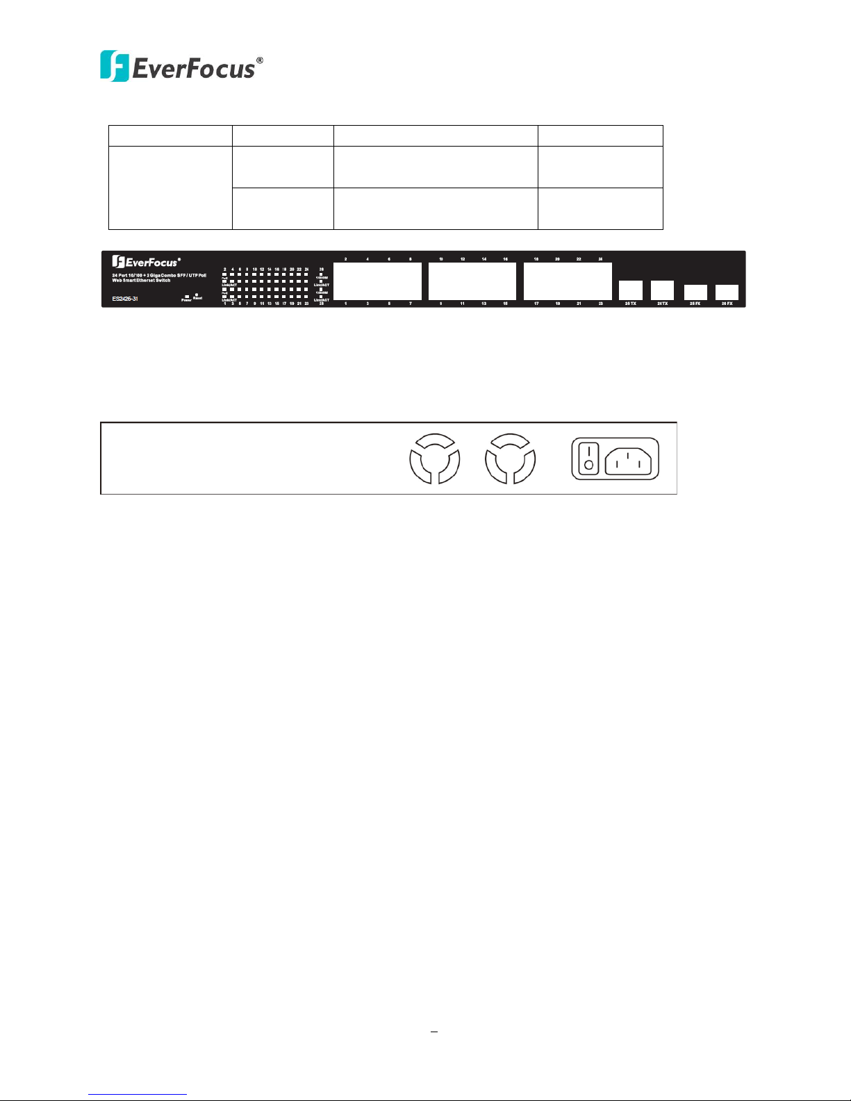
2.4 Rear Panel
The 3-pronged power plug is placed at the rear panel of the switch right side shown as below.
2.5 Hardware Installation
Set the switch on a large flat space with a power socket close by. The flat space should be clean,
smooth, level and sturdy. Make sure there is enough clearance around the switch to allow
attachment of cables, power cord and allow air circulation. The last, use twisted pair cable to
connect this switch to your PC then user could start to operate the switch.
ES2426-31
6
3
Chapter
3. User Log In
This part instructs user how to set up and manage the switch through the web user interface.
Please follow the description to understand the procedure.
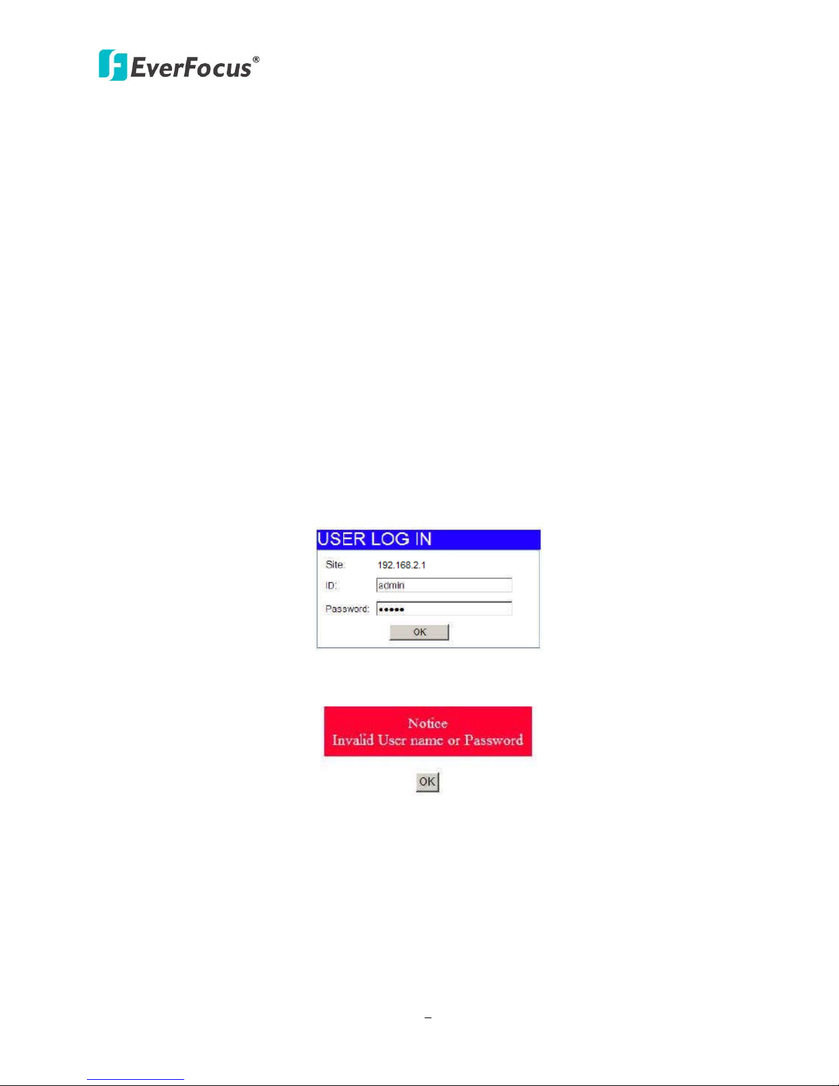
At the first, open the web browser, and go to 192.168.2.1 site then the user will see the login
screen. Key in the password to pass the authentication then clicks the OK. The log in process is
completed and comes out the sign “Password successfully entered”.
Log in
ID: admin
Password: admin
※Note: It will show error message if you key in wrong user name or password.
Figure 1-1
Figure 1-2
7
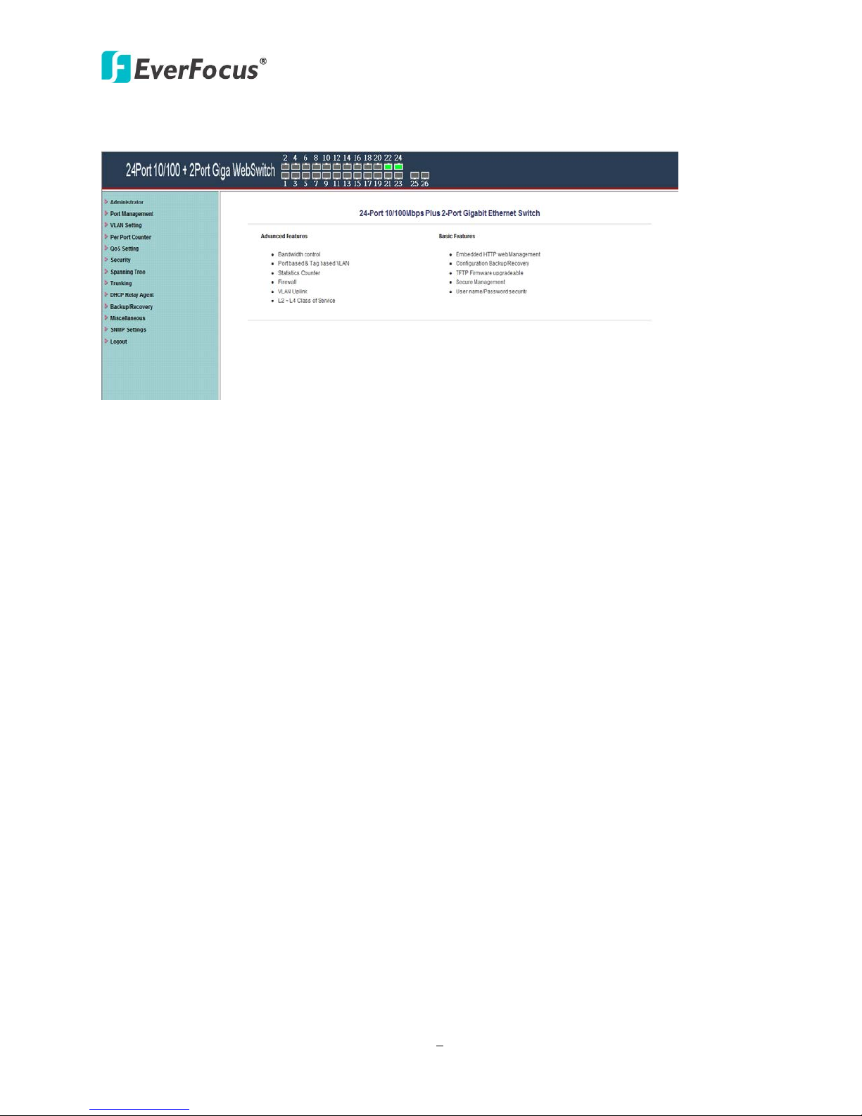
Main Page
ES2426-31
Figure 1-3
 Loading...