

EverFocus ES0802-41 User Manual

ES0802-41
8-port 10/100/1000M PoE+ Web Smart Gigabit Ethernet Switch
User’s Manual
Copyright © EverFocus Electronics Corp,
Release Date: September, 2013
Notice: This content is subject to be changed without notice.

EVERFOCUS ELECTRONICS CORPORATION
PoE Switch
User’s Manual
2013 EverFocus Electronics Corp
www.everfocus.com
All rights reserved. No part of the contents of this manual may be reproduced or transmitted in any form
or by any means without written permission of the Everfocus Electronics Corporation.
Release Date: September, 2013
QuickTime is a registered trademark of the Apple Computer, Inc.
Windows is a registered trademark of the Microsoft Corporation.
Linksys is a registered trademark of the Linksys Corporation.
D-Link is a registered trademark of the D-Link Corporation.
DynDNS is a registered trademark of the DynDNS.org Corporation.
Other product and company names mentioned herein may be the trademarks of their respective owners.

Safety Precautions
FCC Warning
This Equipment has been tested and found to comply with the limits for a Class-A
digital device, pursuant to Part 15 of the FCC rules. These limits are designed to
provide reasonable protection against harmful interference in a residential
installation. This equipment generates, uses, and can radiate radio frequency energy.
It may cause harmful interference to radio communications if the equipment is not
installed and used in accordance with the instructions. However, there is no
guarantee that interference will not occur in a particular installation. If this
equipment does cause harmful interference to radio or television reception, which
can be determined by turning the equipment off and on, the user is encouraged to
try to correct the interference by one or more of the following measures:
Reorient or relocate the receiving antenna.
Increase the separation between the equipment and receiver.
Connect the equipment into an outlet on a circuit different from that to which the
receiver is connected.
Consult the dealer or an experienced radio/TV technician for help.
CE Mark Warning
This is a Class-A product. In a domestic environment this product may cause radio
interference in which case the user may be required to take adequate measures.

Table of Contents
Table of Contents .................................................................................................. 5
1. Introduction .................................................................................................. 1
1.1 Product Overview................................................................................................. 1
1.2 Web Management Features ................................................................................ 1
1.3 Specifications ....................................................................................................... 2
1.4 Mechanical ........................................................................................................... 2
1.5 Performance ......................................................................................................... 3
1.6 Package Contents ................................................................................................. 3
2. Hardware Description .................................................................................... 4
2.1 Physical Dimensions/ Weight ............................................................................... 4
Front Panel ............................................................................................................. 4
LED Indicators ......................................................................................................... 4
Rear Panel .............................................................................................................. 5
Hardware Installation ............................................................................................. 5
3. Software Description ..................................................................................... 6
3.1 Configuration ....................................................................................................... 7
System .................................................................................................................... 7
Ports ....................................................................................................................... 9
VLAN ..................................................................................................................... 10
Aggregation .......................................................................................................... 13
LACP ..................................................................................................................... 13
RSTP ...................................................................................................................... 14
IGMP Snooping .................................................................................................... 17
Mirroring .............................................................................................................. 17
Quality of Service (QoS) ....................................................................................... 19
PoE (Power over Ethernet) Configuration ............................................................ 22
Storm Control ....................................................................................................... 23
3.2 Monitoring ......................................................................................................... 24
Statistic Overview ................................................................................................ 24
Detailed Statics..................................................................................................... 25
LACP Status .......................................................................................................... 25
RSTP Status ........................................................................................................... 26
IGMP Status .......................................................................................................... 28
VeriPHY ................................................................................................................. 28

Ping ....................................................................................................................... 30
3.3 Maintenance ...................................................................................................... 32
Warm Restart ....................................................................................................... 32
Factory Default ..................................................................................................... 32
Software upload ................................................................................................... 33
Configuration File Transfer ................................................................................... 33
Logout .................................................................................................................. 33
3.4 Reset button for the factory default setting ...................................................... 34

PoE Switch
1
1. Introduction
1.1 Product Overview
This switch is a Web Smart Switch equipped with 8-ports 10/100/1000BaseT(X)
with 8 PoE+ Ports. It is designed for easy installation and high performance in an
environment where traffic is on the network and the number of users increased
continuously. The compact rigid 19” rack-mount size is specifically designed for
small to medium workgroups. It can be installed where space is limited; moreover,
it provides smooth network migration and is easy to upgrade the network capacity.
In addition, the switch features comprehensive and useful functions, such as: QoS
(Quality of Service), Spanning Tree, VLAN, Power over Ethernet (PoE), Link
Aggregation, SNMP/RMON, IGMP Snooping capability via the intelligent software.
It is suitable for both metro-LAN and office application.
1.2 Web Management Features
Configuration
System
Ports
VLANs
Aggregation
LACP
RSTP
IGMP Snooping
Mirroring
Quality of Service
Power over Ethernet
Storm Control
Monitoring

PoE Switch
2
Statistics Overview
Detailed Statistics
LACP Status
RSTP Status
IGMP Status
VeriPHY
Ping
Maintenance
Warm Restart
Factory Default
Software Upload
Configuration File Transfer
Logout
1.3 Specifications
Standard
IEEE 802.3 10BaseT
IEEE 802.3u 100BaseTX
IEEE 802.3ab 1000BaseT
IEEE 802.3af PoE
IEEE 802.3at PoE+
IEEE 802.3z 1000BaseSX/LX
IEEE 802.3x Full-duplex Flow Control
IEEE 802.3ad Link Aggregation
IEEE 802.1Q VLAN
IEEE 802.1d Spanning tree protocol
IEEE 802.1w Rapid Spanning tree protocol
IEEE 802.1p QoS
Number of Port
8-port 10/100/1000BaseT(X) with 8-port PoE+
1.4 Mechanical
LED Indicator

PoE Switch
3
Port 1~8: Link/ Act, 1000M.
Port 1~8: PoE
Per Unit: Power
Power Consumption: 130 Watts (Max), 30 Watts per port
Power Input: 100~240V/AC, 50~60HZ
Product Dimensions/ Weight: 266 × 160 × 44 mm (L × W ×H) / 1.6kg
1.5 Performance
MAC Address & Multicast group: 8K
Buffer Memory: 176 KB
Jumbo Frames: 9.6K
Transmission Method: Store and Forward
1.6 Package Contents
Before you start to install this switch, please verify your package that contains the
following items:
One PoE Gigabit Ethernet Switch
One AC Power Cord
One User Manual
PoE Switch
4
2. Hardware Description
This part primarily presents hardware of this switch, physical dimensions and
functional overview would be described.
2.1 Physical Dimensions/ Weight
266 × 160 × 44 mm (L × W ×H) / 1.6kg
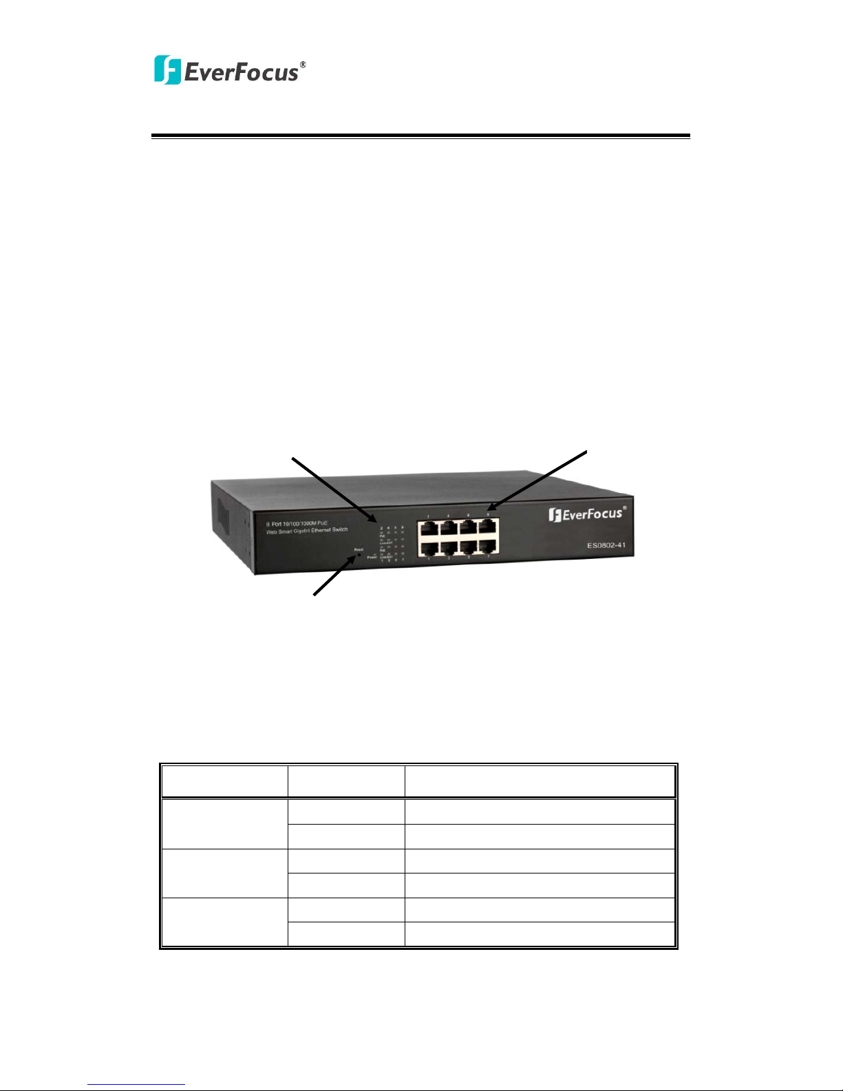
Front Panel
The front Panel of the Web Smart Switch consists of 8 gigabit RJ-45 ports+2 gigabit
SFP open slot. The LED Indicators are also located on the front panel.
LED Indicators
The LED Indicators present real-time information of systematic operation status. The
following table provides description of LED status and their meaning.
Table 1 -1 LED Indicators
LED Status Description
Power
On Power is on.
Off Power is off.
Link/ACT
Port 1~8
On 10/100/1000 Link is connected
Off 10/100/1000 Link is disconnected
PoE
Port 1~8
On providing the power
off not providing the power
LED Display
RJ-45 Port
Reset

PoE Switch
5
Rear Panel
The 3-pronged power plug is placed at the rear panel of the switch right side shown
as below.
Hardware Installation
Set the switch on a large flat space with a power socket close by. The flat space
should be clean, smooth, level and sturdy. Make sure there is enough clearance
around the switch to allow attachment of cables, power cord and allow air
circulation. The last, use twisted pair cable to connect this switch to your PC then
user could start to operate the switch.
PoE Switch
6
3. Software Description
This part instructs user how to set up and manage the switch through the web user
interface. Please follow the description to understand the procedure.
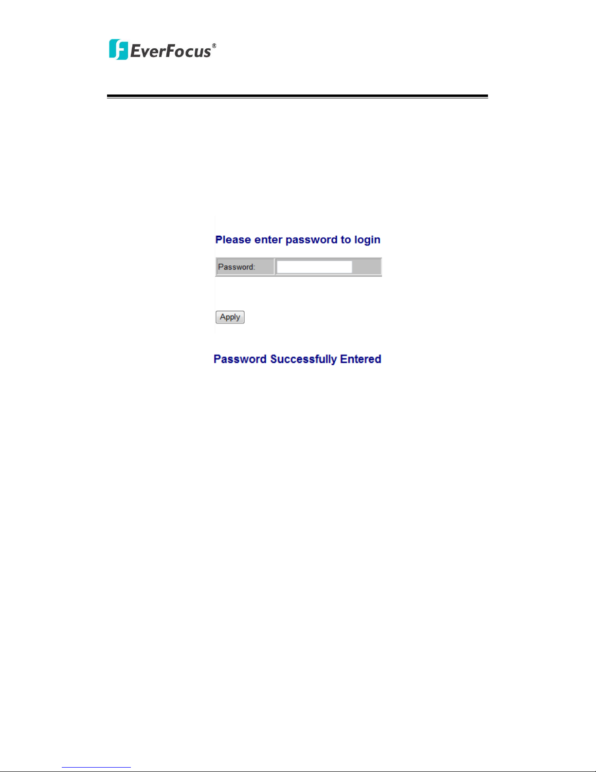
At the first, open the web browser, and go to 192.168.2.1 site then the user will see
the login screen. Just clicks the Apply then the login process is completed and comes
out the sign “Password successfully entered”.
Figure 1-1
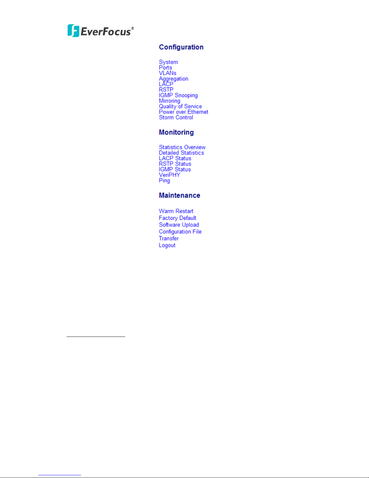
After the user login, the right side of website shows all functions as Fig. 1-2.
PoE Switch
7
Figure 1-2
3.1 Configuration
System
System Configuration
This page shows system configuration information. User can configure lots of
information as Fig. 1-3:
 Loading...