

Page 1
Instruction Manual
EERRSS--44
44 CChhaannnneell VViiddeeoo SSeerrvveerr // RReeccoorrddeer
r
Page 2

All rights reserved. No part of the contents of this manual may be reproduce d or transmitted in any form or by
any means without written permiss ion of th e Ev erfocus El ectronics Corporation.
Release Date: Feb. 2010
QuickTime is a registered trademark of the Apple Computer, Inc.
iPhone is a registered trademark of the Apple Computer, Inc.
RealPlayer is a registered trademark of the RealNetworks, Inc.
Windows is a registered trademark of the Microsoft Corporation.
Linksys is a registered trademark of the Linksys Corporation.
D-Link is a registered trademark of the D-Link Corporation.
DynDNS is a registered trademark of the DynDNS.org Corporation.
Other product and company names mentioned herein may be the trademarks of their respective owners.
Page 3
Y
Safety Precautions
• To avoid any damage, please consider the following safety warnings:
• Never place the device near to heaters, furnaces, other heat sources or under direct solar irradiation.
• Operate the device only in locations providing the tolerable operating temperature range 0°C~40°C/32°F ~ +104°F.
• Make sure that the device‘s ventilation slots are not covered or sheeted.
• For cleaning, make sure the device is plugged off and only use a damp cloth without acid detergent.
• Install the device only in dry and dustproof surroundings. Protect the device against any liquid‘s penetration.
• Avoid the penetration of any artefacts, e.g. through ventilation slots.
• Do not attempt to disassemble the appliance. To prevent electric shock, do not remove screws or covers. There are no userserviceable parts inside. Contact qualified service personnel for maintenance. Handle the appliance with care. Do not strike
or shake, as this may damage the appliance.
• Do not operate appliance with other than specified power supplies.
• Avoid any affection of the device through vibrations or mechanical shock at the recorder‘s installation location.
• Avoid to power off the device during playback or recording operation.
ATTENTION! This is a class A product which may cause radio interference in a domestic environment; in this case, the user may be
urged to take adequate measures.
Federal Communication Commission Interference Statement
This equipment has been tested and found to comply with the limits for a Class B digital device, pursuant to Part 15 of the FCC Rules.
These limits are designed to provide reasonable protection against harmful interference in a residential installation. This equipment
generates, uses and can radiate radio frequency energy and, if not installed and used in accordance with the instructions, may cause
harmful interference to radio communications. However, th ere is no guarantee that interference will not oc cur in a particular installation.
If this equipment does cause harmful interference to radio or television reception, which can be determined by turning the equipment off
and on, the user is encouraged to try to correct the interference by one of the following measures :
•Reorient or relocate the receiving antenna.
•Increase the separation between the equipment and receiver.
•Connect the equipment into an outlet on a circuit different from that to which the receiver is connected.
•Consult the dealer or an experienced radio/TV technician for help.
FCC Caution: Any changes or modifications not expressly approved by the party responsible for compliance could void the users’
authority to operate this equipment.
This Product is RoHS compliant.
WEEE
our EverFocus product is designed
and manufactured with high quality
materials and components which can
be recycled and reused.
This symbol means that electrical and
electronic equipment, at their end-oflife, should be disposed of separately
from your household waste.
Please, dispose of this equipment at
your local community waste
collection/recycling centre.
In the European Union there are
separate collection systems for used
electrical and electronic product.
Please, help us to conserve the
environment we live in!
Ihr EverFocus Produkt wurde
entwickelt und hergestellt mit qualitativ
hochwertigen Materialien und
Komponenten, die recycelt und wieder
verwendet werden können.
Dieses Symbol bedeutet, dass
elektrische und elektronische Gerä te
am Ende ihrer Nutzungsdauer vom
Hausmüll getrennt entsorgt werden
sollen.
Bitte entsorgen Sie dieses Gerät bei
Ihrer örtlichen kommunalen
Sammelstelle oder im Recycling Centre.
Helfen Sie uns bitte, die Umwelt zu
erhalten, in der wir leben
!
The information in this manual was current upon publication. The manufacturer reserves the right to revise and improve his products.
Therefore, all specifications are subject to change without prior notice. Misprints reserved.
Please read this manual carefully before installing and using this unit. Be sure to keep it handy for later reference.
ii
Page 4

TABLE OF CONTENTS
1 PRODUCT OVERVIEW.............................................. .... ........ .... ..... .... ........ ..... .... .... ........ ..... .... ........ .....1
1.1 FEATURES.................................. ......................................................................................................1
1.2 PACKAGE CONTENTS....................................................................................................................1
1.3 OPTIONAL ACCESSORIES......................................... ....................................................................1
1.4 SPECIFICATIONS.............................................................................................................................2
1.5 FRONT PANEL................................................................................................................................. .3
1.6 REAR PANEL CONNECTORS................................................................................... ......................4
2 INSTALLATION......................................... .............................................................................................5
2.1 VIDEO INPUTS/OUTPUTS INSTALLATION....................................................................................5
2.2 AUDIO INSTALLATION.....................................................................................................................6
2.3 ALARM CONTACTS INSTALLATION ............................................................................ ..................7
2.3.1 Alarm Input Contacts................. ..... ........ .... ..... ........ .... ..... ........ .... .... ......... .... .... ......... .... .... .........7
2.3.2 Alarm Output Relay..................................................... .... ......... .... .... ......... .... .... ......... .... .... .........7
2.4 RS-485 KEYBOARD / PTZ INSTALLATION.....................................................................................8
2.4.1 General RS-485 bus installation........................................................................ ..........................8
2.4.2 RS-485 terminal pin assignment............................................................... ..................................9
2.4.3 Speed Dome Installation.............................................................................................................9
2.5 USB-MOUSE INSTALLATION......................................................................................... ...............10
2.6 MO N I T O R C O N N EC T I O N........................................................................ .............................................11
2.7 NETWORK CONNECTION.................................................................... ......... .... .... ......... .... .... .......11
2.7.1 Direct PC Connection through Crossover Network Cable........................................................11
2.7.2 Network Connection through Patch Cable..................................................................... ...........12
2.8 FINAL INSTALL PROCESS............................................................................................................12
3 CONFIGURATION VIA NETWORK................................................ .....................................................13
3.1 IP-SETUP VIA NETWORK WITH IP-UTILITY..................................................................... ...........13
3.2 CONNECTING TO ERS-4...............................................................................................................14
3.3 BROWSER SECURITY SETTING..................................................................................................15
3.3.1 Installing ActiveX controls............................................................. .... ......... .... .... .... ......... .... .... ...15
3.3.2 Enabling ActiveX Controls.........................................................................................................17
3.4 REMOTE LIVE SCREEN........................................................... ........ .... .... ......... .... .... ......... .... .......20
3.5 REMOTE SETUP - EXPRESS.................................................................... ....................................22
3.6 REMOTE SETUP - CAMERA.........................................................................................................25
3.6.1 Camera: Basic settings......................................................... .....................................................25
3.6.2 Camera: Video Adjust.............................................. ................................................... ...............27
3.6.3 Camera: Motion....................................................... ................................................... ...............28
3.6.4 Camera: Video Loss..................................................................................................................30
3.7 REMOTE SETUP: RECORD ..........................................................................................................32
3.7.1 Record: Record............................................................ ......... .... ........ .... ..... ........ .... ..... ...............32
3.8 REMOTE SETUP: ALARM.......................................................................... ....................................33
3.8.1 Alarm: Alarm................................................................................. .............................................33
3.8.2 Alarm: Event.......................... ....................................................................................................35
iii
Page 5

3.8.2.1 Event: Fan failure......................................................................................................................35
3.8.2.2 Event: HD Temperature............................................................................................................36
3.8.2.3 Event: HD failure.......................................................................................................................37
3.8.2.4 Event: HDD Full.........................................................................................................................38
3.8.2.5 Event: HD Off............................................................................................................................39
3.8.2.6 Event: Power Loss ....................................................................................................................40
3.8.2.7 Event: Network Loss ......................................................................................... ........................41
3.9 REMOTE SETUP: SCHEDULE............................................................. .........................................42
3.9.1 Schedule: Express Setup............................................................. .............................................42
3.9.2 Schedule: Holidays....................................................................................................................44
3.9.3 Schedule: Schedule...................................................................................................................45
3.9.4 Schedule: Alarm Action.............................................................................................................48
3.10 REMOTE SETUP: NETWORK........................................................................................................50
3.10.1 Network: LAN............................................................................ .... .... ......... .... .... ......... .... ...........50
3.10.2 Network: Email...................................................................... .... ........ .... ..... ........ .... ..... ...............52
3.10.3 Network: DDNS........................................................................ .... ......... .... .... ........ ..... .... .... .......53
3.10.3.1 EverFocus DDNS......................... .... .... ......... .... .... .... ......... .... .... ......... .... .... .... ......... .... ...........53
3.10.3.2 Dyndns DDNS.............................. .... .... ......... .... .... .... ......... .... .... ......... .... .... ........ ..... ...............55
3.10.4 Network: Alarm Server ........................................ ........ .... ..... ........ .... ..... ........ .... .... ......... .... .... ...56
3.11 REMOTE SETUP: DISK..................................................................................................................57
3.12 REMOTE SETUP: DISPLAY...................................................................... .....................................58
3.12.1 Monitor OSD.......................................................................................................... ....................58
3.12.2 Main M/T SEQ: Sequence............................................................................. .... ......... .... .... .......59
3.13 REMOTE SETUP: SYSTEM...........................................................................................................60
3.13.1
System: Date / Time......................................................... .................................................. .......60
3.13.2 System: Daylight Saving............................................................................................................61
3.13.3 System: User.................................. ...........................................................................................62
3.13.3.1 User right definition .................................................................................................................62
3.13.3.2 Edit user account..................................................................................... ........ .... ....................63
3.13.3.3 Add user account ........................................................................... .........................................64
3.13.3.4 Delete user account................................................................................................................64
3.13.4 System: I/O Control...................................................................................................................65
3.13.5 System: Miscellaneous....................................................................................................... .......66
4 NETWORK OPERATION .....................................................................................................................67
4.1 LIVE SCREEN CONTROLS................................................................... .........................................67
4.2 VIEW MODES.................................................................................................................................68
4.2.1 Full Screen.................................................................................................................................68
4.2.2 4 x Screen..................................................................................................................................68
4.2.3 Frameless Video Screen...........................................................................................................68
4.3 BIDIRECTIONAL AUDIO................................................... ..............................................................68
4.4 PLAYBACK SEARCH......................................................................................................................69
4.4.1 Event Search.............................................................................................................................69
4.4.2 Time / Date Search....................................................................................................................72
4.5 VIDEO COPY / EXPORT..................... .... ........ ..... .... .... .... ......... .... .... .... .... ......... .... .... ..... .... ....... . ...73
4.5.1 Export File Evaluation with EFPlayer Software.........................................................................74
4.6 PTZ CONTROL................................ ...............................................................................................75
4.7
INFO............................................................................................................................................. ...76
4.7.1 Info: System.......................................................................................... ..... ........ .... ..... ........ .......76
iv
Page 6

4.7.2 Info: Log........................................................... .... .... ........ ..... ........ .... ..... ........ .... .... ....................77
4.7.2.1 View Log.................................................................. ................................................... ...............78
4.7.2.2 Delete Log.......................................... .......................................................................................78
4.7.2.3 Export LOG............................................................................... .................................................78
5 APPENDIX A: HDD ASSEMBLING .....................................................................................................79
5.1 OPEN ERS-4 HOUSING.................................................................... .............................................80
5.2 MOUNTING HDD BRACKETS........................................................................................................81
5.3 ASSEMBLING COOLER FAN.........................................................................................................82
5.4 SATA AND POWER CABLE INSTALLATION................................................................................83
5.5 HDD MOUNTING IN HOUSING......................................................................................................84
5.6 CLOSING ERS-4 HOUSING.................................................................. .........................................85
6 APPENDIX B: 3GPP MOBILE PHONE STREAMING.........................................................................86
6.1 GENERAL REQUIREMENTS....................................... ..................................................................86
6.2 APPLE IPHONE..............................................................................................................................86
6.3 OTHER MOBILE PHONES.............................................................................................................87
7 APPENDIX C: NETWORKING............................................................ .................................................88
7.1 NETWORKING OVERVIEW...................................................... .... .... ........ ..... .... ........ .... ..... ........ ...88
7.1.1 Introduction to TCP/IP................................ ...............................................................................88
7.1.2 Subnet Masks....................................................................... .....................................................88
7.1.3 Gateway Address............................................ ........ .... ..... ........ .... .... .... ......... .... .... ......... .... .......88
7.1.4 Virtual Ports.................................... .... .... ......... .... .... ........ ..... .... ........ .... ......... .... .... ....................88
7.2 WHAT IS YOUR NETWORK SETUP?...........................................................................................90
7.2.1 Simple One to One Connection...................................................................................... ...........90
7.2.2 Direct High Speed Modem Connection.............................................................................. .......95
7.2.3 Router or LAN Connection........................................................... ......... .... .... ........ ..... .... .... .......97
7.3 LINKSYS & D-LINK PORT FORWARDING....................................................................................99
7.3.1 Linksys Port Forwarding............................................................................................................99
7.3.2 D-Link Port Forwarding............................................................................................................102
8 APPENDIX D: TIMING OF ALARM MODES.....................................................................................104
9 APPENDIX E: CHANGING RULE FOR EXPRESS SETUP..............................................................107
10 APPENDIX E: LOCAL SETUP AT ERS-4 ................................................................................ .........109
10.1 OPEN CONFIGURATION MENU.................................................................................................109
10.2 EXPRESS.......................................................................................................................................109
10.3 CA M E R A S E T TI N G............ .............................................. .......................................... ......................112
10.3.1 Basic Setting........................................................ ....................................................................112
10.3.2 Video Adjust.............................................................................................................................114
10.3.3 Motion......................................................................................................................................115
10.3.4 Video Loss...............................................................................................................................117
10.4 RECORD SETTING .................................................................................... ..................................118
10.5 ALARM & EVENT SETTING............................. ............................................................................119
10.5.1 Alarm........................................................... .............................................................................119
10.5.2 Event........................................................................................................................................121
10.6 SC H E D U L E SE T T I N G.......................................................... .......................................... ..................128
10.6.1 Express Setup.......................................................................... .............................................. .128
v
Page 7

10.6.2 Holidays....................................................................... ....................................................... .....129
10.6.3 Schedule..................................................................................................................................130
10.6.4 Alarm Action ..................................................................................... ..... ........ .... .... ..................134
10.7 NETWORK....................................................................................................................................138
10.7.1 LAN..........................................................................................................................................138
10.7.2 EMAIL........................ ..............................................................................................................139
10.7.3 DDNS.......................................................................................................................................139
10.7.4 Alarm Server......................................................................... .... .... ......... .... .... ........ ..... .............142
10.8 DISK SETTING..............................................................................................................................143
10.9 DISPLAY SETTING.................................................................... ........ .... ......... .... .... ......... .... .... .....144
10.9.1 Monitor OSD..... .......................................................................................................................144
10.9.2 Main M/T SEQ................................................. ........ .... .... ......... .... ........ ..... .... ........ ..... .... .........145
10.10 SYSTEM SETTING....................................................................................................................146
10.10.1 Date/Time.............................................................................................................................146
10.10.2 Daylight Saving................................................................................................... ..................147
10.10.3 User.............................................................. ........................................................................148
10.10.4 I/O Control.............................................................................................................................150
10.10.5 Misc.......................................................................................................................................151
10.11 INFORMATION....................................................... ....................................................................152
10.11.1 System..................................................................................................................................152
10.11.2
Log........................................................................................................................................153
vi
Page 8

ERS-4 Instruction Manual
1 PRODUCT O VERVIEW
The ERS-4 is a 4 channel video server with local recording function for CCTV applications.
With the optional build-in HDD the ERS-4 is the ideal device for network operated CCTV systems with local
recording and low usage of systems network bandwidth.
The efficient H.264 compression with newest codec - technology allows fast network video streaming in
excellent quality, furthermore an efficient usage of Hard Disk capacity at local recording.
The ERS-4 provides live and playback evaluation via network. Live view and setup menu are also
accessible at local monitor, operated by mouse.
1.1 FEATURES
• H.264 Compression format
• User friendly GUI with graphical icons and visual ind i cators
• Setup menu local (mouse, local monitor) or via network (Browser, CMS)
• Express Setup: by entering key parameters in EXPRESS menu the ERS-4 is ready for operatio n
within a minute
• Audio recording capabilities
• Optional 1 inter nal SATA HDD
• Multi-language support
1.2 P ACKAGE CONTENTS
ERS-4 video server x1
Quick Installation Guide x1
User’s Manual Disk x1
AC Adapter and Power Cord x1
1.3 OPTIONAL ACCESSORIES
ERS-HDMK: ERS-4 Hard Disk mounting kit for installing 3.5" SATA HDD to ERS-4-NH
1
Page 9

1.4 SPECIFICA TIONS
ERS-4 Instruction Manual
Physical
352x288: 100 IPS PAL / 120 IPS NTSC
Recording Rate/Resolution
Playback and Streaming
Rate/Resolution
Video Input
Monitor output
Audio Input/Output
Alarm In 4 x N.O./N.C. , screw terminal connector
Alarm Out 1 x relay out N.O./N.C. , screw terminal connector
RS-485 1 x, screw terminal connector
Network interface
USB
Status LED Power, Alarm, HDD activity, Network traffic
Clock Internal Real Time Clock, NTP synchronisation option
Power Source 12VDC with external power supply 100~240 VAC / 50/60 Hz
Dimensions (W x D x H) 320 x 208.9 x 54.3 mm / 12.6" x 8.2" x 2.1"
Temperature 0°C~40°C / 32°F~104°F (20~80% humidity)
Functional
OS Embedded Linux
704x288: 100 IPS PAL / 120 IPS NTSC
704x576: 50 IPS PAL / 60 IPS NTSC
352x288: up to 100 IPS PAL / 120 IPS NTSC
704x288: up to 100 IPS PAL / 120 IPS NTSC
704x576: up to 50 IPS PAL / 60 IPS NTSC
depending on network conditions
4 x 1 Vpp FBAS, BNC, 75 Ohm termination
1 x 1 Vpp FBAS, BNC at 75 Ohm
1 x VGA ( resolution 800x600@60 Hz)
Input: 1 x Line In, 1 V max. / 1 KOhm, RCA socket
Output: 1 x Line Out 1 V max. at 1 KOhm, RCA socket
100 BASE-T, 8P8C / RJ45 socket
1x USB 2.0 on Back Panel (for USB - Mouse)
1x USB 2.0 on Front Panel (for service purpose)
Video Compression H.264
User Interface GUI(Graphical User Interface)
Operation Simultaneous network Live/Playback operation and local Recording
Recording Mode Manual, Schedule and Event
Playback Search By Date/Time or Event
Video Pause Yes
Video Loss Detection Yes
Motion Detection Yes
Event Log Yes
Schedule Setting Support Express and Advanced Schedule Setting
User Access 3 Levels of User Access Supp ort
PTZ Protocols EverFocus, Pelco-D, Pelco-P, Samsung El., Transparent
2
Page 10

1.5 FRONT PANEL
The front panel provides 1 USB port and the status LEDs.
ERS-4 Instruction Manual
USB-port
Figure 1-1 Front Panel
USB port: USB 2.0 interface PC - mouse or service purpose .
Status LED: POWER: LED ON indicates Power ON.
ALARM: LED ON indicates Alarm active.
HDD: LED flashes in case of HDD activity.
Net: LED flashes in case of Network activity.
Status - LED
3
Page 11

ERS-4 Instruction Manual
1.6 REAR P A NEL CONNECT ORS
3 5 7 8 9 10 11
1 2 4 6
Figure 1-2 Rear Panel
1. Power: Power in socket DC 12V
2. Alarm In: 4 alarm inputs for dry contacts in mode N.O. / N.C. , screw terminal connector
3. Alarm Out: Relay output N.C. / N.O. , screw terminal connector
4. RS485: RS-485 interface, screw terminal connector for PTZ devices and control keyboard
5. Audio In: Audio input, RCA socket for line audio s ignals 1V max., 10 KOhm impedance
6. Audio Out: Audio output, RCA socket, line audio signal 1V max at 10 KOhm
.
7. Video In: Video input for composite signals 1 V
pp
, BNC, 75 Ohm terminated
8. Video Out: Video monitor output composite signal 1 V
pp
at 75 Ohm termination, BNC
9. VGA: Video monitor output VGA 800x600 @ 60 Hz, 15 pin VGA socket
10. USB: USB 2.0 port for USB mouse
11. LAN: 100Base-T network interface , 8P8C / RJ-45 socket
.
4
Page 12
ERS-4 Instruction Manual
2 INST ALLA TION
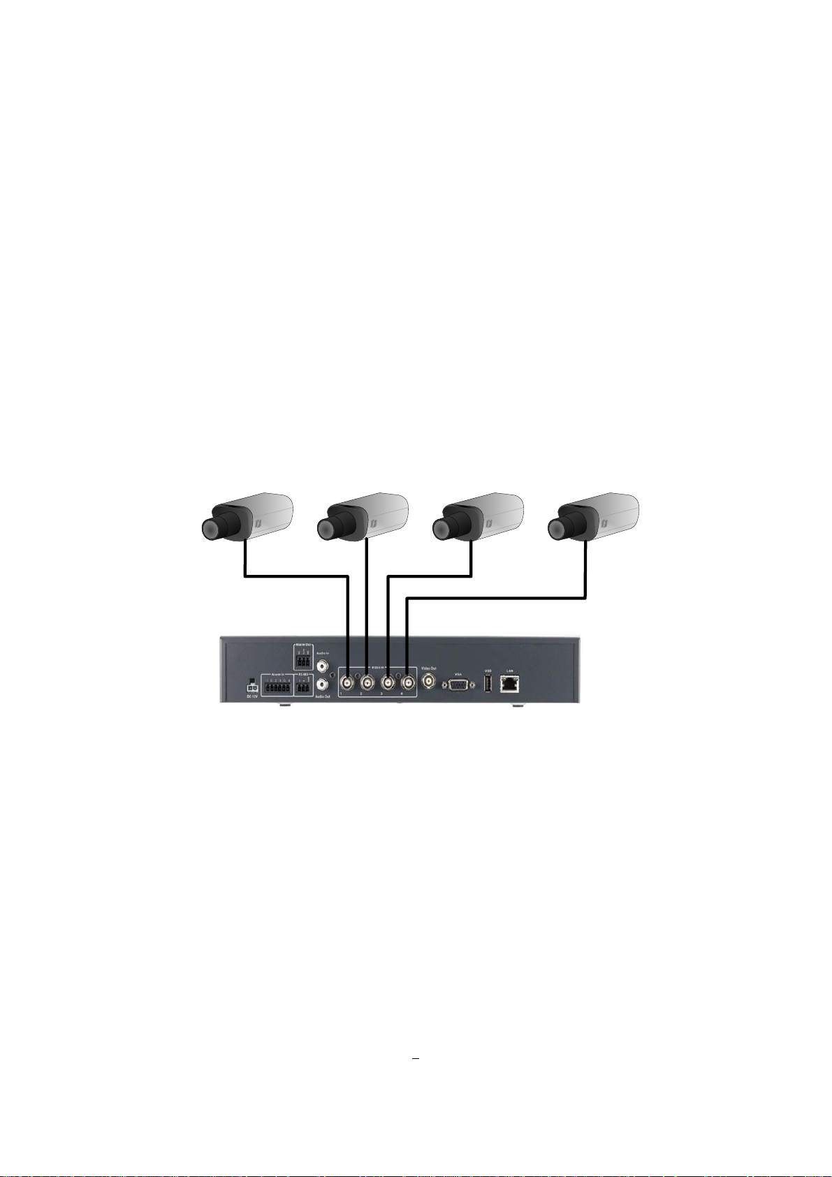
2.1 VIDEO INPUTS/OUTPUTS INSTALLATION
Camera and CCTV monitor must use 75 Ohm video cable (e.g. RG-59, RG-6, RG-11) with BNC
connectors .
Due to inappropriate absorbability, 50 Ohm coax cable (e.g. RG-58), antenna cable and other types of
coaxial cable are not comp atible.
All connected video sources must provide a 1 Vpp NTSC or PAL standard video signal.
When converting transmission lines (twisted pair, fibre optics, radio) to the video inputs, be sure to verify
accurate receiver calibration.
All 4 video inputs are terminated with 75 Ohm.
ATTENTION: In order for the system to auto-detect the appropriate video format (NTSC or PAL), make
sure that there is a video signal on video input 1 upon power-up.
5
Page 13
ERS-4 Instruction Manual
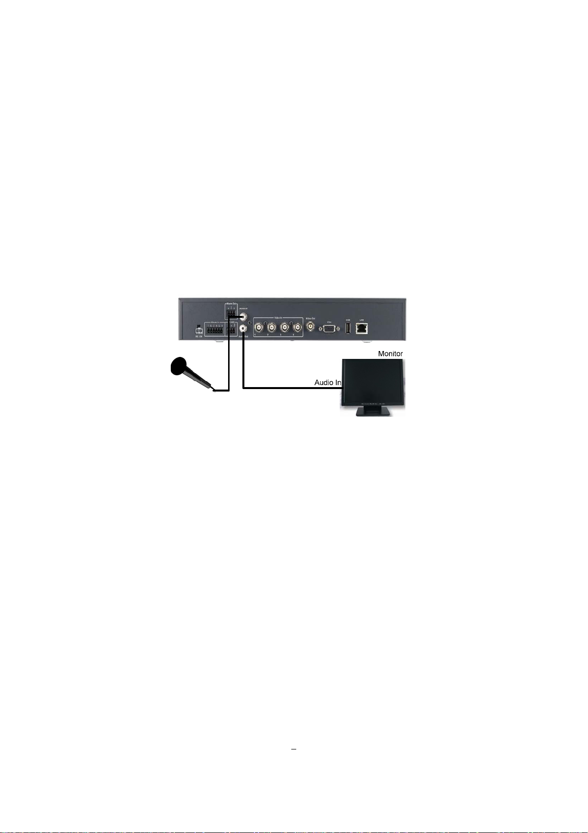
2.2 AUDIO INSTALLATION
The ERS-4 provides 1 audio input and 1 aud io output.
The input is designed for 500 mV (max. 1 V) to 10 KOhm line audio signals.
ATTENTION: The direct connection of a non-amplified microphone is not supported (a microphone
amplifier is required).
The installation must be done with audio coax cable and RCA plugs.
The output provides a typ. 500 mV /max. 1V to 10 KOhm line audio signal and may be connected to a
monitor‘s audio input or active speaker. The direct connection of passive speakers is not supported.
AUDIO RECORDING FUNCTIONALITY:
The audio channel is assigned to video channel 1.
Audio recording is activated / deactivated in the camera menu, camera 1.
Audio channel is always recorded together with camera 1 and is independent of the image recording rate.
6
Page 14
ERS-4 Instruction Manual
2.3 ALARM CONT ACTS INSTALLATION
The ERS-4 alarm inputs can be used for recording start or recording rate adjustment. Furthermore, alarm
reactions such as camera switching to monitors, buzzer, Email and network alarm are available.
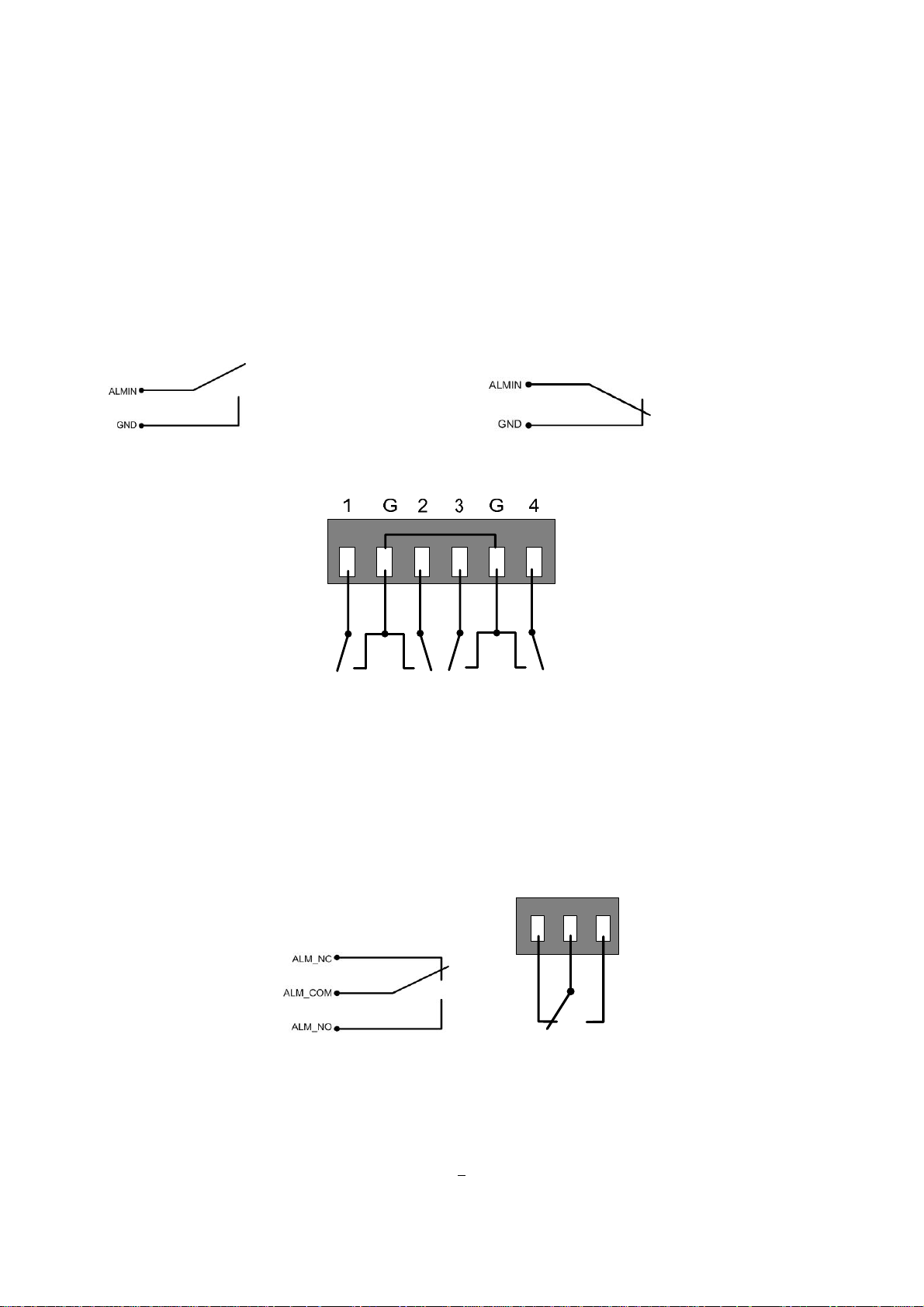
2.3.1 Alarm Input Contacts
ERS-4 provides 4 alarm inputs. All inputs are programmable N.O. (N ormal Open) or N.C. (Normal Closed)
Inputs have to be switched by dry contacts, default setting is N.O..
Alarm input with N.O. (Normal Open) contact Alarm input with N.C. (Normal Closed) contact
in idle state in idle state
Alarm inputs 1~4 of ERS-4
All settings are programmed in the ALARM menu.
2.3.2 Alarm Output Relay
The relay output provides either Normally Open or Normally Closed dry contacts.
NC
COM
NO
Output relay in idle state
7
Page 15
ERS-4 Instruction Manual
2.4 RS-485 KEYBOARD / PTZ INSTALLATION
The ERS-4 provides an RS-485 interface for PTZ control of speed domes and other PTZ devices.
Furthermore the ERS-4 can be remote-controlled by the EKB-500 universal keyboard. Keyboards and
speed domes can be installed on one single RS-485 bus. One system can comprise up to 8 keyboards.
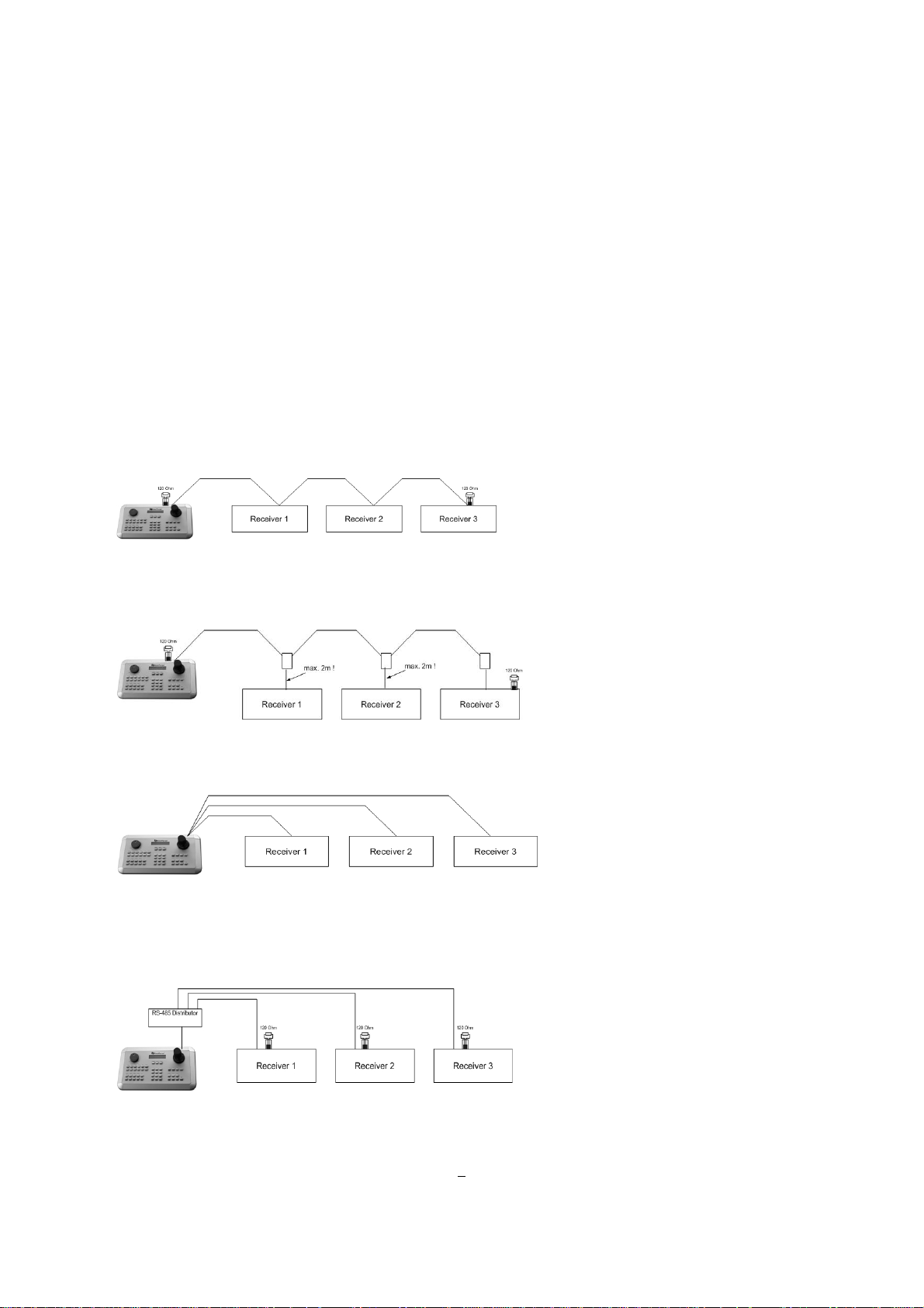
2.4.1 General RS-485 bus installation
The ERS-4 uses a RS-485 simplex wiring; the signal is transferred via a single twisted pair line. CAT5
network cable is recommended, UTP version (unshielded) is sufficient for nor mal application. A shielded
cable should be used if the installed cables are expected to be highly susceptible to interferences.
The number of devices installed in one bus is limited to 32, and the maximum cable length is 1200m. Bot h
of these can be expanded using a signal distributor (see below).
Both the first and the last device in series should be terminated with 120 Ohm resistance in order to
minimize l ine reflections.
RS-485 bus serial wiring
Cable length from box to device („Stubs“) has to be limited to 2m using connector boxes.
RS-485 bus serial wiring with connector boxes and connection cable
A direct RS-485 bus star wiring is not supported unless using a signal distributor (see below).
Improper RS-485 bus star wiring
A RS-485 signal distributor may be used to use a star wiring configuration.
Star wiring with RS-485 signal distributor
8
Page 16
ERS-4 Instruction Manual
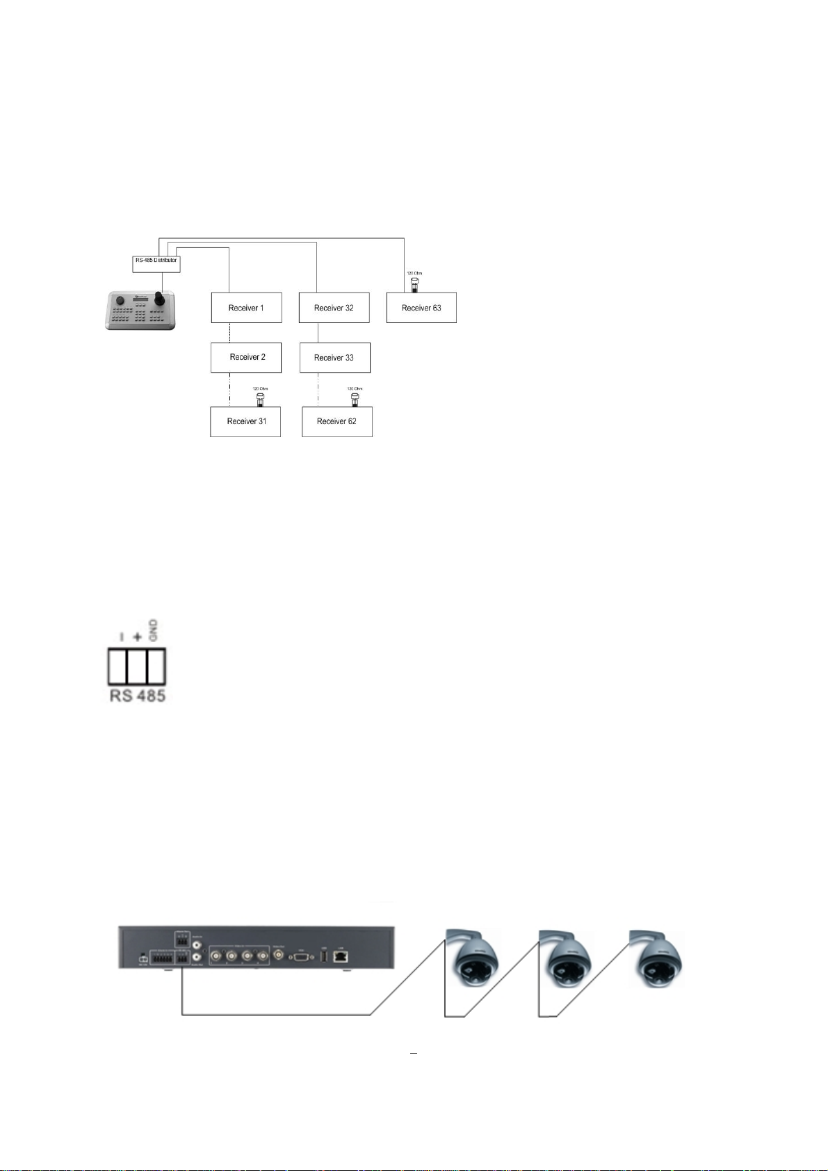
A RS-485 distributor can also be used to increase the maximum number of devices on the bus as well as
the total range. Each distributor output provides another RS-485 bus. This allows each output to extend an
additional 1200m, and it also enables the additional connection of 31 further devices to each output (the
output itself represents one device).
The maximum system expandability depends on the RS-485 address range of the installed devices.
System expansion with RS-485 signal distributor
ATTENTION: Most signal distributors are unidirectional! This means that the signal only flows from the
input towards the outputs. Therefore, e.g. the interconnection of several keyboards is not possible with
these types of signal distributor!
2.4.2 RS-485 terminal pin assignment
The following RS485 pin assignment as follow:
2.4.3 Speed Dome Installation
Speed dome or telemetry receiver pan/tilt/zoom control is available through web browser or the optional
PowerCon software if the ERS-4 is connected to a n e twork. Local tele metry control is provided by USB -
mouse control or by the optional EKB-500 keyboard.
Supported protocols: EverFocus, Pelco-D, Pelco-P, Samsung, Transparent
9
Page 17
ERS-4 Instruction Manual
Required ERS-4 settings: RS-485 receiver address in CAMERA menu
RS-485 parameters and protocol in the I/O CONTROL menu
ATTENTION: Some Pelco-D / -P protocol domes and receivers require an address offset of -1, i.e. the
address assigned to the dome / receiver in the ERS-4 camera menu must be 1 below the address set in the
dome / receiver itself!
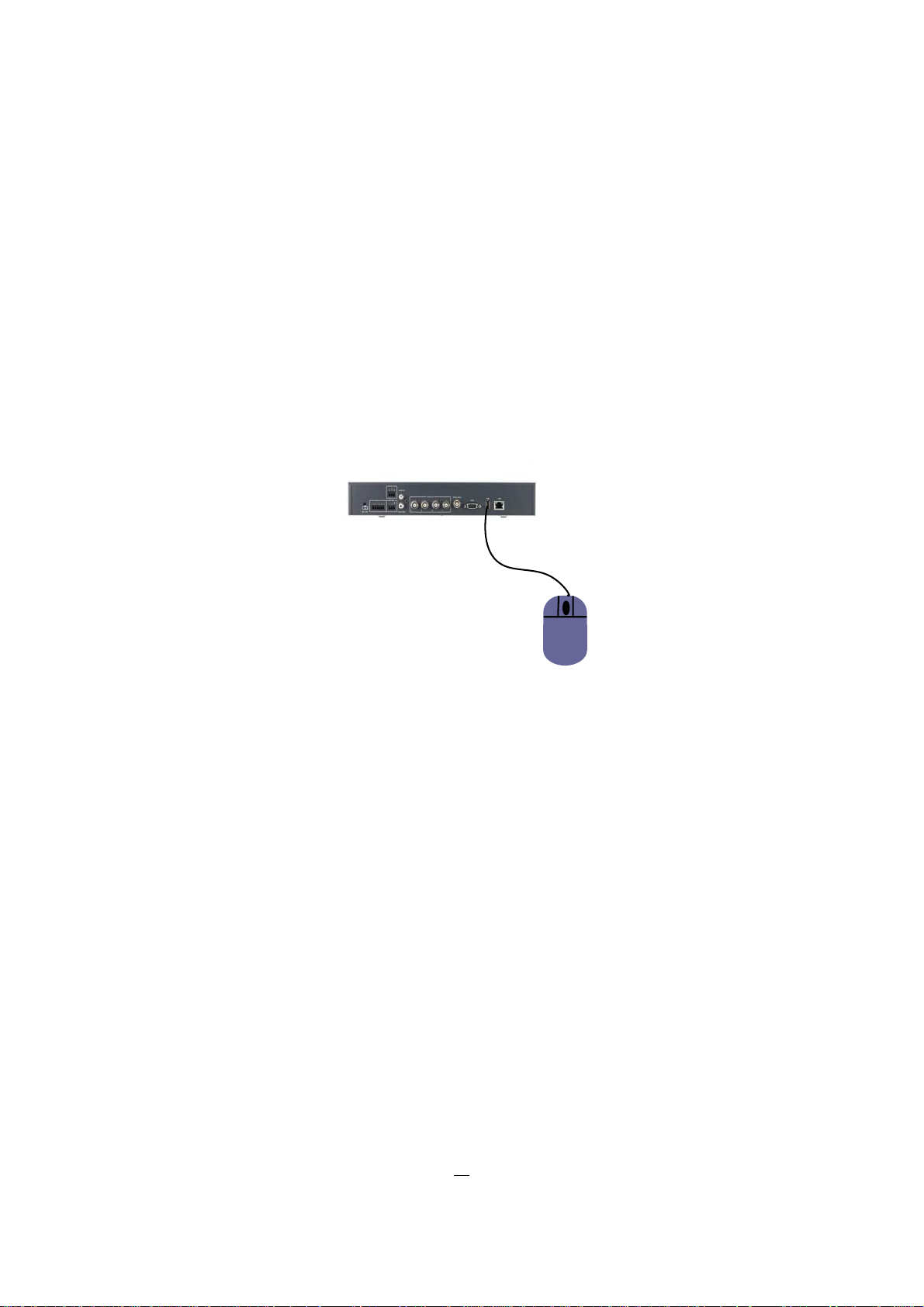
2.5 USB-MOUSE INSTALLA TIO N
For service and installation the ERS-4 can be operated by mouse at a local connected monitor.
All functions except playback and export are available at local operation.
Connect the USB mouse to the back panel USB port.
NOTE: Recommended mouse types are Logitech® and Microsoft® wired USB wheel-mouse. Wireless
USB mouse is no t supported.
10
Page 18
ERS-4 Instruction Manual
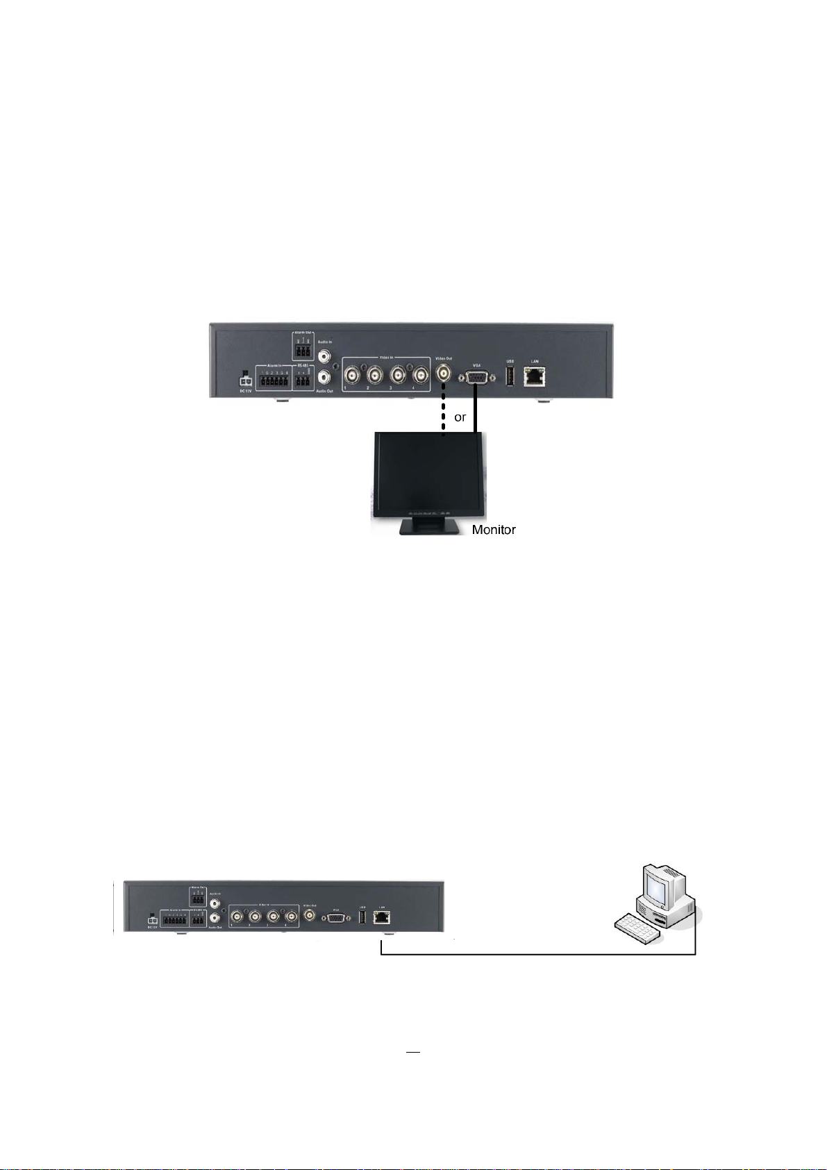
2.6 Monitor connection
For service and installation the ERS-4 can be operated by mouse at a local connected monitor.
All functions except playback and export are available at local operation.
The ERS-4 provides a composite Video output (BNC) and a VGA output (resolution 800x600 @ 60Hz) with
similar functionality. Depending on monitor type select one of these video outputs for monitor installation.
2.7 NETWORK CONNECTION
This section only describes physical connection to an Ethernet network. This step must be completed
before the ERS-4’s can connect to the network. Appendix C describes more Details for network
installations.
There are two basic types of connection:
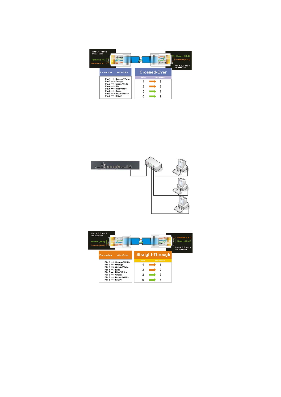
2.7.1 Direct PC Connection through Crossover Network Cable
The point-to-point connection of ERS-4 and PC requires a crossover (crossed) network cable. This type of
connection is ONLY used for direct connection to a single PC. Make sure that the PC is equipped with a
10/100/1000 Mbps compatible network connection.
Figure 2-1 Direct PC Connection
11
Page 19
ERS-4 Instruction Manual
Pin out of crossover-cable
2.7.2 Network Connection through Patch Cable
The connection to an existing network requires a normal patch cable (straight-through). The illustration
shows the connection to a network switch, router, or modem.
Figure 2-2 Network Connection through Patch Cable
Pin out of straight patch cable
2.8 Final Install Process
Once you have completed the basic wiring connections, you are ready to turn on the ERS-4. Plug in the
power source. The POWER LED will light up if power is normal. The system start-up will take ~ 1 minute
time.
12
Page 20
ERS-4 Instruction Manual
3 CONFIGURA TION VIA NETWORK
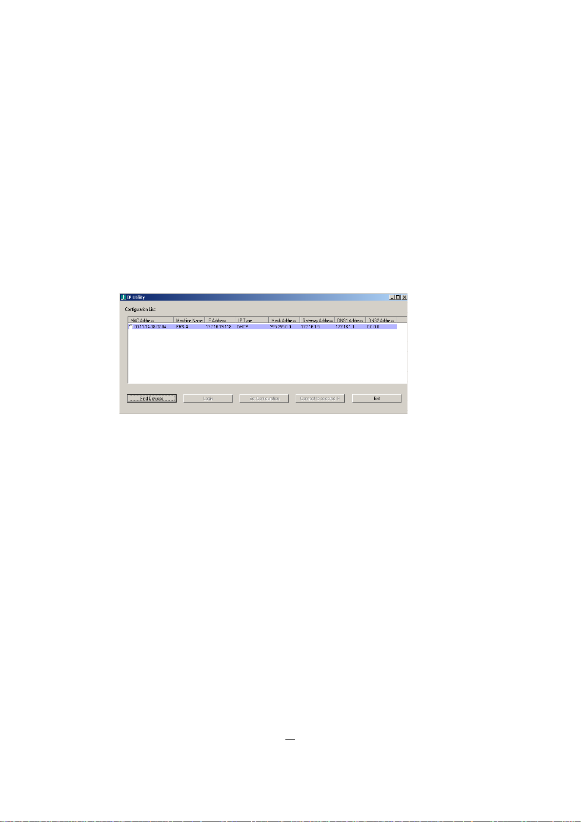
3.1 IP-SETUP VIA NETWORK WITH IP-UTILITY
The ERS-4 configuration can be done via network or locally at the device, if USB - mouse and monitor are
connected.
This chapter describes the remote network setup the ERS-4 Menu Settings step by step.
Start the application „IPUtility.exe“ from the application CD-ROM.
Click on „Find Devices“.
If connected to the network, the ERS-4 will be listed.
Select the ERS-4 and click on „Login“:
Enter user name and password.
Defaults: User name: user1
Password: 11111111
After successful login the „set configuration“ button is activated (not greyed).
Enter the new IP—parameters, then click on „Set Configuration“.
After ~ 30 seconds check by clicking on „Find Devices“, if the new settings were taken over.
13
Page 21

ERS-4 Instruction Manual
3.2 CONNECTING TO ERS-4
To access the ERS-4 from a computer, click on "Connect to selected IP" in the IPUtility tool window.
Alternative you can open Internet Explorer window and in the address bar type:
Local connection: http:// (IP address from the ERS-4’s Network Menu)
Internet connection: http:// (IP address given by your Internet Service Provider)
The login page will appear on the screen similar to the one shown above.
Enter a user name and password to access the recorder. These can be changed in the System section of
the Main Menu.
Default login data:
User name:
Password:
Click on the Login button and you will log in to the recorder’s Network Viewer.
user1
11111111
14
Page 22
ERS-4 Instruction Manual
3.3 BROWSER SECURITY SETTING
3.3.1 Installing ActiveX controls
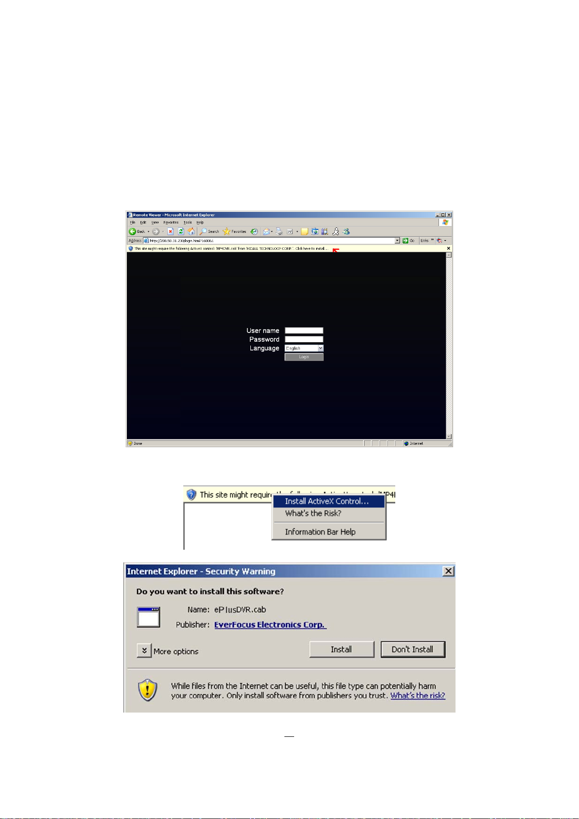
When you first connect to the ERS-4’s IP address, you should see a screen like the one below. If you do
not see a yellow bar like the one the arrow is pointing at, your security settings may be too high. If so, go to
next chapter: "Enabling ActiveX Controls.”
Right click on the yellow bar and select “Install ActiveX Control…”
15
Page 23

Install the ePlusDVR.cab file when prompted to do so.
Once the file finishes installing, you will return to the same login page as before.
Type in the username and password and click Login to view the cameras.
Default username:
user1
ERS-4 Instruction Manual
Default password:
11111111
16
Page 24
ERS-4 Instruction Manual
3.3.2 Enabling ActiveX Controls
Note: This section is only necessary if you DO NOT see the yellow ActiveX bar at the top
of your browser screen when you first connect to the ERS-4.
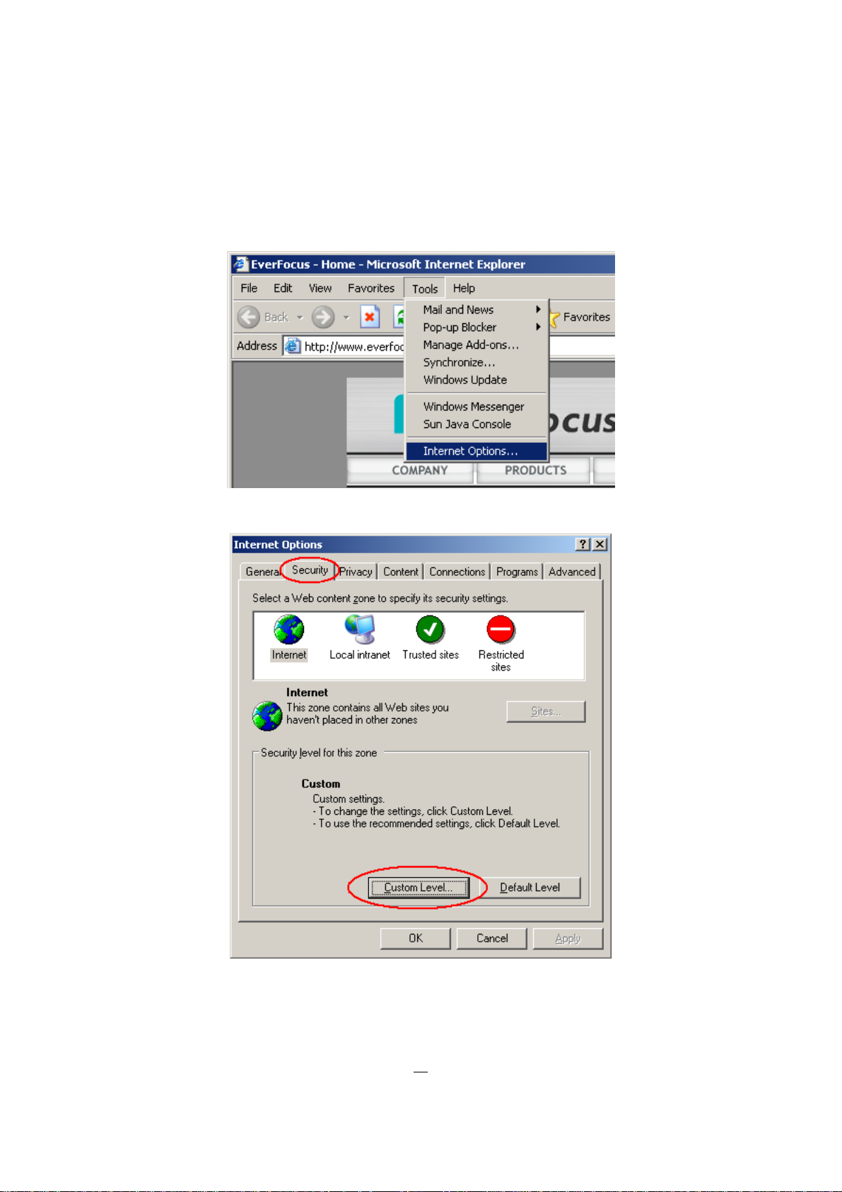
At the top of the Internet Explorer Window, click on Tools, then select Internet Options.
Click the Security tab at the top of the window, then choose Custom Level near the bottom.
17
Page 25
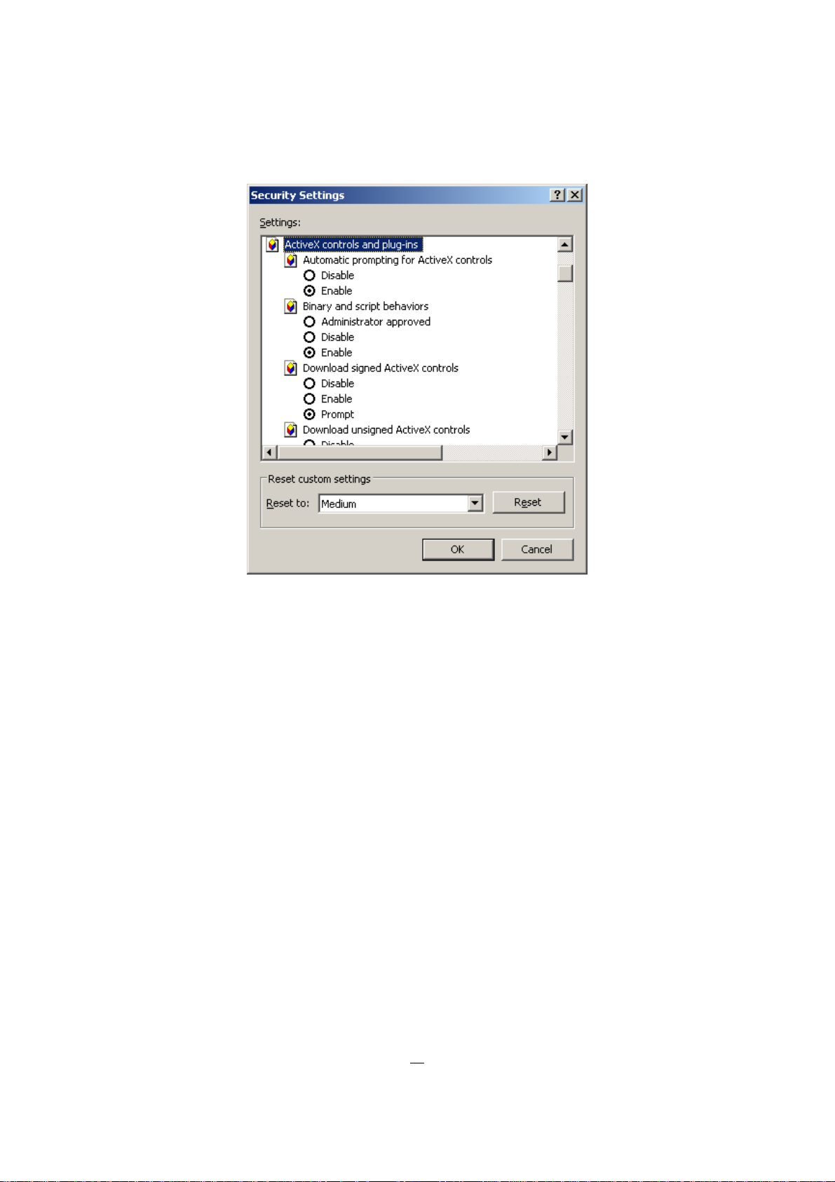
In the Security Settings window, scroll to “ActiveX controls and plug-ins”
ERS-4 Instruction Manual
Set the controls as follows:
“Enable”:
9 Allow previously unused ActiveX controls to run without prompt (Internet Explorer 7 only)
9 Allow scriptlets (IE7 only)
9 Automatic prompting for ActiveX controls
9 Binary and script behaviours
9 Display video and animation on a webpage that does not use external media player (IE7 only)
9 Run ActiveX controls and plug-ins
9 Script ActiveX controls marked safe for scripting
“Prompt”:
9 Download signed ActiveX controls
9 Download unsigned ActiveX controls
“Disable”:
9 Initialize and script ActiveX controls not marked as safe
Click OK and then choose Yes to change the security settings.
Close the window so you are back at the login screen.
Click the Refresh button to reload the page.
18
Page 26
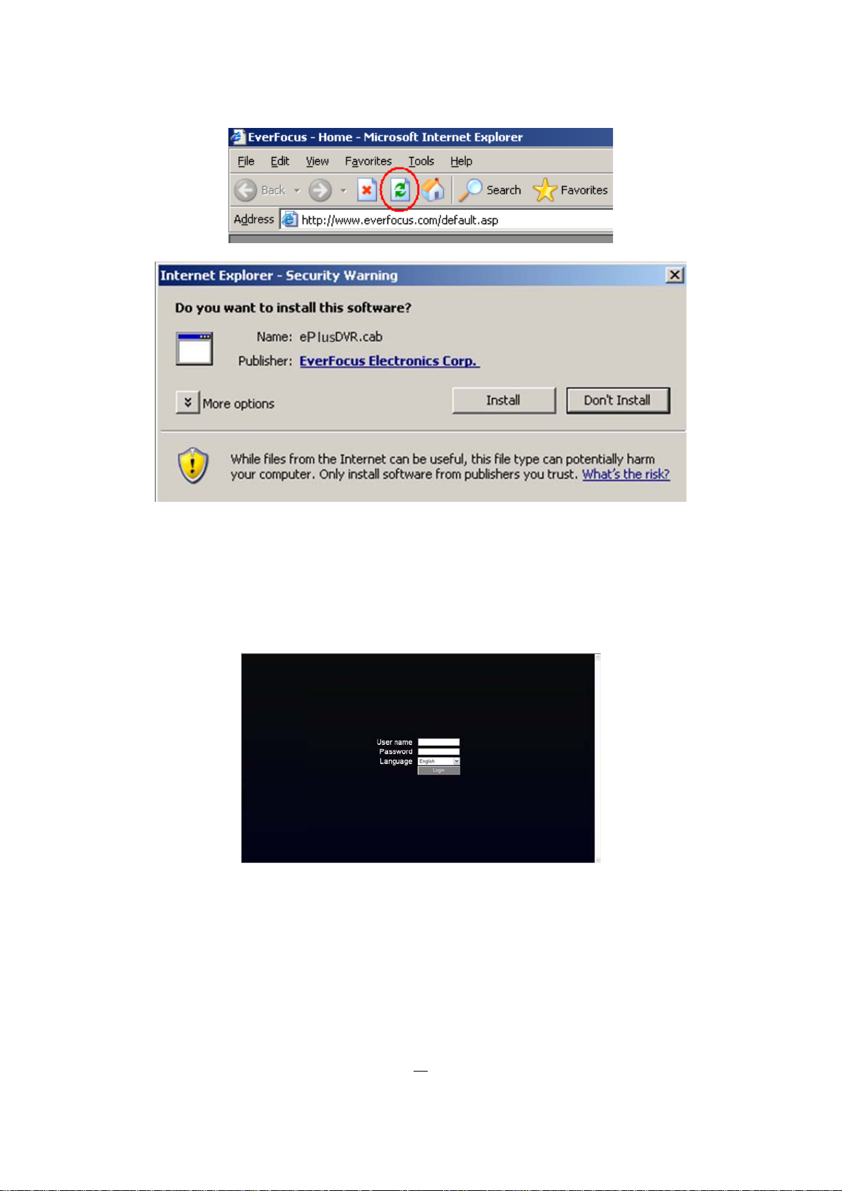
Install the ePlusDVR.cab file when prompted to do so.
Once the file finishes installing, you will return to the same login page as before.
Type in the user name and password and clic k Login to view the cameras.
Default user name:
user1
ERS-4 Instruction Manual
Default password:
After correct login the browser will show the ERS-4 live screen.
11111111
19
Page 27
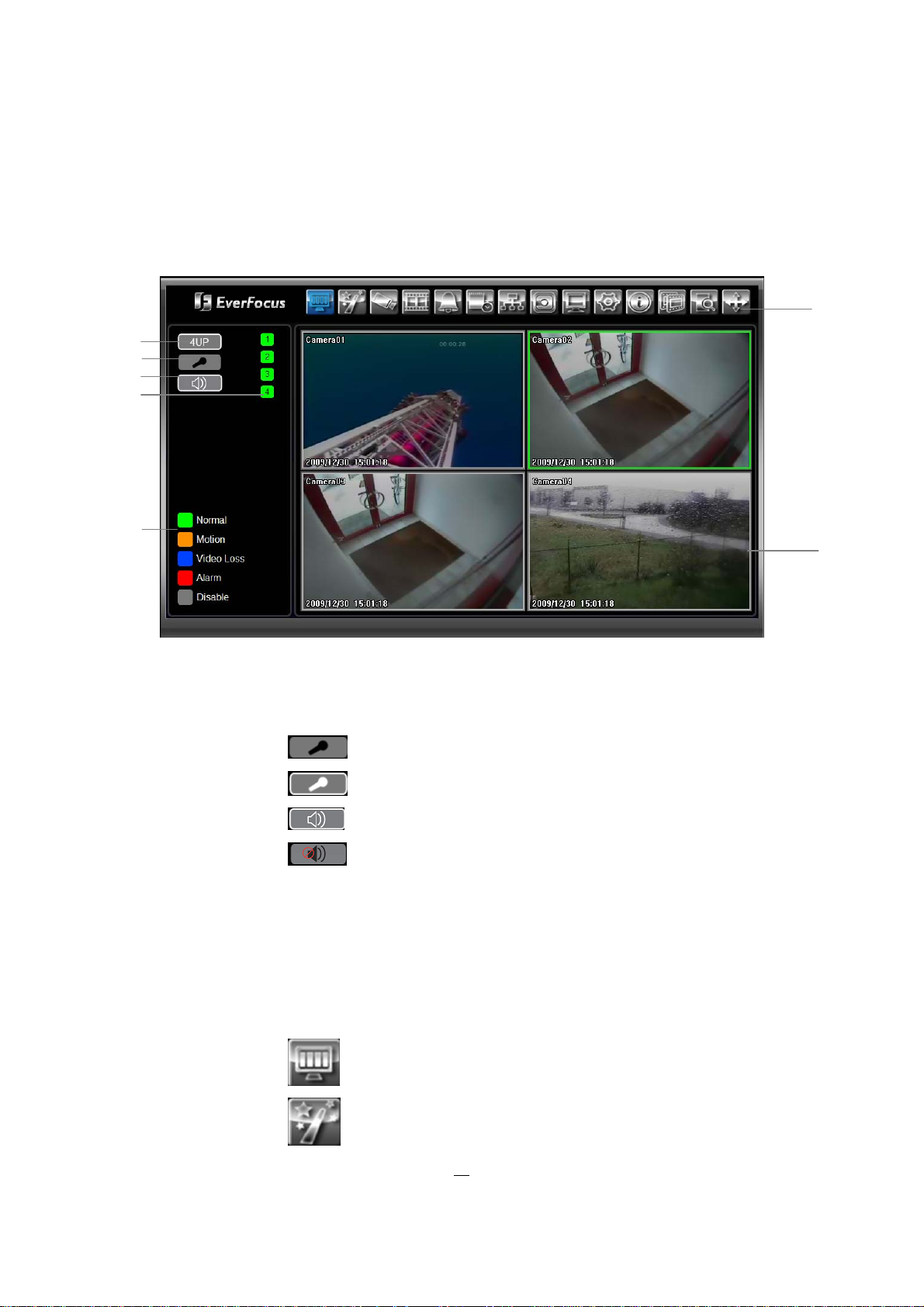
3.4 REMOTE LIVE SCREEN
After successful login the screen will show live view with all connected cameras.
ERS-4 Instruction Manual
1
2
3
4
5
1 4 x Screen Switches the video window to 4 x view of all cameras
2 Audio This button toggles audio transmission direction:
Listen mode (ERS-4 > PC)
6
7
Speak mode (PC > ERS-4)
3 Audio ON/OFF
Audio at PC enabled
Audio at PC disabled
4 Camera
channels
Clicking on the camera buttons switches to full screen mode of selected
camera.
The color of the button represents current status of the camera (#5)
5 Status Description of the status colors for camera buttons (#4)
6 Menu bar Menu buttons for setup, search and export, details are explained in following
chapters.
Live View
Express setup
20
Page 28

Camera setup
Record setup / recording time calculator
Alarm setup
Schedule setup
Network setup
Hard disk status / setup
System setup (date, time, user, interfaces, misc.)
ERS-4 Instruction Manual
Display setup (for local monitor output)
Info, system status informations
Video export
Playback search
PTZ control
7 Video window Area for live or playback view of the video channels
21
Page 29
ERS-4 Instruction Manual
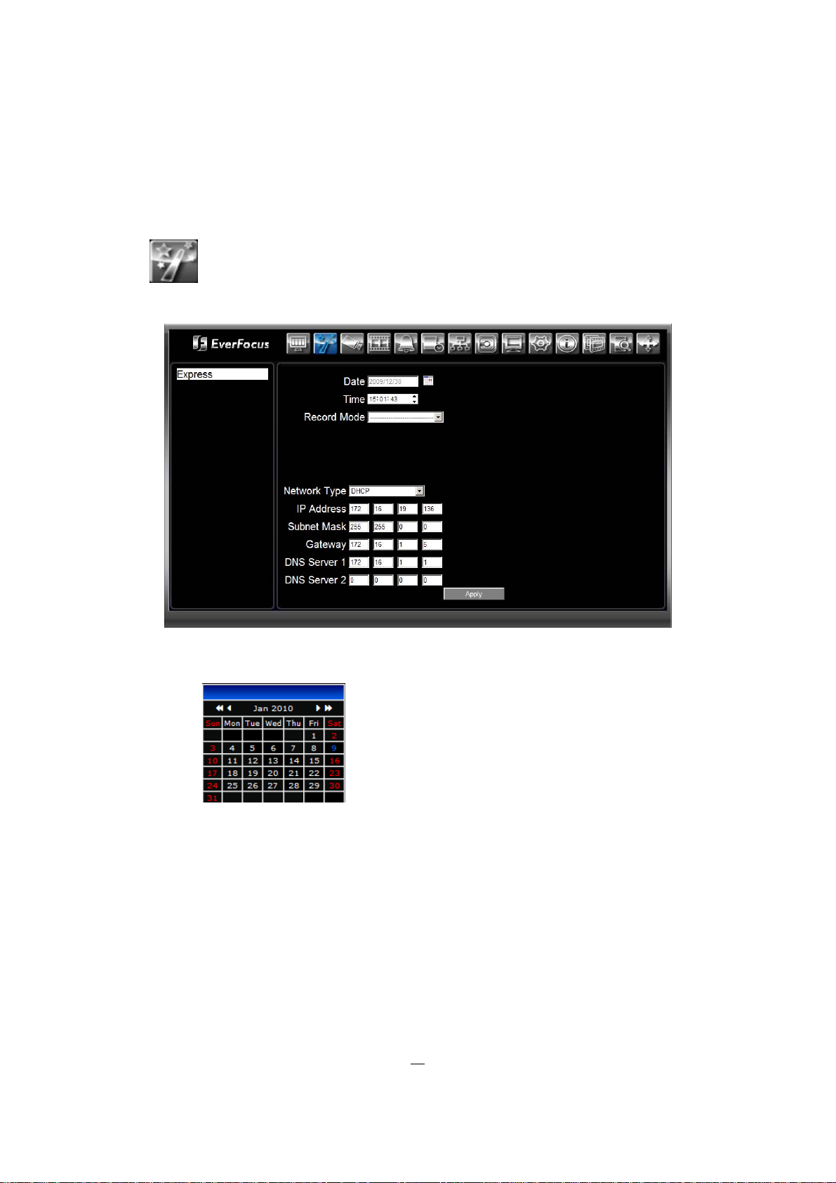
3.5 REMOTE SETUP - EXPRESS
The EXPRESS menu allows a fast configuration of all basic parameters without going through all other
menus. This allows configuring an ERS-4 for installations with simple requirements (no alarm, no enhanced
schedule setting, no advanced network settings...) within a few minutes at one menu page only.
Click on
to open the EXPRESS setup menu:
Date Click on the calendar icon.
Click on current date, ERS-4 will take over this date.
Time Select hour, minutes and seconds and adjust time with the up/down arrows.
Record mode 3 recording modes are available in EXPRESS menu:
Normal+Event: ERS-4 will record continuously with 1 IPS and with full frame
rate at motion event.
Enter the estimated total duration of motion (per day) in hours.
Event only: ERS-4 will only record, if motion appears.
Enter the estimated total duration of motion (per day) in hours.
22
Page 30

ERS-4 Instruction Manual
Scheduled Record: ERS-4 will work with following schedule setting:
Friday 18:00 to Monday 6:00:
only event record for all cameras 25/30 IPS
Monday to Friday 6:00 till 18:00:
continuous record 1 IPS and event record 25/30 IPS
Monday to Friday 0:00 till 6:00 and till 18:00 till 0:00:
only event record for all cameras 25/30 IPS
Resolution Select recording resolution based on video format.
PAL: 720x576 / 720x288 / 360x288
NTSC: 720x480 / 720x240 / 360x240
Record with The available selection in this menu item depends on selected record mode.
Modes "Event only " and "Normal+Event":
Preset settings:
Preset Setting Option Camera Item Apply value
Best Quality Quality Superior
Normal Frame Rate Max recording frame rate of ERS-4
Event Frame Rate 25 (PAL) / 30 (NTSC)
Standard Quality Quality Standard
Normal Frame Rate Half of max recording frame rate of ERS-4
Event Frame Rate 25 (PAL) / 30 (NTSC)
Extended Quality Quality Basic
Normal Frame Rate 1
Event Frame Rate 8 (PAL) / 10 (NTSC)
Recording days:
Case 1:
Record Mode: Normal + Event
Record With: Recording days
ERS-4 will Auto adjust Quality and Event frame rate to match the Recording days which
user selected:
According to resolution, event hours and assumption above, ERS-4 will select one set of
suitable quality and event frame rate from Changing Order 1 to 8. If ERS-4 can’t match
require record days from 8 sets of Change Order, it will just use the set of Changing Order
8.
Changing Order 1 2 3 4 5 6 7 8
Normal Frame Rate 1 1 1 1 1 1 1 1
Quality Superior Standard Low Low Low Low Low Low
Event Frame Rate
(PAL/NTSC) 25/30 25/30 25/30 12,5/15 8/10 6,25/7.5 5 1
Case 2:
Record Mode: Event Only
23
Page 31

ERS-4 Instruction Manual
Record With: Recording days
ERS-4 will Auto adjust Quality and Event frame rate to matc h the Recording days which
user need:
According to resolution, event hours and assumption above, ERS-4 will select one set of
suitable quality and event frame rate from Changing Order 1 to 8. If ERS-4 can’t match
require record days from 8 sets, it will just use the set of Changing Order 8.
Changing Order 1 2 3 4 5 6 7 8
Quality Superior Standard Low Low Low Low Low Low
Event Frame Rate 30 30 30 15 10 7.5 5 1
In "Schedule" mode is only the selection "Preset Settings" available (details above).
Network Type Static IP: Fixed IP-Address, IP parameters have to be entered below.
DHCP: If available, DHCP server in LAN will automatically assign IP for network
connection.
PPPoE: This is a DSL connection application only. Check with your ISP if they
use PPPoE.
IP-Address Enter the IP-address of the ERS-4 in your network.
If DHCP or PPPoE is selected, this value will be as signed automatically.
Subnet Mask Enter the Subnet mask of your network.
If DHCP or PPPoE is selected, this value will be as signed automatically.
Gateway Enter t he address of the Gateway in your network.
If DHCP or PPPoE is selected, this value will be as signed automatically.
DNS Server 1 Enter the address of secondary DNS Server in y our network.
If DHCP or PPPoE is selected, this value will be as signed automatically.
DNS Server 2 Enter the address of secondar y DNS Server in your network.
If DHCP or PPPoE is selected, this value will be as signed automatically.
Username Only in PPPoE mode: Enter user name of your account.
Password Only in PPPoE mode: Enter password of your account.
Apply Press “Apply” button to save and apply Express settings to ERS-4. The system will
automatically adjust recording frame rate according to settings. The following message
will pop up, press “Yes” to ch ange Resolution, Recording frame rate and Quality
depending on your express setting.
24
Page 32

3.6 REMOTE SETUP - CAMERA
3.6.1 Camera: Basic settings
This menu provides settings for general camera parameters.
ERS-4 Instruction Manual
Click on
to open the CAMERA setup menu:
Camera Select camera 1~4 for adjustment.
Title Enter a camera title (max. 16 characters).
Install Activate this checkbox for all installed cameras. Not installed camera channels
should be deactivated, otherwise system performance will be reserved for these not
used channels.
Covert If this checkbox is activated, cameras will not be visible (local and remote) and for
all users with "OPERATOR" user rights. Users with "ADMIN" and "MANAGER" user
rights still can see the camera.
Record Mode Select the recording mode:
Normal+Event: Continuous record (with Normal speed) and Event (Motion, contact
alarm) recording (with Event Speed)
Event Only: ERS-4 will record only events (motion, contact alarm).
Resolution Select recording resolution based on video format.
PAL: 720x576 / 720x288 / 360x288
NTSC: 720x480 / 720x240 / 360x240
Record Quality Select an image quality for recording. There are five different qualities available:
25
Page 33

ERS-4 Instruction Manual
Superior, High, Standard, Basic and Low.
A higher image quality uses more HDD space.
Normal Speed Frame rate in images per second (IPS) for continuous recording. The speed is
limited to the maximum recording rate of the ERS-4 (displayed on the right side of
this line) divided by the number of installed cameras. If the resolution option is
changed, the unit of this field will also be changed.
Recording capacity for all 4 cameras (shown next to the Normal Speed field): The
number here indicates the remaining recording capacity available for all 4 cameras.
When this number is positive, it means there is still recording capacity.
If this number is negative, it means the recording capacity has been exceeded, and
the user must lower Normal Speed or Resolution. This number must be positive
before saving the changes. Otherwise, a pop-up window will display “Fail" , enter
valid frame rates in this case and save again.
Event Speed Frame rate in images per second (IPS) for event (motion, contact alarm) recording.
Record Audio This checkbox appears only at page of camera 1 (Audio channel is assigned to
channel 1). Activate the checkbox for enabling audio record.
PTZ ID When using a PTZ Camera, activate PTZ control by switching to ON. The ID ( =
RS-485 addr ess) must match the ID used by the connected camera in order to
control the camera using the ERS-4.
Apply To This button can be used to copy the recording settings to other cameras. Select
which camera you wish to copy to. Camera titles and PTZ setting will not be copied.
"Select All" selects all cameras, “Unselect All” deselects all cameras. Click “OK” to
copy the settings or "Cancel" to exit without copying.
Save Ch 1...4 Clicking on this button will save the changed settings for this camera.
26
Page 34

3.6.2 Camera: Video Adjust
This menu allows optimizing the camera image.
ERS-4 Instruction Manual
Camera Select camera 1~4 for adjustment.
Brightness Brightness ad justment in the r ange 1~100.
Contrast Contrast adjustment in the range 1~100.
Color Color adjustment in the range 1~100.
Apply To This button can be used to copy the image settings to other cameras. Select which
camera you wish to copy to.
"Select All" selects all cameras, “Unselect All” deselects all cameras. Click “OK” to
copy the settings or "Cancel" to exit without copying.
Save Ch 1...4 Clicking on this button will save the changed settings for this camera.
27
Page 35

3.6.3 Camera: Motion
ERS-4 Instruction Manual
Camera Select camera 1~4 for adjustment.
Enable Check box to enable motion detection. Other motion options will not be available
unless this feature is selected.
Log Check box to record motion events in the log.
Main Monitor Reaction of (locally at ERS-4 installed) monitor:
No change: No change on the main monitor display.
Full screen: A full screen of the active camera will display on the main monitor.
Pre-alarm Record Check box to record several seconds before the motion event.
(Pre-alarm recording rate will follow “Normal” frame rate setting)
Buzzer Check box to enable buzzer when a motion event is triggered.
Email Notify Check box to send email notification when a motion event is detected.
Network Alarm Check box to send out a network alarm to client PC when motion occurs. (requires
PowerCon software and setting up Alarm Server in Network Setup menu)
28
Page 36

Edit Motion Grid Select the detection area in this submenu:
Sensitivity: Set the threshold value for sensitivity. Select from 1 (lowest) to 10
(highest).
Min Area: To avoid false detections by small objects this value defines, how
many grids have to be detected for generating a motion event.
Select a value between 1 (default) to 5 grids.
Set All: Press this button to select the entire area.
ERS-4 Instruction Manual
Clear All: Press this button to clear all the grids selected.
For defining a customized detection area click on "CLEAR ALL", the draw by mouse
(hold left mouse key) an area.
Close: Save setting and return to MOTION menu
Alarm Output In case of event the output relay will switch. It can be set to either “NONE” (not
active) or “1” (relay activated) .
Output Type Output action when motion is triggered.
Timeout Duration Alarm output lasts for the set time duration.
Transparent: Alarm is active as long the event is active.
Timeout: Automatic alarm reset after a defined time (Timeout
Duration)
Transparent+Timeout: Alarm will reset after event ended + Timeout Duration.
Apply To This button can be used to copy the image settings to other cameras. Select which
camera you wish to copy to.
"Select All" selects all cameras, “Unselect All” deselects all cameras. Click “OK” to
copy the settings or "Cancel" to exit without copying.
Save Ch 1...4 Clicking on this button will save the changed settings for this camera.
29
Page 37

3.6.4 Camera: Video Loss
This menu defines the reaction on video loss events.
ERS-4 Instruction Manual
Camera Select camera 1~4 for adjustment.
Enable Check box to enable video loss detection. Other motion options will not be available
unless this feature is selected.
Log Check box to record video loss events in the log.
Pre-alarm Record Check box to record several seconds before the video loss event.
(Pre-alarm recording rate will follow “Normal” frame rate setting)
Buzzer Check box to enable buzzer when a video loss event is triggered.
Email Notify Check box to send email notification when a video loss event is detected.
Network Alarm Check box to send out a network alarm to client PC when video loss occurs.
(requires PowerCon software and setting up Alarm Server in Network Setup menu)
Alarm Output In case of event the output relay will switch. It can be set to either “NONE” (not
active) or “1” (relay activated) .
Output Type Output action when motion is triggered.
Transparent: Alarm is active as long the event is active.
Timeout: Automatic alarm reset after a defined time (Timeout
Duration)
Transparent+Timeout: Alarm will reset after event ended + Timeout Duration.
Timeout Duration Alarm output lasts for the set time duration.
30
Page 38

ERS-4 Instruction Manual
Apply To This button can be used to copy the image settings to other cameras. Select which
camera you wish to copy to.
"Select All" selects all cameras, “Unselect All” deselects all cameras. Click “OK” to
copy the settings or "Cancel" to exit without copying.
Save Ch 1...4 Clicking on this button will save the changed settings for this camera.
31
Page 39

3.7 REMOTE SETUP: RECORD
The RECORD menu provides general recording settings and a recording time calculator.
ERS-4 Instruction Manual
Click on
to open the RECORD setup menu.
3.7.1 Record: Record
Record Overwrite With activated checkbox the ERS-4 will overwrite oldest records automatically, if
HDD is filled up.
Schedule Record With activated checkbox the ERS-4 will record with the settings from SCHEDULE
menu. In this case all recordi ng settings from CAMERA menu are overruled b y
SCHEDULE recording settings.
Time Stamp With activated checkbox the ERS-4 inserts a time / date overlay in the recording
stream.
Record Status
Output Relay
With selection "1" the output relay is activated during recording.
If this function is used, please make sure, that the relay is not used for other event
purpose.
Auto Erase Video OFF: The ERS-4 records with full HDD capacity, no recording time
limitation.
1~100 Days: Maximum recording duration. After the defined recording period
ERS-4 will delete oldest records and keep only records from defined
recording time period.
Apply Click on APPLY to save the changes.
32
Page 40

ERS-4 Instruction Manual
3.8 REMOTE SETUP: ALARM
The ALARM menu defines alarm and event reactions for input contacts and system events.
Click on
icon to open ALARM menu.
3.8.1 Alarm: Alarm
This menu defines behaviour of alarm input contacts.
Alarm Select input contact 1~4 for adjustment.
Enable Check box to enable input contact event. Other motion options will not be available
unless this feature is selected.
Log Check box to record input contact events in the log.
Pre-alarm Record Check box to record several seconds before the input contact event.
(Pre-alarm recording rate will follow “Normal” frame rate setting)
Buzzer Check box to enable buzzer when a input contact event is triggered.
Email Notify Check box to send email notification when a input contact event is detected.
Network Alarm Check box to send out a network alarm to client PC when input contact event
occurs. (requires PowerCon software and setting up Alarm Server in Network Setup
menu)
33
Page 41

ERS-4 Instruction Manual
Alarm Output In case of event the output relay will switch. It can be set to either “NONE” (not
active) or “1” (relay activated) .
Output Type Output action when input contact event is triggered.
Transparent: Alarm is active as long the event is active.
Timeout: Automatic alarm reset after a defined time (Timeout
Duration)
Transparent+Timeout: Alarm will reset after event ended + Timeout Duration.
Timeout Duration Duration of event for the Output types "TIMEOUT" and
"TRANSPARENT+TIMEOUT".
Enter the event duration in the range 1 ~ 150 seconds.
Main Monitor Reaction of monitor output on co ntact event:
No Change: Monitor keeps current display.
Full Screen: Monitor switches to full screen view of the camera, which is
selected under ACTIVE CAMERA
Input Type Contact type:
N.O.: Normal open, event is triggered if contact closes.
N.C.: Normal closed, event is triggered if contact opens.
Active Camera Selection of camera for full screen switching of monitor and PTZ preset position
reaction (if this function is activated).
Select camera 1~4.
PTZ Preset If the ACTIVE CAMERA is a camera with PTZ and preset - position function, it is
possible to move the camera in case of event to a desired preset position.
OFF: no camera movement
1~255: camera will move in case of event to selected preset position
Apply To This button can be used to copy the contact settings to other contacts. Select which
contact you wish to copy to.
"Select All" selects all contacts, “Unselect All” deselects all contacts. Click “OK” to
copy the settings or "Cancel" to exit without copying.
Save CH1...4 Clicking on this button will save the changed settings for this contact.
34
Page 42

ERS-4 Instruction Manual
3.8.2 Alarm: Event
This menu defines reactions on system events.
3.8.2.1 Event: Fan failure
This menu defines system reaction in case of cooler fan malfunction.
Note: This event is only needed for ERS-4 with build in Hard Disk. ERS-4 without Hard Disk are not
equipped with cooler fan.
Event Select FAN FAILURE
Log Check box to record fan failure events in the log.
Buzzer Check box to enable buzzer in case of cooler fan fault.
Email Notify Check box to send email notification in case of cooler fan fault.
Network Alarm Check box to send out a network alarm to client PC in case of cooler fan fault.
(requires PowerCon software and setting up Alarm Server in Network Setup menu)
Alarm Output In case of in case of cooler fan fault the output relay will switch. It can be set to
either “NONE” (not active) or “1” (relay activated) .
Output Type Output type is fixed to mode:
Transparent: Alarm is active as long the event is active.
Note: It is not possible to reset this alarm without solving the cooler fan problem.
Apply Save the settings for this event type.
35
Page 43

3.8.2.2 Event: HD Temperature
This menu defines the reaction on critical HDD temperature.
Event Select HD Temperature.
ERS-4 Instruction Manual
Log Check box to record HDD temperature events in the log.
Buzzer Check box to enable buzzer in case of HDD temperature events.
Email Notify Check box to send email notification case of HDD temperature events.
Network Alarm Check box to send out a network alarm to client PC case of HDD temperature
events. (requires PowerCon software and setting up Alarm Server in Network Setup
menu)
Stop Recording With activated checkbox the ERS-4 will stop recordin g for avoiding total damage of
HDD and data loss.
NOTE: It is not recommended to deactivate this check box !
Temp. Warning
Limit
Sets the trigger temperature for all other active settings in HD Temperature. Choose
from 55°C /131°F ~ 85°C /185°F.
Note: Do not set a higher value as the max. operating temperature of the installed
HDD (specified by HDD manufacturer) !
Alarm Output In case of event the output relay will switch. It can be set to either “NONE” (not
active) or “1” (relay activated) .
Output Type Output type is fixed to mode:
Transparent: Alarm is active as long the event is active.
Note: It is not possible to reset this alarm without solving the HDD temperature
problem.
Apply Save the settings for this event type.
36
Page 44

3.8.2.3 Event: HD failure
This menu defines the reaction on detected HDD errors.
Event Select HD Failure.
ERS-4 Instruction Manual
Log Check box to record HDD failure events in the log.
Buzzer Check box to enable buzzer in case of HDD failure events.
Email Notify Check box to send email notification case of HDD failure events.
Network Alarm Check box to send out a network alarm to client PC case of HDD failure events.
(requires PowerCon software and setting up Alarm Server in Network Setup menu)
Alarm Output In case of event the output relay will switch. It can be set to either “NONE” (not
active) or “1” (relay activated).
Output Type Output type is fixed to mode:
Transparent: Alarm is active as long the event is active.
Note: It is not possible to reset this alarm without solving the HDD problem.
Apply Save the settings for this event type.
37
Page 45

ERS-4 Instruction Manual
3.8.2.4 Event: HDD Full
This menu defines reactions, if full HDD capacity is reached.
Note: Settings in this menu are only active, if the ERS-4 works not in "OverWrite" mode (check box in
RECORD menu)
Event Select HD Full.
Log Check box to record HDD full events in the log.
Buzzer Check box to enable buzzer in case of HDD full events.
Email Notify Check box to send email notification case of HDD full events.
Network Alarm Check box to send out a network alarm to client PC case of HDD full events.
(requires PowerCon software and setting up Alarm Server in Network Setup menu)
Alarm Output In case of event the output relay will switch. It can be set to either “NONE” (not
active) or “1” (relay activated).
Output Type Output action when HDD full event is triggered.
Transparent: Alarm is active as long the event is active.
Timeout: Automatic alarm reset after a defined time (Timeout
Duration)
Transparent+Timeout: Alarm will reset after event ended + Timeout Duration.
Timeout Duration Duration of event for the Output types "TIMEOUT" and
"TRANSPARENT+TIMEOUT".
Enter the event duration in the range 1 ~ 150 seconds.
Apply Save the settings for this event type.
38
Page 46

3.8.2.5 Event: HD Off
This menu defines reaction, if HDD is disconnected.
ERS-4 Instruction Manual
Event Select HD off.
Buzzer Check box to enable buzzer in case of HDD off events.
Email Notify Check box to send email notification case of HDD off events.
Network Alarm Check box to send out a network alarm to client PC case of HDD off events.
(requires PowerCon software and setting up Alarm Server in Network Setup menu)
Alarm Output In case of event the output relay will switch. It can be set to either “NONE” (not
active) or “1” (relay activated).
Output Type Output action when HDD off event is triggered.
Transparent: Alarm is active as long the event is active.
Timeout: Automatic alarm reset after a defined time (Timeout
Duration)
Transparent+Timeout: Alarm will reset after event ended + Timeout Duration.
Timeout Duration Duration of event for the Output types "TIMEOUT" and
"TRANSPARENT+TIMEOUT".
Enter the event duration in the range 1 ~ 150 seconds.
Apply Save the settings for this event type.
39
Page 47

3.8.2.6 Event: Power Loss
This menu defines reactions in case of power loss.
ERS-4 Instruction Manual
Event Select Power Loss.
Log Check box to record Power Loss events in the log.
Email Notify Check box to send email notification case of Power Loss events.
Note: The notification will be send after power is switched on again.
Network Alarm Check box to send out a network alarm to client PC case of Power Loss events.
(requires PowerCon software and setting up Alarm Server in Network Setup menu)
Note: The notification will be send after power is switched on again.
Apply Save the settings for this event type.
40
Page 48

3.8.2.7 Event: Network Loss
This menu defines reactions in case of disconnected network.
ERS-4 Instruction Manual
Event Select Network Loss.
Log Check box to record Network Loss events in the log.
Buzzer Check box to enable buzzer in case of Network Loss events.
Alarm Output In case of event the output relay will switch. It can be set to either “NONE” (not
active) or “1” (relay activated).
Output Type Output action when Network Loss event is triggered.
Transparent: Alarm is active as long the event is active.
Timeout: Automatic alarm reset after a defined time (Timeout
Duration)
Transparent+Timeout: Alarm will reset after event ended + Timeout Duration.
Timeout Duration Duration of event for the Output types "TIMEOUT" and
"TRANSPARENT+TIMEOUT".
Enter the event duration in the range 1 ~ 150 seconds.
Apply Save the settings for this event type.
41
Page 49

ERS-4 Instruction Manual
3.9 REMOTE SETUP: SCHEDULE
The ERS-4-4 provides an enhanced schedule for recording periods. The Schedule includes an EXPRESS
Setup, Holiday list and separate alarm input timer.
Click on
for opening SCHEDULE menu.
Note: All schedule settings are active only, if the check box "SCHEDULE RECORD" in RECORD
menu is activated !
3.9.1 Schedule: Express Setup
The Express setup is an option for fast schedule setup, if the installation does not require individual settings
for each day and ea c h camera.
Express schedule creates a similar schedule for each camera with following time periods:
Weekend: Defaults: Start Friday 18:00, end Monday 06:00
Weekday daytime: Defaults: Start each weekday 6:00, end each weekday 18:00
Weekday nighttime: Defaults: Start each weekday 18:00, end each weekday 06:00
Holiday / Others: Settings for days, which are defined at "HOLIDAYS" menu page
All settings of the EXPRESS page can be modified at the SCHEDULE menu page.
Weekend Start Start time of the weekend period.
Weekend End End time of the weekend period.
Daytime Start Start time of daytime period for each weekday (all weekdays, which are not included
42
Page 50

ERS-4 Instruction Manual
in the weekend period).
Daytime End End time of daytime period for each weekday (all weekdays, which are not included
in the weekend period).
SCHEDULE
TABLE
Record Type Select one of the 3 modes for each time period:
Disabled: No records in this time period
Event only: ERS-4 recor ds only events
Normal+Event: ERS-4 works w ith continuous and event (contact and motion
events) record
Normal Recording frame rate for continuous record. Select a frame rate for each time
period.
Note: If recording resolution is set to 720x576 / 720 x480, maximum possible value
to frame rate i s 12,5 / 15 IPS . Entering 25 / 30 IPS exceed s max. Frame rate and
will create a "Fail" message. ERS-4 will not take over the value.
Event Recording fra me rate for event (contact and motion events) record. Select a frame
rate for each time period.
Event action With activated check box all event related actions such as buzzer, relay out, mail
and network notification are enabled for this time period.
Uncheck the check box to block this event actions for this time period.
Apply Click on APPLY will take over the EXPRESS settings in the schedule. You can
double-check and modify the settings at the SCHEDULE menu page.
Note: All schedule settings are active only, if the check box "SCHEDULE RECORD" in
RECORD menu is activated !
43
Page 51

ERS-4 Instruction Manual
3.9.2 Schedule: Holidays
The ERS-4 provides a Holiday list with up to 30 Holidays. Select HOLIDAY in SCHEDULE menu.
Date Type Select one of the 2 day types, HOLIDAY or OTHERS.
Recurrent Type Select one of the options for entering the date:
One time: Input of a single date, not repeated in following years
Month/Date: Input of month and date, this Holiday will be repeated in following
years
Month/Weekday: Input of month and day of the week, this Holiday will be repeated
in following years
Details Input of the date depending on the RECURRENT TYPE mode.
Prev / Next Browse page forwar d / backward ( 3 pages total ).
Apply Click on APPLY will take over the Holiday settings.
44
Page 52

ERS-4 Instruction Manual
3.9.3 Schedule: Schedule
This menu allows a detailed setup of schedule for each camera and day.
If schedule was defined already by EXPRESS SCHEDULE page , all the setting are displayed a nd editable
here.
Step 1: Select a camera and a day type (here: Holiday).
Step 2: For start time of a time frame double click o n the bar at desired time ( 3 0 min . steps
possible):
Repeated double-click changes the color of the bar for different recording modes,
colors are explained below the table:
Grey: no records
Orange: Event (contact and motion events) record only
45
Page 53

Blue: continuous and event (contact and motion events) record
Step 3: Repeat Step 2 for additional time periods:
Step 4: Edit recording setting for the defined day type:
ERS-4 Instruction Manual
Click on
for setup of record in g op t i o ns :
Set for each defined time period recording resolution, and event rate for normal and
event recording.
Event action: With activated check box all event r elated actions such as buzzer,
relay out, mail and network notification are enabled for this time period.
Uncheck the check box to block this event actions for this time period.
Click on CLOSE for saving settings and exit to SCHEDULE page.
Step 5: Repeat steps 1 ~ 4 for other day types and cameras, if individual settings are
required.
If similar settings can be used for other cameras and day types, go to step 6 / 7
Step 6: For copying the settings of selected day type to other day types click on
:
Select desired day types and click on OK.
46
Page 54

ERS-4 Instruction Manual
Step 7: For copying the settings of selected day type to other cameras click on
:
Select desired cameras and click on OK.
Step 8:
Click on
to finish and save the schedule settings.
Note: All schedule settings are active only, if the check box "SCHEDULE RECORD" in
RECORD menu is activated !
47
Page 55

ERS-4 Instruction Manual
3.9.4 Schedule: Alarm Action
This menu describes scheduled activation of alarm input contacts.
This schedule is independent from recording SCHEDULE menu and has higher priority for recording
settings.
Setup procedure is similar to the SCHEDULE setup page.
Step 1: Select a Contact and a day type (here: Holiday).
Step 2: For start time of a time frame double click o n the bar at desired time ( 3 0 min . steps
possible):
Repeated double-click toggles the color of the bar for enabled/disabled mode,
colors are explained below the table:
Grey: input contact disabled
48
Page 56

ERS-4 Instruction Manual
Orange: input contact enabled
Step 3: Repeat Step 2 for additional time periods:
Step 4: Repeat steps 1 ~ 3 for other day types and cameras, if individual settings are
required.
If similar settings can be used for other cameras and day types, go to step 5 / 6
Step 5: For copying the settings of selected day type to other day types click on
:
Select desired day types and click on OK.
Step 6: For copying the settings of selected day type to other contacts click on
:
Select desired cameras and click on OK.
Step 7:
Click on
to finish and save the schedule settings.
49
Page 57

3.10 REMOTE SETUP: NET WORK
This menu pages define all network related settings.
ERS-4 Instruction Manual
Click on
icon for opening network menu.
3.10.1 Network: LAN
Network Type Select the network Type:
Static IP: Fixed IP address
DHCP: If the connected network supports DHCP, the DHCP server will assign an
IP address to the ERS-4
PPPoE: For direct connection to DSL ONLY. Verify with your ISP if they use
PPPoE.
IP In STATIC IP mode enter the IP address of the ERS-4.
In DHCP and PPPoE modes the IP-address is assigned automatically, the address
is displayed only and not editable.
Subnet Mask In STATIC IP mode enter the subnet mask of connected network.
In DHCP and PPPoE modes the subnet mask is assigned automatically, the
address is displayed only and not editable.
Gateway In STATIC IP mode enter the gateway address of connected network.
In DHCP and PPPoE modes the gateway address is assigned automatically, the
address is displayed only and not editable.
50
Page 58

ERS-4 Instruction Manual
DNS-Server 1 In STATIC IP mode enter the address of DNS-Server 1 in connected network.
In DHCP and PPPoE modes the DNS server address is assigned automatically, the
address is displayed only and not editable.
DNS Server 2 In STATIC IP mode enter the address of DNS-Server 2 in con nected network.
In DHCP and PPPoE modes the DNS server address is assigned automatically, the
address is displayed only and not editable.
HTTP - Port HTTP port setting, default value is port 80.
Bandwidth limit In case of limited network bandwidth resources it is possible to limit maximum
streaming bandwidth of ERS-4:
Disable: No limitation (full streaming performance).
128k ~ 3M: Select max. network bandwidth.
Enable 3GPP
streaming
Activated check box allows access to live video streams of single video channels by
mobile phone. For details refer to APPENDIX B.
NOTE: The 3GPP streamin g is n ot pr otected by user na m e a nd pas s w ord.
This means, everybody, who knows IP-address and the syntax, can
access the ERS-4 by mobile phone or media player (which supports
RTSP such as VLAN player).
Please consider these security limitations before enab ling 3GPP
streaming!
PPPoE only:
User Name
This input field is active only in PPPoE mode:
Enter the user name of your DSL account.
PPPoE only:
Password
Apply
This input field is active only in PPPoE mode:
Enter the password of your DSL account.
Click on
to finish and save the settings.
51
Page 59

ERS-4 Instruction Manual
3.10.2 Network: Email
In case of events ERS-4 is able to send notifications by Email. This menu defines the Email account
settings.
SMTP Server Assign the SMTP (e-mail) server’s name.
Note: For more reliable emai l service, use the server’s IP address.
SMTP Port Assign the port number used by the SMTP server.
Authentification Activate the check box, if the SMTP server requires an authentication (user name /
password).
SSL Activate the check box, if the SMTP server supports SSL (Secure Sockets Layer)
transmission.
User Name If authentification is required, enter user name here.
Password If authentification is required, enter password here.
Sender Email Input sender’s e-mail address.
Note: Make sure to enter a valid Email address here. Otherwise most of the mail
server will block the Emails!
Receiver Email
Enter up to 3 Email addresses for receiving event notifications.
1..3
Email Subject Input email subject.
Apply
Click on
to finish and save the settings.
52
Page 60

3.10.3 Network: DDNS
The ERS-4 supports the free DNS services of DynDNS and EverFocus.
EverFocus DDNS allows creating an account directly from the ERS-4.
3.10.3.1 EverFocus DDNS
ERS-4 Instruction Manual
DDNS Service Select "EverFocusDDNS"
DVR Name For creating an account enter the desired name of the device.
Example:
Entering "cool-ers4" will create an account with following IP-address:
cool-ers4.everfocusddns.com
(if this IP-Address is not used for another account already).
The availability of EverFocusDDNS addresses can be checked also at the
webpage:
www.everfocusddns.com
Register / Update
After input of desired name click on
After the message "Success2 for sending the data the screen shows the status
message "Status updating"
.
53
Page 61

ERS-4 Instruction Manual
Wait until status message changes.
Option 1) Registration successful
The selected name was registered successful. If the ERS-4 is connected correctly
to the Internet, it can be accessed now under
http://[your registered name].everfocusddns.com
Option 2) Registration fail ed, no connection
This status message indicates, that no connection to DDNS server was established.
Check the network settings for gateway and DNS server, furthermore check port
forwarding settings in DSL router (if router is installed).
Option 3) Registration failed, selected name was registered already
Select a new name and try to register again.
Note: EverFocus DDNS addresses are not supported in PowerCon management software (Status version
4.3 and lower ) .
54
Page 62

3.10.3.2 Dyndns DDNS
Using an address of dyndns.org requires an existing account.
Create a free account at www.dyndns.org first.
ERS-4 Instruction Manual
DDNS Service Select "www.dyndns.org"
Host Name Name of the ERS-4, as defined at www.dyndns.org account settings
User Name User name of the dyndns.org account
Password Password of the dyndns.org account
Apply
Click on
to finish and save the settings.
55
Page 63

ERS-4 Instruction Manual
3.10.4 Network: Alarm Server
The ERS-4 can send network alarm notification to PowerCon software and other central management
systems, which support this function.
The notification can be transmitted to max. 3 receiving servers.
Server IP 1...3 Enter the IP - addresses of the receiving al arm servers
Protocol Type Select the protocol type:
UDP: User Datagram Protocol
TCP: Transmission Control Protocol
Note: Use UDP only for LAN applications, this mode is not safe for Internet
connections.
Port User name of the dyndns.org account
Network ID Enter the network ID (Unique ID) for network alarm.
Note: 1. The ID must contain 10 numbers.
2. Only numbers are valid characters
3. Do not use leading zeros.
Apply
Click on
to finish and save the settings.
56
Page 64

3.11 REMOTE SETUP: DISK
This menu gives information about Hard Disk status and allows formatting the HDD.
ERS-4 Instruction Manual
Click on
for opening Hard Disk menu.
Record Time (Start) Shows earliest recorded time on the hard drive.
Record Time (End) Shows latest or most current recorded time on the hard drive.
Format Formats (deletes) the HDD.
Click on
and confirm the screen message
with OK for formatting the HDD.
Note: All video and event data will be deleted in case of formatting.
Health Status Displays current status of the selected disk.
Disk Temperature Current HDD temperature.
Disk Size (Total) Shows total disk size.
Disk Size (Usage) Shows percentage of used disk space. If ERS-4 is set to auto matically ov erwrite
the disk, this option will show “Overwrite mode currently”.
57
Page 65

3.12 REMOTE SETUP: DISPLAY
The settings in this menu are related to the local Monitor output of ERS-4 only.
ERS-4 Instruction Manual
Click on
for opening MONITOR menu.
3.12.1 Monitor OSD
This menu provides settings for the Onscreen Display of local monitor.
Camera Title With activated check box the monitor dis plays camera titles (as defined in
CAMERA menu).
Date/Time With activated check box the monitor displays current date/time.
Event Status With activated check box the monitor displays event status.
HDD Status With activated check box the monitor displays hard drive status.
Text Insert Reserved for future applications.
BNC/VGA This system supports both VGA and BNC monitor displays at the same time but
only one of them can have optimized display quality. Use this feature
to select which output is optimized.
Apply
Click on
to finish and save the settings.
58
Page 66

3.12.2 Main M/T SEQ: Sequence
This menu defines the automatic switching sequence to the local monitor output.
Camera Select camera 1~4 for each step of the sequence.
Dwell Select a dwell time in the range 1~99 s econds to this camera.
Select "0" to skip this step in the sequence.
Apply
Click on
to finish and save the settings.
ERS-4 Instruction Manual
59
Page 67

ERS-4 Instruction Manual
3.13 REMOTE SETUP: SYSTEM
The SYSTEM menu provides setup options for time/date, user management, maintenance and others.
Click on
icon for opening SYSTEM menu.
3.13.1 System: Date / Time
The menu provides settings for manual time date adjustment and NTP time synchronisation.
Date Set current Date.
Time Set current Time.
Date Format Choose date format from yyyy/mm/dd, dd/mm/yyyy, and mm/dd/yyyy.
Time Format Select time format 12H or 24H.
Time Zone Select the time zone of current location.
NTP Enable / disable automatic time synchronisation by NTP server.
NTP Server Enter IP-Add ress of a valid NTP server.
To find a compatible NTP address, please follow these steps:
a) Go to a PC that is connected to the internet.
b) Click on “START” -> “RUN” -> type “command” and press “OK”.
c) In the DOS Prompt, type “ping pool.ntp.org” to find out the IP address of an
NTP Server.
NTP Update Interval Define the update interval for NTP time synchronisation (daily, weekly or monthly)
Apply
Click on
to finish and save the settings.
60
Page 68

3.13.2 System: Daylight Saving
This menu provides settings for automatic Daylight saving switching.
ERS-4 Instruction Manual
Daylight Saving Activated check box enables automatic Daylight Saving switching.
Start Date Start date of Daylight Saving period.
Start Time (hh:mm) Enter time when daylight saving period begins.
Set To (hh:mm) Enter the new time for begin of Daylight Saving period.
For most regions, this will be one hour ahead of the “Start Time”.
End Date End date of daylight saving time.
End Time (hh:mm) Enter the time when daylight saving time ends.
61
Page 69

ERS-4 Instruction Manual
3.13.3 System: User
The ERS-4 allows up to 10 user accounts with 3 different user right levels.
3.13.3.1 User right defi nition
User Rights Operator Manager Administrator
Network Operation
Live Views
PTZ
View covert cameras
Playback Search
Copy / Export
Info - Menu
View Log
Delete Log
Setup Menu
Edit own user nam e / pas s w o r d
Local Operation
Live Views
Display OSD ON/OFF
OSD Settings
Sequence
PTZ
View covert cameras
Info - Menu
View Log
Delete Log
Setup Menu
Edit own user nam e / pas s w o r d
9 9 9
○
○
○
○
9 9
9 9
9 9
9 9
9 9 9
○ ○
○ ○
○ ○
9
9
9
9 9 9
9 9 9
9 9 9
○
9 9
9 9 9
○
○
9 9
9 9
9 9 9
○ ○
○ ○
○ ○
9
9
9
9 9 9
62
Page 70

3.13.3.2 Edit user account
The default se t t i n gs pr ovide 3 users with dif f erent user right s :
User Name Password User Right Level
user1 11111111 Admin
user2 22222222 Manager
user3 33333333 Operator
ERS-4 Instruction Manual
For editing an account select the user and click on
User Name Edit the user name.
New Password Enter new password.
Confirm Re-enter the new pas sword for verification.
Level User Right Level
Status Enable: User account is active.
Disable: User account is disabled, but not deleted.
.
63
Page 71

3.13.3.3 Add user account
Click on
for creating new user account.
User Name Enter the user name.
New Password Enter the password.
Confirm Re-enter the password for verification.
ERS-4 Instruction Manual
Level User Right Level
Status Enable: User account is active.
Disable: User account is disabled, but not deleted.
3.13.3.4 Delete user account
Select a user acc ou nt and click on
for removing the user account from list.
After finishing all settings click on
for saving the changes.
64
Page 72

3.13.4 System: I/O Control
This menu defines parameters of the RS-485 interface.
ERS-4 Instruction Manual
PTZ Protocol PTZ protocol for connected PTZ camera, select protocol type EverFocus, Pelco-D,
Pelco-P, Samsung (Electron.) or Transparent.
In Transparent mode the protocol type is defined in the central management
software, this mode works only for network control.
485 ID Enter RS-485 ID (address) of the ERS-4 in the range 1 ~ 127, required for RS-
485 remote control by EKB500
Default: 1
Baud Rate Transmission speed of RS-485 interface, select 1200, 2400, 4800, 9600, 19200,
38400, 57600 or 115200 BPS
Default: 9600
Data Bit Data bit used for transmission, select 7 or 8
Default: 8
Stop Bit Stop bit used for transmission, select 1 or 2
Default: 1
Parity Parity setting for RS-485 transmission, select NONE, ODD or EVEN
Default: NONE
Apply
Click on
to finish and save the settings.
65
Page 73

3.13.5 System: Miscellaneous
This menu is needed for system maintenance and language settings.
ERS-4 Instruction Manual
Current Firmware
Displays the current version.
version
Firmware Upgrade Press “Upgrade” to upgrade the firmware.
Click on SEARCH and enter the correct update file "ers-4.bin" with new firmware.
Click on
will start the upgrade procedure. This may take several
minutes. ERS-4 will restart automatically after successful update.
NOTE: After updating it is mandatory to perform LOAD D E FAULT for avoiding
malfunctions!
Load Factory
Click on
will load the factory settings.
Default
Load From File
Save To File
Click on
Click on
will load the configuration from a configuration file.
will save current configuration to a config file.
Language Select menu- and OSD language for ERS-4
66
Page 74

4 NETWORK OPERA TION
4.1 LIVE SCREEN CONTROLS
ERS-4 Instruction Manual
6
7 8 9
10
11
1
2
3
4
5
12
1 4 x Screen
Switches the video window to 4 x view of all cam eras
2 Audio This button toggles audio transmission direction:
Listen mode (direction ERS-4 > PC)
Speak mode (direction PC > ERS-4)
3 Audio ON/OFF
Audio at PC enabled
Audio at PC disabled
4 Camera
channels
Clicking on the camera buttons switches to full screen mode of selected
camera.
The color of the button represents current status of the camera (#5)
5 Status Description of the status colors for camera buttons (#4)
6 Live View
Live View (current screenshot)
67
Page 75

7 Setup Icons The Setup menus are described in chapters 3.6 to 3.13.
Note: Access to setup menus is only possible for users with ADMIN user
rights.
8 Info
shows system status informations
9 Copy / Export
opens Video export menu
10 Playback Search
opens Playback search menu
11 PTZ
opens PTZ control (available only for PTZ cameras)
12 Video Window Area for live or playback view of the video channels
4.2 VIEW MODES
ERS-4 Instruction Manual
4.2.1 Full Screen
Click on one of the 4 camera buttons to view selected camera in full screen mode.
4.2.2 4 x Screen
Click on button to switch to video screen with all 4 cameras (quad view).
4.2.3 Frameless Video Screen
Double click in the video window switches to frameless video window (without operation control icons).
Double click in the frameless video window switches back to normal screen.
4.3 BIDIRECTIONAL AUDIO
This button toggles audio transmission direction:
Listen mode (direction ERS-4 > PC)
Speak mode (direction PC > ERS-4)
68
Page 76

ERS-4 Instruction Manual
4.4 PLAYBACK SEARCH
The ERS-4 provides 2 methods for playback search and evaluation, search by event and search by time /
date.
4.4.1 Event Search
This search method allows searching for motion and contact alarm records.
From: Date Enter the start date for playback search.
Time Enter the start time for playback search.
To: Date Enter the end date for playback search.
Time Enter the end time for playback search.
Camera Select the cameras for playback search.
Event Select one ore more even t types for pla yback search:
Alarm: Alarm contact inputs
Motion: Motion detection events
Video: Video Loss events
Search Click on
for starting playback search.
69
Page 77

ERS-4 Instruction Manual
After click on the screen show a list with the search results, depending on the number of
events the list may have several pages ( 4 pages in example below):
Select an item from the list and click on
the selected event video:
CONTROLS:
Fast backward 2x~32x
Playback backward
Stop
Pause
Play
Fast forward 2x~32x
Return to SEARCH results
button, the screen will show the playback window with
70
Page 78

ERS-4 Instruction Manual
In addition to the Copy / Export menu page it is also possible to export event video files directly from the
event search page.
Select one or more events (check box) and click on
button.
After entering file name and file path the screen shows a progress bar, until the export is finished:
71
Page 79

4.4.2 Time / Date Search
The search by time / date allows searching normal (continuous) or event records.
Play from:
ERS-4 Instruction Manual
Date Enter the start date for playback search.
Time Enter the start time for playback search.
Play
Click on
for starting playback search.
72
Page 80

ERS-4 Instruction Manual
4.5 VIDEO COPY / EXPORT
The COPY menu allows exporting video files to the client PC. Furthermore a file player software is
available for playback of video files on PC.
Camera Select one ore more cameras for video export.
Activate check box "SELECT ALL" for export of all cameras.
Start Date/Time Start date and time of export file.
End Date/Time End date and time of export file.
Copy now
Click on
, enter filename and file storage location and start the copy
procedure.
The progress bar shows the current status of transmission.
During transmission it is always possible to stop the export by clicking on
button.
Download Player
Click on
for downloading of the file player software.
This software is needed for playback of exported files in *.aver format from ERS-4.
73
Page 81

ERS-4 Instruction Manual
4.5.1 Export File Evaluation with EFPlayer Software
Use the downloaded software EFPlayer.exe to evaluate *.aver files exported from the ERS-4.
Start EFPlayer.exe at your PC.
Fullscreen
4 x view
9(8) x view
16 x view
JPG Snapshot
AVI conversion
Close Player
Stretch to fit screen
Playback status
Playback controls
Open video file
Channel selection
74
Page 82

ERS-4 Instruction Manual
4.6 PTZ CONTROL
If the connected camera is defined as a PTZ device (Speed Dome, PTZ head with RS-485 receiver), the
PTZ control panel is shown at left side after clicking on
button.
Required settings: 1. PTZ is enabled and RS-485 address is entered in CAMERA > BASIC SETTING.
2. RS-485 parameter are adjusted in SYSTEM > I/O CONTROL.
Pan - Tilt direction keys
Zoom in (+) , Zoom out (-)
Focus far (+), Focus near (-)
Iris open (+), Iris close (-)
Input field for preset, tour and pattern numbers
Number buttons
Clear numeric input
Start (for preset, tour, pattern
Save preset position
Delete preset position
Auto-Pan
Preset position
Preset Tour
Pattern
Input syntax:
Go to Preset Position PRESET > [number] > GO
Save Preset Position PRESET > [number] > SET
Delete Preset Position PRESET > [number] > DELETE
Start Preset Tour TOUR > [number] > GO
Start Pattern PATTERN > [number] > GO
Start Auto-Pan AUTO-PAN
Open Setup Menu PRESET > [95] > SET
Enter in Speed Dome OSD I+ ((iris open)
ESC / Cancel in Speed Dome OSD I- (Iris close)
NOTE: The availability of each PTZ feature depends on user camera type and used PTZ protocol !
75
Page 83

4.7 INFO
4.7.1 Info: System
The SYSTEM menu provides informations about hardware and firmware status of ERS-4.
ERS-4 Instruction Manual
Click on
icon for opening INFO menu.
Version Current Firmware version of ERS-4
Model Model Name
NTSC/PAL Video system of installation
Web Version Firmware version of ActiveX control (web browser)
IP IP - address of ERS-4
MAC MAC - Address of ERS-4
DVR Name Device name
Network ID Network ID for network alarm transmission
76
Page 84

ERS-4 Instruction Manual
4.7.2 Info: Log
Depending on settings the ERS-4 logs informations about events, system errors and user activities.
Select LOG in info menu:
Enter the desired start and end time for the log request.
Select the event type for the log search:
Configurations Confi guration changes
Event Recording and system events
Record Recording activiti e s
Operation Other operations
User Us er logins / logouts
Note: The event log data are stored on Hard Disk. ERS-4 without Hard Disk can only buffer a small
quantity of events in the buffer. The complete log is lost in case of power loss for ERS-4 without Hard
Disk.
77
Page 85

4.7.2.1 View Log
ERS-4 Instruction Manual
After entering the search parameters click on
button, the search results list is shown:
Depending on the number of events the list may be splitted on several pages. Browse between the pages.
Click on
button for returning to LOG menu.
4.7.2.2 Delete Log
Click on
button for deleting complete log.
4.7.2.3 Export LOG
The selected log entries can be exported to a file in *.txt format.
Click on
button for creating the log file.
78
Page 86

ERS-4 Instruction Manual
5 APPENDIX A: HDD ASSEMBLING
If the ERS-4 was delivered in the version without Hard Disk, it is possible to add a HDD with the optional
Hard Disk mounting kit ERS-HDMK.
The kit ERS-HDMK contains:
1 SATA connector cable
2 HDD power cable
3 Screws for HDD and brackets
4 Left side HDD bracket
5 Right side HDD bracket
6 Cooler fan
7 screws for cooler fan
1
2
3
4
5
6
7
79
Page 87

ERS-4 Instruction Manual
5.1 OPEN ERS-4 HOUSING
Unscrew the 2 screws at each side of ERS-4 for removing the cover.
Lift the back side of the cover first, take care for the middle mount at front side (marked red).
80
Page 88

5.2 MOUNTING HDD BRACKETS
Assemble the HDD-brackets with 2 screws each at both sides of HDD.
Connector side
ERS-4 Instruction Manual
81
Page 89

5.3 ASSEMBLING COOLER F AN
Mount the cooler fan with the 2 fan screws at the right housing side.
Please make sure for correct cable position and airflow direction (intake fan):
ERS-4 Instruction Manual
Connect the plug of fan cable to the fan connector at the main board:
82
Page 90

5.4 SA TA AND POWER CABLE INSTALLATION
Connect the power cable and SATA cable to the main board:
ERS-4 Instruction Manual
Connect SATA and power cable to the pre-assembled HDD before mounting the HDD to the housing.
Make sure f or correct po sition of power cable.
83
Page 91

5.5 HDD MOUNTING IN HOUSING
Mount the pre-assembled HDD in the ERS-4 housing with 2 screws for each bracket:
ERS-4 Instruction Manual
Left brack et position Right bracket position
84
Page 92

5.6 CLOSING ERS-4 HOUSING
Lift back part for inserting cover in front panel:
ERS-4 Instruction Manual
Please make sure, that part 1 is inside front panel and part 2 outside the base plate:
Fix the cover with the 2 screws at each side.
85
Page 93

ERS-4 Instruction Manual
6 APPENDIX B: 3GPP MOBILE PHONE
STREAMING
6.1 GENERAL REQUIREMENTS
Mobile phone access to the live streams of the ERS-4 requires a media player on the mobile phone, which
allows RTSP streaming.
Furthermore 3GPP streaming has to be enabled in ERS-4 network menu.
The stream address has the syntax:
Live stream Channel 1:
Live stream Channel 2: rtsp:// [IP-Address of ERS-4]/live1.3gp
Live stream Channel 3: rtsp:// [IP-Address of ERS-4]/live2.3gp
Live stream Channel 4: rtsp:// [IP-Address of ERS-4]/live3.3gp
NOTE: The 3GPP streaming is not protected by user name and password. This means,
everybody, who knows IP-address and the syntax, can access the ERS-4 by mobile
phone or media player (which supports RTSP such as VLAN player).
Please consider these security limitations before enabling 3GPP stre a m ing!
rtsp:// [IP-Address of ERS-4]/live0.3gp
6.2 APPLE IPHONE
Viewing ERS-4 Live-Streams on iPhone requires installation of a media player, which supports RTSP
streaming.
One possible application is STREAMER. download STREAMER from APPLE
1. Start / enable STREAMER.
2. Select Bookmarks function.
3. Add Bookmarks with follo wing syntax:
Live stream Channel 1: rtsp:// [IP-Address of ERS-4]/live0.3gp
Live stream Channel 2: rtsp:// [IP-Address of ERS-4]/live1.3gp
Live stream Channel 3: rtsp:// [IP-Address of ERS-4]/live2.3gp
Live stream Channel 4: rtsp:// [IP-Address of ERS-4]/live3.3gp
Save settings
4. Select one of the saved bookmarks for live stream of ch. 1 ~4.
86
®
store and install.
Page 94

ERS-4 Instruction Manual
6.3 OTHER MOBILE PHONES
Mobile phone access to the live streams of the ERS-4 requires a media player on the mobile phone, which
allows RTSP streaming.
Following mobile phone types were tested successful for 3GPP streaming (with RealPlayer application):
NOKIA N93i
NOKIA N95
NOKIA N96
NOKIA N97
NOKIA N97 mini
NOKIA 5530 XpressMusic
NOKIA 5800 XpressMusic
HTC Hero
Apple iPhone 3G S 16GB (with STREAMER player)
87
Page 95

ERS-4 Instruction Manual
7 APPENDIX C: NETWORKING
7.1 NETWORKING OVER VIEW
This chapter will give you a basic instruction on how to set up the ERS-4 for network connection. It is highly
recommended that you have a working knowledge of what a network is and how it works. This will be
helpful in completing the networking process.
7.1.1 Introduction to TCP/IP
TCP/IP is the group of protocols used by the Internet and most Local Area Networks (LANs) throughout the
world. In TCP/IP, every computer or other communications device that is connected to the network ha s a
unique IP address. By doing this you are giving your device a unique address similar to the address of your
house. An IP address is composed of four octets (numbers in the range of 0 to 255) separated by decimal
points. The IP address is used to uniquely identify a host or computer on the LAN. For example, one
computer on a network could have an IP address of 192.168.1.127.
You should never give two or more devices the same exact IP address, but the first three octets of an IP
address should be the same for all computers in the local area network. For example, if a total of 253
computers exist in a single LAN, the IP addresses could be assigned starting with 192.168.1.x, where x
represents a number in the range of 2 to 254.
7.1.2 Subnet Masks
Each host in a LAN has a subnet mask. The subnet mask is a set of octets that is used to determine which
LAN or class it belongs to. The number 255 is usually used to represent the network address portion of the
IP address and a zero is placed at the end to identify the host portion of the address. Basically the subnet
mask can be compared to the city you live in for your home address, but in this case you are stating the
network you belong too.
7.1.3 Gateway Address
Each host in a LAN has a gateway. A gateway address is composed of four octets separated by decimal
points. The gateway address is used to uniquely identify the main host or computer on the LAN that
assigns the IP addresses to your network (usually a router). This is comparable to the zip code of your
address.
7.1.4 Virtual Ports
A port number represents a "channel" or entryway for network communications. Port numbers allow
different applications on the same computer to utilize network resources without interfering with each other.
Port numbers most commonly appear in network programming, particularly socket programming.
Sometimes, though, port numbers are made visible to the casual user. For example, some websites on the
Internet use a URL like the following:
http://www.fakeaddress.com:8100/
88
Page 96

ERS-4 Instruction Manual
In this example, the number 8100 refers to the port number used by the browser to connect to the web
server. The standard port number used by web sites is 80, so this number does not need to be included
with the URL (although it can be). In IP networking, port numbers can theoretically range from 0 to 65535.
Most popular network applications, though, use port numbers at the lower end of the range (such as 80 for
HTTP). Ports are similar to doors and windows of your house, with port 80 acting as the front door. If these
are not open you could not enter the house. This is the same case with ports on a network. If the ports for a
specific IP address are not open then you could not gain access to that IP address.
Note: The term port also refers to several other aspects of network technology. A port can refer to
Ethernet connection points, such as those on a hub, switch, or router. The term port is also used to
refer to a physical connection point for peripheral devices such as serial, parallel, and USB ports.
89
Page 97

ERS-4 Instruction Manual
7.2 WHAT IS YOUR NETWORK SETUP?
Everfocus DVR’s and IP - products can operate using one of three types of networking connections.
1. Simple One to One Connection: A simple one to one connection is the simplest type of network
connection. It uses a cross-over cable to make a direct connection from one computer to another
(or in this case a computer to a DVR).
2. Direct High Speed Modem Connection: A direct modem connection uses a standard network cable
to connect the modem directly to a computer (or in this case a modem to the DVR). This type of
connection only covers single-port modems. For a combination modem/router, use the setup
described below.
3. Router or LAN Connection – A local area network connection requires either a router or a preexisting LAN connection. This is the most common type of connection. A router allows multiple
computers and DVR’s to access each other as well as the Internet. It assigns different internal IP
addresses to the computers.
7.2.1 Simple One to One Connection
Crossover Ethernet Cable Pin outs:
The Figure below shows the pin configurations for a cross-over cable.
90
Page 98

ERS-4 Instruction Manual
Connection Procedure:
¾ The First step is to purchase or make a cross-over cable. We recommend purchasing one if you
have never made a cross-over cable. Please remember you can not use a straight through network
cable for this application
¾ Once you have a cross-over cable plug one end into the LAN port on the back of the DVR and the
other into the network card on the back of the computer.
¾ Log into the EverFocus DVR menu and go to the Network Setting Menu.
¾ You must use the Static IP option for this type of connection.
¾ Assign an IP of 192.168.001.003, a Subnet Mask of 255.255.255.000, and a Gateway of
192.168.001.001. You can ignore DNS Server.
¾ The next step is to set the computer’s network settings to match those of the DVR. You will need
Administrator privileges on your Windows machine to do this.
¾ To assign a fixed IP address in Windows 2000/XP.
91
Page 99

ERS-4 Instruction Manual
92
Page 100

ERS-4 Instruction Manual
93
 Loading...