

Page 1
2 Megapixel Full HD-CCTV
Camera
Operation Instructions
Model No.
Please read this manual first for correct installation and operation. This manual should be retained for future
reference. The information in this manual was current when published. The manufacturer reserves the right
to revise and improve its products. All specifications are therefore subject to change without notice.
PRECAUTIONS
1. Do not install the camera near electric or magnetic fields.
Install the camera away from TV/radio transmitters, magnets, electric motors, transformers and audio
speakers since the electromagnetic fields generated from these devices may distort the video image.
2. Never disassemble the camera beyond the recommendations in this manual nor introduce
materials other than those recommended herein.
Improper disassembly or introduction of corrosive materials may result in equipment failure or other
damage.
3. Try and avoid facing the camera toward the sun.
In some circumstances, direct sunlight may cause permanent damage to the sensor and/or internal
circuits.
4. Keep the power cord away from water and other liquids and never touch the power cord with
wet hands.
Touching a wet power cord with hands or touching the power cord with wet hands may result in electric
shock.
5. Never install the camera in areas exposed to water, oil or gas.
Water, oil or gas may result in equipment failure, electric shock or, in extreme cases, fire.
6. Cleaning
Do not touch the surface of the sensor directly with the hands. Use a damp soft cloth to remove any
dirt from the camera body. Use lens tissue or a cotton tipped applicator and ethanol to clean the sensor
and the camera lens. Please do not use complex solvents, corrosive or abrasive agents for cleaning.
7. Do not operate the camera beyond the specified temperature, humidity or power source ratings.
Use the camera at temperatures within 0℃ ~ 45℃ (32℉~113℉) and humidity between 20~80%.
The input power source is 12VDC/24VAC.
EQH5200
Page 2

TABLE OF CONTENTS
1. PRODUCT OVERVIEW...............................................................................................................2
1.1 Main Features............................................................................................................................................... 2
1.2 Package Contents.......................................................................................................................................... 2
1.3 Specifications................................................................................................................................................ 3
1.4 Dimensions................................................................................................................................................... 3
2. NAMES AND FUNCTIONS OF PARTS.........................................................................................4
2.1 Front panel.................................................................................................................................................... 4
2.2 Top/Bottom Mounting ..................................................................................................................................... 4
2.3 Back panel and connections........................................................................................................................... 5
3. INSTALLATION...........................................................................................................................6
4. OSD Menu & Configuration..........................................................................................................7
4.1 Exposure ....................................................................................................................................................10
4.1.1 Lens ........................................................................................................................................................10
4.1.2 Shutter..................................................................................................................................................... 10
4.1.3 Iris........................................................................................................................................................... 10
4.1.4 AGC (Auto Gain Control – basic low light signal amplification)....................................................................... 10
4.1.5 BLC......................................................................................................................................................... 10
4.1.6 Anti-Flicker................................................................................................................................................11
4.2 White Balance Control...................................................................................................................................11
4.3 Day/Night.....................................................................................................................................................11
4.4 Special........................................................................................................................................................ 12
4.4.1 Resolution................................................................................................................................................ 12
4.4.2 Camera Title............................................................................................................................................. 12
4.4.3 D-Effect.................................................................................................................................................... 12
4.4.4 TV standard.............................................................................................................................................. 13
4.4.5 Language................................................................................................................................................. 13
4.4.6 Default..................................................................................................................................................... 13
4.5 Image Adjust............................................................................................................................................... 13
4.5.1 Sharpness................................................................................................................................................ 13
4.5.2 Brightness................................................................................................................................................ 13
4.5.3 Contrast................................................................................................................................................... 13
- 1 -
Page 3

1. PRODUCT OVERVIEW
Deliver 2 megapixel full HD 1080i quality digital images over standard coaxial cable with the EQH5200!
Wire new megapixel systems with familiar and easy to install coax and BNC connectors, or reuse the
existing coax cable infrastructure to efficiently upgrade analog systems to megapixel digital
performance without the need to design and deploy an IP network. Enjoy true plug-and-play: each
home run coaxial cable provides a full bandwidth dedicated communications path for the
HD-SDI/HD-CCTV standards compliant signal; no addressing is required to capture full 1080i HD real
time video, without congestion, latency or distortion. Easy to install and test, the EQH5200 has a TV
output at the back of the camera to connect a standard portable test monitor for convenient aim and
focus.
The EQH5200 is based on a 1/2.5” 2 megapixel progressive scan sensor for full HD images, with field
selectable choice of 1080i resolution output, or 720p resolution to conserve DVR hard disk space. With
dual voltage (12VDC/24VAC) operation, true day/night operation, and a flexible choice of megapixel
lenses to achieve the desired field of view, the EQH5200 is the right choice to deploy HD-CCTV video
surveillance.
1.1 Main Features
HD-CCTV 2 Megapixel real time 1080i HD video over coax
2 megapixel progressive scan CMOS sensor
Supports video outputs of 720p and 1080i
Lens Types: supports DC and manual iris lenses, CS mount (C mount adapter ring included)
True day/night mode selectable with automatic ICR module
Easy to use OSD setup menu
Dual Video Output : Megapixel HD-SDI (BNC) plus SD TV Out (RCA) for installation
Dual Power Source 12VDC/24VAC dual voltage
1.2 Package Contents
1. Camera unit
2. User’s manual
3. ND filter
4. Accessory pack containing
i. 5mm spacer C/CS Lens adapter
ii. ¼-20 UNC thread mounting bracket and (2) screws
iii. Allen key to for lens back focus set screw
iv. Lens control voltage connector
- 2 -
Page 4
1.3 Specifications
Pickup Device 1/2.5" 2 megapixel CMOS sensor
Sensitivity 0.02lux/F=1.2(AGC ON)
S/N Ratio Greater than 50dB (AGC off)
Video Format Main Output HD-SDI/HD-CCTV
Resolution Main Output 1920x1080/2 Megapixel/1080i or 1280x720/1 Megapixel/720p
Video Mode Main Output Field select 1080i or 720p
Main Output Connector BNC-F
Video Format Test Output NTSC/PAL selectable 1V p-p
Test Output Connector RCA-F
Electronic Shutter 1/60(1/50)~1/8000
Lens Type CS mount (Adapter included for C-mount; lens sold separately).
Lens Control Supports DC or manual lens
Back Light Comp. On/Off selectable
Auto Gain Control High/Middle/Low/Off selectable
Auto White Balance AWB/One Push WB/Manual WB/Indoor/Outdoor
Gamma Correction 0.45 nominal, adjustable 0.05~1.00
Iris Control Auto, -2.0EV~2.0EV
OSD Menu Yes (controlled from rear 5-axis joystick control)
True Day/Night Control Yes (Auto IR cut filter removal)
H-Mirror Yes
Power Source 12VDC/24VAC
Power Consumption 24VAC: 6W max.
12VDC: 6W max.
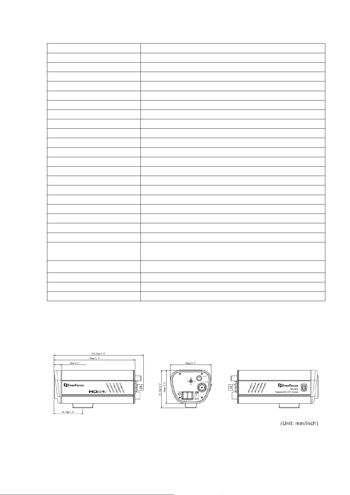
Dimensions (incl. BNC) 68mm(W) x 56mm(H) x 146mm(D) ; 2.7"(W) x 2.2"(H) x 5.7"(D)
Weight 0.4 kg ; 0.9 lbs
Operating Temperature 0°C~45°C ; 32°F~113°F (20%~80% Humidity)
Certifications FCC/CE
1.4 Dimensions
- 3 -
Page 5
2. NAMES AND FUNCTIONS OF PARTS
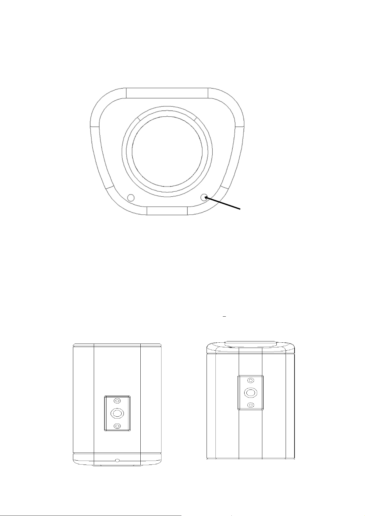
2.1 Front panel
The light sensor is for optional control of D/N switching levels in some applications. See section 5.6 for
details.
TAKE CARE NOT TO OBSTRCUT THIS OPENING
WITH THE BODY OF THE LENS!
Light Sensor
2.2 Top/Bottom Mounting
Using the two phillips head screws provided, the mounting bracket may be mounted to the top of
the camera body for suspending the camera; or, the brackets may be mounted to the bottom of the
camera body to support the camera.
Top Bracket
Bottom Bracket
- 4 -
Page 6

2.3 Back panel and connections
6
○
1
○
2
○
3
○
5
○
4
○
7
○
1
○
OSD Menu joystick: Use the joystick to move the cursor Upwards/Downwards. This is used to
select the item to be set. Tilt the stick to the right or left. This is used to select or adjust the
parameters of the selected item. Press in on the stick to enter the setup menu.
2
○
TV-Out
Connect to the TV-input of the Monitor by using a RCA connector.
3
○
HD-SDI Output: High-definition serial digital interface (BNC connector type). Connect to a video
device through a 75 Ohm type coaxial cable to the BNC female connector at the rear of the camera.
4
○
Video Out: a switch to select which video output is used for connection.
5
○
Power Input Terminal: Connect 12VDC/24VAC power.
- 5 -
Page 7

6
○
Power LED: The power LED lights up when power is ON.
7
○
DC Auto Iris Lens Connector: This connector is used to connect with the DC type auto iris lens
using a standard 4 pin male connector
Pin 1 Pin 2 Pin 3 Pin 4
Direct Drive Cnt- Cnt+ Drv+ Drv-
3
1
4
2
3. INSTALLATION
1. Unscrew/remove the cover cap from the lens mount.
2. If C mount lens is used, please add the C adaptor mount ring (the 5mm thick ring in
the accessory pack) between the lens and the mount. Please note: Failure to use a
spacer ring when attaching a C mount lens can damage the camera!
3. Mount the lens by turning it clockwise into the lens mount.
4. If you use an Auto Iris lens, connect the lens cable to the auto iris lens connector on
the side of the camera.
5. After mounting and connecting the camera, when making final focus adjustments,
remove the protective sheets from both sides of the ND filter provided; place the ND
filter in front of the lens to force the lens iris to open; then adjust the lens focus until
the best image is obtained.
6. Lock the lens focus by turning any clamping screws provided on the lens, then
remove the ND filter.
Mounting the lens -----------------5mm C Mount spacer (optional) shown
o--------------------
Light Sensor
TAKE CARE NOT TO OBSTRUCT THIS OPENING
WITH THE BODY OF THE LENS!
- 6 -
Page 8

4. OSD Menu & Configuration
Access the user setup menu screen:
I. Press inward on the end of the joystick
The menu screen will appear on the monitor.
II. Navigating with the joystick
Angle the joystick or to move the cursor up or down. Angle the joystick or to
adjust the mode or value of a setting.
III. Switching to sub-menu screens
When an item with sub-menu is selected, press inward on the end of the joystick to
switch to the sub-menu for further settings.
IV. Return to previous page
Press the SET button to return to previous page if the choice displayed is Return.
- 7 -
Page 9

Menu Tree
Lens — Manual ; DC
Shutter — Auto ; 1/50 ; 1/60 ; 1/100 ; 1/120 ; 1/250 ; 1/500 ; 1/700 ;
1/1000 ; 1/1600 ; 1/2500 ; 1/5000 ; 1/8000
Iris — 0.0EV ; +0.5EV ; +1.0EV ; +1.5EV ; +2.0EV ; -0.5EV ;
Exposure -1.0EV ; -1.5EV ; -2.0EV
AGC — High ; Middle ; Low ; Off
BLC — On ; Off
Anti-Flicker — Auto ; 50Hz ; 60Hz
Return
Auto WB
One push WB
Red — 0~100
White Balance Manual Blue — 0~100
Return
Indoor
Outdoor
Return
Auto
Day/Night Color
Black/White
Return
1080i
Resolution 720p
Display On / Display Off
Return
On
Camera Title Off
Return
Mirror — H_MIR ; V_MIR ; OFF
Special D-Effect Gamma — 0.45~1.00
- 8 -
Page 10

Neg_Image — On ; Off
Return
TV Out — NTSC ; PAL ; Return
English
German
Russian
Language French
Spanish
Trad. Chinese
Simp. Chinese
Japanese
Return
Default — Yes ; No
Return
Sharpness — 1~5
Image Adjust Brightness — 1~31
Contrast — 1~31
Return
- 9 -
Page 11

Press Set button to enter SETUP Menu. In SETUP menu, use the joystick to make settings. User
can do camera settings including Exposure, White balance, Day/Night, Special and Image adjust.
Please select the item by moving the joystick UP or DOWN then press SET to enter the settings.
Move the joystick to the last option which is “Return” to return to live view.
4.1 Exposure
In this section, user can do camera settings including Lens, Shutter, Iris, AGC, BLC and Anti-flicker.
Please select the item by moving the joystick UP or DOWN. Select “Return” to return to the previous
menu.
4.1.1 Lens
Select the type of the lens used (Manual/DC type) by moving the joystick LEFT or RIGHT.
NOTE:
The brightness of the screen can be adjusted in DC mode in Lens Level. The level can be adjusted
from 1 to 31.
4.1.2 Shutter
Select the shutter mode by moving the joystick LEFT or RIGHT.
Select from Auto,1/50,1/60,1/100,1/120,1/250,1/500,1/700,1/1000,1/1600,1/2500,1/5000 and 1/8000.
NOTE:
When selecting a DC lens, the shutter speed is fixed as 1/60 for NTSC and 1/50 for PAL.
4.1.3 Iris
Select the iris mode by moving the joystick LEFT or RIGHT.
The level can be adjusted from 0.0EV, +0.5EV, +1.0EV, +1.5EV, +2.0EV, -0.5EV, -1.0EV, -1.5EV and
-2.0EV.
4.1.4 AGC (Auto Gain Control – basic low light signal amplification)
Select the level you would like to choose by moving the joystick LEFT or RIGHT. The more the level of
gain increases, the brighter the screen, but the level of noise increases as well. Please select from High,
Middle, Low and Off.
4.1.5 BLC
Select “On” or “Off” by moving the joystick LEFT or RIGHT. Video gain can be adjusted automatically to
correct the exposure of subjects that are in front of a bright light source.
- 10 -
Page 12

4.1.6 Anti-Flicker
Selections are Auto, 50Hz and 60Hz. Camera will auto adjust the shutter to reduce the flicker caused by
fluorescent light when manual lens is used.
4.2 White Balance Control
The screen color can be adjusted by using the White Balance function.
Please select one of the 5 modes below by moving the joystick UP or DOWN then press “Set” button to
save the setting:
AWB
This mode can be used within the color temperature range from 2,500°K to 10,000°K.
One Push WB
Enable one push trigger for white balance mode. This holds the white balance at a specific color
temperature until the next command trigger is given.
Manual
The manual adjustment mode enables a more precise adjustment. Set the suitable color
temperature, and increase or decrease the red and blue color values at the same time while
checking the color changes of the objects in view.
Return: Select “Return” to saves all settings in this menu and returns to the previous menu.
Indoor
Select this option when the color temperature is 4,000°K.
Outdoor
Select this option when the color temperature is 5,000~6,500°K.
Select “Return” to return to the previous menu.
4.3 Day/Night
These settings control the operation of the camera when the illumination level changes. Choices are
Color at all times; B/W at all times; or color when illumination is bright, switching to B/W in low light.
Please select one of the 3 modes below by moving the joystick UP or DOWN then press “Set” button to
save the setting:
AUTO: The picture switches to color in a normal (bright) environment and switches to B/W
when the ambient illumination is low. The switching point is determined by the AGC level.
COLOR: The picture is always displayed in color, even at low light levels.
B/W: The picture is always displayed in B/W.
Select “Return” to return to the previous menu.
- 11 -
Page 13

NOTE:
AGC selection must be set as middle or high in order to employ the auto switching function.
4.4 Special
In this section, user can do special settings including Resolution, Camera Title, D-Effect, TV-Out,
Language and Default. Please select the item by moving the joystick UP or DOWN then press SET to
enter the settings. Select “Return” to return to the previous menu.
4.4.1 Resolution
1. Select camera resolution from 1920x1080i and 1280x720p by moving the joystick UP or DOWN
then press “Set” button to save the setting
2. Display On: Press “Set” to switch between On/Off, whether to show current resolution.
Select “Return” to return to the previous menu.
4.4.2 Camera Title
Select “On” by moving the joystick UP or DOWN then press “Set” to enter the setting. Input a camera
title by moving the joystick UP and Down, cursor will navigate among characters and numbers. The
available letters are A-Z and 0-9. Press “Set” key to confirm. Move the joystick Left and Right to move
the cursor among the same level.
Select “Off” by moving the joystick UP or DOWN then press “Set” to disable the camera title display.
Select “Return” to return to the previous menu.
4.4.3 D-Effect
In this section, user can do camera settings including Mirror
the item by moving the joystick UP or DOWN. Select “Return” to return to the previous menu.
4.4.3.1 Mirror
Select one of the 3 modes below by moving the joystick LEFT or RIGHT.
-Off: Disable the effects.
-H-MIR: Sets a horizontal image inversion.
-V-MIR: Set a vertical image inversion.
4.4.3.2 Gamma
Select the Gamma level by moving the joystick LEFT or RIGHT.
The level can be adjusted from 0.45 up to 1.0.
, Gamma and Neg_Image. Please select
- 12 -
Page 14

4.4.3.3 NEG_IMAGE
Select Neg_Image On or Off by moving the joystick LEFT or RIGHT. Allows user to create a negative of
the original image. A negative image is a tonal inversion of a positive image, in which light areas appear
dark and vice versa. A negative color image is additionally color reversed, with red areas appearing
cyan, greens appearing magenta and blues appearing yellow.
4.4.4 TV standard
Select video format of TV standard by moving the joystick UP or DOWN then press “Set” button to save
the setting. Selectable from NTSC and PAL format.
Select “Return” to return to the previous menu.
4.4.5 Language
Select OSD language. EQH5200 camera supports multiple languages inc
luding English, German,
Russian, French, Spanish, Traditional Chinese, Simplified Chinese and Japanese. Move the joystick UP
or DOWN to select a language then press “Set” button to save the setting.
Select “Return” to return to the previous menu.
4.4.6 Default
Select “Y
es” to load system settings to default factory values. Or select “No” to disregard this option.
4.5 Image Adjust
In this section, user can adjust Sharpness, Brightness and Contrast of the image. Please select the item
by moving the joystick UP or DOWN. Select “Return” to return to the previous menu.
4.5.1 Sharpness
Select the sharpness level by moving the joystick LEFT or RIGHT. The contour of the video image
becomes cleaner and more easily distinguished as the level of Sharpness increases. If the level is set
too high, it may affect the video image and cause noise. The available range of level is 1~5.
4.5.2 Brightness
Select the brightness level by moving the joystick LEFT or RIGHT. To increase or decrease object
brightness of images. It is adjustable from 1~31.
4.5.3 Contrast
Select the contrast level by moving the joystick LEFT or RIGHT. To increase or decrease object contrast
of images. It is adjustable from 1~31.
- 13 -
Page 15

Y
Headquarter Office
12F, No.79 Sec.1 Shin-Tai Wu Road,
Hsi-Chi, Taipei, Taiwan
Tel: +886-2-26982334
Fax: +886-2-26982380
Beijing office
Room 609,Technology Trade Building.
Shangdi Information Industry Base,
Haidian District,Beijing China
Tel: +86-10-62971096
Fax: +86-10-62971423
European Office
Albert-Einstein-Strasse 1,
D-46446 Emmerich, Germany
Tel: +49-2822-9394-0
Fax: +49-2822-939495
USA California Office
1801 Highland Ave. Unit A
Duarte, CA 91010 ,U.S.A
Tel: +1-626-844-8888
Fax: +1-626-844-8838
India Office
Japan Office
5F Kinshicho City Building,2-13-4 Koto-bashi,
Sumida-Ku,Tokyo,130-0022,Japan
Tel: +81-3-5625-8188
Fax: +81-3-5625-8189
USA New York Office
415 Oser Ave Unit S
Hauppauge, NY 11788
Sales: +1-631-436-5070
Fax: +1-631-436-5027
Suite 803, 8th Floor,
Housefin Bhavan,
C-21 Bandra Kurla Complex,
Bandra (East), Mumbai 400 051
Tel: +91 22 6128-8700
our EverFocus product is designed and
manufactured with high quality materials and
components which can be recycled and reused.
This symbol means that electrical and electronic
equipment, at their end-of-life, should be
disposed of separately from your household
waste.
Please, dispose of this equipment at your local
community waste collection/recycling centre.
In the European Union there are separate
collection systems for used electrical and
electronic product.
Please, help us to conserve the environment we
live in!
Ihr EverFocus Produkt wurde entwickelt und
hergestellt mit qualitativ hochwertigen
Materialien und Komponenten, die recycelt und
wieder verwendet werden können.
Dieses Symbol bedeutet, dass elektrische und
elektronische Geräte am Ende ihrer
Nutzungsdauer vom Hausmüll getrennt
entsorgt werden sollen.
Bitte entsorgen Sie dieses Gerät bei Ihrer
örtlichen kommunalen Sammelstelle oder im
Recycling Centre.
Helfen Sie uns bitte, die Umwelt zu erhalten, in
!
der wir leben
P/N: 4605XQ5200001AR
- 14 -
 Loading...