

Page 1
HD CCTV
Digital Video Camera
OPERATION MANUAL
EQH5000
Before attempting to connect or operate, please read and follow these instructions.
Page 2

CONTENTS
1. CAUTIONS
2. FEATURES
3. EQUIPMENT AND ACCESSORIES
4. CAMERA COMPONENT DESCRIPTION
5. INSTALLATION
6. DIMENSIONS
7. SPECIFICATIONS
8. DIGITAL INPUT/OUTPUT CIRCUIT (Future use)
9. OSD MANUAL
3
Page 3

1. CAUTIONS
This device complies with Part 15 of the FCC Rules.
Operation is subject to the following two conditions;
1. This device may not cause harmful interference.
2. This device must accept any interference received,
including interference that may cause undesired operation.
Note
This equipment has been tested and found to comply with the limits for a Class A digital
device, pursuant to part 15 of the FCC Rules. These limits are designed to provide
reasonable protection against harmful interference when the equipment is operated
in a commercial environment. This equipment generates, uses, and can radiate radio
frequency energy and, if not installed and used in accordance with the instruction
manual, may cause harmful interference to radio communications. Operation of this
equipment in a residential area is likely to cause harmful interference in which case the
user will be required to correct the interference at his own expense.”
WARNING
This is a class A product. In a domestic environment this product may cause radio
interference in which case the user may be required to take adequate measures.
Caution
Any changes or modications in construction of this device which are not expressly
approved by the party responsible for compliance could void the user’s authority to
operate the equipment.
1. A regulated DC12V 1A power supply is recommended for use with this camera
for the best picture and the most stable operation.
An unregulated power supply can cause damage to the camera.
If an unregulated power supply is used, product warranty will be Void.
2. It is recommended that the camera is used with a system that has an HDCCTV quality
75 video impedance level.
3. Do not attempt to disassemble the camera to gain access to the internal components.
Refer servicing to your dealer.
4. Never face the camera towards the sun or any bright or reective light, which may
cause smear on the picture and possible damage to the CCD.
5. Do not remove the serial number sticker.
6. Do not expose the camera to rain or other type of liquid.
4
Page 4
1. CAUTIONS
Correct Disposal of This Product
(Waste Electrical & Electronic Equipment)
(Applicable in the European Union and other European countries with
separate collection systems)
This marking shown on the product or its literature, indicate that it should not
be disposed with other household wastes at the end of its working life. To
prevent possible harm to the environment or human health from uncontrolled
waste disposal, please separate this from other types of wastes and recycle it
responsibly to promote the sustainable reuse of material resources.
This product should not be mixed with other commercial wastes purchased this
product, or their local government ofce, for details of where and how they can
take item for environmentally safe recycling.
Business users should contact their supplier and check the terms and
conditions of the purchase contract.
Household users should contact either the retailer where they for disposal.
5
Page 5

2. FEATURES
High Resolution
•
1/3˝ SONY Progressive Color CMOS Sensor,
1280x720 30fps
• Supports Various Digital Video Output
720p 30, 720p 60
720p 25, 720p 50
• Video Outputs
Primary HD-SDI (BNC)
Test/Setup TV Out (BNC), NTSC /PAL selectable
• S/N Ratio :
• OSD menu for setup and configuration
• Lens Control
Manual Iris
DC Iris
• Provides True Day/Night Capability with Motorized IR Cut Filter
Max 50dB
• Accepts CS Mount Lenses :
• Power Source :
DC 12V
Adapter included for C-Mount Lens
6
Page 6
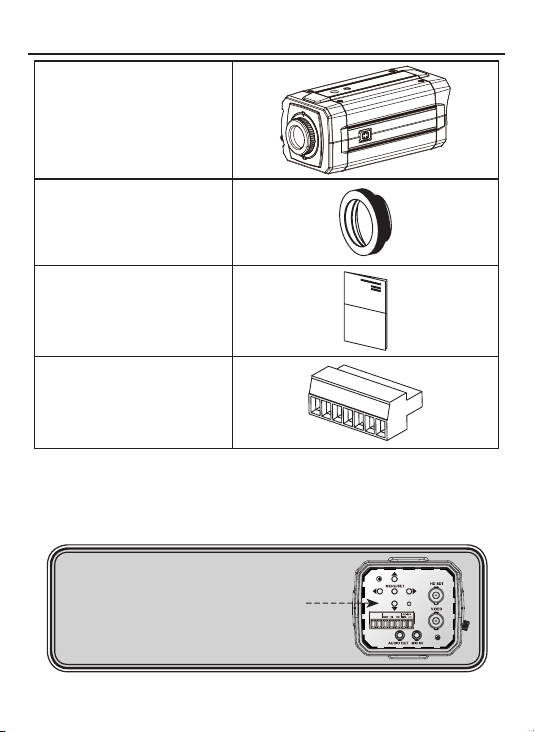
3. EQUIPMENT AND ACCESSORIES
HD CCTV
Digital Video Camera
C-MOUNT ADAPTOR RING
OPERATION MANUAL
TERMINAL BLOCK
NOTE
*
PLEASE REMOVE PROTECTION FILM
7
Page 7
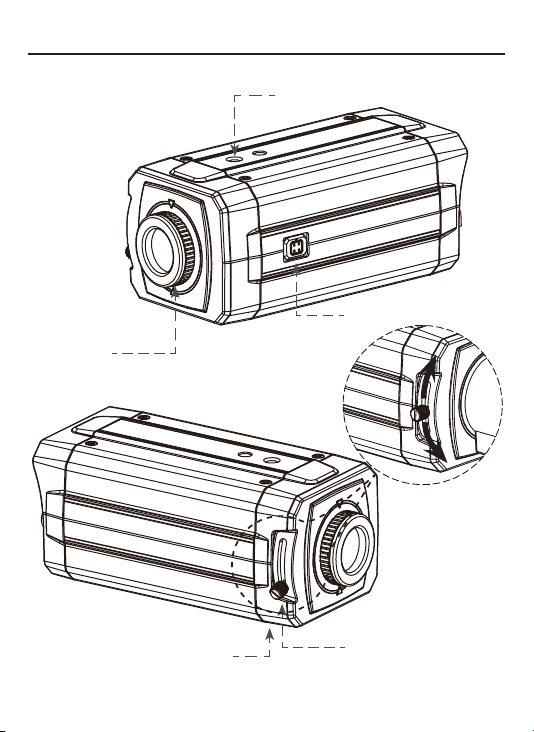
4. CAMERA COMPONENT DESCRIPTIONS
• FRONT
MOUNTING HOLE(1/4"-20 UNC)
AUTO IRIS JACK
C-MOUNT
ADAPTOR RING
(Optional - use for C-Mount lens only)
MOUNTING HOLE(1/4"-20 UNC)
BACK FOCUS CONTROL LEVER
8
Page 8
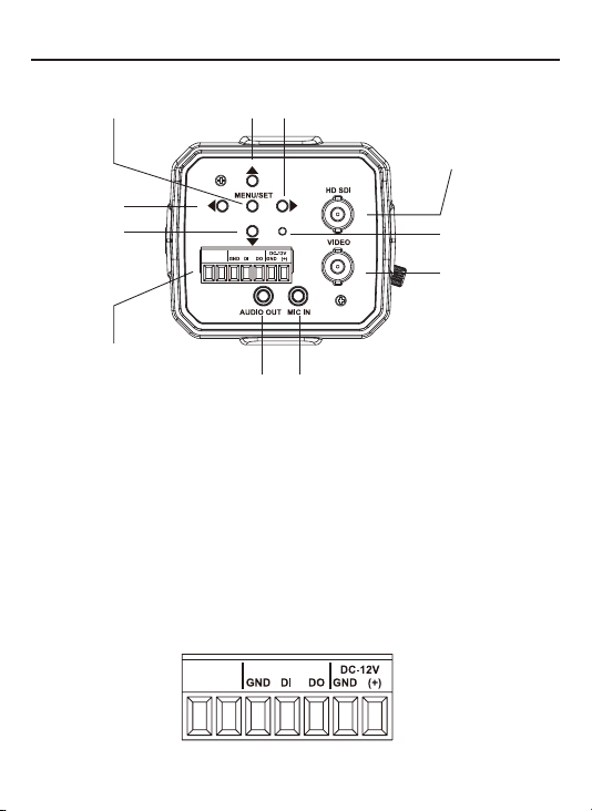
4. CAMERA COMPONENT DESCRIPTIONS
• BACK
① ②
④
③
⑪
. MENU SET BUTTON
①
MENU NAVIGATION BUTTONS
. UP BUTTON
②
. DOWN BUTTON
③
. LEFT BUTTON
④
. RIGHT BUTTON
⑤
. POWER LED
⑥
. SDI OUT BNC
⑦
. VIDEO OUT BNC
⑧
. MIC IN JACK(Future Feature)
⑨
. AUDIO OUT JACK(Future Feature)
⑩
. TERMINAL (POWER, Digital Input/Output) “Note : Digital input and Output for Future use”
⑪
⑤
⑦
⑥
⑧
⑨⑩
9
Page 9
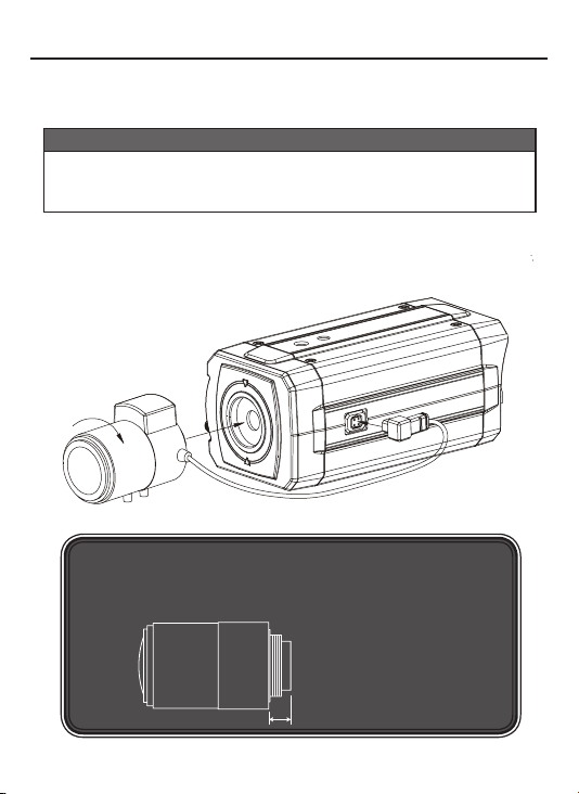
5. INSTALLATION
• LENS CONNECTION
Mega Pixel Lenses are sold separately. Lenses such as a DC auto iris lens,
CS-Mount lens and C-Mount lens can be used ( adapter included for C-Mount Lens).
NOTE
• Please keep the lens clean.
• Any foreign objects and Finger marks on the lens can cause
inferior image quality in low light level conditions.
After attaching the lens to the camera please insert the connection plug from the DC
auto iris lens cable into the auto lens connector, which is located on the side of the
camera
NOTE
*
When using a CS Mount Lens, you can attach it directly to camera,
If useing a C Mount lens, you must attach the ring spacer provided,
otherwise it will crack the image sensor.
C-mount lens : 10mm or less
CS-mount lens : 5mm or less
10
Page 10

5. INSTALLATION
Installation of C-Mount Lens
Installation of CS-Mount Lens
C to CS-MOUNT ADAPTOR RING
Lens
Lens
11
Page 11

5. INSTALLATION
• CONNECTION
BNC FEMALE
VIDEO
12
TO HD SDI IN
DC12V REGULATED
POWER SUPPLY
HDCCTV DVR
OR OTHER
HDCCTV SIGNAL
EQUIPMENT
TO VIDEO IN
HANDHELD
Page 12

6. DIMENSIONS
Unit: mm(inch)
MOUNTING HOLE
(1/4"-20 UNC, Depth 5)
30(1.18)
72.58(2.86)
66(2.60)
C-MOUNT ADAPTOR RING
(Optional use for C-Mount Lenses only)
145(5.71) / (C-Mount)
138.55(5.45) / (CS-Mount)
AUTO IRIS JACK
MOUNTING HOLE
13
Page 13

7. SPECIFICATION
Image Device
Effective Pixels 1329 (H) x 1049 (V) 30fps
Unit cell size 3.63um (H) x 3.63um (V)
Video output mode
H.Resolution
Minimum illumination 1.0 Lux
S/N Ratio
Shutter speed
Min. Exposure Time 110.86us (1/9020 sec)
Flickerless
True Day/Night
White Balance
BLC
Lens Control
OSD Menu
Power
Consumption
Dimension (W x H x D)
Weight (g / lb)
Lens Mount
Conformity
Temperature/Humidity
(non-condensing)
Specications and designs are subject to change without notice for improving the functionality of this product.
1/3” SONY Mega-Pixel Color Progressive CMOS
HDCCTV : 720p 30, 720p 60, 720p 25, 720p 50
TV Out : NTSC / PAL selectable
More than 800 TV Lines
Max 50dB
Auto / Manual selectable
Off / 60Hz(50Hz) selectable
IR Cut /Pass Filter change
ATW / Push / Manual
On/Off (by OSD)
Manual Iris, DC Iris
Yes
DC 12V
Max 500mA
72.5mm x 66mm x 138.5mm / 2.86inch x 2.60inch x 5.45inch
410g / 0.90lb
CS/C-mount
CE, FCC
Operation : Celsius -10~50 (Fahrenheit 14~122) / 20~80%
Storage :Celsius -20~70 (Fahrenheit -4~158) / 20~95%
14
Page 14

8. DIGITAL INPUT/OUTPUT
• Digital Input Port (Future Feature, Use for CDS Mode Only)
Day and Night
CAMERA
R:1.5K
CDS MODE
EXTERNAL DEVICE
DI
Sensor Input
(0~3.3V)
MicroController
A/D Port
10bit resolution,
Vtop = 3.3V, Vbot = 0V
GPIN PORT
(3.3V)
External CDS is only active when day and night mode is set to EXT Mode in the OSD.
CDS : External device to control day and night status
Digital Input Port
• Digital Output Port ( Future Feature)
CAMERA EXTERNAL DEVICE
R:270
15
3.3V
Photo
Coupler
R:10K
Digital Output Port
DO
Digital Output
(0/3.3V)
MicroController
GPOUT PORT
(3.3V)
Page 15

9. OSD MANUAL
• Menu structure
- Main Menu
WHITE BALANCE
DAY / NIGHT
- VIDEO OUT Menu
VIDEO OUT SDI FORMAT
TV OUT FORMAT NTSC / PAL
VIDEO OUT
LENS
EXPOSURE
IMAGE
SPECIAL
720p 30Hz / 720p 60Hz
720p 25Hz / 720p 50Hz
16
Page 16

8. OSD MANUAL
- LENS Menu
LENS LENS TYPE
BRIGHTNESS 0 ~ 127
IRIS SPD 0 ~ 112
- EXPOSURE Menu
EXPOSURE BRIGHTNESS
DC IRIS / MANUAL IRIS
DC IRIS
0 ~ 127
SHUTTER MODE
SHUT LEVEL(Shutter Level)
AGC MAX
BLC
17
0 ~ 150
ON / OFF
AUTO / MANUAL
/ FLK 60Hz(FLK 50Hz)
MANUAL
0~215
Page 17

9. OSD MANUAL
- WHITE BALANCE Menu
WHITE BALANCE MODE
ATW / PUSH / MANUAL
MANUAL
- DAY / NIGHT Menu
DAY / NIGHT MODE
NIGHT LEVEL 0 ~ 127
- IMAGE Menu
IMAGE SHARPNESS
R GAIN
B GAIN
DAY LEVEL 0 ~ 127
IMAGE FLIP
DNR
GAMMA
0 ~ 255
0 ~ 255
COLOR / AUTO / EXT / BW
AUTO / EXT
0 ~ 15
OFF, H FLIP, V FLIP, H/V FLIP
OFF, LOW, MID, HIGH
OFF, 1.0, 1.8, 2.2, 2.6
18
Page 18

9. OSD MANUAL
- SPECIAL Menu
SPECIAL SYSTEM INFO
USER SET
COMM/GPIO SET
FOCUS MODE ON / OFF
LANGUAGE
SAVE USER SET
LOAD USER SET
CLEAR USER SET
FACTORY RESET
CAMERA RESET
RS485 Address
GP IN Status
GP OUT Control
19
0~255
LOW / HIGH
Page 19

9. OSD MANUAL
• ICONS
- : Value adjustment(use LEFT/RIGHT button).
- : Select Sub Menu(use SET button).
- : Execution command(use SET button).
- : Return to previous menu.
- : Menu OFF.
- : Information.
The [SETUP] menu will show up when you push the SET button.
• Main Menu
[ SETUP ]
VIDEO OUT
LENS
EXPOSURE
WHITE BALANCE
DAY / NIGHT
IMAGE
SPECIAL
EXIT
SAVE & EXIT
720p 60Hz
DC IRIS
AUTO
AUTO
- VIDEO OUT :
- LENS :
- EXPOSURE :
- WHITE BALANCE :
- DAY / NIGHT :
- IMAGE :
- SPECIAL :
- EXIT :
- SAVE & EXIT :
Select SDI Out format and TV Out format.
Select the IRIS TYPE and adjust IRIS control value.
Adjust Exposure control.
Adjust White balance control.
Day / Night control.
Apply Image processing effects.
System setting, IO setting, USER SET setting
Close OSD Menu.
Save and Close OSD Menu. These settings are
loaded and applied automatically when the Camera
is power on.
20
Page 20

9. OSD MANUAL
•
Video Out
[ VIDEO OUT ]
SDI FORMAT
TV OUT FORMAT
ESC
EXIT
SAVE & EXIT
•
LENS
[ LENS ]
LENS TYPE
BRIGHTNESS
IRIS SPD
ESC
EXIT
SAVE & EXIT
720p 60Hz
NTSC
DC IRIS
123
- SDI Format
Select SDI output Formats – 720p 30Hz,
720p 60Hz, 720p 25Hz and 720p 50Hz.
- TV Out Format
Select NTSC / PAL.
Note : NTSC or PAL Video Format can be
selected by pressing the RIGHT Button even
when the OSD Menu is turned off
- ESC
Back to the previous.
- LENS TYPE
Using Left / Right button, Select DC IRIS or
MANUAL IRIS.
- BRIGHTNESS
1
This menu appeared on screen when DC IRIS
is selected.
Using Left / Right button, adjust Brightness
value.
- IRIS SPD
This menu appears on screen when DC IRIS
is selected.
Using Left / Right button, adjust Iris speed
value.
21
Page 21

9. OSD MANUAL
•
EXPOSURE
[ EXPOSURE ]
BRIGHTNESS
SHUTTER
AGC MAX
BLC
ESC
EXIT
SAVE & EXIT
•
SHUTTER (Sub Menu)
AUTO
[ SHUTTER ]
MODE
SHUT LEVEL
ESC
EXIT
SAVE & EXIT
- SHUT LEVEL (Shutter Level)
This menu can be accessed when the Shutter Speed is set to MANUAL.
MANUAL
- BRIGHTNESS
Same as the BRIGHTNESS value in LENS
123
Menu. Using Left / Right button, adjust
Brightness value.
10
OFF
- SHUTTER
Using Set button, go to the SHUTTER sub
menu.
- AGC MAX
Using Left / Right button, adjust AGC Max
value.
- BLC
Using Left / Right button, select on/off of BackLight Compensation Control.
- MODE
Using Left / Right button, select Shutter Control
modes – AUTO, MANUAL and FLK 60Hz
1
(FLK 50Hz).
AUTO Auto Exposure mode
MANUAL Manual Exposure mode
FLK 60Hz (FLK 50Hz) Flickerless mode (Default)
Use the Left / Right button to adjust the shutter speed control level.
Instead of using the default conventional shutter speed of 1/60,
you may choose other speeds. The speeds corresponding to the value of shutter
level are listed below.
Shutter
1/50 1/60 1/100 1/120 1/250 1/500 1/700 1/
Speed
Level 178 169 142 135 105 65 46 32 20 12 6 4 3
10001/16001/25001/50001/70001/10000
22
Page 22

9. OSD MANUAL
•
WHITE BALANCE
[ WHITE BALANCE ]
MODE
R GAIN
B GAIN
ESC
EXIT
SAVE & EXIT
- MODE
Using Left / Right button, select White balance modes – ATW, PUSH
and MANUAL.
ATW Auto Trace White Balance mode
PUSH White Balance Push Lock mode (Auto White Balance Control & Lock)
MANUAL Manual White Balance mode
- R GAIN
This menu appears on screen when MANUAL is selected.
Using Left / Right button, adjust Red Gain.
-B GAIN
This menu appears on screen when MANUAL is selected.
Using Left / Right button, adjust Blue Gain.
* NOTE
R GAIN and B GAIN is correlated with the G GAIN internally, so the R GAIN and B
GAIN may increase or decrease with the other color gain.
MANUAL
100
100
23
Page 23

9. OSD MANUAL
• Day / Night
[ DAY / NIGHT ]
MODE
DAY LEVEL
NIGHT LEVEL
ESC
EXIT
SAVE & EXIT
- MODE
Using Left / Right button, select TDN(True Day & Night) modes – AUTO,
EXT, COLOR, and BW.
AUTO Controlled by AGC level in the processor. (AGC Type)
EXT Controlled by signal from CDS sensor. (CDS Type)
COLOR Fixed Day State. Color Image.
BW Fixed Night State. BW Image.
- DAY/Night Levels
This menu can be displayed by selecting AUTO or EXT in the MODE Menu.
The Day Level and Night Level thresholds function independently from each other.
- DAY LEVEL
The threshold of change from B&W Mode to Color Mode can be adjusted with values
between 0 - 127. A lower value will prevent the camera from switching to Color until
the scene becomes brighter.
- NIGHT LEVEL
The threshold of change from Color Mode to B&W Mode can be adjusted with values
between 0 - 127. A higher value will prevent the camera from switching to B&W until
the scene becomes darker.
Note: These is a built in offset between the Day and Night Level to prevent a
switching level conflict. The effective Day level can not be set lower than
the Night level
AUTO
100
50
24
Page 24

9. OSD MANUAL
• IMAGE
[ IMAGE ]
SHARPNESS
IMAGE FILP
DNR
GAMMA
ESC
EXIT
SAVE & EXIT
OFF
OFF
0
1.0
- SHARPNESS:
- IMAGE FLIP:
- DNR:
- GAMMA:
Using Left / Right button, adjust sharpness value.
Using Left / Right button, select Flip modes – OFF, H FLIP, V FLIP and H/V FLIP.
Using Left / Right button, select Digital Noise Reduction Modes - OFF, LOW, MID, HIGH.
Using Left / Right button, adjust gamma control setting.
• SPECIAL
[ SPECIAL ]
SYSTEM INFO
USER SET
COMM / GPIO SET
FOCUS MODE
• LANGUAGE
ESC
EXIT
SAVE & EXIT
[ SYSTEM ]
• TYPE
• MODULE ID
• CAMERA VER
• IF F/W VER
ESC
EXIT
HD-SDI CAMERA
ADDR 0
OFF
ENGLISH
00_0000
02.02_0000R05
01.00_1110R00
[X]
- SYSTEM INFO
Display Camera Version, SDI IF F/W Version &
other information.
25
Page 25

9. OSD MANUAL
- USER SET
Using Set button, display [USER SET] sub menu.
- COMM/GPIO SET
Using Set button, display [COMM/GPIO SET] sub menu.
- FOCUS MODE
In focus mode, the iris becomes fully open, electronic shutter controls the light
level, and the TV out screen zooms into the center in order to make focusing
easier. When in Focus Mode, the OSD Menu is not displayed. The OSD Menu can
be toggled on and off using the Left / Right button.
> TV Out Image
FOCUS MODE OFF FOCUS MODE ON
- LANGUAGE
Select OSD Language. (Only English is available, currently)
• USER SET (Sub Menu)
- SAVE USER SET
[ USER SET ]
SAVE USER SET
LOAD USER SET
CLEAR USER SET
FACTORY RESET
CAMERA RESET
ESC
EXIT
Saves a copy of the current configuration set by the user into
a separate memory area. If user set data has been saved,
an [O] mark is displayed and if not, an [X] mark is displayed.
User Set settings can NOT be loaded automatically when
[X]
the camera is powered on. They can only be loaded
manually via the “LOAD USER SET” OSD choice. To make
the values in a User Set become the configuration loaded
when the camera is powered on, first load that User set,
then choose “SAVE AND EXIT” in any of the OSD Screens;
the current User Set OSD Settings will be written to the
power on configuration. These steps effectively copy a User
Set to the power on configuration.
- LOAD USER SET
Load the saved user set, and applies to Camera.
- CLEAR USER SET
Clear all saved user set.
- FACTORY RESET
Clear all setting and initialize to factory setting.
Clear user set.
- CAMERA RESET
Reboot the Camera.
26
Page 26

9. OSD MANUAL
• COMM/GPIO SET (Sub Menu)
[ COM / GPIO SET ]
RS485 Address (Future Feature)
• GP IN Status
GP OUT Control
ESC
EXIT
SAVE & EXIT
- RS485 Address
Future Feature.
- GP IN Status ( CDS Mode Only Digital input Future Feature)
If the OSD is set to the EXT mode in the [DAY/NIGHT] menu, this port is used to
connect to a photo-sensor.
- GP OUT Control (Future Feature)
For control of an external device by the camera.
LOW
LOW
.
27
Page 27

EverFocus Electronics Corp.
Corporate Headquarters:
12F, No.79 Sec. 1 Shin-Tai Wu Road,
Hsi-Chih, Taipei, Taiwan
TEL: +886-2-26982334
FAX: +886-2-26982380
www.everfocus.com.tw
marketing@everfocus.com.tw
U.S.A - California Ofce:
1801 Highland Avenue Units A & B
Duarte, CA 91010
TEL: +1-626-844-8888
FAX: +1-626-844-8838
www.everfocus.com
sales@everfocus.com
China Office:
Room 609, Technology Trade Building,
Shangdi Information Industry Base,
Haidian District, Beijing, China 100085
TEL: +86-10-62973336~39
FAX: +86-10-62971423
www.everfocus.com.cn
marketing@everfocus.com.cn
U.S.A - New York Office:
415 Oser Avenue Unit S
Happauge, NY 11788
TEL: +1-631-436-5070
FAX: +1-631-436-5027
www.everfocus.com
sales@everfocus.com
Europe - Germany Ofce:
Albert-Einstein-Strasse 1,
D-46446 Emmerich, Germany
TEL: +49-2822-93940
FAX: +49-2822-939495
www.everfocus.de
info@everfocus.de
India Ofce:
Suite 803, Housen Bhavan, C-21,
Bandra Kurla Complex, Bandra (East),
Mumbai 400051. India.
TEL: +91-222-444-8791
FAX: +91-222-444-8790
www.everfocus.in
Your EverFocus product is designed
and manufactured with high quality
materials and components which can
be recycled and reused.
This symbol means that electrical and
electronic equipment, at their end-oflife, should be disposed of separately
from your household waste.
Please, dispose of this equipment at
your local community waste
collection/recycling centre.
In the European Union there are
separate collection systems for used
electrical and electronic product.
Please, help us to conserve the
environment we live in!
Ihr EverFocus Produkt wurde
entwickelt und hergestellt mit qualitativ
hochwertigen Materialien und
Komponenten, die recycelt und wieder
verwendet werden können.
Dieses Symbol bedeutet, dass
elektrische und elektronische Geräte
am Ende ihrer Nutzungsdauer vom
Hausmüll getrennt entsorgt werden
sollen.
Bitte entsorgen Sie dieses Gerät bei
Ihrer örtlichen kommunalen
Sammelstelle oder im Recycling Centre.
Helfen Sie uns bitte, die Umwelt zu
erhalten, in der wir leben!
Japan Office:
5F Kinshicho city Building,
2-13-4 Koto-Bashi,
Sumida-Ku, Tokyo, 130-0022 Japan
TEL: +81-3-5625-8188
FAX: +81-3-5625-8189
www.everfocus.co.jp
info@everfocus.co.jp
UK Office:
Unit 12 Spitfire Business Park
Hawker Road
Croydon, CR0 4WD
London: 0845 430 9999
Telford: 0845 430 8888
Fax: 020 8649 9907
uk.support@EverFocus.com
28
 Loading...