

Page 1
INSTRUCTION MANUAL
1/3” W-Dynamic High Resolution Color Camera
EQ600 WDII
Version 1.0
About this manual
Before installing and using this camera, please read this manual carefully.
Be sure to keep it handy for later reference.
Page 2

Safety Warning
1. Read manual carefully before installing the unit.
Please read this manual first for correct installation and operat ion.
2. Never install the camera on a ceiling that cann ot hol d i ts weight
The product may fall down to cause damages.
3. Do not install the camera near electric or magnet i c fi el ds.
Installed the camera away from TV, radio transmitter, magnet, electric motor, transformer, audio
speakers because the magnetic fields generate fro m above devices will distort the video image.
4. Always stop using when the product emits sm oke or abnormal heat
5. Never disassemble the camera nor put impurities in it
Disassembly or im purities may result in trouble or fire.
6. Never face the camera toward the sun.
Direct sunlight or severe ray may cause fatal damage t o sensor and internal circuit.
7. Keep the power cord away from wet and never touch the power cord with wet hands.
Touching the wet power cord with hands or touching the power cord with wet hands may result in
electric shock.
8. Never install the camera in areas exposed to water, oil or gas.
The water, oil or gas may result in fail ure, el ectric shock or file.
9. Cleaning
Do not touch the surface of sensor by hand directly. Use a soft cloth to remove the dirt from the
camera body. Use lens tissue or a cotton tipped applicator a nd etha no l to cl ean t he sensor a nd th e
camera lens.
10. Do not operate the camera beyond the specified temperature, humidity or power source
ratings.
Use the camera at temperatures within 0℃℃℃℃ ~ 40℃℃℃℃ and humidity below 90%. The input power
source is DC12V/AC24V.
Notice:The in formation in this manua l was current when published. The manufacturer reserves the
right to revise and improve it s product s. All specifications are therefore subjec t to change with out notic e.
Page 3

Table of Contents
1. Product Overview……….………………..……………..………………………….…….…2
1.1 Main Features.…..…………..………………………………………………..…………2
1.2 Content List………………………………………………………………………………2
1.3 Specifications……………..……….……………………………………………………..3
2. Back Panel Connections………… ……… ……….…………… … ………….……………. 4
3. Operation………………………………………………………..………………..……..…5~6
3.1 Setup Buttons…...………………………………………………………………..……...5
3.2 Display/Close the user setup menu screen…..………………………………………6
4. Main Menu Flow……..……… ….. …… ….. ……… …… …… …… … ……… …… …… ……7
5. Preset Mode……………..……………………………..…….………………………………8~9
5.1 User Setup Menu Flow….…………………………………………………………..….8
5.2 User Setup……………………………………………………………………………….9
6. Camera ID…… …… ……… ……… …… …………… ……… …..………………………10~11
6.1 Camera ID……………………………………………………………………………….10
6.2 ID Position……………………………………………………………………………….11
6.3 ID Color ………………………………………………………………………………….11
6.4 ID Background…………………………………………………………………………..11
7. Advanced Setup…………………………..…………..…….…………………………12~13
7.1 Auto IRIS…………………………………………………………………………….…..12
7.2 White Balance……………………………………………………………………..……12
7.3 LineLock…………………………………………………………………………………13
7.4 Viewing………………………………..………..…………………………………..14
8. Save/Restore…… ………… …………… ………… …………… ………… ……………. .…15
Appendix-A…Camera ID Character patterns……………………………………….……..17
Appendix-B…Factory Settings Chart……………………………………..………….…….18
1
Page 4

Product Overview
1. Product Overview
TM
By utilizing Digital Pixel System
improves the performance of surveillance camera in extreme lighting condit ions. Where traditional
CCD cameras have difficulty processing images in strong backlighting, the EQ600WDII processes
each pixel independently, correcting for the variations and providing the best possible image under
the lighting conditions.
1.1Main Features
1/3” Color DPS sensor
High resolution: Over 480 TV L ines/1.0lux and low speed shut ter up to 32x
Day/Night function
OSD function control
With programmable camera ID up to 12 characters
Compact stylish design fo r discret e observation
Free S/W for remote configuration through R S23 2 via PC
Image flip: Horizontal reve rse
1.2Content List
1/3” W-Dynamic High Res oluti on Co lor Ca mera u nit
User’s manual
Mini Din male connector cable for S-V id eo / R S-232
(DPS) sensor technology, the new EQ600WDII dramatically
2
Page 5

1.3 Specifications
Pickup Device 1/3” Color DPS sensor
Specifications
Picture Element
Horizontal Resol ution >480 TV lines
Sensitivity 1.0 Lux/ F=1.2 (50IRE col or)
Low Speed shutter Up to 32x(2,4,8,16,32)
S/N Ratio >48dB
Auto exposure: YES
Auto White Balance Yes, 2500K ~9500K
Back light compensation YES
Auto IRIS YES
Video Outputs 1.0Vp-p composite S-Video(Y/C output)
Auto Gain Control Yes
Day/Night function ON/OFF
Dynamic range 95dB typical, 120dB max
Synchronization Internal or Line Lock (AC input requ ired)
Image Flip Yes, Horizontal reverse
720(H) × 540(V)
Video Output: 1 Vp-p / 75 ohm composite, S-Video (Y/C output)
Imaging Syste m NTSC/ PAL
On Screen Display Yes
Power Source AC24V / DC12V
Operating Temperature
Power Consumption 7W max.
Dimensions (mm) 56 (W) x 68 (H) x101 (D)
Lens mount C/CS mount, DD Drive
0℃℃℃℃ ~ 40℃℃℃℃
3
Page 6
(7)
Back Panel Connecti ons
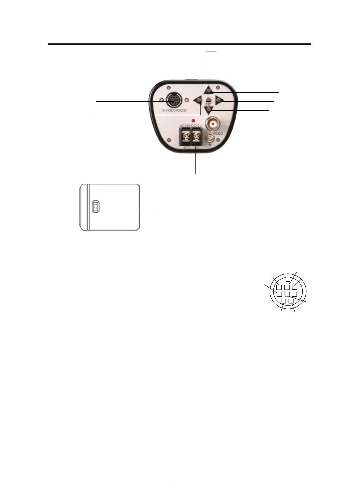
2. Back panel connections
(1)
(4)
(8)
(6)
(2)
(9)
(1)S-Video / RS-232 port:
Connect Mini Din Male Connector to S-Video / RS-232 port for better video output quality or
communication. Please refer to the pin assignment of the S-Video/ RS-232 port as below:
(2)AC24V/DC12V Compatible Input Terminal:
This power terminal is for connecting the AC24V/DC12V power supply cord
(3)Video Output Connector: Connect the video output of the camera to a color monitor or other
video devices through a 75 Ohm type coaxial cable with BNC female connector at backside of
the camera.
(4) Tact switcher for left cursor
(5) Tact switcher for down cursor
(6) Tact switcher for right cursor
(7) Tact switcher for up cursor
(8) Tact switcher for on-screen setting menu
(9) Auto Iris Lens Connector
This connector is used to connect with the auto iris lens by a 4 pin male connector
Pin 1 Pin 2 Pin 3 Pin 4
Video Drive +12V GND VD-IRIS GND
Direct Drive Cnt- Cnt+ Drv+ Drv-
GND
5V
C
RX
TX
Y GND
Y
C GND
4
Page 7
Operation
3.Camera Setup Operations
This camera utilizes an On Screen Display (OSD) user set up menu.
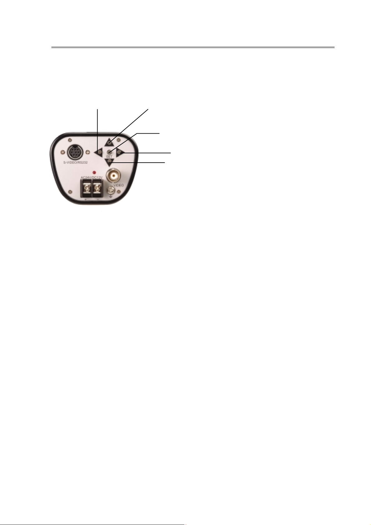
3.1 Setup Buttons: To set items on the user setup menu, use the following buttons on the back
panel.
①①①①
Up Button: This button is used to move t he cursor upwards. Use this button t o select an
②②②②
Down Button: This butto n is used to move the curs or dow nw ards. Use this button t o select
③③③③
Right Button: This button is used to move the cursor to the right. Use this button to select
④④④④
Left Button: This button is used to move the cursor to the left. Use this button to select or
⑤⑤⑤⑤
Set Button: This button is used to set the determined paramet ers. I f the item has its own
④④④④Left Button
Up Button
①①①①
⑤⑤⑤⑤Set Button
③③③③Right Button
②②②②Down Button
item or adjust the para meters.
an item or adjust the para meters.
or adjust the parameters of the se lect it em. The parameter c hanges each
time as this button is pressed.
adjust the parameters of the select it em. The parameter changes each time
as this button is pressed.
setting menu, press this but t on t o display the setting menu.
5
Page 8

n
Operation
3.2 Display/Cl ose the user setup menu screen
I. Press the SET button for 2 second
II. Using the cursor but ton
III. Switch to sub-menu screens
Note: For those select items with “…” sign in the end, they have the sub-menu for further
IV. Return to previous page
V. Close the menu scre en
SET
Butto
The Cursor Buttons & the SET Button
Highlighted
EWD600 MAIN MENU
> PRESETMODE INDOOR…
CAMERA ID OFF
ADVANCED SETUP …
SAVE/RESTORE…
EXIT MENU
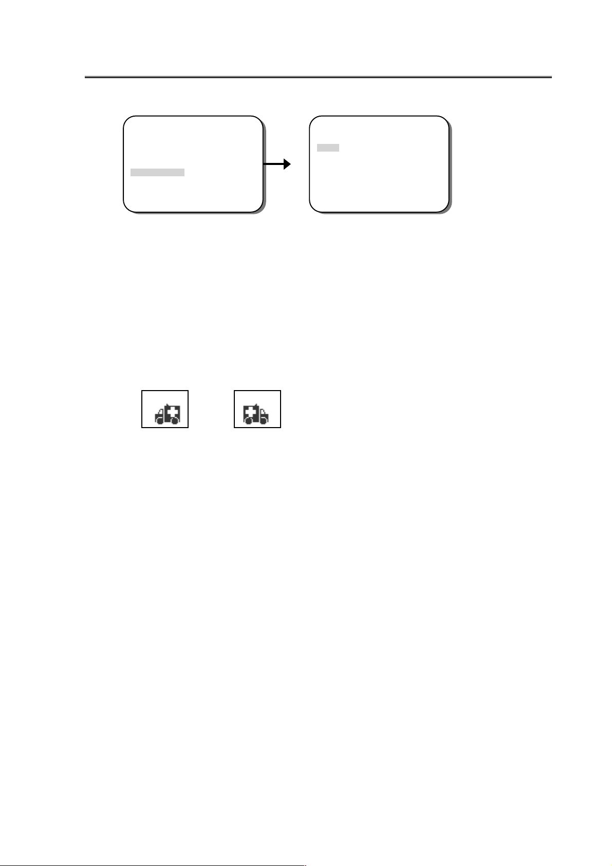
The menu screen will app ear on t he monitor as the block shown above.
Use the cursor button or to move t he cursor up or down. Use t he curs or b utton or
to adjust the mode or parameter of settings. The select item will be highlighted with a
gray color bar.
When the item with sub-menu is selected (highlighted), press t he SET button to switch to
the sub-menu for further settings. Please refer to the figure below.
EWD600 MAIN MENU
PRESET MODE INDOOR…
CAMERA ID OFF
> ADVANCED SETUP…
SAVE/RESTORE…
EXIT MENU
Main Menu
ADVANCED SETUP
> AUTO IRIS…
WHITE BALANCE…
LINELOCK…
VIEWING…
PREVIOUS PAGE
Sub-Menu
settings.
After setting, use the cursor buttons t o sel ect PREVIOUS PAGE, then press the SET
button.
To close the menu screen, use the cursor button to select EXIT MENU and press the
SET button. Or press the SET button for 1 sec.
6
Page 9

4. MAIN MENU FLOW
EWD600 MAIN MENU
> PRESETMODE INDOOR…
CAMERA ID OFF
ADVANCED SETUP…
SAVE/RESTORE…
EXIT MENU
MENU Flow
>PRESET MODE… <INDOOR…>
>CAMERA ID… < OFF>
> AUTO IRIS…
7
EWD600 MAIN MENU
<OUTDOOR…>
<FLUOR. ….>
<BACKLIGHT…>
EWD600 MAIN MENU
ADVANCED SETUP
WHITE BALANCE…
LINELOCK…
VIEWING…
PREVIOUS PAGE
SAVE/RESTORE
> RESTORE USER SETTINGS..
SAVE USER SETTINGS..
RESTORE FACTORY SETTINGS..
RESET CAMERA..
MENU REV. 0.1
PREVIOUS PAGE…
<USER…>
<ON…>
Page 10

5. PRESET MODE
EWD600 MAIN MENU
>PRESET MODE <INDOOR…>
<OUTDOOR…>
<FLUOR. ….>
<BACKLIGHT…>
<USER…>
5.1 USER SETUP Menu Flow
USER SETUP
>CAMERAVIEW SHADOW
SLOW SHUTTER OFF
WDR MODE AUTO…
METER MODE NORMAL…
PREVIOUS PAGE
I. Select the suitable settings, such as
INDOOR, OUTDOOR, FLUOR. or
BACKLIGHT based on the installation
environment.
II. Press the SET button to enter USER
SETUP menu for adjusting the
parameters.
III. The parameters will be stored as USER
automatically after changed.
USER SETUP
>CAMERA VIEW <SHADOW>
<HIGHLIGHT>
USER SETUP
>SLOW SHUTTER <OFF>
USER SETUP
>WDR MODE <AUTO…>
USER SETUP
>METER MODE <NORMAL…>
<ON>
<MANUAL…>
<BACKLIGHT…>
SLOW SHUTTER SETUP
> SHUTTER LIMIT 8X
SS PROTERTY COLOR
B/W
SS THRESHOLD +++++++++
AUT O DYNAMIC RANGE
>BIAS +++++++++
LIMIT +++++++++
PREVIOUS PAGE…
MANUAL DYNAMIC RANGE
>RANGE +++++++++
PREVIOUS PAGE…
NORMAL METER PRESETS
>PRESETS <FULLSCREEN..>
PREVIOUS PAGE…
BACKLIGHT METER PRESETS
>PRESETS <FULLSCREEN..>
PREVIOUS PAGE…
MENU
0 28 42
–36 6 36
0 24 36
0 24 36
<CENTER>
<LOWER1/3…>
<USER…>
<USER ZONE ADJUST>
<CENTER>
<LOWER1/3…>
<USER…>
<USERBL-ZONE ADJUST>
8
Page 11

5.2 USER SETUP
I. CAMERA VIEW: The lighting conditions of the area where the camera views.
.
II. SLOW SHUTTER:
.
III. WDR MODE: The camera offers outstanding Wide-Dynamic Range (WDR) up to
IV. METER MODE: For setting a frame of the lighting measurement.
MENU
SHADOW or HIGHLIGHT
When the setting is OFF, it is only operate with AGC in low light condit io n and keep
the color image..
When select “ON” the n ca mer a w ill into t he s low s hu tt er mod e in low lig ht co nd it ion.
User can setting slow shut ter limit from 2x ~ 32x. And select COLOR or B/W image
when slow shutter is operation by setting SS PROTERTY. Otherwise, user can
setting the slow shutter start level with SS THRESHOLD. Set the parameter
smaller let slow shutter start in more highlight condition, and larger, in more lower
light condition
The default SLOW SHUT TER setting is OFF.
120dB.
Select “AUTO”, the camera will automatically adjust to a suitable Wide Dynamic
Range according to the lighting condition. In “AUTO” mode, the default BIAS is set
at “0” but user can further define the BIAS of WDR. When you feel the contrast of
lighting conditio n is larger, increase the BIAS. When you feel the contrast is sm aller,
decrease the BIAS. Under low contrast condition, set the LIMIT of WDR to a value
lower to get better images.
Select “ MANUAL”, user can manually set the Dynamic Range by moving the tag
along 0 to 36 level bar. When contrast of lighting condition is larger, increase the
number, ot herwise decrease the number towards “0”.
Select “ NORMAL” during the normal lighting condition. Choose a suitable frame
location, such as FULLSCREEN, CENTER, LOWER1/3 and USER. If “USER” is
selected, there will be a frame in green color shown on the screen. Use the cursor
buttons to move the location of the frame, then press SET button. The
color of frame will turn to white. U se buttons to enlarge the frame size,
and press SET button. After resizing, the frame color w ill tur n to red, use
buttons to shrink the frame siz e, press SET button to accept t he final setting.
9
Page 12

Select “ BACKLIGHT” in the strong backlight environment , for example, t he lightin g
condition of building lobby. Set a suitable location or size of the frame by using the
same setting procedures as “ NORMAL”.
V. PREVIOUS PAGE: Return to the previous page by selecting PREVIOUS PAGE.
10
Page 13

6. CAMERA ID
EWD600 MAIN MENU
>CAMERA ID < OFF>
<ON…>
ID SETUP
> CAMERA ID _________
ID POSITION UP-LEFT
ID COLOR WHITE
ID BACKGROUND NONE
PREVIOUS PAGE
6.1 CAMERA ID: The camera ID can be turned “ON” to be displayed on the screen, or “O FF”.
The default camera ID is “OFF”.
When “ON” is selected, user can set the Camera ID up to 12 characters. Please
refer to Appendix A for detail character patterns. Use the cursor button or to
locate characters (characters will show up in the order of Appendix A), press the
SET button to choose the character. Use the cursor button to move to the next
character for setting.
Once the characters of camera ID are all selected, press the SET button for 1 sec
to close the menu and the Camera ID will show on the screen as the figure below .
Ex:CAMERA ID EverFocus101
MENU
11
Page 14

6.2 ID POSITION: There are four positions can be chosen to show t he CAMERA ID on the
screen. Choose an ID position that will not cover the import/critical part of
images.
CAMERA ID ___________
> ID POSITION UP-LEFT
ID COLOR WHITE
ID BACKGROUND NONE
PREVIOUS PAGE
ID SETUP
ID POSITION <UP-LEFT>
<UP-RIGHT>
<DOWN-LEFT>
<DOWN-RIGHT>
6.3 ID COLOR
> ID COLOR WHITE
ID SETUP
CAMERA ID EverFocus101
ID POSITION UP-LEFT
ID BACKGROUND NONE
PREVIOUS PAGE
ID COLOR <NONE>
<WHITE>
<GREEN>
<BLUE>
To make the CAMERA ID more visible on the screen, four colors for the chara cters
can be chosen.
6.4 ID BACKGROUND
> ID BACKGROUND NONE
ID SETUP
CAMERA ID ___________
ID POSITION UP-LEFT
ID COLOR WHITE
PREVIOUS PAGE
ID BACKGROUND <NONE>
<WHITE>
<GREEN>
<BLUE>
To make the CAMERA ID mor e visible on the screen, four backgrou nd colors can be chosen.
12
MENU
Page 15

+
7. ADVANCED SETUP
7.1 AUTO IRIS
ADVANCED SETUP
> AUTO IRIS…
WHITE BALANCE…
LINELOCK…
VIEWING…
PREVIOUS PAGE
I.GAIN: Use or to adjust the DC IRIS GAIN from 0 ~255. The higher t he
DC GAIN, the more sensitive the camera will be.
II.AI THRESHOLD: Use or to adjust the THRESHOLD of AUTO IRIS level from
III.AI CORRECTION: Use or to CORRECT the AUTO IRIS lens feature from
SE MENU
AUTO IRIS
> GAIN ++++++++++
AI THRESHOLD ++++++++++++
AI CORRECTION +++++++++++
PREVIOUS PAGE…
0 130 255
-37 –10 43
0 100 255
-37 ~43. The smaller the THRESHOLD, the AUTO IRIS
activates more early.
0 ~255.The value is depend on AUTO IRIS lens fe ature. When iris
can’t open in power on period t hen adjust this value smaller. The
large value are set in iris operation oscillation.
13
Page 16

A
7.2 WHITE BALANCE
ADVANCED SETUP
AUTO IRIS
> WHITE BALANCE…
LINELOCK…
VIEWING…
PREVIOUS PAGE
I.ATW: Auto Tracking White Balance. User can shift the ATW converge color
II.PUSH ONCE: User can self-define the standard of white color by focusing the camera
on a white object, then press SET button for once.
III.MANUAL: Use the cursor button or to set the KELVIN of White Balance from
TW SETUP
>COLOR TEMP +++++++++
WHITE BALANCE SETUP
> MODE <ATW…>
<PUSH ONCE>
<MANUAL…>
PREVIOUS PAGE…
PREVIOUS PAGE…
>MODE <PUSH ONCE>
PREVIOUS PAGE…
>KELVIN +++++++++++
2000 5500 11000
PREVIOUS PAGE…
temperature by “COLOR TEMP ” setting from -2000~2000
-2000 800 2000
SPEED +++++++++
WHITE BALANCE SETUP
MANUAL WHITE BALANCE
1 10 100
˚K.
Then Select “SPEED” to adjust the tracking speed of auto white balance from
1~100. The larger value, the slower the speed.
˚K ~11000˚k. The bigger the KELVIN value, the higher the color
2000
temperature.
14
Page 17

MENU
7.3LINELOCK
ADVANCED SETUP
AUTO IRIS…
WHITE BALANCE…
> LINELOCK…
VIEWING…
PREVIOUS PAGE
7.4VIEWING
AUTO IRIS…
WHITE BALANCE…
LINELOCK…
> VIEWING…
PREVIOUS PAGE
I.AUTO: Set as AUTO LINELOCK mode,it will auto sense the line signal to decision
whether runnig LINELOCK function or not. And press SET user can into the
adjustment manual of V PHASE use button or to select the V PHASE
from 0~624. The larger the V Phase parameter, the more delay time the
LINELOCK.
Note: LINELOCK is only effective whil e the camera is connected to AC power.
II.OFF: Set the LINELOCK function off.
ADVANCED SETUP
I.BRIGHTNESS: Use button or to adjust the BRIGHTNESS Level from 8 0 ~150 IRE.
The larger the BRIGHTN ESS Level, the brighter t he Camera displays.
II.CHROMA: Adjust the CHROMA saturation level of the video output. The parameter
range is from -20~20. The larger the CHROMA parameter, the stronger the
color
III.GAMMA: There are three modes can be chosen to adjust the GAMMA correction
coefficient.
Set “AUTO” for automatically setting the GAMMA correction
coefficient.
Select “MANUAL” to adjust the GAMMA correction from 0.25 ~1.0.
Select “OFF” to turn this function off.
LINELOCK SETTING
>LINELOCK <AUTO…>
<OFF>
PREVIOUS PAGE…
VIEWING SETUP
BRIGHTNESS 70 100 140IRE
CHROMA ++++++++++
> GAMMA MODE <MANUAL…>
SHARPNESS…
MIRROR OFF
COLORBAR OFF
PREVIOURS PAGE…
-20 5 20
V PHASE
>V PHASE ++++++++
PREVIOUS PAGE…
MANUAL GAMMA SETUP
> GAMMA +++++++++++++
0.25 0.45 1.0
PREVIOUS PAGE…
0
519 624
15
Page 18
MENU
> SHARPNESS…
VIEWING SETUP
BRIGHTNESS 100IRE
CHROMA ++++++++++
GAMMA MODE AUTO
MIRROR OFF
COLORBAR OFF
PREVIOURS PAGE…
-20 -1 20
> GAIN +++++++++++
SHARPNESS
HORIZONTAL +++++++++++
HIGH LIGHT APTURE ON
PREVIOUS PAGE…
-8 0 8
-8 0 8
IV. SHARPNESS: Adjust t he SHARP NESS level o f full screen by setting the “ GAI N” leve l
from -8 ~8. Select “ HORIZONTAL” for adjusting H. SHARPNESS
only. In the high light environment, select “ HIGH LIGHT APTURE”,
then set “ON” or “OFF”. The larger the SHARPNESS parameter, the
sharper the images.
V. MIRROR: Select ‘OFF” to show the image as normal. Select “ON” to reflect image
horizontally.
Normal Mirror
VI.COLOR BAR: To confirm the color balance after adjustment, set “ON” to show the
COLOR BAR on the monitor screen, press button to quit the
COLOR BAR. Set “ OFF” for not showing the COLO R B AR on screen.
16
Page 19

…
8. SAVE/RESTORE
EWD600 MAIN MENU
PRESETMODE INDOOR
CAMERA ID OFF
ADVANCED SETUP…
> SAVE/RESTORE…
EXIT MENU
I. RESTOER USER SETTINGS
Restore the previous user settings from memory. Press SET button to restore user
setting.
II. SAVE USER SETTINGS
Save USER SETTINGS into the camera memory. Press SET button to save user
setting.
III. RESTOER FACTORY SETTINGS
Restore the default setting. Press SET button to restore factory setting. Please refer to
the Appendix-B for the default factory settings.
IV. RESET CAMERA
Restart the camera again. Press SET button to reset camera.
VI.MENU REV.0.1
Display the software version.
Note: The number will change by every time of the software change it’s not keep as this
manual.
> RESTORE USER SETTINGS..
SAVE/RESTORE
SAVE USER SETTINGS..
RESTORE FACTORY SETTINGS..
RESET CAMERA..
MENU REV. 0.1
PREVIOUS PAGE…
MENU
17
Page 20

Appendix-A
CAMERA ID Character patterns
18
Page 21

Appendix-B
FACTORY SE TTINGS CHART
PRESET MODE
INDOOR
CAMERA VIEW SHADOW
SLOW SHUTTER ON
WDR MODE AUTO
METER MODE NORMAL FULLSCREEN
CAMERA ID
ADVANCED SETUP
GAIN 200
AUTO IRIS
THRESHOLD 0
COLOR TEMP 0
WHI TE BALANCE ATW
SPEED 10
LINELOCK AUTO V.PHASE 519
BIAS : 6
LIMIT :24
OFF
BRIGHTNESS 100
CHROMA -1
GAMMA AUTO
GAIN 0
VIEWING
SHARPNESS
HORIZOTAL 0
HIGH LIGHT APTURE ON
MIRROR OFF
COLOR BAR OFF
19
Page 22

EverFocus Electronics Corp.
Head Office
12F, No.79, Sec.1, Sh in-Tai Wu Road,
Hsi-Chi, Taipei Hsien,
Taiwan
Tel:886-2-26982334
Fax:886-2-26982380
e-mail: marketing@everfocus.co m.tw
Website: http://www.everfocus.com.tw
USA Office
2445 Huntington Drive,
San Marino, CA 91108,
U.S.A.
Tel: (626)844-8888
Fax:(626)844-8838
e-mail: info@everfocus.com
Website: http://www.everfocus.com
Germany Office
Albert-Einstein-Strasse 1,
D-46446 Emmerich,
Germany
Tel: 49-2822-93940
Fax: 49-2822-939495
e-mail: info@everfocus.de
Website: http://www.everfocus.de
Beijing Office
Room 609, Technology Trade Building,
ShangDi Haidian , Beijing, Chi na
Tel: (010)62973336/37/ 38/39
Fax: (010)62971423
E-mail: marketing@everfo cus.co m.cn
Japan Office
1809 WBG Maribu East 18F, 2-6 N akase,
ihama-ku, Chiba city 261-7118, Japan
Tel: 81-43-212-8188
Fax: 81-43-297-0081
MWD6G00100
 Loading...