

EverFocus EPTZ9200 Series, EPTZ9300 Series Quick Installation Manual
EPTZ9200/9300 Series Speed Dome
AHD 1080p Outdoor/Indoor PTZ
with True Day/Night and WDR (20x / 30x Optical Zoom)
Quick Installation Guide
Copyright © EverFocus Electronics Corp.
Release Date: November, 2015
EPTZ9200/9300 Series
1
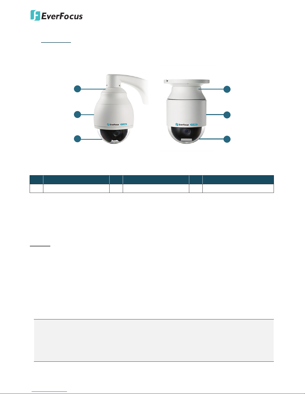
1. Overview
The EPTZ9200/9300 Series comes in two types: outdoor (EPTZ9200/9300) and indoor (EPTZ9200i/9300i).
1
2
3
1
2
3
Outdoor
(EPTZ
9200/9300
)
Indoor
(
EPTZ
9200i/
9300i
)
Item Name
No. Item Name No. Item Name No. Item Name
1 Top Housing 2 Outer Housing 3 Camera Main Body
Packing List
There are 3 boxes that are camera main body with a camera module, top housing with a base board & pin
connector and outer housing with bubble, plus one tool packet in the package. The detail accessories are
listed below:
Standard
1. Camera Main Body x 1
2. Top Housing x1
3. Outer Housing with Bubble x1
4. Tool Packet
Hexagon Wrench x1
Glove x 1 Pair
RS-485 Terminal Block
Desiccant Packs x 3
Note:
1.
Equipment configurations and supplied accessories vary by country. Please consult your local
EverFocus office or agents for more information. Please also keep the shipping carton for possible
future use.
2. Contact the shipper if any items appear to have been damaged in the shipping process.
EPTZ9200/9300 Series
2
2. Cables and I/O Terminal Block
Cable Descriptions
Power Cable
An adapter with 24 VAC~ / 3A output provides the power to the EPTZ9200/9300 Series camera. An
extension power line may be needed.
Note:
Different regions may use different ranges for AC voltage. Be sure to check the voltage range in your
area before installing.
Video Cable
A BNC cable is used for connecting an EPTZ9200/9300 Series to a DVR or a monitor. An amplifier may be
needed depending on the distance.
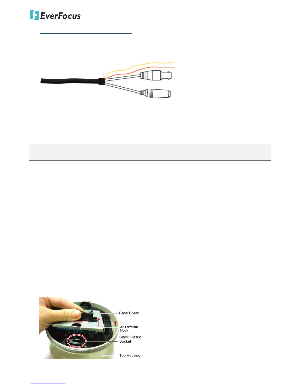
RS-485 Cable
The yellow wire carries RS-485+, and the orange wire carries RS-485-. Connect these wires to the EKB500 or
other control device in order to control the PTZ camera.
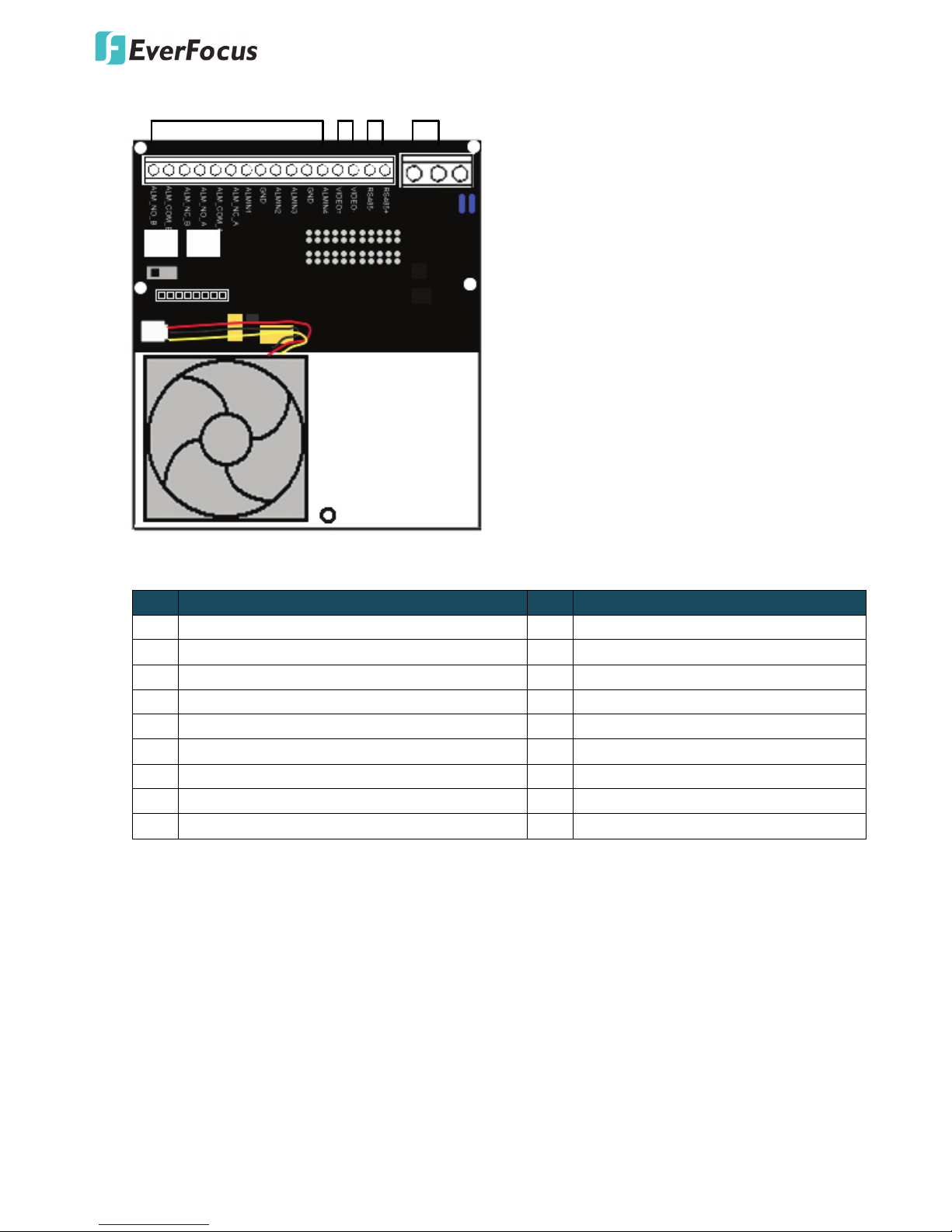
I/O Terminal Block
The base board that is inside the top housing connects to power cable, video cable, control cable, alarm
cable and fan. The housing must be removed in order to properly connect the cables. The connectors of
cable names are marked on the board in white text.
There are 4 alarm inputs and 2 alarm outputs available, represented by Pin 1~12. Pin 13 and 14 are video
pins for connecting to video cable. Pin15~16 are RS-485 pin for connecting to keyboard. Pin 17 and 18 are
power pin for connecting to 24 VAC~ p ow er.
Orange RS485
-
24VAC~
(POWER)
VIDEO
Yellow RS485+
EPTZ9200/9300 Series
3
1-12 Alarm
13-14
Video
15-16
RS485
17-18
24VAC~
EPTZ9200/9300 Series Base Board
Pin Function Pin Function
1 ALM_NO_B (Alarm Output Normal Open B) 10 ALMIN3 (Alarm Input 3)
2 ALM_COM_B (Alarm Output Common B) 11 GND (Ground)
3 ALM_NC_B (Alarm Output Normal Close B) 12 ALMIN4 (Alarm Input 4)
4 ALM_NO_A (Alarm Output Normal Open A) 13 VIDEO+
5 ALM_COM_A (Alarm Output Common A) 14 VIDEO6 ALM_NC_A (Alarm Output Normal Close A) 15 RS-4857 ALMIN1 (Alarm Input 1) 16 RS-485+
8 GND (Ground) 17 AC24A+
9 ALMIN2 (Alarm Input 2) 18 AC24B-
EPTZ9200/9300 Series
4
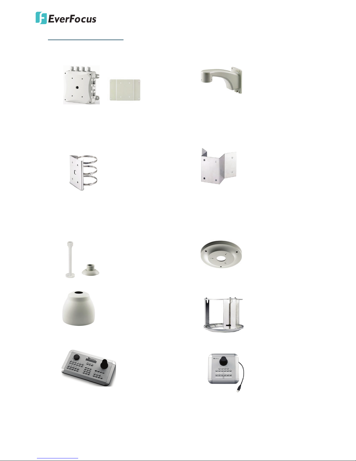
3. Optional Accessories
• EPTZ- PBOX (External power connection box)
& adaptor
• Wall mount bracket
• Pole mount adapter
(Used for installing a wall-mount bracket to a
pole, indoors or outdoors.)
• Corner mount adapter
(Used for fixing a wall-mount bracket to a
90° wall corner, indoors or outdoors.)
• Indoor ceiling pendant mount bracket &
adaptor (Used for installing a speed dome
against a ceiling.)
• Indoor concrete ceiling mount adapter
(Used for attaching a speed dome to a
concrete ceiling.)
• Outdoor sunshield
• Indoor in-ceiling mount bracket
• EKB500 (RS-485 Keyboard)
• EKB200 (USB controller keyboard)
EPTZ9200/9300 Series
5
4. Installation
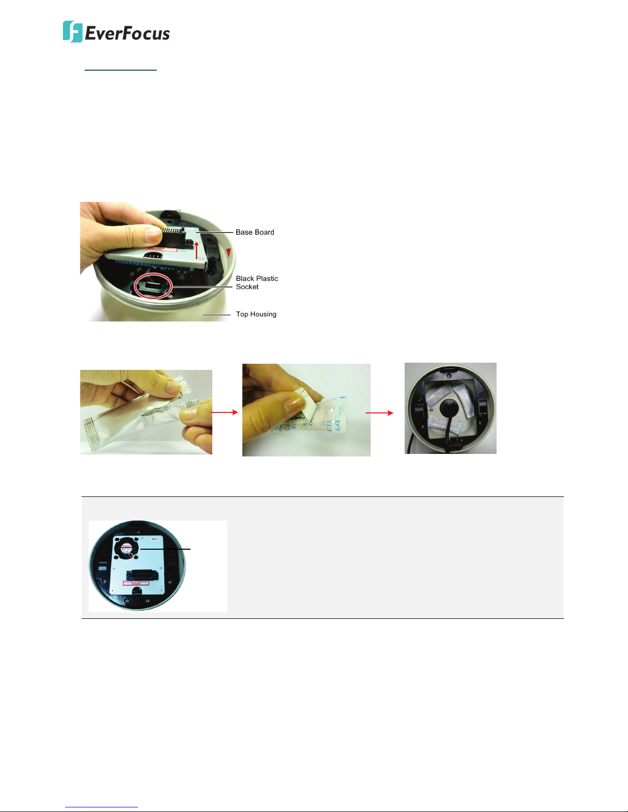
Replacing the Desiccant Bags
Before installing, replace the 3 desiccant bags inside the top housing. The desiccant bag loses its
effectiveness after you open the camera. To keep the camera’s interior dry, it is highly recommended to
replace the desiccant bags every time when you open the camera.
To replace the desiccant bags:
1. On the Top Housing, slightly press the black plastic socket backward and lift up the base board.
2. Remove the desiccant bags from the top housing.
3. Stick the supplied 3 new desiccant bags inside the top housing. Place back the base board.
Note: Ensure Not to place the desiccant bags under the position of the fan.
Fan
4. Insert the base board into the black plastic socket. The base board should click firmly into position.
Make sure the pin connector on the base board is lined up with the pin connector on the main body
when you press the two together.
 Loading...