

EverFocus EPTZ3600, EPTZ3600I User Manual
Speed Dome
EPTZ36x Series
USER MANUAL
Table of Contents
Date: Jun. 2009

2
1. EPTZ3600/EPTZ3600I OVERVIEW ......................................................... 4
1.1. Introduction ................................................................................................ 4
1.2. Specifications ............................................................................................. 5
1.3. Feature ........................................................................................................ 7
1.3.1. Profile of EPTZ3600/EPTZ3600I ........................................................... 7
1.3.2. EPTZ3600/EPTZ3600I Base Board ...................................................... 9
1.4. EPTZ3600/EPTZ3600I Quick Operation Guide (Work with EKB500) .... 10
2. EPTZ3600/EPTZ3600I INSTALLAT ION ................................................. 11
2.1. Packing List .............................................................................................. 11
2.2. Cable Needed ............................................................................................ 13
2.3. Initial Setup ............................................................................................... 13
2.3.1. Address Setting ................................................................................... 14
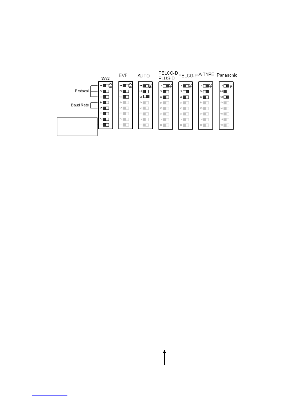
2.3.2. Communication Protocol Setting ......................................................... 18
2.3.3. Transmission Speed Setting (Baud Rate Setting) ............................... 18
2.4. Bracket and Speed Dome Installation..................................................... 18
2.4.1. Installation Requirements .................................................................... 18
2.4.2. EPTZ3600 Dome Camera Wall Mount Simple Installation .................. 19
2.4.3. EPTZ3600 Dome Camera Wall Mount Installation .............................. 22
2.4.4. EPTZ3600 Dome Camera Ceiling Mount Installation .......................... 30
2.5. Bracket & Adapter .................................................................................... 33
2.5.1. Indoor Ceiling Pendent Mount Bracket ................................................ 33
2.5.2. Pole Mount A dapter ............................................................................. 34
2.5.3. Corner Mount A dapter ......................................................................... 34
2.5.4. Indoor Concrete Ceiling Mount Adapter .............................................. 35
3. EPTZ3600/EPTZ3600I CAMERA SETUP MENU .................................. 35

3
3.1. Structure of the Setup Menu.................................................................... 35
3.2. VIDEO SETTINGS ..................................................................................... 36
3.2.1. EXPOSURE .........................................................錯誤! 尚未定義書籤。
3.2.2. FOCUS MODE .................................................................................... 38
3.2.3. DIGITAL ZOOM ................................................................................... 38
3.2.4. WHITE BALANCE ............................................................................... 39
3.2.5. BACKLIGHT ........................................................................................ 39
3.2.6. DAY/NIGHT ......................................................................................... 39
3.2.7. COLOR: .............................................................................................. 40
3.2.8. NEGATIVE .......................................................................................... 40
3.2.9. WIDE DYNAMIC RANGE .................................................................... 40
3.2.10 EXIT .................................................................................................... 41
3.3. POSITIONS ................................................................................................ 42
3.4. OSD/AREAS .............................................................................................. 45
3.4.1. CAM. TITLE......................................................................................... 45
3.4.2. AREAS ................................................................................................ 45
3.4.3. DIRECTIONS ...................................................................................... 47
3.4.4. DISPLAY ............................................................................................. 48
3.4.5. EXIT .................................................................................................... 50
3.5. AUTO MODES ........................................................................................... 50
3.5.1. AUTO TRACKING (For Auto Tracking Models Only) ........................... 50
3.5.2. AUTOPAN ........................................................................................... 56
3.5.3. PRESET TOURS................................................................................. 58
3.5.4. PATTERN ............................................................................................ 59
3.5.5. AUTO RESUME .................................................................................. 61
3.5.6. RESUME TO ....................................................................................... 61

4
3.5.7. POWER UP FUNC .............................................................................. 62
3.5.8. AUTO FLIP .......................................................................................... 62
3.5.9. EXIT .................................................................................................... 63
3.6. ALARM ...................................................................................................... 63
3.6.1. ALARM INPUTS .................................................................................. 63
3.6.2. ALARM OUTPUT S .............................................................................. 65
3.6.3. MOTION DETECT............................................................................... 66
3.6.4. EXIT .................................................................................................... 68
3.7. PRIVAT E ZONES ....................................................................................... 68
3.8. SYSTEM..................................................................................................... 71
3.9. INFO ........................................................................................................... 72
3.10. EXIT ........................................................................................................... 73
4. EPTZ3600/3600I FUNCTION SETUP AND OPERATION ..................... 74
4.1. Manual Control Mode ............................................................................... 74
4.2. Auto Tracking Mode (For Auto Tracking Models Only) ......................... 74
4.3. Auto Pan Mode ......................................................................................... 74
4.4. Position Setting ........................................................................................ 75
4.5. Tour Mode ................................................................................................. 77
4.6. Alarm Link to a Position/Tour .................................................................. 77
4.7. Other Operations ...................................................................................... 78
1. EPTZ3600/EPTZ3600I OVERVIEW
1.1. Introduction
The EPTZ3600 series uses high sensitivity and high resolution to display a high

5
quality image in m ultiple env ironments. The IR Cut Filter and Wide Dynamic functions
allows for a clear picture in all lighting conditions. The solid mount construction
prevents vibration even when moving at top speed of 360 degrees/sec. The full list of
features includes the following:
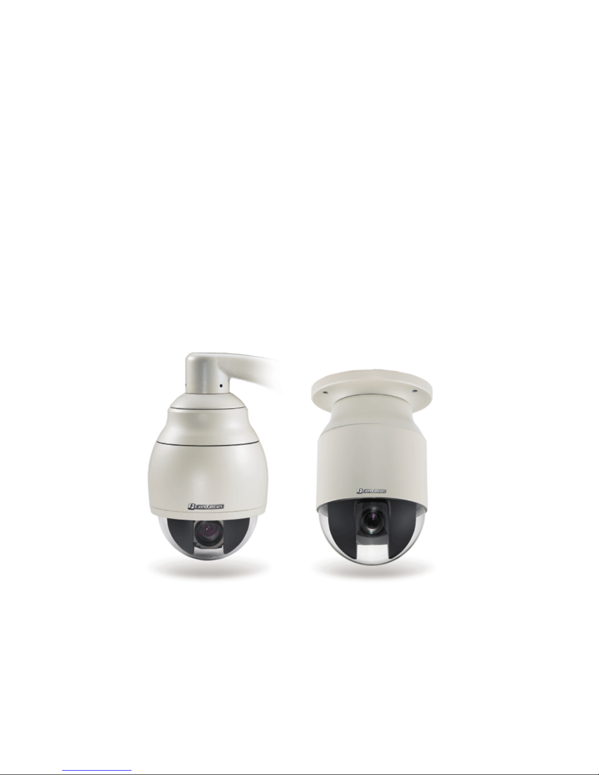
EPTZ3600 for outdoor model; EPTZ3600I for indoor model
Built in 36x Optical Zoom Lens
Super High Resolution 530TV Lines
True Day/Night function (IR Cut Filter Removable)
Wide Dynamic Range
Digital Slow Shutter
Privacy Zone Masking
Motion Detection
Auto detection of protocols
Tilt rotat ion range: 180°
192 preset positions are available
16 cruise tours can be set, and each tour contains up to 16 positions
4 Alarm Inputs / 2 Alarm Outputs
Running to position speed, 0.01º/s to 360º/s
RS485 Communication
IP66 (for EPTZ3600)
1.2. Specifications
Product Model
EPTZ3600 (outdoor)
EPTZ3600I (indoor)
Pickup Device
SONY 1/4” EX-view HAD CCD
Video Format
NTSC or PAL
Scanning System
NTSC: 525 TV lines, 60 fields/sec
PAL: 625 TV lines, 50 fields/sec.
Picture Elements
Approx. 768 x 494 (NTSC)
Approx. 752 x 582 (PAL)
Horizontal Resolution
530 TV Lines
Sensitivity
1.4 Lux/ F1.6 (Normal)
0.1 Lux/ F1.6 (ICR OFF)
0.01 Lux/ F1.6 (ICR ON)

6
S/N Ratio
50 dB (Weight ON)
Electronic Shutter
1 ~ 1/10,000(s) (NTSC)
1 ~1/10,000(s) (PAL)
Digital Slow Shutter
60x(50x for PAL)
Shutter Selection
AUTO; A.FLK; Manual (1~1/10000) selectabl e
Lens Ty pe
36x optical zoom, f=3.4 mm (wide) to 122.4mm (tele),
F1.6 to F4.5
Zoom Ratio
432x max. (36x Optical and 12x Digital zoom)
True Day & Night
Yes (Auto/DAY/NIGHT)
Backlight Comp.
Yes (OFF/ON)
Wide Dynamic Range
Yes (OFF/ON)
White Balance
Auto / Indoor / Outdoor
Motion Detection
Yes (4 zone)
Privacy Zone Masking
Yes (8 zone)
Gamma Correction
0.45
Video Output
1Vp-p / 75 ohm
Sync. Mode
Internal
Power Source
24VAC
Power Consumption
21W Max
Operating Temperature
﹣40℃~+50℃≤95
%
-10
℃~+50℃≤85%
Focus Control
One push/Auto/Manual
Horizontal Rotation Speed
0.01°/s-360°/s (1-255 grade shift gears)
Horizontal Rotation Range
360° unlimited rotation
Tilt Rotation Range
180° pendulum motion
Auto Zoom Speed Control
Control speed auto-adjusted according to zoom length
changing
Auto Pan, 2 points
scanning
Can set freely
Auto Pan Speed
1-255 grade available
Dwell Time (2 points)
1-99 second available
Preset Positions
192 positions
Running to position speed
1-255 grade available,0.01º/s - 360º/s
Dwell time at preset
1-99 available

7
position
Tour
16 groups
Tour point per group
16 preset positions
Pattern
4 patterns with 90 sec long each
Fan
Fan auto starts
Position Accuracy
±0.1°
Alarm
4 in 2 out with tour/position auto triggering
Built-in Menu for Functions
Yes
Communication
RS-485
Communication Speed
1200/2400/4800/9600bps
Built-in Protocols
EVF-1; EVF-2; Pelco-P ;Pelco-D; A-Type; Plus-D; AUTO;
Panasonic
(Plus-D supports all other brands, it is equivalent to Pelco-D)
Address Editable
Yes (through DIP switch)
Speed Dome Address
0-255
Manual Pan/Tilt Speed
Pan: 0.01º ~ 360º/s ; Tilt: 0.01º ~ 180º/s
Safety
CE, FCC
Dimensions
180mm(W) x 280mm(H) ;
7.1”(W) x 11”(H)
159mm(W) x 230mm(H)
6.3”(W) x 9.1”(H)
Weight
Approx. 3.0kg
1.3. Feature
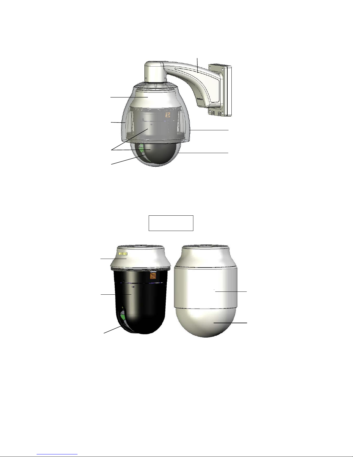
1.3.1. Profile of EPTZ3600/EPTZ3600I
EPTZ3600
8
Wall Mount Bracket
Sun shield (optional)
Bubble
Camera main body
Top housing
Camera module
Outer housing
EPTZ3600I
Bubble
Outer housing
Top housing
Camera
main body
Camera
Module
9
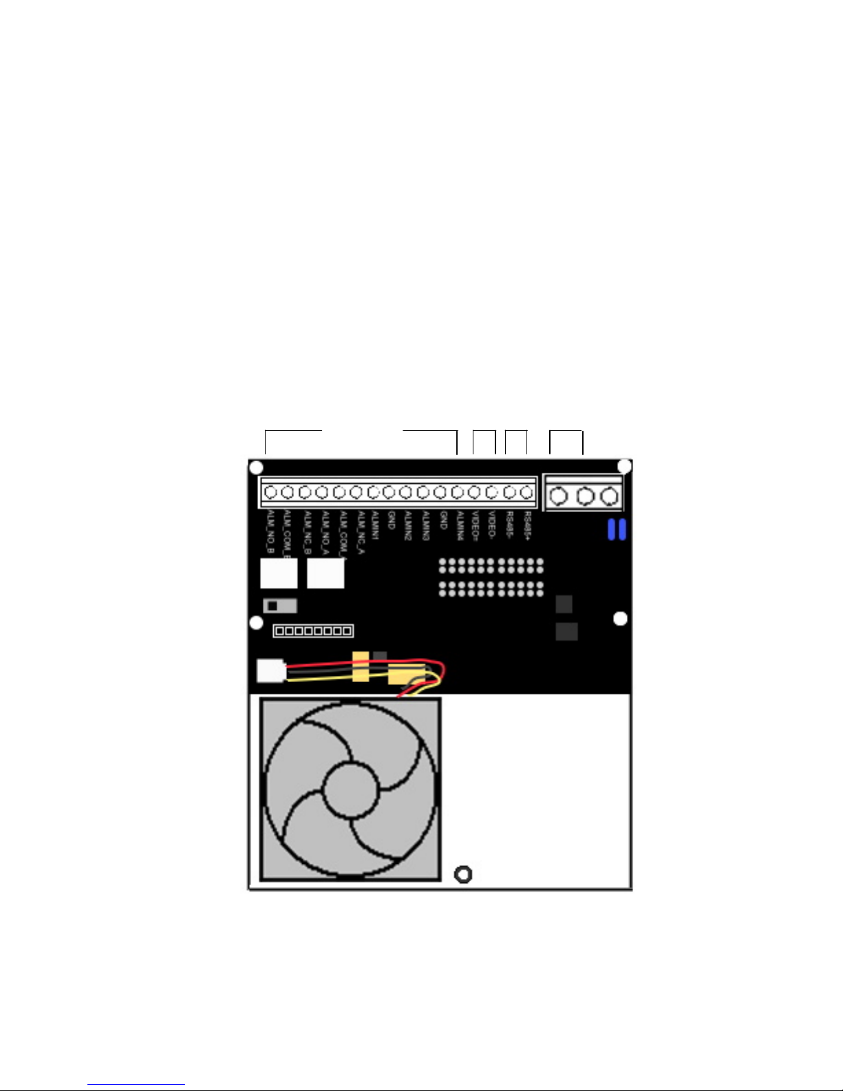
1.3.2. EPTZ3600/EPTZ3600I Base Board
The base board that is inside the top housing connects to power cable, video cable,
control cable, alarm cable and fan. The housing must be removed in order to properly
connect the cables. The connectors of c able names are marked on the board in white text.
The details of the alarm connector are shown on the APPENDIX.
There are 4 alarm inputs and 2 alarm outputs available, represented by Pin 1~12. Pin 13
and 14 are video pins for connecting to video cable. Pin15~16 are RS485 pin for
connecting to keyboard. Pin 17 and 18 are power pin for connecting to 24VAC power.
EPTZ3600 Base board
1~12 ALARM
13~14
VIDEO
15~16
RS485
17~18
24VAC

10
1.4. EPTZ3600/EPTZ3600I Quick Operation Guide (Work with EKB500)
EPTZ3600/EPTZ3600I and EKB500 (Keyboard) can work together by using factory
default setting. You just need to connect cables by the following steps:
Pin #
Function
1
ALM_NO_B (Alarm Output Normal Open B)
2
ALM_COM_B (Alarm Output Common B)
3
ALM_NC_B (Alarm Output Normal Close B)
4
ALM_NO_A (Alarm Output Normal Open A)
5
ALM_COM_A (Alarm Output Common A)
6
ALM_NC_A (Al arm Output Normal Close A)
7
ALMIN1 (Alarm Input 1)
8
GND (Ground)
9
ALMIN2 (Alarm Input 2)
10
ALMIN3 (Alarm Input 3)
11
GND (Ground)
12
ALMIN4 (Alarm Input 4)
13
VIDEO+
14
VIDEO-
15
RS485-
16
RS485+
17
AC24A+
18
AC24B-
11
1. Connect the RS-485 cable to EPTZ3600/EPTZ3600I and a keyboard (EKB500).
2. Connect a video cable from EPTZ3600/EPTZ3600I to a monitor.
3. Connect the power to the EPTZ3600/EPTZ3600I and a keyboard (EKB500).
After the EPTZ3600/EPTZ3600I finishes the self-test mode, you can start to operate
the EPTZ3600/EPTZ3600I via the keyboard.
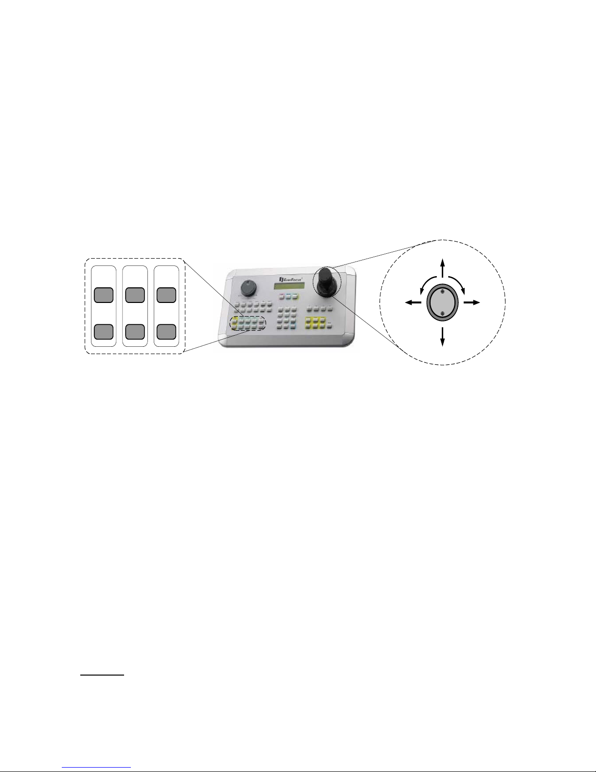
To operate the EPTZ3600/EPTZ3600I:
IRIS+FocusF.Zoom
In
- N. Out
UP
DOWN
LEFT RIGHT
Zoom INZoom OUT
1. Move the Joystick up/down or right/left to shift the camera view in that
direction.
2. Twist the top of the Joystick to zoom in/out.
3. Press the Zoom In/Out, Focus F./N., or IRIS +/- keys to manually operate
these functions.
2. EPTZ3600/EPTZ3600I INSTALLATION
2.1. Packin g Lis t
There are 3 boxes that are camera main body with a camera module, top housing with a
base board & pin connector and outer housing with bubble, plus one tool packet in the
package. The detail accessories are listed below:
Standard
Camera Main Body x 1
12
Top Housing x1
Outer Housing with Bubble x1
Tool packet
Hexagon Wrench x1
Glove x 1 pair
R S485 Term inal Block
3 desiccant packs
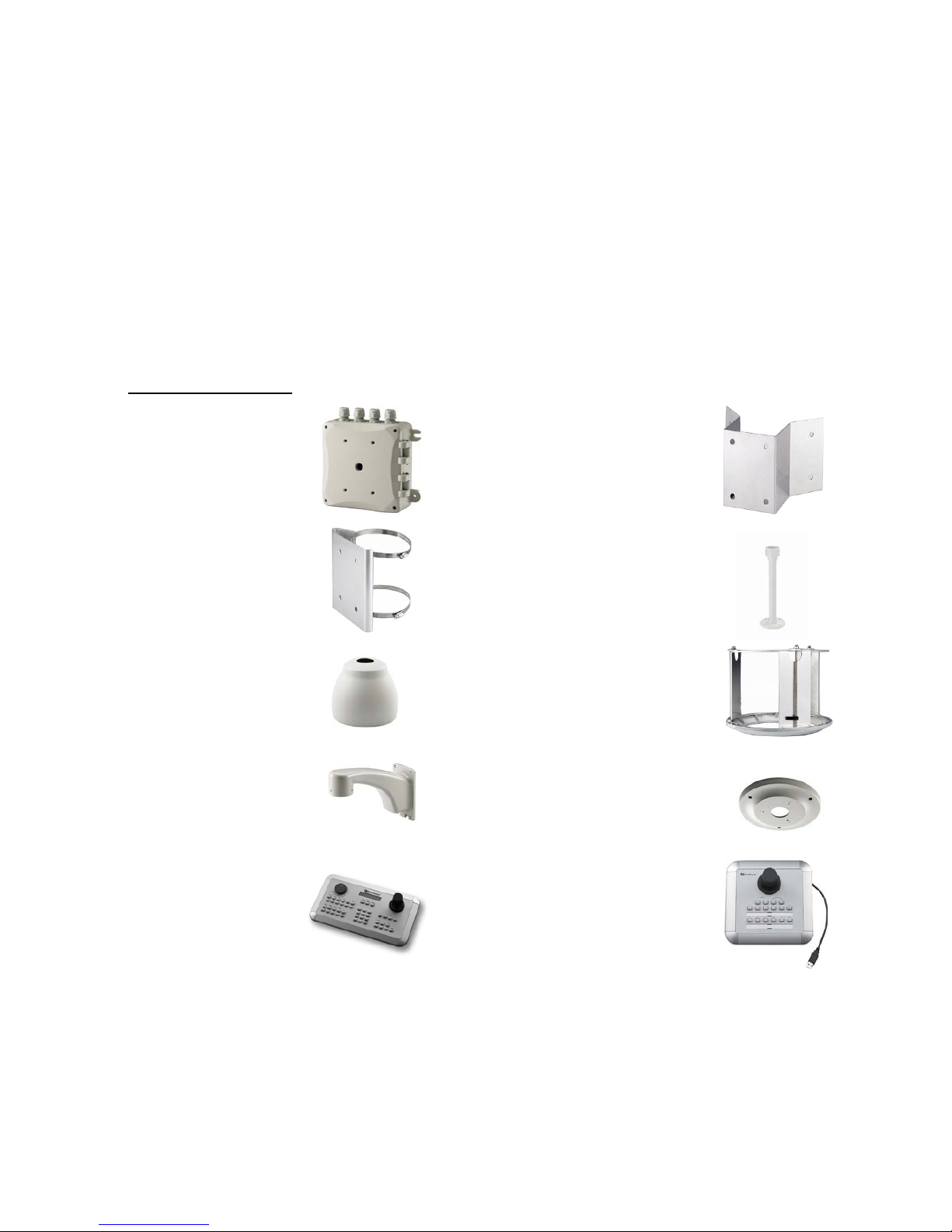
Optional Accessories
* EPTZ-PBOX
(External Power
Connection Box)
* Corner Mount Adapter
* Pole Mount Adapter
* Indoor Ceiling Pendent Mount
Bracket
* Outdoor Sunshield
* Indoor Recessed Mount Bracket
* Wall Mount Bracket
* Indoor Concrete Ceiling Mount
Adapter
* EKB500 (Keyboard) * EKB200 (USB Controller
Keyboard)
13
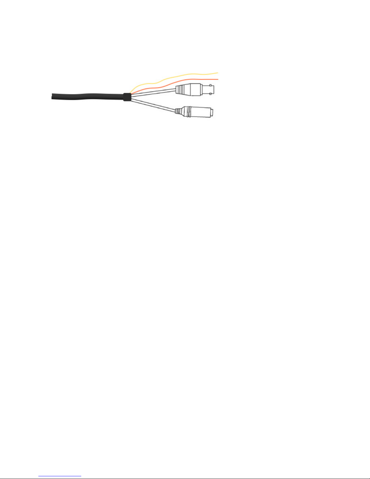
2.2. Connections
Power Cable
An adapter with 24VAC/3.5A output provides the power to the EPTZ3600/EPTZ3600I. An
extension power line may be needed.
Note: Different regions may use different ranges for AC voltage. Be sure to check the
voltage range in your area before installing.
Video Cable
A BNC cable is used for connecting an EPTZ3600/EPTZ3600I to a DVR or a monitor. An
amplifier may be needed depending on the distance.
RS485 Cable
The yellow wire carries RS485+, and the orange wire carries RS485-. Connect these
wires to the EKB500 or other control device in order to control the PTZ camera.
2.3. Initial Setup
Initial setup includes dome address, communication protocol, transmission speed, and
terminal resistance settings. All of the settings should be confirmed before the dome is
powered up. The camera's control settings must match the ones in the control device
Orange RS485-
24VAC
VIDEO
Yellow RS485+
14
(such as a keyboard or DVR).
Notice: Please make sure the power is off while making changes. EPTZ3600/EPTZ3600I
must be restarted before new values will take effect.
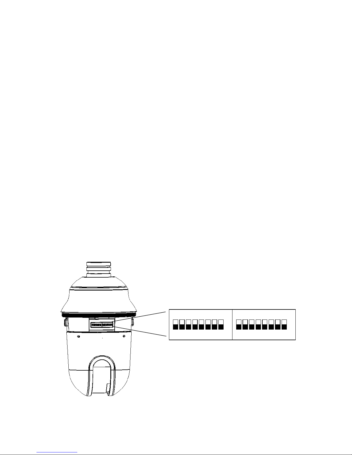
2.3.1. Address Setting
The address code of the EPTZ3600/EPTZ3600I should be set to correspond properly
with a control dev ice t o con tro l m ult iple dome cam eras. The address is ind icated by the
dip switches on the main camera body. The 8 switches correspond with the binary
code of the address, allowing up to 256 total addresses (0~255). It also means that
there are up to 256 dome cameras that can cascade on the RS-485 bus. The dip
switch setting and the indicated address are represented in the following diagram.
Note: The factory default address is 1.
ON
1 2 3 4 5 6 7 8
ON
1 2 3 4 5 6 7 8
ID address Protocol/Baud rate
15
Note: You will see the label of Protocol & Baud Rate as well as RS-485 ID address show
on the speed dome. For exam ple: for EVF protocol, w hite k eys a re a l l switched downw ard;
for ID Address 0, white keys are all switched downward.

16
ON
1 2 3 4 5 6 7 8
Switch Address
1
ON
1 2 3 4 5 6 7 8
2
ON
1 2 3 4 5 6 7 8
3
ON
1 2 3 4 5 6 7 8
4
ON
1 2 3 4 5 6 7 8
5
ON
1 2 3 4 5 6 7 8
6
ON
1 2 3 4 5 6 7 8
7
ON
1 2 3 4 5 6 7 8
8
ON
1 2 3 4 5 6 7 8
9
ON
1 2 3 4 5 6 7 8
10
ON
1 2 3 4 5 6 7 8
11
ON
1 2 3 4 5 6 7 8
12
ON
1 2 3 4 5 6 7 8
Switch Address
13
ON
1 2 3 4 5 6 7 8
14
ON
1 2 3 4 5 6 7 8
15
ON
1 2 3 4 5 6 7 8
16
ON
1 2 3 4 5 6 7 8
17
ON
1 2 3 4 5 6 7 8
18
ON
1 2 3 4 5 6 7 8
19
ON
1 2 3 4 5 6 7 8
20
ON
1 2 3 4 5 6 7 8
21
ON
1 2 3 4 5 6 7 8
22
ON
1 2 3 4 5 6 7 8
23
ON
1 2 3 4 5 6 7 8
24
ON
1 2 3 4 5 6 7 8
25
ON
1 2 3 4 5 6 7 8
26
ON
1 2 3 4 5 6 7 8
27
ON
1 2 3 4 5 6 7 8
28
ON
1 2 3 4 5 6 7 8
29
ON
1 2 3 4 5 6 7 8
30
ON
1 2 3 4 5 6 7 8
31
ON
1 2 3 4 5 6 7 8
Switch Address
33
ON
1 2 3 4 5 6 7 8
34
ON
1 2 3 4 5 6 7 8
35
ON
1 2 3 4 5 6 7 8
36
ON
1 2 3 4 5 6 7 8
37
ON
1 2 3 4 5 6 7 8
38
ON
1 2 3 4 5 6 7 8
39
ON
1 2 3 4 5 6 7 8
40
ON
1 2 3 4 5 6 7 8
41
ON
1 2 3 4 5 6 7 8
42
ON
1 2 3 4 5 6 7 8
43
ON
1 2 3 4 5 6 7 8
44
ON
1 2 3 4 5 6 7 8
45
ON
1 2 3 4 5 6 7 8
46
ON
1 2 3 4 5 6 7 8
47
ON
1 2 3 4 5 6 7 8
48
ON
1 2 3 4 5 6 7 8
49
ON
1 2 3 4 5 6 7 8
50
ON
1 2 3 4 5 6 7 8
51
ON
1 2 3 4 5 6 7 8
52
ON
1 2 3 4 5 6 7 8
53
ON
1 2 3 4 5 6 7 8
54
ON
1 2 3 4 5 6 7 8
55
ON
1 2 3 4 5 6 7 8
56
ON
1 2 3 4 5 6 7 8
57
ON
1 2 3 4 5 6 7 8
58
ON
1 2 3 4 5 6 7 8
59
ON
1 2 3 4 5 6 7 8
60
ON
1 2 3 4 5 6 7 8
61
ON
1 2 3 4 5 6 7 8
62
ON
1 2 3 4 5 6 7 8
63
Switch Address Switch AddressSwitch AddressSwitch Address Switch AddressSwitch Address
ON
1 2 3 4 5 6 7 8
Switch Address
65
ON
1 2 3 4 5 6 7 8
66
ON
1 2 3 4 5 6 7 8
67
ON
1 2 3 4 5 6 7 8
68
ON
1 2 3 4 5 6 7 8
69
ON
1 2 3 4 5 6 7 8
70
ON
1 2 3 4 5 6 7 8
71
ON
1 2 3 4 5 6 7 8
72
ON
1 2 3 4 5 6 7 8
73
ON
1 2 3 4 5 6 7 8
74
ON
1 2 3 4 5 6 7 8
75
ON
1 2 3 4 5 6 7 8
76
ON
1 2 3 4 5 6 7 8
Switch Address
77
ON
1 2 3 4 5 6 7 8
78
ON
1 2 3 4 5 6 7 8
79
ON
1 2 3 4 5 6 7 8
80
ON
1 2 3 4 5 6 7 8
81
ON
1 2 3 4 5 6 7 8
82
ON
1 2 3 4 5 6 7 8
83
ON
1 2 3 4 5 6 7 8
84
ON
1 2 3 4 5 6 7 8
85
ON
1 2 3 4 5 6 7 8
86
ON
1 2 3 4 5 6 7 8
87
ON
1 2 3 4 5 6 7 8
88
ON
1 2 3 4 5 6 7 8
89
ON
1 2 3 4 5 6 7 8
90
ON
1 2 3 4 5 6 7 8
91
ON
1 2 3 4 5 6 7 8
92
ON
1 2 3 4 5 6 7 8
93
ON
1 2 3 4 5 6 7 8
94
ON
1 2 3 4 5 6 7 8
95
ON
1 2 3 4 5 6 7 8
Switch Address
97
ON
1 2 3 4 5 6 7 8
98
ON
1 2 3 4 5 6 7 8
99
ON
1 2 3 4 5 6 7 8
100
ON
1 2 3 4 5 6 7 8
101
ON
1 2 3 4 5 6 7 8
102
ON
1 2 3 4 5 6 7 8
103
ON
1 2 3 4 5 6 7 8
104
ON
1 2 3 4 5 6 7 8
105
ON
1 2 3 4 5 6 7 8
106
ON
1 2 3 4 5 6 7 8
107
ON
1 2 3 4 5 6 7 8
108
ON
1 2 3 4 5 6 7 8
109
ON
1 2 3 4 5 6 7 8
110
ON
1 2 3 4 5 6 7 8
111
ON
1 2 3 4 5 6 7 8
112
ON
1 2 3 4 5 6 7 8
113
ON
1 2 3 4 5 6 7 8
114
ON
1 2 3 4 5 6 7 8
115
ON
1 2 3 4 5 6 7 8
116
ON
1 2 3 4 5 6 7 8
117
ON
1 2 3 4 5 6 7 8
118
ON
1 2 3 4 5 6 7 8
119
ON
1 2 3 4 5 6 7 8
120
ON
1 2 3 4 5 6 7 8
121
ON
1 2 3 4 5 6 7 8
122
ON
1 2 3 4 5 6 7 8
123
ON
1 2 3 4 5 6 7 8
124
ON
1 2 3 4 5 6 7 8
125
ON
1 2 3 4 5 6 7 8
126
ON
1 2 3 4 5 6 7 8
127
Switch Address
ON
1 2 3 4 5 6 7 8
0
ON
1 2 3 4 5 6 7 8
32
ON
1 2 3 4 5 6 7 8
64
ON
1 2 3 4 5 6 7 8
96

17
ON
1 2 3 4 5 6 7 8
Switch Address
129
ON
1 2 3 4 5 6 7 8
130
ON
1 2 3 4 5 6 7 8
131
ON
1 2 3 4 5 6 7 8
132
ON
1 2 3 4 5 6 7 8
133
ON
1 2 3 4 5 6 7 8
134
ON
1 2 3 4 5 6 7 8
135
ON
1 2 3 4 5 6 7 8
136
ON
1 2 3 4 5 6 7 8
137
ON
1 2 3 4 5 6 7 8
138
ON
1 2 3 4 5 6 7 8
139
ON
1 2 3 4 5 6 7 8
140
ON
1 2 3 4 5 6 7 8
Switch Address
141
ON
1 2 3 4 5 6 7 8
142
ON
1 2 3 4 5 6 7 8
143
ON
1 2 3 4 5 6 7 8
144
ON
1 2 3 4 5 6 7 8
145
ON
1 2 3 4 5 6 7 8
146
ON
1 2 3 4 5 6 7 8
147
ON
1 2 3 4 5 6 7 8
148
ON
1 2 3 4 5 6 7 8
149
ON
1 2 3 4 5 6 7 8
150
ON
1 2 3 4 5 6 7 8
151
ON
1 2 3 4 5 6 7 8
152
ON
1 2 3 4 5 6 7 8
153
ON
1 2 3 4 5 6 7 8
154
ON
1 2 3 4 5 6 7 8
155
ON
1 2 3 4 5 6 7 8
156
ON
1 2 3 4 5 6 7 8
157
ON
1 2 3 4 5 6 7 8
158
ON
1 2 3 4 5 6 7 8
159
ON
1 2 3 4 5 6 7 8
Switch Address
161
ON
1 2 3 4 5 6 7 8
162
ON
1 2 3 4 5 6 7 8
163
ON
1 2 3 4 5 6 7 8
164
ON
1 2 3 4 5 6 7 8
165
ON
1 2 3 4 5 6 7 8
166
ON
1 2 3 4 5 6 7 8
167
ON
1 2 3 4 5 6 7 8
168
ON
1 2 3 4 5 6 7 8
169
ON
1 2 3 4 5 6 7 8
170
ON
1 2 3 4 5 6 7 8
171
ON
1 2 3 4 5 6 7 8
172
ON
1 2 3 4 5 6 7 8
173
ON
1 2 3 4 5 6 7 8
174
ON
1 2 3 4 5 6 7 8
175
ON
1 2 3 4 5 6 7 8
176
ON
1 2 3 4 5 6 7 8
177
ON
1 2 3 4 5 6 7 8
178
ON
1 2 3 4 5 6 7 8
179
ON
1 2 3 4 5 6 7 8
180
ON
1 2 3 4 5 6 7 8
181
ON
1 2 3 4 5 6 7 8
182
ON
1 2 3 4 5 6 7 8
183
ON
1 2 3 4 5 6 7 8
184
ON
1 2 3 4 5 6 7 8
185
ON
1 2 3 4 5 6 7 8
186
ON
1 2 3 4 5 6 7 8
187
ON
1 2 3 4 5 6 7 8
188
ON
1 2 3 4 5 6 7 8
189
ON
1 2 3 4 5 6 7 8
190
ON
1 2 3 4 5 6 7 8
191
Switch Address Switch AddressSwitch AddressSwitch Address Switch AddressSwitch Address
ON
1 2 3 4 5 6 7 8
Switch Address
193
ON
1 2 3 4 5 6 7 8
194
ON
1 2 3 4 5 6 7 8
195
ON
1 2 3 4 5 6 7 8
196
ON
1 2 3 4 5 6 7 8
197
ON
1 2 3 4 5 6 7 8
198
ON
1 2 3 4 5 6 7 8
199
ON
1 2 3 4 5 6 7 8
200
ON
1 2 3 4 5 6 7 8
201
ON
1 2 3 4 5 6 7 8
202
ON
1 2 3 4 5 6 7 8
203
ON
1 2 3 4 5 6 7 8
204
ON
1 2 3 4 5 6 7 8
Switch Address
205
ON
1 2 3 4 5 6 7 8
206
ON
1 2 3 4 5 6 7 8
207
ON
1 2 3 4 5 6 7 8
208
ON
1 2 3 4 5 6 7 8
209
ON
1 2 3 4 5 6 7 8
210
ON
1 2 3 4 5 6 7 8
211
ON
1 2 3 4 5 6 7 8
212
ON
1 2 3 4 5 6 7 8
213
ON
1 2 3 4 5 6 7 8
214
ON
1 2 3 4 5 6 7 8
215
ON
1 2 3 4 5 6 7 8
216
ON
1 2 3 4 5 6 7 8
217
ON
1 2 3 4 5 6 7 8
218
ON
1 2 3 4 5 6 7 8
219
ON
1 2 3 4 5 6 7 8
220
ON
1 2 3 4 5 6 7 8
221
ON
1 2 3 4 5 6 7 8
222
ON
1 2 3 4 5 6 7 8
223
ON
1 2 3 4 5 6 7 8
Switch Address
225
ON
1 2 3 4 5 6 7 8
226
ON
1 2 3 4 5 6 7 8
227
ON
1 2 3 4 5 6 7 8
228
ON
1 2 3 4 5 6 7 8
229
ON
1 2 3 4 5 6 7 8
230
ON
1 2 3 4 5 6 7 8
231
ON
1 2 3 4 5 6 7 8
232
ON
1 2 3 4 5 6 7 8
233
ON
1 2 3 4 5 6 7 8
234
ON
1 2 3 4 5 6 7 8
235
ON
1 2 3 4 5 6 7 8
236
ON
1 2 3 4 5 6 7 8
237
ON
1 2 3 4 5 6 7 8
238
ON
1 2 3 4 5 6 7 8
239
ON
1 2 3 4 5 6 7 8
240
ON
1 2 3 4 5 6 7 8
241
ON
1 2 3 4 5 6 7 8
242
ON
1 2 3 4 5 6 7 8
243
ON
1 2 3 4 5 6 7 8
244
ON
1 2 3 4 5 6 7 8
245
ON
1 2 3 4 5 6 7 8
246
ON
1 2 3 4 5 6 7 8
247
ON
1 2 3 4 5 6 7 8
248
ON
1 2 3 4 5 6 7 8
249
ON
1 2 3 4 5 6 7 8
250
ON
1 2 3 4 5 6 7 8
251
ON
1 2 3 4 5 6 7 8
252
ON
1 2 3 4 5 6 7 8
253
ON
1 2 3 4 5 6 7 8
254
ON
1 2 3 4 5 6 7 8
255
Switch Address
ON
1 2 3 4 5 6 7 8
160
ON
1 2 3 4 5 6 7 8
192
ON
1 2 3 4 5 6 7 8
224
ON
1 2 3 4 5 6 7 8
128
18
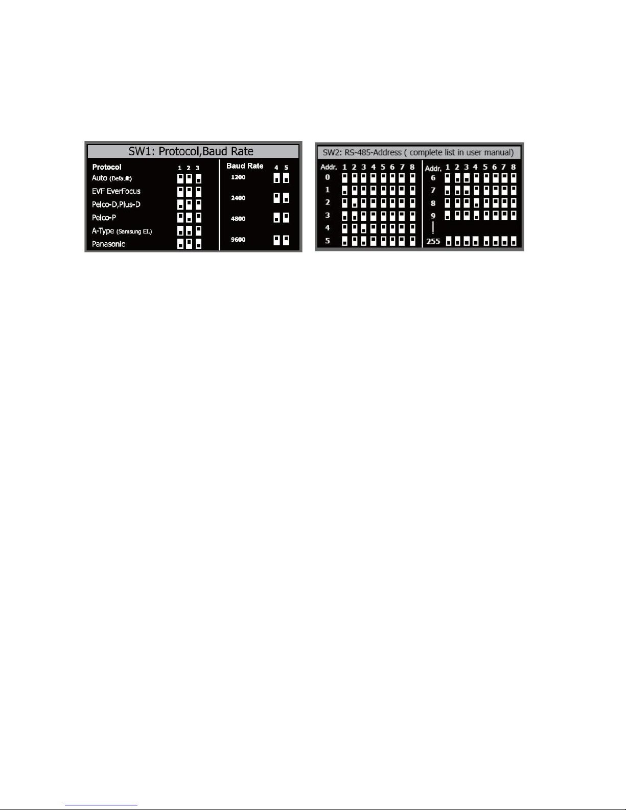
2.3.2. Communication Protocol Setting
The 1st, 2nd and 3rd bits are used to set communication protocol. The factory default
protocol is EVF.
Notice: If all protocol switches are set to ON, the EPTZ3600/EPTZ3600i will enter a
self-test mode.
2.3.3. Transmission Speed Setting (Baud Rate Setting)
The 4th and 5
th
bits on the PCB boar d ar e used to set t he Baud R ate. The defau lt baud rate
setting is 9600.
2.4. Bracket and Speed Dome Installation
2.4.1. Installation Requirements
1. Installation should be handled by a qualified service agent and should comply with
all local regulations. Service personnel should expect potential problems such as
surface strength, surfac e material, falling objec t s, outer bre aches, bu ilding v ibrat ion
or other similar conditions.
2. Check for all necessary materials, and ensure if the selected insta l lation locat ion is
suitable for the EPTZ3600/EPTZ3600I.
Bracket
19
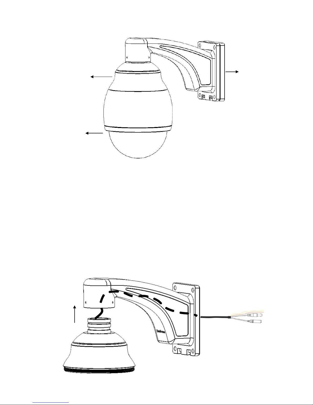
2.4.2. EPTZ3600 Dome Camera Wall Mount Simple Installation
1. Screw the top housing to bracket and secure it using the included hexagon wrench.
Bracket base
Top housing
Main body
ETPZ3600 overview

20
2. Put the waterproof silicon pad on top of the bracket base for waterproof purpose.
3. Connect the RS485, video, and power cables through the top hole of the base board. If
necessary, connect the alarm cable as well using the bottom hole.
Video cable
Power cable
RS485 cable
Alarm cable
Waterproof silicon pad
Bracket base
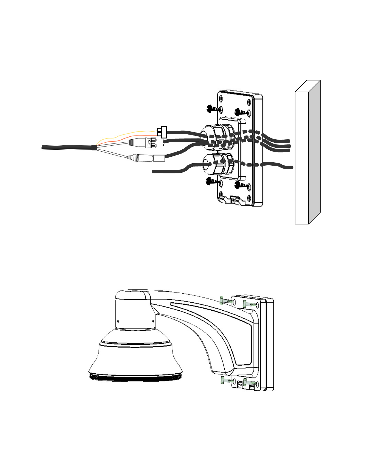
21
4. Screw in 4 screws for mounting the bracket base.
5. Screw in 4 long screws to fix the bracket to bracket base.

22
2.4.3. EPTZ3600 Dome Camera Wall Mount Installation
Note: Installations on a wall, pole, or ceiling must be able to support at least five times the
weight of the full camera assembly (about 16kg).
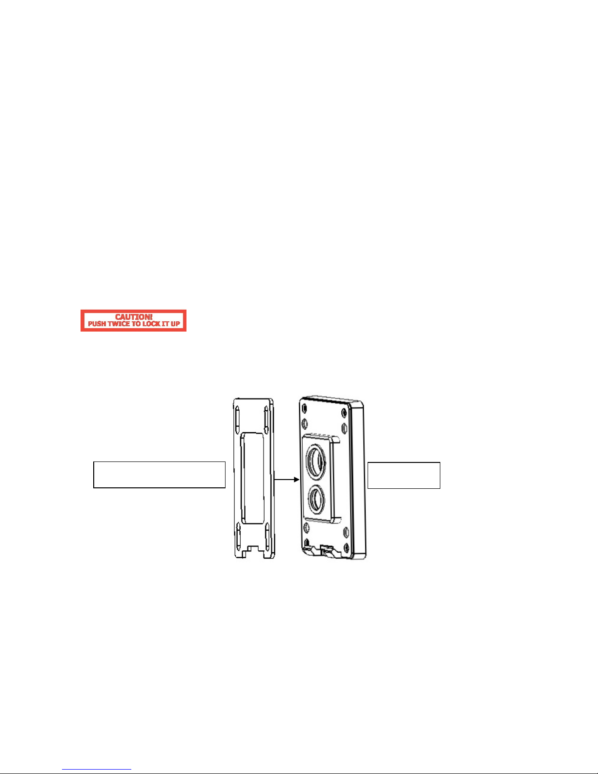
1. Pull the hole of the base board to open it. Detach the power and RS485 wires first by
using a screw driver.

23
Pull here to open
2. Apply the adhesive stripe at back of desiccant pack to the inner side of the top housing.
Three packs are included in the package.
3. When the desiccant packs are
24
Pull open this switch
pasted and the alarm and video cables are reconnected, return the base board to its
original position. You will need to pull open the switch again in order for it to fit properly.
Note:
To cl ose the base board, please push the base board twice consequently to lock it up.
4. Put the waterproof silicon pad on top of the base board for waterproof purpose.
5. Connect the RS485, video, and power cables through the top hole of the base board. If
necessary, connect the alarm cable as well using the bottom hole.
Waterproof silicon pad
Base board
 Loading...