

Page 1
EPRO NVR Series
EPRO NVR 32
EPRO NVR 16
16/32 Channels Embedded NVR with 2/4 HDDs
User’s Manual
Copyright © EverFocus Electronics Corp.
Release Date: January, 2017
Page 2

E VERFOCUS ELECTRONICS CORPORATION
EPRO NVR Series
16 / 32 Channels Embedded NVR with 2 / 4 HDDs
User’s Manual
1995-2017 EverFocus Electronics Corp.
www.everfocus.com.tw
Disclaimer
All the images including product pictures or screen shots in this document are for example only. The
images may vary depending on the product and software version. Information contained in this document
is subject to change without notice.
Copyright
All rights reserved. No part of the contents of this manual may be reproduced or transmitted in any form
or by any means without written permission of the EverFocus Electronics Corporation.
Windows is a registered trademark of the Microsoft Corporation.
Linksys is a registered trademark of the Linksys Corporation.
D-Link is a registered trademark of the D-Link Corporation.
DynDNS is a registered trademark of the DynDNS.org Corporation.
Other product and company names mentioned herein may be the trademarks of their respective owners.
Page 3

Safety Precautions
Refer all work related to the installation of this product to qualified service personnel or
system installers.
Do not block the ventilation openings or slots on the cover.
Do not drop metallic parts through slots. This could permanently damage the appliance.
Turn the power off immediately and contact qualified service personnel for service.
Do not attempt to disassemble the appliance. To prevent electric shock, do not remove
screws or covers. There are no user-serviceable parts inside. Contact qualified service
personnel for maintenance. Handle the appliance with care. Do not strike or shake, as this
may damage the appliance.
Do not expose the appliance to water or moisture, nor try to operate it in wet areas. Do
take immediate action if the appliance becomes wet. Turn the power off and refer servicing
to qualified service personnel. Moisture may damage the appliance and also may cause
electric shock.
Do not use strong or abrasive detergents when cleaning the appliance body. Use a dry cloth
to clean the appliance when it is dirty. When the dirt is hard to remove, use a mild
detergent and wipe gently.
Do not overload outlets and extension cords as this may result in a risk of fire or electric
shock.
Do not operate the appliance beyond its specified temperature, humidity or power source
ratings. Do not use the appliance in an extreme environment where high temperature or
high humidity exists. Use the NVR at temperatures within 0°C~40°C / 32°F~104°F (Storage).
The input power source is 12VDC (EPRO NVR 16); 100-240VAC~ (EPRO NVR 32).
Read Instructions
All the safety and operating instructions should be read before the unit is operated.
Retain Instructions
The safety and operating instructions should be retained for future reference.
Heed Warnings
All warnings on the unit and in the operating instructions should be adhered to.
ii
Page 4

Follow Instructions
All operating and use instructions should be followed.
Cleaning
Unplug the unit from the outlet before cleaning. Do not use liquid cleaners, abrasive or
aerosol cleaners. Use a damp cloth for cleaning.
Attachments
Do not use attachments not recommended by the product manufacturer as they may
cause hazards.
Water and Moisture
Do not use this unit near water-for example, near a bath tub, wash bowl, kitchen sink, or
laundry tub, in a wet basement, near a swimming pool, in an unprotected outdoor
installation, or any area which is classified as a wet location.
Servicing
Do not attempt to service this unit by yourself as opening or removing covers may expose
you to dangerous voltage or other hazards. Refer all servicing to qualified service
personnel.
Power Cord Protection
Power supply cords should be routed so that they are not likely to be walked on or pinched
by items placed upon or against them, playing particular attention to cords and plugs,
convenience receptacles, and the point where they exit from the appliance.
Object and Liquid Entry
Never push objects of any kind into this unit through openings as they may touch
dangerous voltage points or short-out parts that could result in a fire or electric shock.
Never spill liquid of any kind on the unit.
RTC (Real Time Clock) Battery
When encounter failure of time calibration of your DVR, the issue may be caused by
running-out of RTC battery. Users will have to change the RTC battery on the main board
of the NVR.
ATTENTION! This is a class A product which may cause radio interference in a domestic
environment; in this case, the user may be urged to take adequate measures.
iii
Page 5

Federal Communication Commission Interference Statement
This equipment has been tested and found to comply with the limits for a Class B digital
device, pursuant to Part 15 of the FCC Rules. These limits are designed to provide
reasonable protection against harmful interference in a residential installation. This
equipment generates, uses and can radiate radio frequency energy and, if not installed
and used in accordance with the instructions, may cause harmful interference to radio
communications. However, there is no guarantee that interference will not occur in a
particular installation. If this equipment does cause harmful interference to radio or
television reception, which can be determined by turning the equipment off and on, the
user is encouraged to try to correct the interference by one of the following measures:
•Reorient or relocate the receiving antenna.
•Increase the separation between the equipment and receiver.
•Connect the equipment into an outlet on a circuit different from that to which the
receiver is connected.
•Consult the dealer or an experienced radio/TV technician for help.
FCC Caution: Any changes or modifications not expressly approved by the party
responsible for compliance could void the users’ authority to operate this equipment.
WEEE
The information in this manual was current upon publication. The manufacturer reserves the right to
revise and improve his products. Therefore, all specifications are subject to change without prior
notice. Manufacturer is not responsible for misprints or typographical errors.
Please read this manual carefully before installing and using this unit. Be sure to keep it handy for
later reference.
This Product is RoHS compliant.
Your EverFocus product is designed and manufactured with high quality materials and
components which can be recycled and reused. This symbol means that electrical and
electronic equipment, at their end-of-life, should be disposed of separately from your
household waste. Please, dispose of this equipment at your local community waste
collection/recycling centre. In the European Union there are separate collection systems
for used electrical and electronic product.
Please, help us to conserve the environment we live in!
iv
Page 6

TABLE OF CONTENTS
1. Introduction ................................................................................................................... 1
1.1 Features .......................................................................................................................... 1
1.2 Packing List ...................................................................................................................... 2
1.3 Dimensions ...................................................................................................................... 2
1.4 Front Panel ...................................................................................................................... 3
1.5 Rear Panel ....................................................................................................................... 4
2. Connection and Installation............................................................................................ 6
2.1 Hard Disk Installation ...................................................................................................... 6
2.1.1 Hard Disk Compatibility List ........................................................................................ 9
2.2 Basic Connection ........................................................................................................... 10
2.2.1 Alarm I/O ................................................................................................................... 12
2.3 Accessing the Web Interface of NVR ............................................................................ 13
3. Getting Started ............................................................................................................ 17
3.1 Turning On / Off the Power .......................................................................................... 17
3.2 Restart the NVR............................................................................................................. 18
3.3 Startup Wizard .............................................................................................................. 19
3.4 Live View Window ......................................................................................................... 23
3.5 Live Channel Tool Bar .................................................................................................... 24
3.5.1 Digital Zoom .............................................................................................................. 25
3.5.2 PTZ Control ................................................................................................................ 26
4. OSD Root Menu ........................................................................................................... 28
4.1 Main Menu .................................................................................................................... 30
4.1.1 Settings ...................................................................................................................... 30
4.1.1.1 Display .............................................................................................................. 30
4.1.1.1.1 IP Channels ........................................................................................ 30
4.1.1.1.2 Live ..................................................................................................... 34
4.1.1.1.3 Output ............................................................................................... 35
4.1.1.1.4 Privacy Mask ...................................................................................... 36
4.1.1.2 Record .............................................................................................................. 37
4.1.1.2.1 Record ................................................................................................ 37
4.1.1.2.2 Record Schedule ................................................................................ 38
v
Page 7

4.1.1.2.3 Main Stream ...................................................................................... 39
4.1.1.2.4 Sub Stream ........................................................................................ 40
4.1.1.2.5 Mobile Stream ................................................................................... 41
4.1.1.3 Network ............................................................................................................ 42
4.1.1.3.1 Network ............................................................................................. 42
4.1.1.3.2 Email .................................................................................................. 43
4.1.1.3.3 Email Schedule................................................................................... 44
4.1.1.3.4 DDNS .................................................................................................. 45
4.1.1.3.5 RTSP ................................................................................................... 46
4.1.1.4 Alarm ................................................................................................................ 47
4.1.1.4.1 Motion ............................................................................................... 47
4.1.1.4.2 Alarm ................................................................................................. 48
4.1.2 Record Search ........................................................................................................... 50
4.1.2.1 General ............................................................................................................. 50
4.1.2.1.1 Playback Mode .................................................................................. 51
4.1.2.2 Events ............................................................................................................... 53
4.1.2.2.1 Backup ............................................................................................... 55
4.1.3 Device ........................................................................................................................ 56
4.1.3.1 HDD................................................................................................................... 56
4.1.3.2 PTZ .................................................................................................................... 57
4.1.4 System ....................................................................................................................... 59
4.1.4.1 General ............................................................................................................. 59
4.1.4.1.1 General .............................................................................................. 59
4.1.4.1.2 DST ..................................................................................................... 60
4.1.4.1.3 NTP .................................................................................................... 61
4.1.4.2 Users ................................................................................................................. 62
4.1.4.3 Info ................................................................................................................... 64
4.1.4.3.1 Info ..................................................................................................... 64
4.1.4.3.2 Channel Info ...................................................................................... 64
4.1.4.3.3 Record Info ........................................................................................ 65
4.1.4.4 Log .................................................................................................................... 65
4.1.5 Advanced .................................................................................................................. 66
4.1.5.1 Maintain ........................................................................................................... 66
4.1.5.2 Events ............................................................................................................... 67
4.1.6 Shutdown .................................................................................................................. 68
4.2 Lock/Unlock Screen ....................................................................................................... 68
5. Remote Access to the NVR ........................................................................................... 69
5.1 Accessing the NVR on the Network .............................................................................. 69
5.2 Remote Live View Window ........................................................................................... 72
vi
Page 8

5.2.1 Camera List ................................................................................................................ 73
5.2.2 Live View Function Icons ........................................................................................... 74
5.2.3 PTZ Control Panel ...................................................................................................... 76
5.2.4 Image Control............................................................................................................ 78
5.3 Playback ........................................................................................................................ 79
5.3.1 Download .................................................................................................................. 82
5.4 Remote Setting ............................................................................................................. 83
5.4.1 Display ....................................................................................................................... 83
5.4.1.1 IP Camera ......................................................................................................... 83
5.4.1.2 Live.................................................................................................................... 85
5.4.1.3 Privacy Zone ..................................................................................................... 85
5.4.2 Record ....................................................................................................................... 86
5.4.2.1 Rec Parameters ................................................................................................ 86
5.4.2.2 Schedule ........................................................................................................... 87
5.4.2.3 Main Stream ..................................................................................................... 88
5.4.2.4 Sub Stream ....................................................................................................... 88
5.4.2.5 Mobile Stream .................................................................................................. 89
5.4.3 Capture ...................................................................................................................... 90
5.4.3.1 Capture ............................................................................................................. 90
5.4.3.2 Capture Schedule ............................................................................................. 91
5.4.4 Network .................................................................................................................... 92
5.4.4.1 Network ............................................................................................................ 92
5.4.4.2 Email ................................................................................................................. 93
5.4.4.2.1 Email Schedule................................................................................... 93
5.4.4.3 DDNS ................................................................................................................. 94
5.4.4.4 RTSP .................................................................................................................. 95
5.4.5 Alarm ......................................................................................................................... 96
5.4.5.1 Motion .............................................................................................................. 97
5.4.5.2 Alarm ................................................................................................................ 98
5.4.6 Device ...................................................................................................................... 101
5.4.6.1 Local Settings .................................................................................................. 101
5.4.6.2 HDD................................................................................................................. 102
5.4.6.3 PTZ .................................................................................................................. 103
5.4.7 System ..................................................................................................................... 104
5.4.7.1 General ........................................................................................................... 104
5.4.7.2 Users ............................................................................................................... 106
5.4.7.3 Info ................................................................................................................. 108
5.4.7.4 Channel Info ................................................................................................... 108
5.4.7.5 Record Info ..................................................................................................... 108
5.4.8 Advanced ................................................................................................................ 109
vii
Page 9

5.4.8.1 Firmware Upgrade .......................................................................................... 109
5.4.8.2 Load Default ................................................................................................... 109
5.4.8.3 Event Settings ................................................................................................. 110
5.4.8.4 System Maintenance ...................................................................................... 111
6. Specification .............................................................................................................. 112
7. Troubleshooting ......................................................................................................... 114
8. Usage Maintenance ................................................................................................... 116
Appendix A: IR Remote Control ......................................................................................... 117
Appendix B: Recording Backup through EF-Reader ............................................................. 118
viii
Page 10

EPRO NVR Series
1
Chapter
1. Introduction
EverFocus’ EPRO NVR Series is a professional embedded network video recorder designed for
small and medium-sized businesses (SMB) and enterprises. Operating on a Linux-based system,
the NVR offers quick PC-less configuration, network-based surveillance connection, megapixel
recording as well as playback, up to 32 channels and 24TB storage capacities are supported.
The NVR supports multi-channel playback at multiple speed options and easy data search by event
date and time. Users may enable and perform the specified functions through the local OSD menu
or Web interface. Furthermore, you can use EverFocus Mobile Applications, MobileFocus, to
remotely view the camera streams from the NVR through your handheld devices; or use EverFocus
Genie XMS central management system for remote management. You can also use EverFocus EFReader to back up recordings from the NVRs.
EverFocus’ EPRO NVR Series is the best choice for a complete network-based surveillance solution.
It is versatile, flexible and well catered to the needs of the industry.
Model Name Max. CH Enternal HDD (3.5“ SATA HDD) Ethernet Alarm In/Out
EPRO NVR 32 32Ch 4 x HDD (up to 6TB each) 2 x RJ-45 16 / 4
EPRO NVR 16 16Ch 2 x HDD (up to 6TB each) 1 x RJ-45 16 / 1
1.1 Features
• Records up to 32CH – EPRO NVR 32 (main stream and sub stream)
• Records up to 16CH – EPRO NVR 16 (main stream and sub stream)
• Supports ONVIF IP cameras
• Supports H.265 and H.264 codec
• Supports dual-stream recording
• Supports 4HDD (up to 6TB each)
• Multiple serial interfaces
• Supports mobile applications (MobileFocus)
• Multiple network monitoring: Web viewer, Genie XMS CMS
• Certificates: CE, FCC, UL, RoHS
1
Page 11
EPRO NVR Series
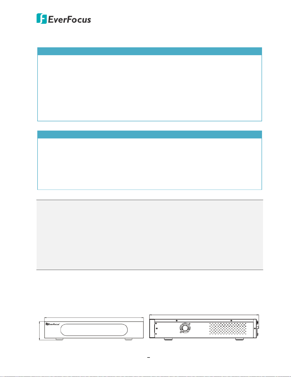
430mm / 16.93"
79.5mm / 3.13"
399.3mm / 15.72"
1.2 Packing List
EPRO NVR 32
• NVR x 1
• Mouse x 1
• Power Cord x 1
• HDD Bracket x 4
• Rack Ear x 2
• IR Remote Control x 1 (with two AAA batteries. See Note 4)
• Screws Pack x 1 (Sliver Screw x 16, Washer Head Screw x 8, M3 (φ6.8) Screw x 4)
• CD x 1 (see Note 3)
• Quick Installation Guide x 1
EPRO NVR 16
• NVR x 1
• Mouse x 1
• Power Adaptor x 1
• IR Remote Control x 1 (with two AAA batteries. See Note 4)
• HDD Screws Pack x 1
• CD x 1 (see Note 3)
• Quick Installation Guide x 1
Note:
1. Equipment configurations and supplied accessories vary by country. Please consult your
local EverFocus office or agents for more information. Please also keep the shipping carton
for possible future use.
2. Contact the shipper if any items appear to have been damaged in the shipping process.
3. The CD contains the IP Utility software, User Manual and Quick Installation Guide.
4. Risk of explosion if battery is replaced by an incorrect type. Dispose of used batteries
according to the instructions.
a. Use only two AAA dry cell batteries.
b. Do not dispose of the batteries in a fire as it may explode.
1.3 Dimensions
EPRO NVR 32
2
Page 12
EPRO NVR Series
EPRO NVR 32
1
3
2
EPRO NVR 16
2 31
EPRO NVR 16
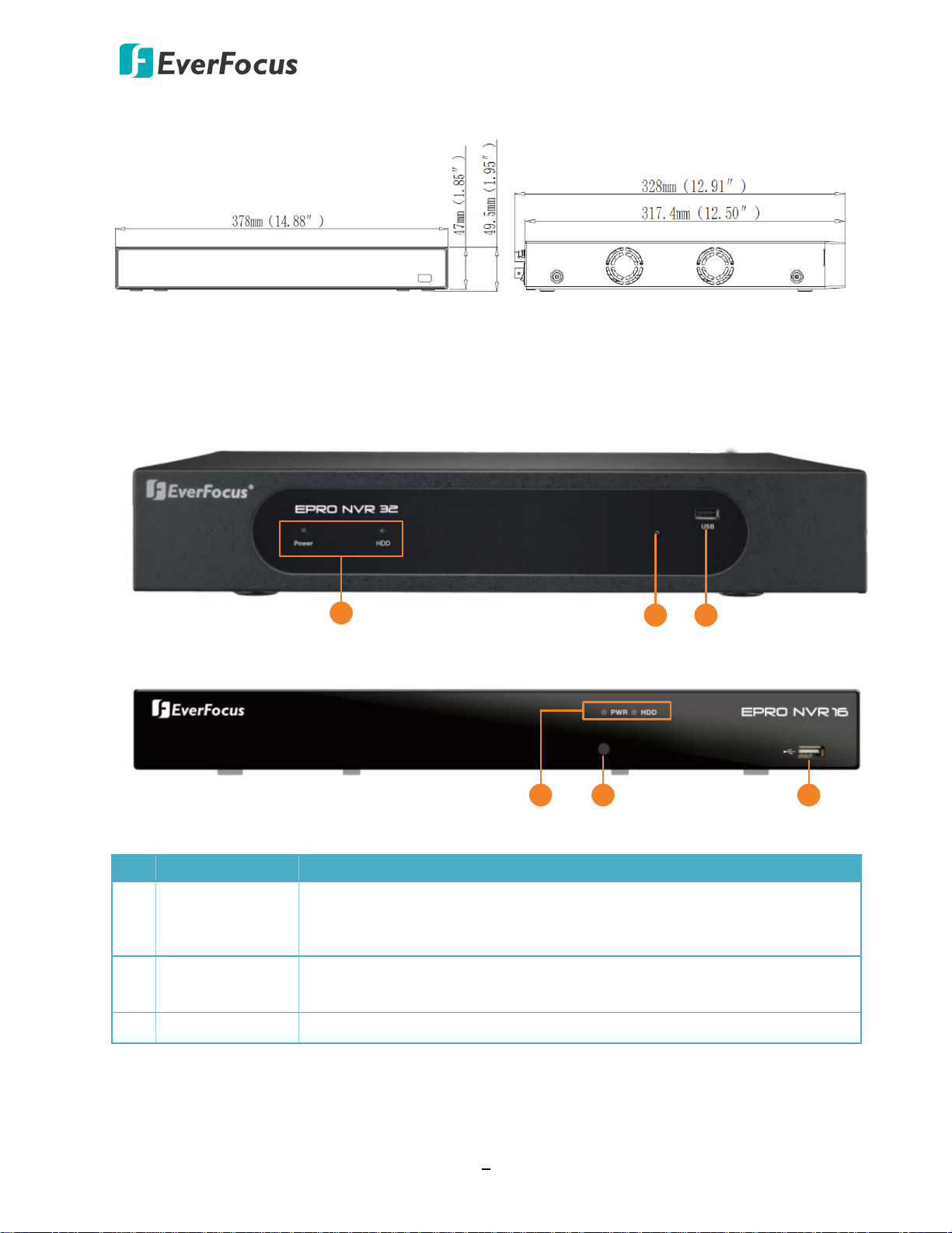
1.4 Front Panel
No. Name Description
1 LED Indicator
2 IR Receiver
3 USB Port USB2.0 port for connecting to a mouse or an external storage device.
Power: When power is on, the LED will continue lighting in green.
HDD: When power is on, the LED will continue lighting in red. When
HDD is reading/writing data, the LED will flashes red.
Receiver for signals from the IR remote control. Please refer to
Appendix A. IR Remote Control.
3
Page 13
EPRO NVR Series
EPRO NVR 32
3 4
5
6
IN 1 2 3 4 5 6 7 8 9 10 11 12 NO4COM4 G G
G G + -
KB RS485
+ - NO1COM1 NO2 COM2NO3 COM3
OUT OUT
13 14 15 16
ALARM
7
1
2
8
9
10
11
12
13
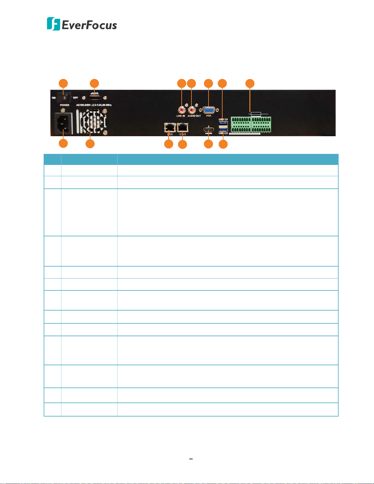
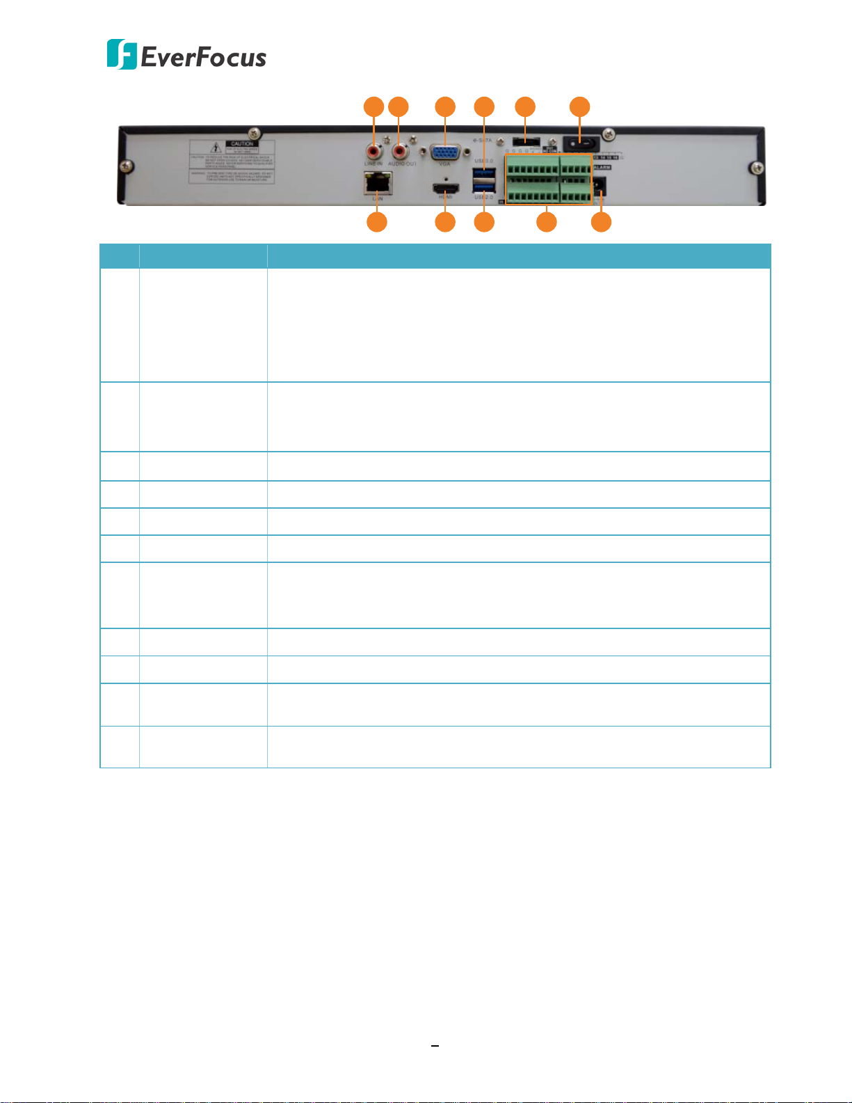
1.5 Rear Panel
No. Name Description
1 Power Switch Press to turn On / Off the NVR.
2 eSATA Port Connects to an external eSATA storage device.
Connects to a line-in audio input devices, such as microphones. Note
that the microphone with a (built-in) amplifier and external power
3 Audio Input
supply are required. The microphone audio source can be output to the
speakers on the client PC through NVR Web browser (The function is
currently reserved).
4 Audio Output
5 VGA Port Connects to a monitor using a VGA cable.
6 USB3.0 Port USB3.0 port for connecting to a mouse or an external storage device.
7 Alarm I/O
8 Power Port Connects to the power using the supplied Power Cord.
9 Fan Internal fan.
10 LAN
11 WAN
12 HDMI Port Connects to a monitor using a HDMI cable.
13 USB2.0 Port USB2.0 port for connecting to a mouse or an external storage device.
Connects to the audio output devices, such as speakers. Note that the
speaker with a (built-in) amplifier and external power supply are
required. The audio source from the cameras can be output here.
Connects up to 16 alarm input and 4 alarm output, and RS-485 devices.
Please refer to 2.2.1 Alarm I/O for more details.
Connects to a router or switch for connecting IP cameras using a
standard RJ-45 CAT5 10/100/1000Mb Ethernet cable. Please refer to
2.3 Basic Connection.
Connects to the network using a standard RJ-45 CAT5 10/100/1000Mb
Ethernet cable.
4
Page 14
EPRO NVR Series
EPRO NVR 16
7
1 2
3 5 64
8 9 10
11
No. Name Description
Connects to a line-in audio input devices, such as microphones. Note
that the microphone with a (built-in) amplifier and external power
1 Audio Input
supply are required. The microphone audio source can be output to the
speakers on the client PC through NVR Web browser (The function is
currently reserved).
Connects to the audio output devices, such as speakers. Note that the
2 Audio Output
speaker with a (built-in) amplifier and external power supply are
required. The audio source from the cameras can be output here.
3 VGA Port Connects to a monitor using a VGA cable.
4 USB3.0 Port USB3.0 port for connecting to a mouse or an external storage device.
5 eSATA Port Connects to an external eSATA storage device.
6 Power Switch Press to turn On / Off the NVR.
Connects to a router or switch for connecting IP cameras using a
7 LAN
standard RJ-45 CAT5 10/100/1000Mb Ethernet cable. Please refer to
2.3 Basic Connection.
8 HDMI Port Connects to a monitor using a HDMI cable.
9 USB2.0 Port USB2.0 port for connecting to a mouse or an external storage device.
10 Alarm I/O
11 Power Port
Connects up to 16 alarm input and 1 alarm output, and RS-485 devices.
Please refer to 2.2.1 Alarm I/O for more details.
Connects to the power using the supplied Power Adaptor and Power
Cord.
5
Page 15
EPRO NVR Series
Silver Screw
HDD Bracket
2
Chapter
2. Connection and Installation
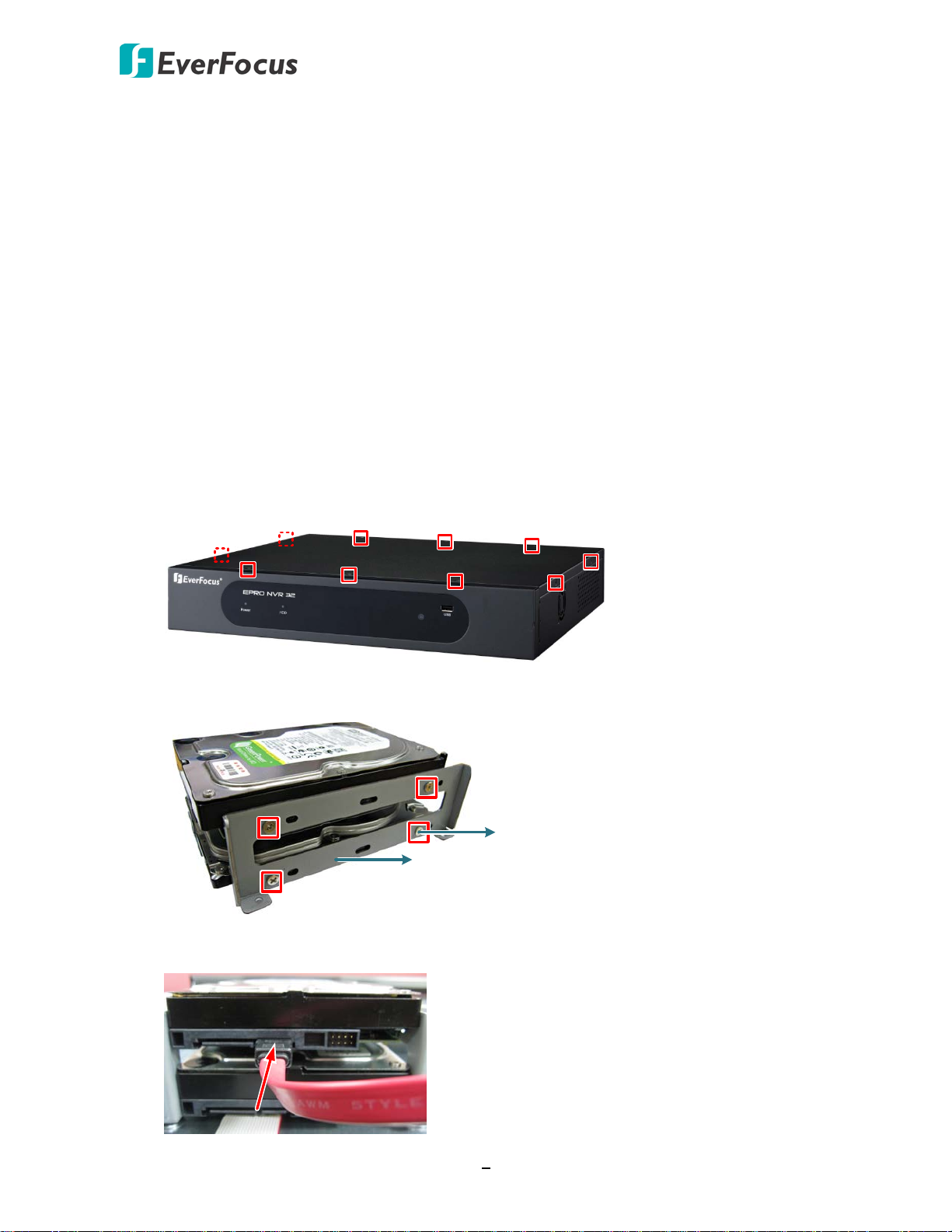
2.1 Hard Disk Installation
EPRO NVR 32
You can install up to four 3.5” HDDs inside the NVR for recording videos. The maximum capacity
of each HDD is up to 6TB.
1. Make sure the NVR is power-off.
2. Unscrew the ten housing screws on the NVR, and remove the housing from the NVR.
3. Screw two HDD brackets on both sides of the HDDs using the Sliver Screws.
4. Find the SATA cable inside the NVR, and connect the SATA cable to the SATA port on the
HDD.
6
Page 16
EPRO NVR Series
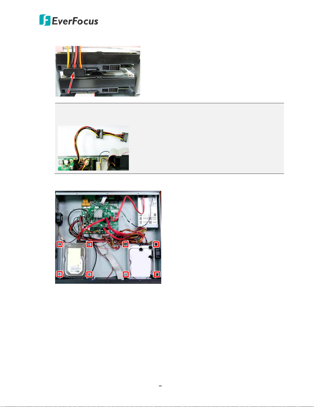
5. Find the internal power cable, and connect the internal power cable to the HDD.
Note: The internal power cable is connected to the Main board inside the NVR. The
power cable features multiple connectors, which can be used to connect up to four
HDDs.
6. Screw the HDD brackets inside the NVR using the Washer Head Screws.
7. Screw the housing back to the NVR.
7
Page 17
EPRO NVR Series
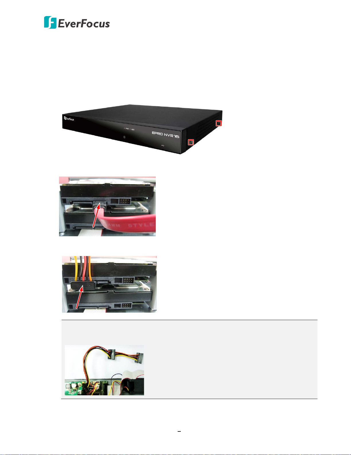
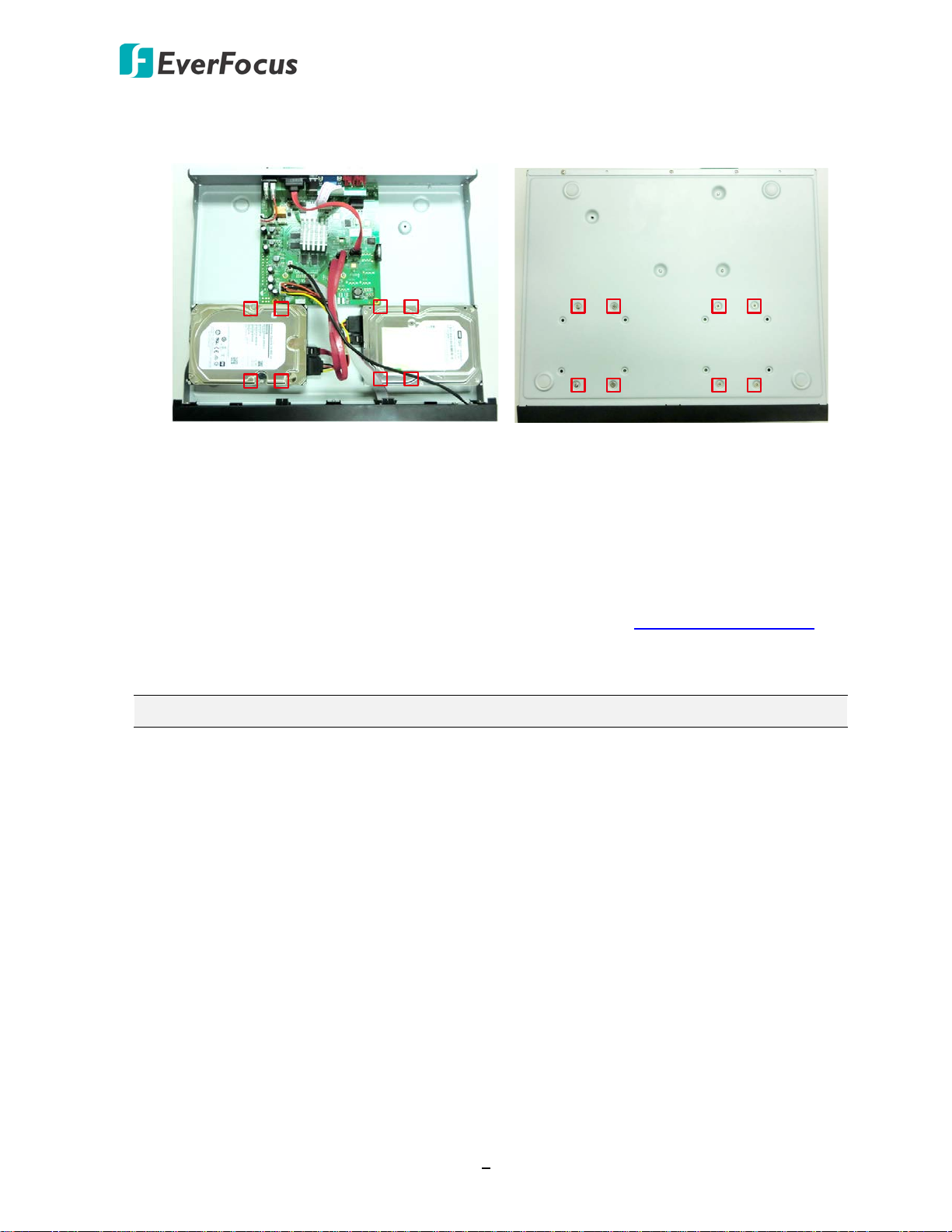
EPRO NVR 16
You can install up to two 3.5” HDDs inside the NVR for recording videos. The max. capacity of
each HDD is up to 6TB.
1. Make sure the NVR is power-off.
2. Unscrew the 8 housing screws on the NVR (2 on both sides and 4 on the rear side), and
remove the housing from the NVR.
3. Find the SATA cable inside the NVR, and connect the SATA cable to the SATA port on the
HDD.
4. Find the internal power cable, and connect the internal power cable to the HDD.
Note: The internal power cable is connected to the Main board inside the NVR. The
power cable features multiple connectors, which can be used to connect up to two
HDDs.
8
Page 18
EPRO NVR Series
5. Screw the HDDs to the bottom of the NVR using the supplied screws (inside HDD Screws
Pack). Note the screws should be inserted from the outside of the bottom case.
6. Screw the housing back to the NVR.
2.1.1 Hard Disk Compatibility List
Please go to the product page (Download) on EverFocus’ Website www.everfocus.com.tw to
see the latest Hard Disk Compatibility List. It’s recommended to use the hard disk models listed
in the Hard Disk Compatibility List to ensure your hard disks will be compatible.
Note: If using two or more hard disks, please choose the hard disks with the same capacity.
9
Page 19
EPRO NVR Series
IN 1 2 3 4 5 6 7 8 9 10 11 12 NO4COM4 G G
G G + -
KB RS485
+ - NO1COM1 NO2 COM2NO3 COM3
OUT OUT
13 14 15 16
ALARM
Mouse
5
EPRO NVR 32
Power
supply
6
IP Camera
Web Remote Client
Genie XMS CMS
Network
Line Level
Audio In / Out
2
3
Monitor
(HDMI / VGA)
4
3
3.5" HDD
1
EPRO NVR 16
Mouse
3.5" HDD
1
5
Monitor
(HDMI / VGA)
4
Power
supply
6
Line Level
Audio In / Out
2
3
Web Remote Client
IP Camera
Genie XMS CMS
Network
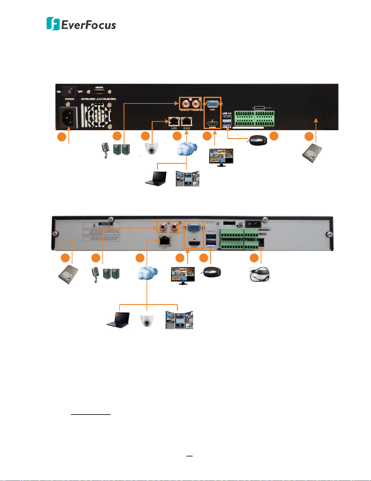
2.2 Basic Connection
The instructions below describe the basic connection to the NVRs.
1. To record videos, install the 3.5” HDD(s) to the NVR. Please refer to 2.1 Hard Disk Installation.
2. To listen to the audio from device side, connect a speaker to the audio output. To transmit
audio from the NVR to the Web client side (the function is currently reserved), connect
microphones to the audio input. Note that the microphones and speakers with a (built-in)
amplifier and external power supply are required.
3. Connect the IP cameras to the NVR and connect the NVR to the network.
EPRO NVR 32: Connects to a router or switch to the LAN port for connecting IP cameras
using a standard RJ-45 CAT5 10/100/1000Mb Ethernet cable. Connects the NVR to the
network through the WAN port using a standard RJ-45 CAT5 10/100/1000Mb Ethernet
cable.
10
Page 20

EPRO NVR Series
EPRO NVR 16: Use a standard RJ-45 CAT5 Ethernet cable to connect the LAN port of the
NVR to the network.
4. To view videos at local site, connect a monitor to the HDMI or VGA port using the HDMI or
VGA cable supplied by the monitor manufacturer.
5. Optionally connect a mouse to the NVR to control the system. You can also control the
system using the supplied IR Remote Control (Appendix A. IR Remote Control).
6. Use the supplied Power Cord (EPRO NVR 32) / Power Adaptor (EPRO NVR 16) to connect the
NVR to the power outlet.
11
Page 21
EPRO NVR Series
G G
RS-485
+ -
Alarm Output
13 14 15 16
Alarm Input
G G
Alarm Input
1 2 3 4 5 6 7 8 9 10 11 12
KB
+ -
NO1
COM1
Alarm Output
NO2
COM2
NO3
COM3
Alarm Output
NO4
COM4
G G G G
RS-485
+ -
Alarm Output
NO COM
13 14 15 16 G
Alarm Input
G
Alarm Input
1 2 3 4 5 6 7 8 9 10 11 12
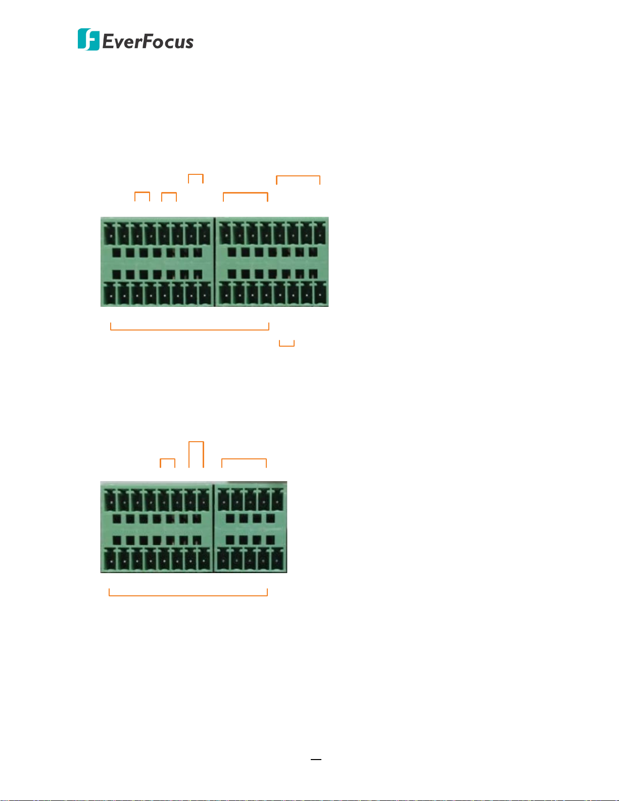
2.2.1 Alarm I/O
The NVR provides alarm I/O and RS-485 connections. Please refer to the image below for PIN
assignment.
EPRO NVR 32 provides 16 alarm inputs, 4 alarm outputs and 1 RS-485.
EPRO NVR 16 provides 16 alarm inputs, 1 alarm output and 1 RS-485.
12
Page 22
EPRO NVR Series
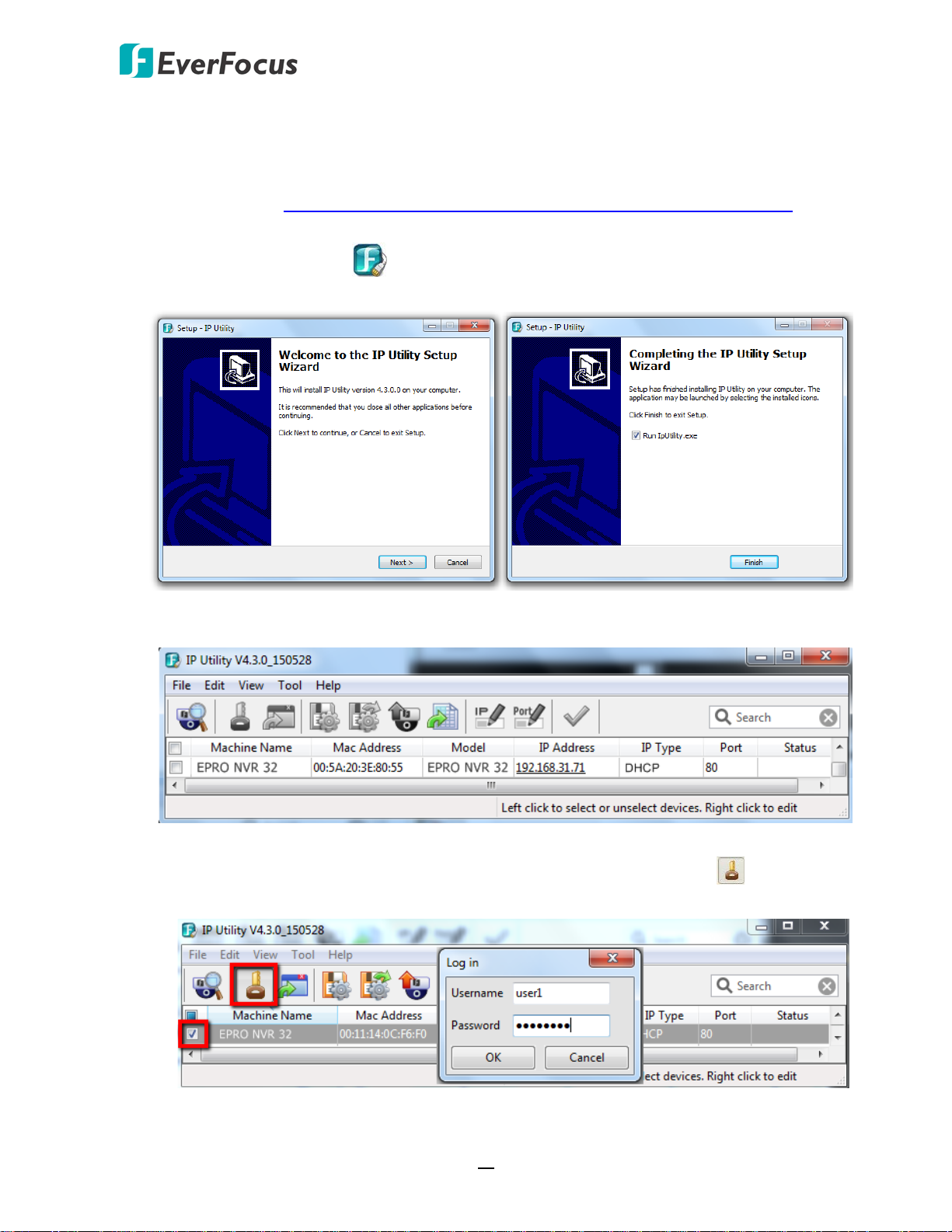
2.3 Accessing the Web Interface of NVR
You can look up the IP address and access the Web interface of the DVR using the IP Utility (IPU)
program, which is included in the software CD. The IP Utility can also be downloaded from
EverFocus’ Website: http://www.everfocus.com/HQ/Support/DownloadCenter_p1.aspx. Please
connect the DVR on the same LAN of your computer.
1. Save IP Utility Setup .exe in your computer. Double click the .exe file and follow the
on-screen instructions to install the IP Utility.
2. Click the Finish button, the IP Utility will be automatically launched to search the IP devices
connected on the same LAN.
3. To optionally configure the Machine Name, IP Address, IP Type or Port Number using the IPU:
a. Log in the DVR by checking the desired model and then click the Log in icon. The Log
in dialog box appears.
13
Page 23
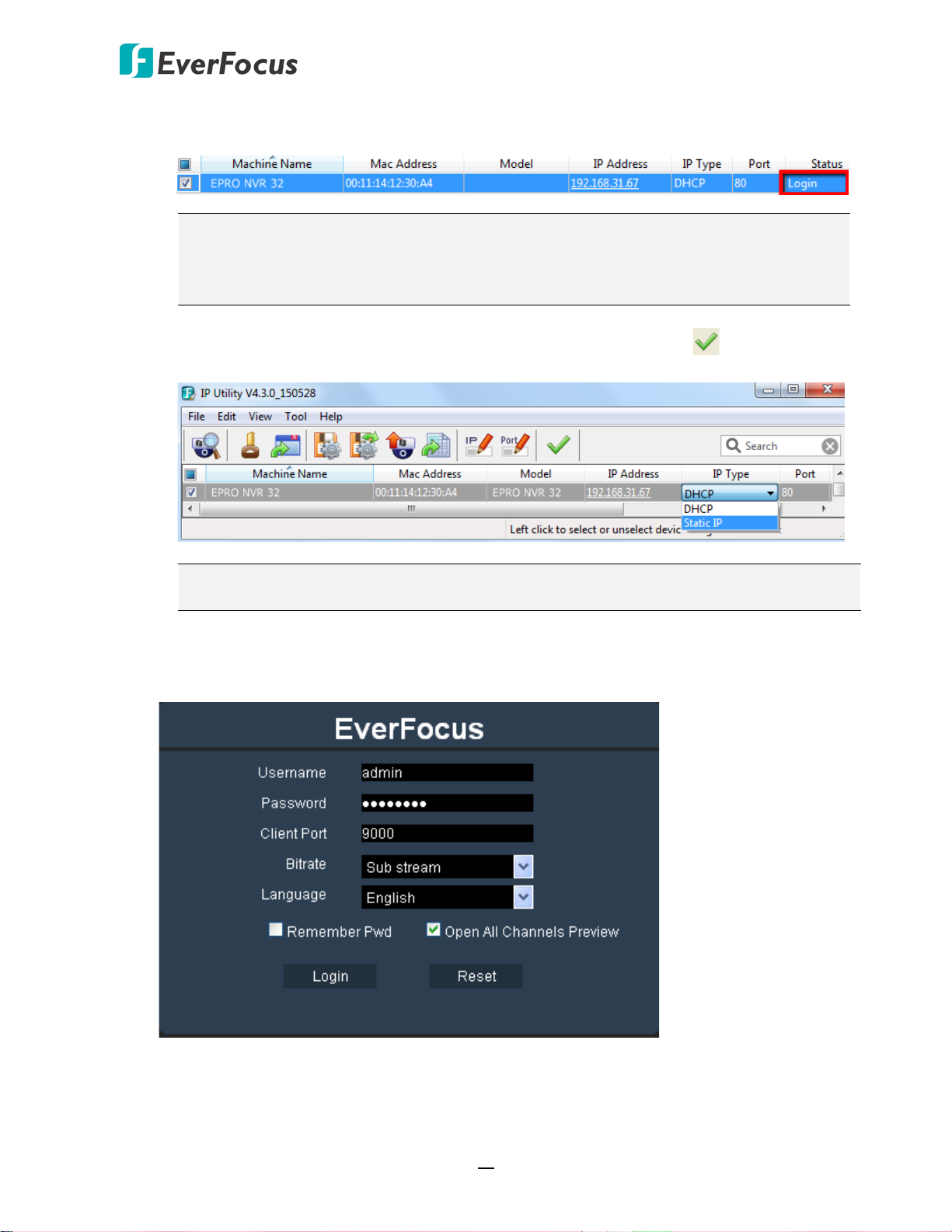
EPRO NVR Series
b. Type the Username and Password. Click the OK button, the status of the selected camera
will display Login.
Note:
1. The default user ID is admin and the default password is 11111111.
2. If you select more than one DVRs that have the same user ID / password, you will
be able to log in several DVRs at once.
c. Right click the column to configure the setting. Click Apply Changes button to apply
and save the settings.
Note: Most networks uses DHCP to assign IP address, if you are unsure of your network
settings, please consult your network administrators for configuration details.
4. To access the Live View window, double click the IP address of the desired device, the login
window pops up. Type the user ID and password to log in. By default, the user ID is admin
and the password is 11111111.
14
Page 24
EPRO NVR Series
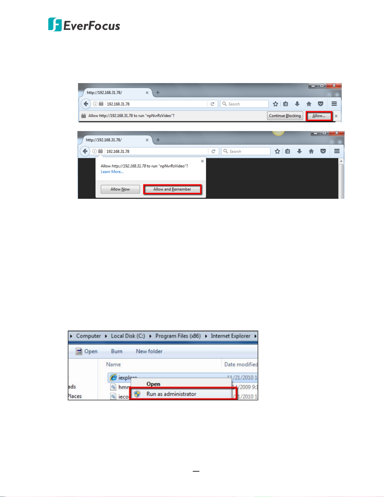
Note for the first time login:
When the Plug-in blocked appears on the browser, click Allow… and then click Allow
and Remember. Reload the webpage and you should see the remote live view page
now.
If you encounter the following problem or still can’t access the remote Web interface, please
follow the instructions below:
If the ActiveX is not downloaded successfully, please check if your browser’s safety level or
firewall setting is set too high. Enable the following options on the Security Settings
window (IE Browser < Tools < Internet Options < Security < Internet < Custom Level).
Automatic prompting for ActiveX controls
Script ActiveX controls marked safe for scripting
If your PC or laptop is running with Windows, it’s required to run the browser as
administrator when first entering the remote web page of the device. Go to C:\Program
Files (x86)\Internet Explorer, right-click the browser and then click Run as administrator.
15
Page 25
EPRO NVR Series
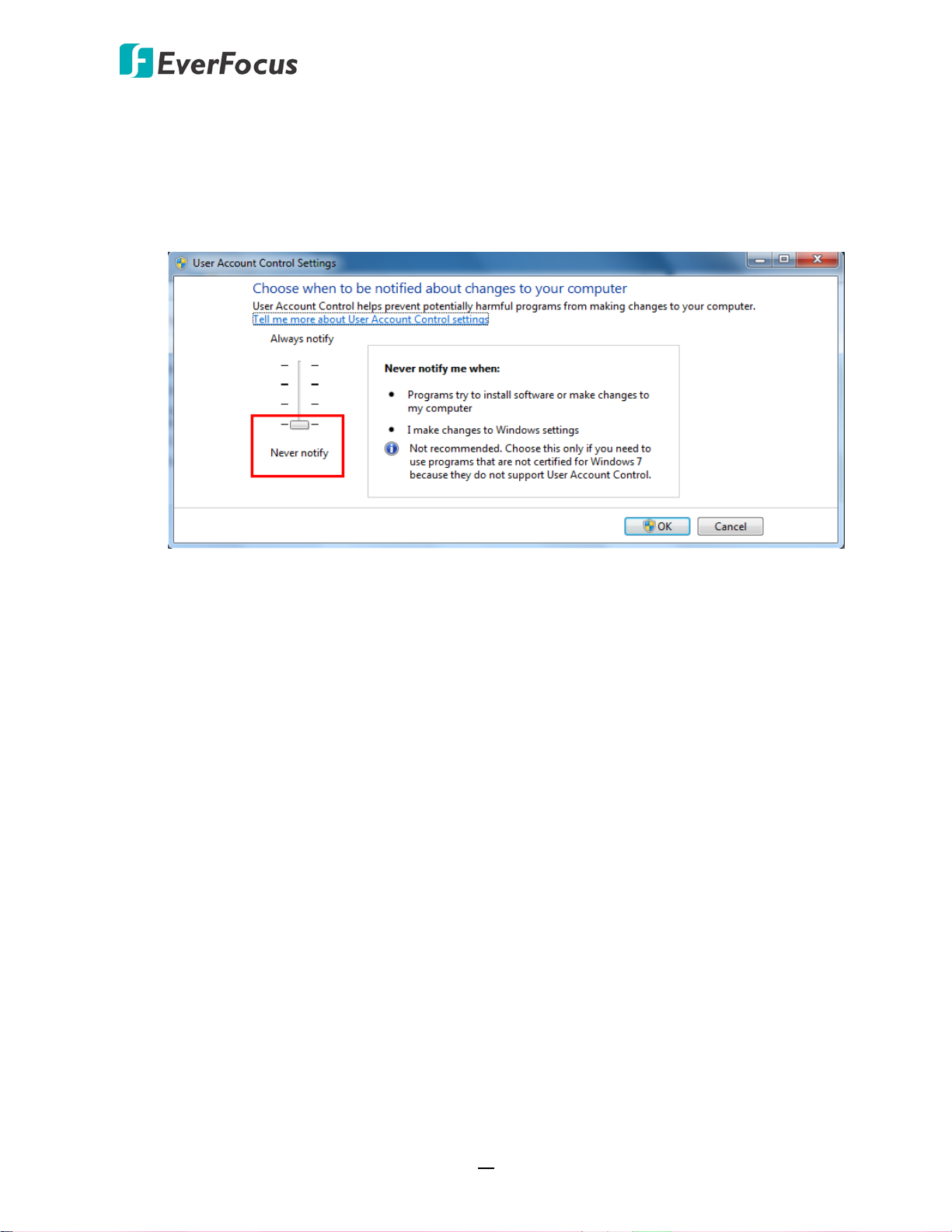
If you are unable to backup or record during remote operation, you may need to turn off
the firewall and turn User Account Control off.
To turn User Account Control off, on the computer, click Start > Control Panel > System
and Security > Action Center (click Change User Account Control Settings), the User
Account Control Settings window appears. Adjust the slide bar to Never Notify and then
click OK. Restart your computer if requested.
16
Page 26
EPRO NVR Series
3
Chapter
3. Getting Started
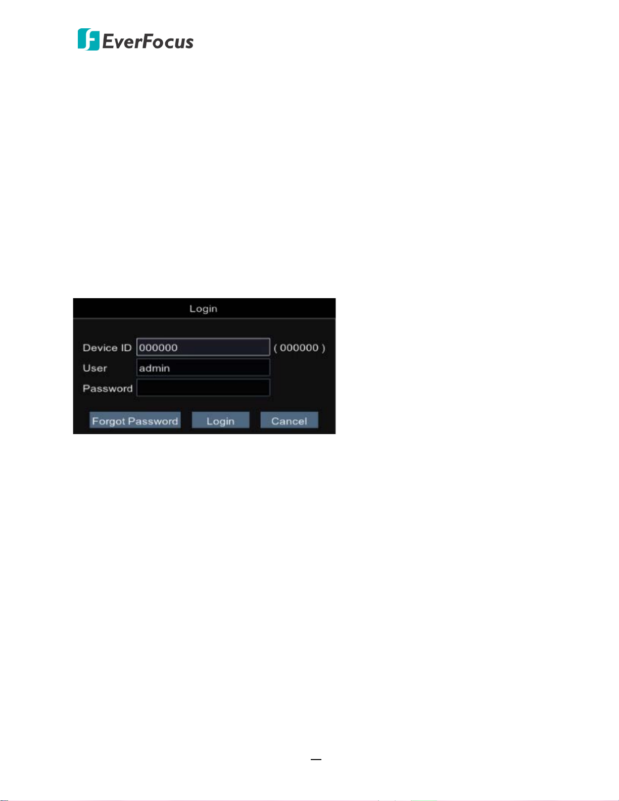
After pressing the power switch to turn on the NVR, the NVR will enter the System Initialization
process. When the process is done, the Login window will display. Input the Device ID / User Name
and Password. Click the Login button to login.
By default, the User Name is admin and Password is 11111111
After clicking the Login button, the Startup Wizard will be displayed to guide you through the basic
settings for the NVR. Click the Next button to proceed or Cancel to cancel the startup wizard.
Please refer to 3.1 Startup Wizard for more details.
3.1 Turning On / Off the Power
Before powering on the NVR, please make sure the internal HDD have been installed properly.
Once you have completed the basic cable connections, you are ready to turn on the NVR. Simply
plug in the power source and then press the Power Switch on the rear panel of the NVR to turn
on the NVR. The POWER LED will light up if power is normal. Once the system has finished
loading, you can begin to set up the menu options for the NVR.
17
Page 27
EPRO NVR Series
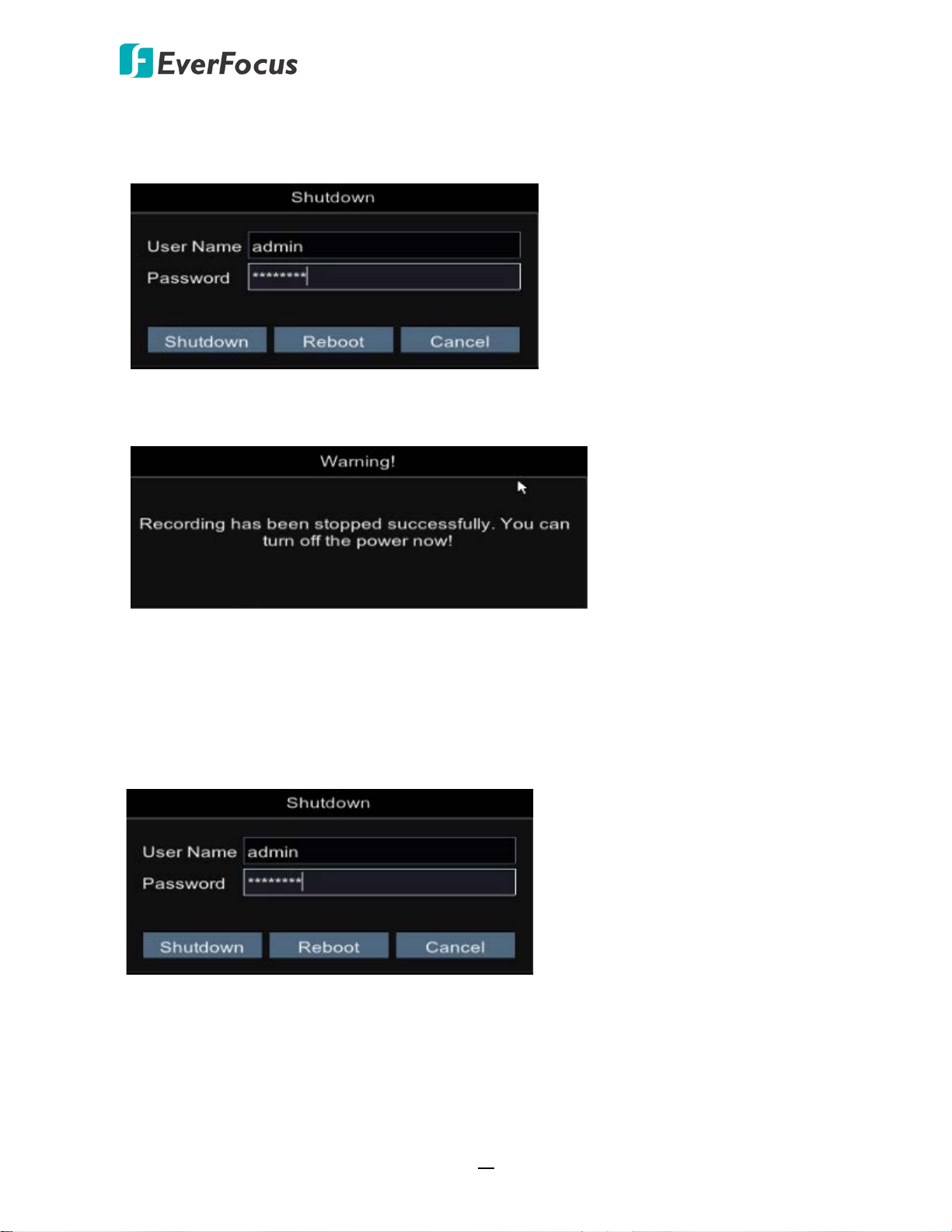
To turn off the power, right-click on the Live View window to bring up the OSD Root Menu and
then click Shutdown, the below Shutdown widow appears. Input the User Name, Password and
then click the Shutdown button to shutdown the NVR.
After clicking the Shutdown button, the below Warning window appears. Users can now press
the Power Switch on the rear panel of the NVR to turn off the power.
3.2 Restart the NVR
To restart the NVR, right-click on the Live View window to bring up the OSD Root Menu and then
click Shutdown, the below Shutdown widow appears. Input the User Name, Password and then
click the Reboot button to restart the NVR.
18
Page 28
EPRO NVR Series
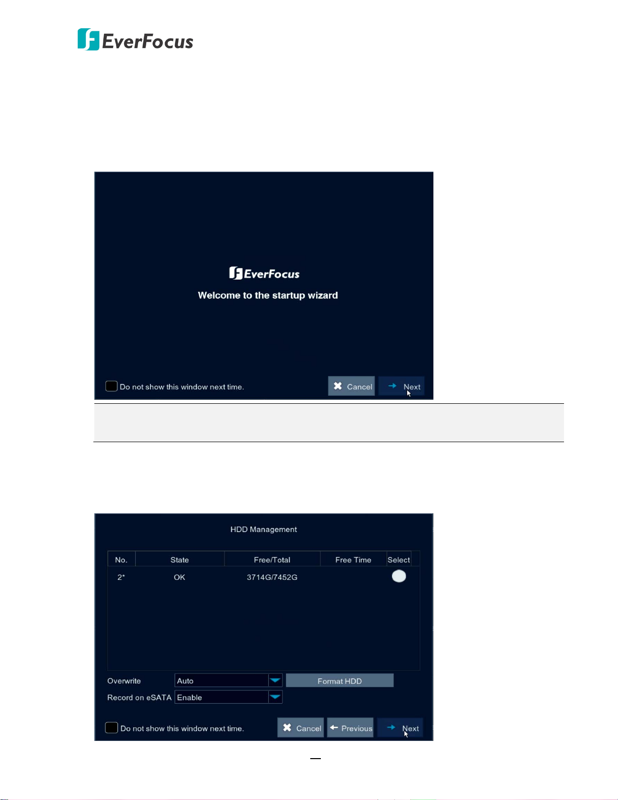
3.3 Startup Wizard
The Startup Wizard will guide you through some basic settings for the NVR. Please follow the onscreen instructions to proceed.
1. Click the Next button to start with the Startup Wizard.
Note: You can check “Do not show this window next time” if you do not want to run the
Startup Wizard to make any settings when you restart the NVR next time.
2. For the first time use HDD or a new HDD, users have to format the HDD before use. Click to
select the HDD in the Select column and then click Format HDD to format the selected HDD.
You can also setup to overwrite the HDD or Record on eSATA. Click Next to proceed.
19
Page 29
EPRO NVR Series
Note:
1. Please connect the HDDs to the system in advance.
2. Clicking the Format HDD button will effectively erase the entire data in the HDD! If you
do not want to format the HDD, click the Next button to proceed.
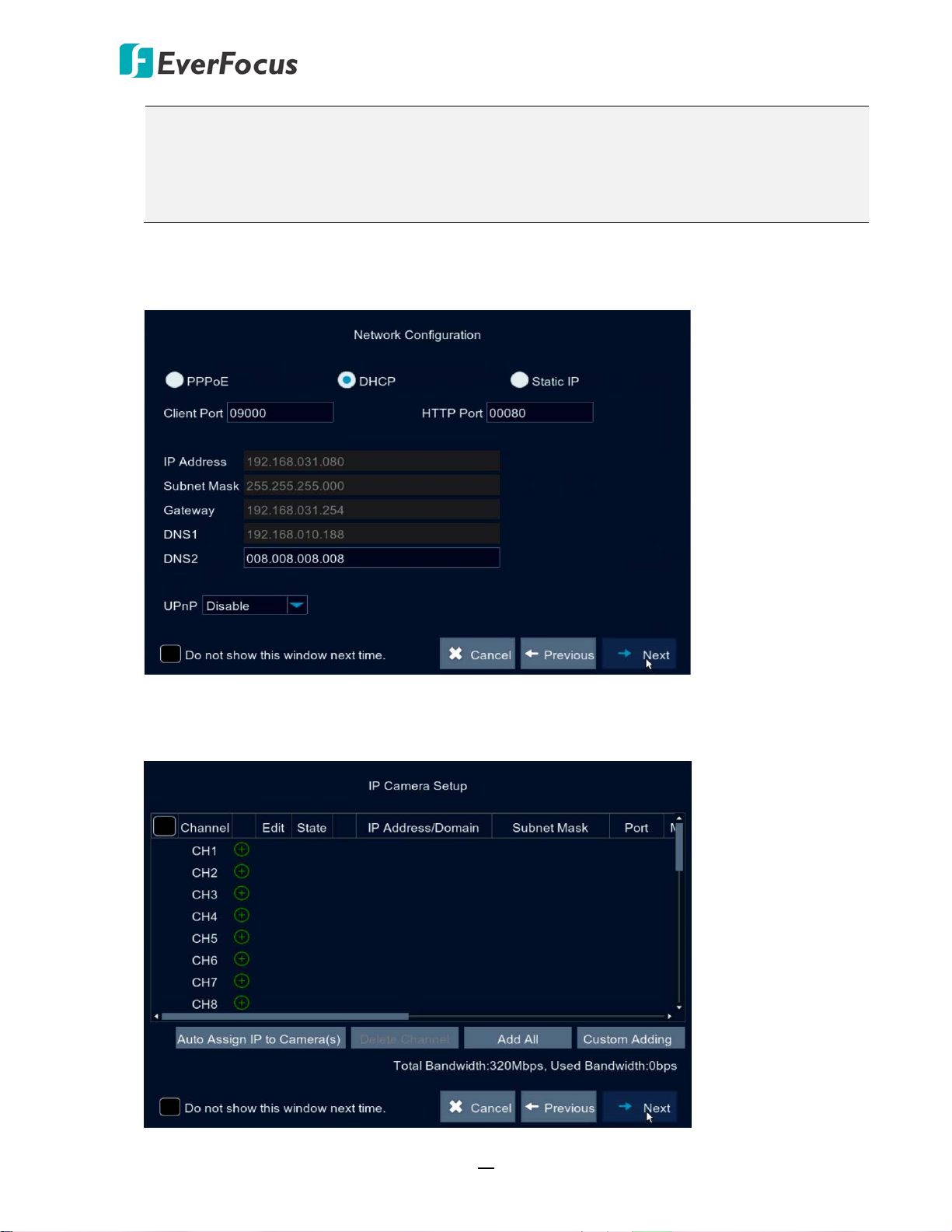
3. Configure the network settings. Select PPPoE, DHCP or Static IP and setup the settings. Click
Next to proceed.
4. You can add IP cameras on this page (please refer to 4.1.1.1.1. IP Channels for more details).
Click Next to proceed.
20
Page 30
EPRO NVR Series
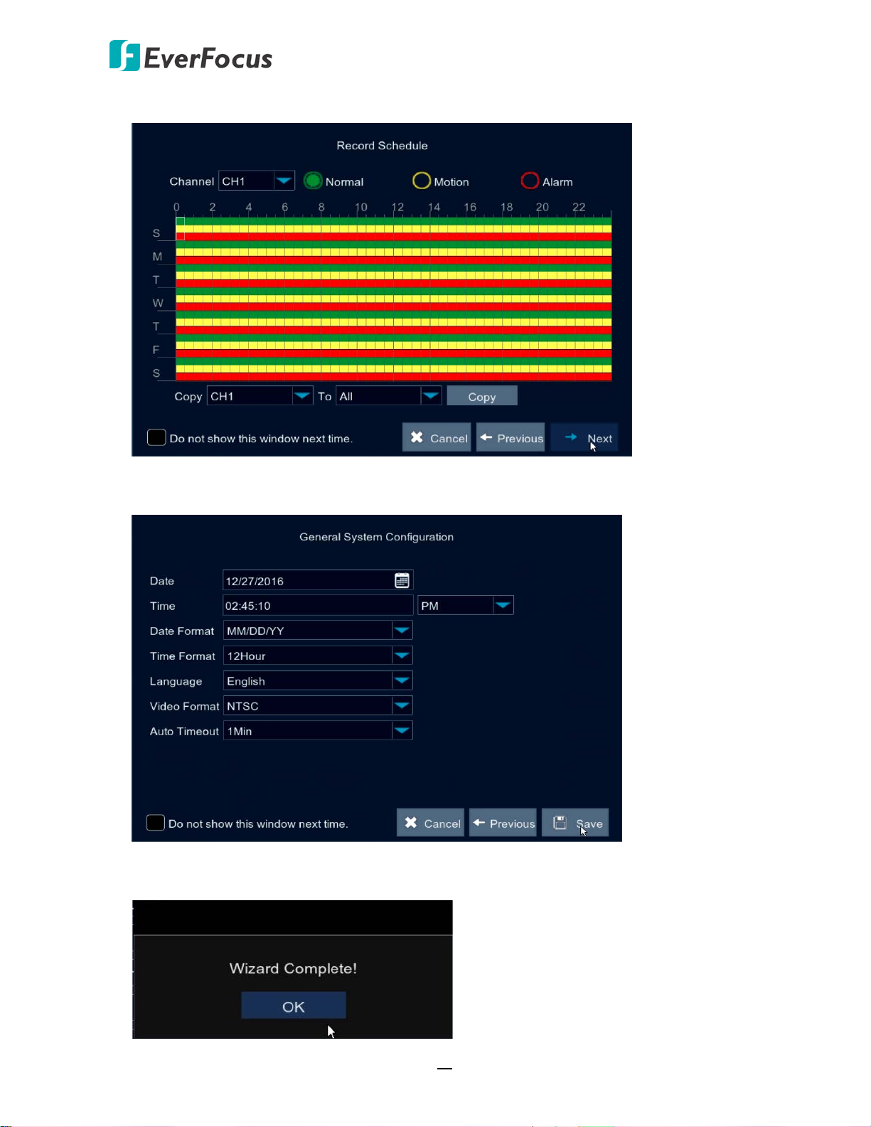
5. Configure the recording schedule. Click Next to proceed.
6. Configure the general system settings. Click Save to save the settings.
7. Click OK to complete the Startup Wizard.
21
Page 31

EPRO NVR Series
8. After clicking the OK button, the system will enter the Live View window (refer to 3.2 Live
View Window). Now you can start using the NVR.
Note:
1. If no HDD has been connected to the system, a warning message will pop-up. Click X to
close the warning message. If you want to perform the recording function, you will have
to connect the HDDs to the system.
2. If multiple HDDs have been connected to the system, the system will automatically
detect the connected HDDs when system starts up. The status of the connected HDDs
will be display in the Disk Warning window. Take the below image for example, HDD1 has
not been formatted; HDD2 is running normally (in recording state).
22
Page 32

EPRO NVR Series
1
2
3
4
5
7
8
6
2
3.4 Live View Window
No
Name Description
If the HDDs have been connected to the system, the system will
1 Record Icon
automatically start recording all the connected IP camera channels,
and the Record Icon will be displayed. If you want to configure the
record settings, please refer to 4.1.1.2 Record for more details.
Click the Previous / Next icon to turn to the previous / next layout
2 Layout Page Icon
pages. For example, if you select 9-Division, click the next layout page
icon (on the right side) will display the next 9-division layout with
channel 10-18.
Live Channel Tool
3
Bar
Left click any channel can display its Live Channel Tool Bar to perform
functions including manual record, quick playback, digital zoom, PTZ
and etc. Please refer to 3.3 Live Channel Tool Bar for more details.
You can drag and drop a channel to the desired position on the layout.
4 Drag Channel
Click on a channel, a Drag Channel icon will display. Drag and drop the
channel to the desired position on the layout.
If there is no HDD connected to the system, there will be a No HDD
5 No HDD Icon
icon displayed on the bottom of the window. Note that if you want to
perform the recording function, HDD(s) are required to be connected
to the system.
23
Page 33

EPRO NVR Series
1
2
3
4
5
6
Double click on a channel can display the channel in full screen. To
6 Live Channel
exit the full screen mode, double click on the channel again. In full
screen mode, you can right-click to bring up the Channel Tool Bar.
Please refer to 3.3 Channel Tool Bar for more details.
For channels without adding IP camera, a “No Camera” message will
be displayed on the channel. Right-click on the channel, a Quick Add
7 Quick Add
icon will be displayed. Click on the Quick Add icon will bring up the
Quick Add window. You can add an IP camera to this channel. Please
refer to Quick Add Window in 4.1.1.1.1 IP Channels for more details.
You can right click your mouse or move your mouse over the bottom
8 OSD Root Menu
of the screen to bring up the OSD Root Menu. Please refer to 4. OSD
Root Menu for more details.
3.5 Live Channel Tool Bar
You can left click any channel on the Live View Window to bring up its Live Channel Tool Bar.
No
Name Description
Click to switch between HD and SD stream to be displayed on the live
1 Stream Switch
view channel. To adjust the HD (main stream), SD (sub stream)
configurations, please refer to 4.1.1.2.3 Main Stream and 4.1.1.2.4
Sub Stream.
Click the button to start manual recording. Click the button again to
Start/Stop
2
Manual Record
3 Quick Playback
4 Zoom
stop manual recording.
Click to start the Quick Playback function. Click X to exit the Quick
Playback mode.
Click to start the digital zoom function. Please refer to 3.5.1 Digital
Zoom for more details.
Click to bring up the Image Setting window. You can adjust the
5 Image Settings
Sharpness, Brightness, Contrast and Saturation for each channel
individually.
6 PTZ
Click to bring up the PTZ Control window. Please refer to 3.5.2 PTZ
Control for more details.
24
Page 34

EPRO NVR Series
Live full screen channel Preview Window
Preview Window
Navigation Box
3.5.1 Digital Zoom
On the Live View window, left click on a channel to display its Live Channel Tool Bar and then
click the Zoom icon, the channel will be displayed in full screen.
To perform the digital zoom function:
1. Click on the image and then draw an area where you want to have a close-up view. A
preview window will display on the bottom right corner of the screen.
2. Drag the Navigation Box and drop it to the position where you want to have a close-up
view.
3. To re-draw an area, double click on the Live full screen channel.
4. To exit the Digital Zoom mode, right click the mouse.
5. To return to the Live View window, double click on the Live full screen channel.
25
Page 35

EPRO NVR Series
3.5.2 PTZ Control
You can control the connected PTZ camera using the PTZ Control window. On the Live View
window, select a PTZ camera by clicking on the channel, the selected channel will be
highlighted with a red frame and its Live Channel Tool Bar will be displayed. Click the PTZ
button to bring up the PTZ Control window. You can use your mouse to drag the PTZ Control
window and drop it to the desired position on the screen.
Channel Drop-Down List: Click to select a channel of PTZ camera you want to control.
Start Tour : Click to start the Tour function. Click again to stop the Tour function. Note that
for this function to work, users have to set up preset points in advance.
Speed: Slide the bar to the left or right to adjust the control speed.
Direction Buttons: Click the direction buttons to force the PTZ camera to turn to the direction.
Auto Pan : Click to start the Auto Pan function. Click again to stop the Auto Pan function.
Zoom: Click + or – to zoom in or zoom out.
Focus: Click + or – to focus near or focus far.
Iris: Click + or – to adjust the Iris.
Show Preset Window : Click to display or hide the Preset window. You can set up Preset
Points or perform the go to preset function on this window.
To set up Preset Points:
1. Select a preset number (1-255) by clicking on the No. input box.
2. Set up a dwell time for this preset number.
3. Use the direction buttons or Zoom/Focus/Iris buttons to search for the location for this
preset number.
4. Click the Set button to jump to the next preset number for configuration. Follow Step 2-3
to set up multiple preset points.
5. After setting up the preset points, click the Save button to save the settings.
6. To clear the setup preset points, select a preset number and then click Clear.
26
Page 36

EPRO NVR Series
To perform the Tour function:
1. Set up the preset points in advance. Please refer to the steps of “To set up Preset Points”
above.
2. Click the Start Tour button .
3. To stop the Tour function, click the Stop Tour button.
To perform the Go to Preset Point function:
1. Set up the preset points in advance. Please refer to the steps of “To set up Preset Points”
above.
2. Select a preset number (1-255) by clicking on the No. input box.
3. Click the Go button.
27
Page 37

EPRO NVR Series
4
Chapter
4. OSD Root Menu
To bring up the OSD Root Menu, right click your mouse or move your mouse over the bottom of
the screen, the OSD Root Menu displayed.
The images in this content are using the OSD of EPRO NVR 32 as examples. For EPRO NVR 16,
some of the OSD may look slightly different, such as the number of channels and layout options.
28
Page 38

EPRO NVR Series
1
2
3
4
5
6
7
8
9
10
11
12
13
14
15
No
Name Description
1 Main Menu
Manually Lock
2
Screen
Click to enter the Main setup page. Please refer to 4.1 Main Menu for
more details.
Click to lock or unlock the system interface. Please refer to 4.2
Lock/Unlock Screen for more details.
3 Quad Click to display quad view.
4 9 Divisions
Click to display the layout with 9 divisions.
5 12 Divisions Click to display the layout with 12 divisions.
6 16 Divisions Click to display the layout with 16 divisions.
7 25 Divisions Click to display the layout with 25 divisions.
8 36 Divisions Click to display the layout with 36 divisions.
9 More Layouts Click to select a desired layout to display.
10 Stream Switch Click to select Main Stream or Sub Stream for live view display.
11 Preview Policy
Start/Stop
12
Sequence
Click to select a live view quality. The options include Realtime,
Balanced and Smooth.
Click the button to start displaying the sequence mode. Click again to
stop the sequence mode. To configure the sequence settings, please
refer to 4.1.1.1.3 Output.
13 Volume Click to adjust the volume.
14 Playback
Click to enter the playback page. Please refer to 4.1.2 Record Search for
more details.
15 Info Click to display the system info.
29
Page 39

EPRO NVR Series
4.1 Main Menu
You can configure most of the system settings on the Main Menu.
4.1.1 Settings
On the Settings page, you can configure the Display, Record, Network and Alarm settings.
4.1.1.1 Display
On this page, you can configure IP Channels, Live, Output and Privacy Mask.
4.1.1.1.1 IP Channels
You can add IP cameras manually or automatically using this page.
Auto Assign IP to Camera(s): Click to automatically search the IP cameras on the same LAN
and then automatically assign IP addresses to the IP cameras. The IP cameras will be
automatically added to the NVR as well.
Delete Channel: Select the desired IP cameras and then click this button to delete the
selected IP cameras.
Auto Add All: Click to automatically search the IP cameras on the same LAN. The IP cameras
will be automatically added to the NVR.
Custom Adding: Click to add IP cameras through RTSP protocol to the NVR. Please refer to
Custom Adding in the following content for more details.
30
Page 40

EPRO NVR Series
You can also click the following icons to perform the functions:
Delete: Click to delete the IP camera.
Add: Click to bring up the Quick Add window to add an IP camera. Please refer to Quick
Add window below for more details.
Edit: Click to edit IP camera profile.
Modify: Click to modify IP camera settings.
Click Cancel to cancel and leave the page.
Quick Add Window
After clicking the Add button , the Quick Add window appears.
To quickly add an IP camera to this channel:
1. Click the Search button to search for the IP cameras on the same LAN. Note that the IP
cameras that have been added to the NVR will not be displayed.
2. Select an IP camera from the list by clicking on it, the selected IP camera will be
highlighted with a blue background and its IP address will be automatically displayed in
the right-side field.
3. Input the User Name and Password of the IP camera. Configure the Alias, Position and
Protocol if necessary.
4. Click the Add button, the IP camera will be added to the channel.
31
Page 41

EPRO NVR Series
2 3
1
Custom Adding
After clicking the Custom Adding button, the Custom Adding window appears. The
Custom Adding window can be divided into three sections:
Section 1: Displays the searched IP cameras on the same LAN.
The system will automatically search the IP cameras on the same LAN and lists the IP
cameras that have not been added to the system here.
Section 2: Configure the info of the IP camera selected in Section 1.
Click an IP camera on the Section 1 list, the clicked IP camera will be highlighted with a
blue background and its IP address will be displayed in the IP Address/Domain input box
automatically. You can further input the information of the IP camera in this section.
Section 3: Displays the IP cameras already added to the system.
The IP cameras that have been added to the system will be listed here. You can check
the box to select the IP cameras and then click the Delete Channel button to delete the
selected IP cameras.
Note: The Protocol drop-down list in Section 2 includes three protocols: Private, ONVIF
and Custom. Depends on the IP cameras, users can add the IP cameras through
Private, ONVIF or RTSP (Custom 1-16) protocol. To configure multiple RTSP protocol to
Custom 1-16, click the Manage Protocol button to bring up the Manage Protocol
window. Please refer to Manage Protocol in the following content for more details.
32
Page 42

EPRO NVR Series
Manage Protocol: Click to bring up the Manage Protocol window. You can configure
Custom 1-16 RTSP streaming protocol on this page.
• Custom Protocol: Select a custom RTSP protocol profile from the drop-down list to
be configured. Up to 16 profiles can be configured.
• Protocol Name: Input a name for this RTSP protocol profile.
• Stream Type: Indicates Main Stream and Sub Stream are supported. You can
separately configure the Main Stream and Sub Stream settings below.
• Enable Sub Stream: Check the Sub Stream checkbox if you want to enable sub
stream for this RTSP protocol.
• Type: Select RTSP.
• Port: Keep 554 as the RTSP port.
• RTSP URL: Input the RTSP URL syntax in the box. For example:
rtsp://[IP Address]:[Port]/ch[A]/[B]
rtsp://192.168.31.33:554/ch01/0
* IP Address: The IP address of the NVR
* A: Channel number. 01 (ch1), 02 (ch2), and so on
* B: Stream Type: 0 (main stream), 1 (sub stream)
Search: Click to search the IP cameras on the same LAN. The searched IP cameras will
be displayed on the Section 1 list. Note that the IP cameras that have been added to the
NVR will not be displayed on this list.
Add: Click to add the single selected IP camera to the system. Select an IP camera from
the Section 1 list by clicking on it, the selected IP camera will be highlighted with a blue
background and its info will be displayed on Section 2. You can edit the IP camera info
in Section 2. Click the Add button, the IP camera will be added to the system. You can
see this IP camera listed on Section 3 list.
Add Selected: Click to add the multiple selected IP cameras to the system. Select the
desired IP cameras from the Section 1 list by checking the checkboxes and then click the
33
Page 43

EPRO NVR Series
Add Selected button, the IP cameras will be added to the system. You can see the IP
cameras listed on Section 3 list.
Delete Channel: Click to delete the IP cameras from the system. Select the IP cameras
by checking the checkboxes from the list in Section 3 and then click the Delete Channel
button. The selected IP cameras will be deleted from the system.
Cancel: Click to cancel and leave the page.
4.1.1.1.2 Live
You can configure camera OSD or image settings on this page.
Channel: Select a channel from the drop-down list.
Channel Name: Input a name for the IP camera.
Show Name: Select Enable if you want to display camera name on the live stream.
Record Time: Select Enable if you want to display time on the live stream.
Date Format: Select a date format from the drop-down list.
Time Format: Select a time format from the drop-down list.
Refresh Rate: Select 50Hz or 60Hz from the drop-down list.
OSD Position: Click to set up the OSD position freely.
Image: Click to adjust image configurations including Sharpness, Brightness, Contrast and
Saturation.
Click Save to save the settings or Cancel to cancel and leave the page.
34
Page 44
EPRO NVR Series
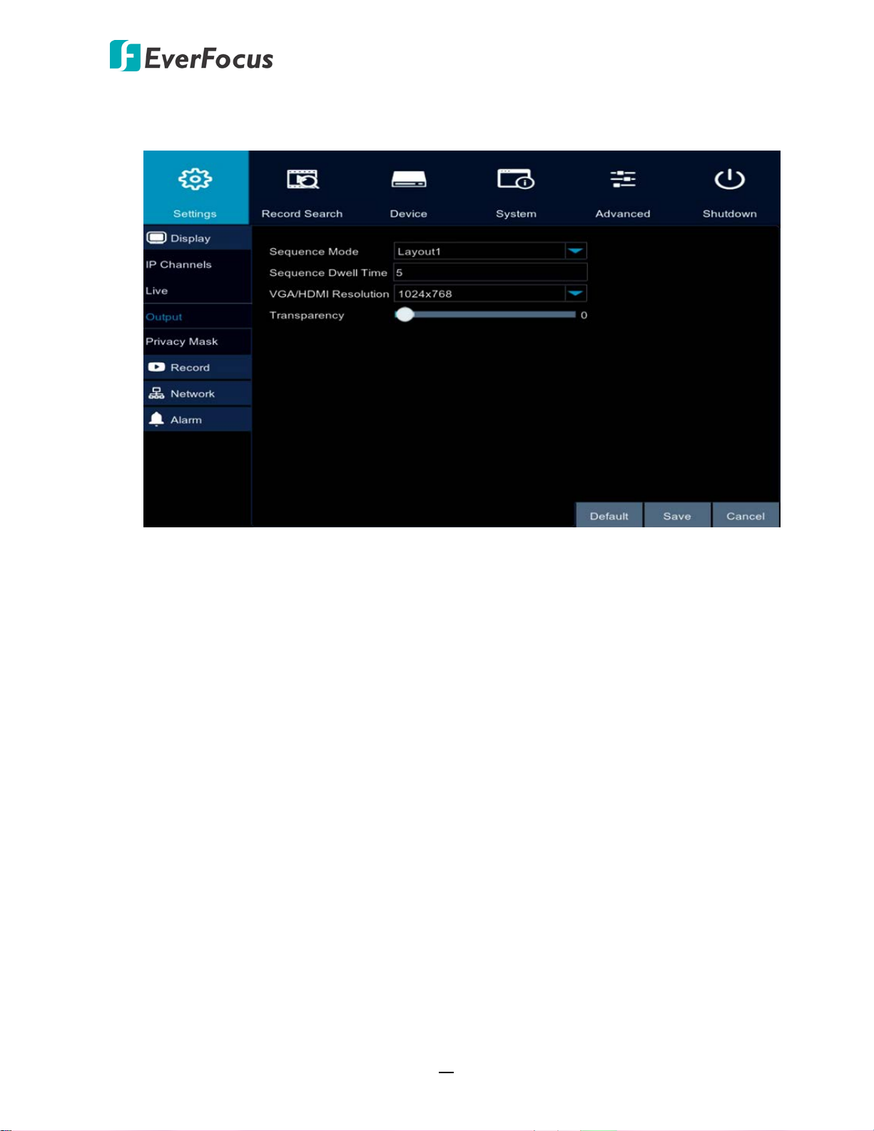
4.1.1.1.3 Output
You can configure the output monitor settings and OSD menu transparency on this page.
Video output: Select Live Output from the drop-down list.
Sequence Mode: Select a layout for the sequence mode. For example, if you select Layout4,
the NVR will display a quad view layout for the 32 channels in sequence order. To start the
sequence mode, on the Live View screen, click the Start Sequence icon on the OSD Root
menu. Click the button again to stop sequence mode.
Sequence Dwell Time: Select a sequence dwell time in second. By default, 5 seconds is set
up.
VGA/HDMI Resolution: Select a live resolution to be displayed on the output monitor.
Transparency: Set up the transparency for the OSD menu.
Click Default to return to factory default value, Save to save the settings, or Cancel to cancel
and leave the page.
35
Page 45

EPRO NVR Series
4.1.1.1.4 Privacy Mask
The Privacy Mask can block out sensitive areas from view. This feature is useful when users’
don’t want the sensitive information visible. Up to four Privacy Masks can be configured.
To configure privacy masks:
1. Select a channel from the Channel drop-down list.
2. Select Enable from the Mask Area drop-down list.
3. Select the number of masks to be configured. Up to 4 masks are available.
4. Click the Setup button to adjust the masks position. After setting up the position, right
click the mouse to return to the Privacy Mask page.
5. Click Save to save the settings.
36
Page 46

EPRO NVR Series
4.1.1.2 Record
You can configure the record settings on this page.
4.1.1.2.1 Record
You can configure the basic record settings on this page.
Channel: Select a channel to configure the record setting individually.
Record Switch: Select Enable to enable the record function.
Stream Mode: Select Main Stream or Sub Stream to record on this channel.
Pre-Record: Select Enable to enable pre-recording for motion detection or I/O trigger record.
Copy: You can apply the same configurations from one channel to the desired channels.
Select a channel from the Copy drop-down list first and then select a desired channel (or All)
from the To drop-down list, click the Copy button, the selected channel(s) will be applied
with the same configurations.
Click Default to return to factory default value, Save to save the settings, or Cancel to cancel
and leave the page.
37
Page 47

EPRO NVR Series
4.1.1.2.2 Record Schedule
You can configure the record schedule on this page.
Channel: Select a channel to configure the record schedule setting individually.
Normal: Click the Normal button and then move your mouse cursor over the schedule time
blocks. Click and drag on the schedule time blocks to draw the blocks with green color,
which will be applied with normal recording function.
Motion: Click the Motion button and then move your mouse cursor over the schedule time
blocks. Click and drag on the schedule time blocks to draw the blocks with yellow color,
which will be applied with motion recording function.
Alarm: Click the Alarm button and then move your mouse cursor over the schedule time
blocks. Click and drag on the schedule time blocks to draw the blocks with red color, which
will be applied with alarm recording function.
Copy: You can apply the same configurations from one channel to the desired channels.
Select a channel from the Copy drop-down list first and then select a desired channel (or All)
from the To drop-down list, click the Copy button, the selected channel(s) will be applied
with the same configurations.
Click Default to return to factory default value, Save to save the settings, or Cancel to cancel
and leave the page.
38
Page 48

EPRO NVR Series
4.1.1.2.3 Main Stream
You can configure the main stream record, resolution and etc. for individual channel.
Channel: Select a channel to apply with the following configurations.
Resolution: Select a recording resolution for the selected channel.
FPS: Select a record FPS (frames per second) for the selected channel.
Bitrate Control: Select CBR (constant bitrate) or VBR (variable bitrate) for the selected
channel. If VBR is selected, select a quality type from the drop-down list next to Bitrate
Control.
Bitrate Mode: Select User-defined or Predefined for the selected channel.
Bitrate: Set up a bitrate for the selected channel.
Click Save to save the settings, or Cancel to cancel and leave the page.
39
Page 49

EPRO NVR Series
4.1.1.2.4 Sub Stream
You can configure the sub stream record, resolution and etc. for individual channel.
Channel: Select a channel to apply with the following configurations.
Resolution: Select a recording resolution for the selected channel.
FPS: Select a record FPS (frames per second) for the selected channel.
Bitrate Control: Select CBR (constant bitrate) or VBR (variable bitrate) for the selected
channel. If VBR is selected, select a quality type from the drop-down list next to Bitrate
Control.
Bitrate Mode: Select User-defined or Predefined for the selected channel.
Bitrate: Set up a bitrate for the selected channel.
Click Save to save the settings, or Cancel to cancel and leave the page.
40
Page 50

EPRO NVR Series
4.1.1.2.5 Mobile Stream
You can configure the mobile stream record, resolution and etc. for individual channel.
Channel: Select a channel to apply with the following configurations.
Enable: Select Enable from the drop-down list to enable the function.
Resolution: Select a recording resolution for the selected channel.
FPS: Select a record FPS (frames per second) for the selected channel.
Bitrate Control: Select CBR (constant bitrate) or VBR (variable bitrate) for the selected
channel. If VBR is selected, select a quality type from the drop-down list next to Bitrate
Control.
Bitrate Mode: Select User-defined or Predefined for the selected channel.
Bitrate: Set up a bitrate for the selected channel.
Click Save to save the settings, or Cancel to cancel and leave the page.
41
Page 51

EPRO NVR Series
4.1.1.3 Network
You can configure the network settings on this page.
4.1.1.3.1 Network
You can configure the basic network settings on this page. After configuring the settings,
users are able to control and monitor the NVR remotely.
PPPoE: This is a DSL-connection application. The ISP will ask the user to input a username
and password. Contact your ISP for these details.
Note: If PPPoE is selected as the IP type, the supplied IP Utility program will not be able to
detect the device.
DHCP: DHCP server in LAN will automatically assign an IP configuration for the network
connection. This setting lets the system use an automatically assigned (dynamic) IP address.
This address can change under certain circumstances, for instance, when the NVR’s network
switch/hub has to be rebooted.
Static IP: Users can manually set up a Static IP address for the NVR. This type of address is
stable and cannot change, but users have to make sure there are no IP address conflicts with
other network-connected devices.
Client Port: Keep 9000 port. Change only when necessary.
HTTP Port: Keep 80 port. Change only when necessary.
UPnP: If you want to enable the UPnP function, click Enable from the drop-down list.
Click Default to return to factory default value, Save to save the settings, or Cancel to cancel
and leave the page.
42
Page 52

EPRO NVR Series
4.1.1.3.2 Email
You can configure the email settings on this page.
Email: Select Enable to enable the Email function.
Encryption: Select Enable if you want to enable the Encryption function.
SMTP Port: Assign the port number used by the SMTP server.
SMTP Server: Assign the SMTP (Email) server’s name. Note that for more reliable email
service, use the server’s IP address.
Sender: Input the Email address of the sender (the NVR). Sender’s Email address has to
match the password below.
Sender Password: Input the password of the sender.
Receiver: Input the Email address of the receiver.
Interval: Configure an interval to send Emails when events occur.
Test Email: Click to test whether the Email function is working normally.
Click Default to return to factory default value, Save to save the settings, or Cancel to cancel
and leave the page.
43
Page 53

EPRO NVR Series
4.1.1.3.3 Email Schedule
You can configure the email schedule on this page. The selected event Email alerts will be
sent out by the scheduled time. For example, if you set up Motion on Sunday between 68am, the Motion Email alerts will only be sent out between 6-8am on Sunday.
Channel: Select a channel to configure the email schedule individually.
Motion: Click the Motion button and then move your mouse cursor over the schedule time
blocks. Click and drag on the schedule time blocks to draw the blocks with green color,
which will be applied with motion email alert function.
Alarm: Click the Alarm button and then move your mouse cursor over the schedule time
blocks. Click and drag on the schedule time blocks to draw the blocks with yellow color,
which will be applied with alarm email alert function.
Exception: Click the Exception button and then move your mouse cursor over the schedule
time blocks. Click and drag on the schedule time blocks to draw the blocks with red color,
which will be applied with exception email alert function.
Copy: You can apply the same configurations from one channel to the desired channels.
Select a channel from the Copy drop-down list first and then select a desired channel (or All)
from the To drop-down list, click the Copy button, the selected channel(s) will be applied
with the same configurations.
Click Default to return to factory default value, Save to save the settings, or Cancel to cancel
and leave the page.
44
Page 54

EPRO NVR Series
4.1.1.3.4 DDNS
You can configure the DDNS setting on this page. DDNS (Dynamic Domain Name System) is a
service used to map a domain name to the dynamic IP address of a network device. You can
set up the DDNS service for remote access to the NVR.
DDNS assigns a domain name (URL) to the NVR, so that the user does not need to go
through the trouble of checking if the IP address assigned by DHCP Server has changed.
Once the IP is changed, the NVR will automatically update the information to the DDNS to
ensure it is always available for remote access.
Note that before enabling the following DDNS function, user should have applied for a host
name from the DDS service provider’s website.
DDNS: Select Enable from the DDNS drop-down list to enable DDNS function.
Server: Select a DDNS service provider from the drop-down list.
Doman: Input the domain name obtained from the DDNS service provider. Note that before
enabling the following DDNS function, user should have applied for a host name from the
DDS service provider’s website.
User: Input the user name of the DDNS account.
Password: Input the password of the DDNS account.
Test DDNS: Click the button to test whether the DDNS function is working normally.
Click Default to return to factory default value, Save to save the settings, or Cancel to cancel
and leave the page.
45
Page 55

EPRO NVR Series
4.1.1.3.5 RTSP
You can configure the RTSP setting on this page.
RTSP Enable: Select Enable from the drop-down list to enable the RTSP function.
Verify: Select Enable from the drop-down list to enable the verify function.
RTSP Port: Keep 554 as RTSP port.
RTSP URL Syntax:
rtsp://[IP Address]:[Port]/ch[A]/[B]
rtsp://192.168.31.33:554/ch01/0
* IP Address: The IP address of the NVR
* A: Channel number. 01 (ch1), 02 (ch2), and so on.
* B: Stream Type: 0 (main stream), 1 (sub stream)
Click Default to return to factory default value, Save to save the settings, or Cancel to cancel
and leave the page.
46
Page 56

EPRO NVR Series
4.1.1.4 Alarm
You can configure the motion and alarm settings on this page.
4.1.1.4.1 Motion
You can configure the Motion setting on this page.
Channel: Select a channel to apply with the motion detection function.
Enable: Select Enable from the drop-down list to enable the function.
Buzzer: Select a buzzer sound duration from the drop-down list. If you want to disable the
buzzer, select Disable from the drop-down list.
Sensitivity: Select a sensitivity value from the drop-down list. The larger the value, the
higher the sensitivity.
Area: Click to set up the motion detection area. Drag a rectangle with your mouse. The
selected areas will be highlighted in red and are applied with the motion detection function.
47
Page 57

EPRO NVR Series
Post Recording: Select a post recording time when motion events occur.
Latch Time: Select a latch time (duration) when motion events occur. When a motion object
is detected, the alarm will last based on the latch time.
Alarm Out: Check the box to enable the alarm output.
Show Message: Check the box to enable the function. When an event occurs, an event
message will be displayed on the live screen.
Send Email: Check the box to enable the function. When an event occurs, the NVR will send
an email alert to the receiver. Note that for this function to work, you have to set up the
Email function in advance (refer to 4.1.1.3.2 Email).
Full Screen: Check the box to enable the function. When an event occurs, the corresponding
channel with the event will be switched to full screen on the live screen.
Record Channel: Check the box to enable the function. When an event occurs, the selected
channel(s) will be recorded.
Click Save to save the settings, or Cancel to cancel and leave the page.
4.1.1.4.2 Alarm
You can configure the Alarm setting on this page.
Alarm In: Select an alarm input from the drop-down list.
Alarm Type: Select an alarm type. N.O or N.C. If you want to disable the alarm, select Off.
Latch Time: Set up the time for buzzer to sound when an alarm is triggered by external
sensor.
48
Page 58

EPRO NVR Series
Buzzer: Set up the time for buzzer to sound when an alarm is triggered.
Post Recording: Select a post recording time when an alarm is triggered.
Alarm Out: Check the box to enable the alarm output.
Show Message: Check the box to enable the function. When an alarm is triggered, an alarm
message will be displayed on the live screen.
Send Email: Check the box to enable the function. When alarm is triggered, the NVR will
send an email alert to the receiver. Note that for this function to work, you have to set up
the Email function in advance (refer to 4.1.1.3.2 Email).
Full Screen: Check the box to enable the function. When alarm is triggered, the
corresponding channel with the alarm will be switched to full screen on the live screen.
Record Channel: Check the box to enable the function. When alarm is triggered, the selected
channel(s) will be recorded.
Copy: You can apply the same configurations from one channel to the desired channels.
Select a channel from the Copy drop-down list first and then select a desired channel (or All)
from the To drop-down list, click the Copy button, the selected channel(s) will be applied
with the same configurations.
Click Default to return to factory default value, Save to save the settings, or Cancel to cancel
and leave the page.
The alarm types and descriptions are listed as below:
Alarm Type Functions and Descriptions
Video Loss When NVR fails to receive video signals due to some problems (camera
damage, cable dropout or damage, power failure), the alarm will appear.
Motion
Detection
When IP camera detects moving objects, alarm will be triggered. Sensitivity
is subject to the actual application environment test. Sensitivity is adjusted
according to the sensitivity of moving object detection and parameters are
modified by combining the area setting.
I/O Status Communicate with alarm device through I/O port. Alarm signals sent by IR
sensor or other devices will be transformed to the system recognized signal
and activate relevant channel to record or control the device output.
HDD Status Alarm will appear when HDD does not work due to damage, power failure,
HDD auto-overwrite off and insufficient space.
49
Page 59

EPRO NVR Series
4.1.2 Record Search
You can search and then play back the recordings or search the event logs on this page.
4.1.2.1 General
You can search and then play back the recordings on this page.
Channel: Select the desired channel(s) you want to search for playback.
Type: Select the desired event types from the drop-down list.
Search: After selecting the channel/event type and date, click the Search button to search
for the recordings.
Calendar: Select the month and year and click a date on the calendar. The date marked with
an orange triangle indicates there are recordings on the date.
Playback Channels: Select the desired channels for playback. The channel(s) marked with an
orange triangle indicates there are recordings on the channel(s). Up to 16 channels can be
selected.
Start Time: Select a start time.
End Time: Select an end time.
Play: Click the Play button to enter the playback mode and start playing back. Please refer to
4.1.2.1.1 Playback Mode for more details.
Click Cancel to cancel and leave the page.
50
Page 60

EPRO NVR Series
1 2
3
4 5
6
7 8
9
10
11
12
13
14
4.1.2.1.1 Playback Mode
On the Record Search < General page, click the Play button to enter the playback mode. To
exit playback mode, click the X button on the upper right corner of the screen.
You can use the playback control bar to operate the below functions:
No. Name Description
1 Pin Click to pin or unpin the left-side panel and playback control bar.
Click to start rewind. You can adjust the speed by continuously
2 Rewind
clicking on the button. The speed will be displayed on the upperright corner of the screen.
Click to start slow playback. You can adjust the speed by
3 Slow Play
continuously clicking on the button. The speed will be displayed on
the upper-right corner of the screen.
4 Play Click to start playing back.
5 Pause Click to pause playing back.
51
Page 61

EPRO NVR Series
No. Name Description
6 Stop Click to stop playing back.
Click to start playing fast forward. You can adjust the speed by
7 Fast Forward
continuously clicking on the button. The speed will be displayed on the
upper-right corner of the screen.
Select a channel by clicking on the channel on the screen. The selected
channel will be highlighted with a red frame. Click the Zoom button, the
selected channel will be switch to single view. Click to draw a rectangle
8 Zoom
area on the channel where you want to zoom in using your mouse, a
preview PIP window appears on the lower-right screen. You can drag
the navigation window in the PIP window to navigate the stream view.
To exit the zoom mode, click the zoom button again.
Select a channel by clicking on the channel on the screen. The selected
channel will be highlighted with a red frame. Click the scissor button
, the button will change to a save button , and the red time
period icons appear on the time bar. Drag the time period icons to the
left or right to adjust the time period and then click the save button to
9 Backup
start backing up. For more details on Backup, please refer to 4.1.2.2.1
Backup.
To exit the backup mode, click the scissor button again.
10 Volume
Click to enable/disable volume sound. You can also adjust the volume
bar.
11 Time Indicator Indicates the current playback time.
You can use your mouse to drag the time bar to the left or right to
12 Time Bar
search the desired time for playing back. Double click on the time bar at
a certain time will start playing back from the clicked time. The colors
on the time bar represent different recording types.
13 Time Span You can click to select a time span.
The colors indicate the recording types.
Yellow: Motion recordings.
14 Color
Green: Normal recordings.
Blue: I/O recordings.
Red: Alarm recordings.
52
Page 62

EPRO NVR Series
Playback Type: General
Playback Type: Events
The orange triangle mark indicates
there are recordings on the date.
Select a playback type.
General: Select the desired
channels and then play back.
Events: Select the desired time,
channels and event types and
then play back.
If Events is selected from the
Playback Type drop-down list,
after searching for the desired
event recordings, click this button
to back up the recordings.
4.1.2.2 Events
You can search the event recordings and then play back the event recordings on this page.
53
Page 63

EPRO NVR Series
Previous
Jump
Next
Date: Select the desired date.
Time: Select the desired time period.
Channel: Select the desired channel(s).
Type: Select the desired event types from the drop-down list.
Quick Backup: After selecting the date/time/channel/event type parameters, click the Quick
Backup button to back up all the searched recordings.
Search: After selecting the date/time/channel/event type parameters, click the Search
button and the searched event recordings will be displayed on the below list.
Backup: If you want to back up a single recording or some of the desired recordings, check
the recording boxes and then click the Backup button.
Cancel: Click to cancel and leave the page.
You can use the below buttons to search for the page on the list. To jump to a certain page,
input a page number in the input box and then click the Jump button.
To play back a certain event recording on the list, double click on a recording or click the
Playback icon in the Playback column to enter the playback mode. About the playback
control bar, please refer to 4.1.2.1.1 Playback Mode. To exit the playback mode, right click
the mouse.
54
Page 64

EPRO NVR Series
4.1.2.2.1 Backup
You can click the Quick Backup button to back up all the searched recordings on the list; or
click the Backup button to back up the selected recordings on the list.
1. Ensure a USB storage device has been inserted to the NVR.
2. After clicking either the Quick Backup or Backup button, the Backup Type window
appears.
3. Select a backup format and then click the Save button, the Backup window appears.
Note that you have to insert a storage device before starting backup files. You can also
create a directory for the backup recording by clicking the Directory button on the
upper-right corner .
4. Select a storage device from the Driver List and click OK, the backup process begins.
5. After the backup process is complete, click the Cancel button to return to the Events
page.
55
Page 65

EPRO NVR Series
4.1.3 Device
You can configure the HDD and PTZ settings on this page.
4.1.3.1 HDD
You can configure the HDD settings on this page. Please connect the HDD(s) to the NVR in
advance and ensure the power and SATA cables are properly connected between the NVR
and HDD(s). After connecting the HDD(s) to the NVR, the NVR will automatically detect the
connected HDD(s) and listed all the connected HDD(s) in the below field. For the first time
connected HDDs, the status will show “Unformat” in the state column, users will have to
format the HDDs before you can use it.
Select: Select the HDDs in the Select column to select the HDD(s).
Overwrite: Select Auto to enable the overwrite function; Off to disable the overwrite
function. If Auto is selected, the NVR will overwrite the oldest files on the HDD when HDD is
full. The 1/3/7/14/30/90 Days stands for the longest storage days of the HDD. For example,
if 3 Days is selected, the HDD can record a maximum of 3 days data. If more data has to be
recorded, the oldest recorded data will be overwritten (FIFO, first-in first-out).
Format HDD: The first time use HDDs have to be formatted before you can use it. Select the
desired HDDs and then click the Format HDD button to format the selected HDDs. Note that
only the HDDs with “Unformat” status displayed in the State column are required to format
or the recording function will not work. WARNING: This will effectively ERASE the ENTIRE
hard disk!! Please backup the data from HDDs before formatting the HDDs.
Record on eSATA: Select Enable to start recording on eSATA for redundant recording. Note
that to perform this function, an external eSATA storage device must be connected to the
NVR in advance.
56
Page 66

EPRO NVR Series
in the State column can perform the recording function. If not,
Note:
1. Only the HDDs with “OK”
format the HDDs before start using the recording function.
2. The “Free Time” on the HDD list indicates the remaining time for the HDD to record
based on the pre-setup resolution, streaming and fps.
Click Default to return to factory default value, Save to save the settings, or Cancel to cancel
and leave the page.
4.1.3.2 PTZ
You can configure the PTZ settings on this page.
Channel: Select the channel connected with PTZ camera.
Signal Type: Select Digital for the connected PTZ camera.
Protocol: Select PTZ protocol, choose from the following protocols. (Note: All cameras on the RS-
485 bus must use the same protocol).
Baudrate: This field is to set the speed at which is used to transmit instruction or information
through the RS-485 port on the NVR.
Data Bit: This field is the data bit at which you will be transferring.
Stop Bit: This field is to set the stop bit for the RS-232 connection.
Parity: This field is to select the parity level at which you will be connected.
Tour: Select Enable to enable the tour function.
57
Page 67

EPRO NVR Series
Address: Input the ID address of the PTZ camera. Note this address should match the one set up
on the PTZ camera.
Copy: You can apply the same configurations from one channel to the desired channels.
Select a channel from the Copy drop-down list first and then select a desired channel (or All)
from the To drop-down list, click the Copy button, the selected channel(s) will be applied
with the same configurations.
Click Save to save the settings, or Cancel to cancel and leave the page.
58
Page 68

EPRO NVR Series
4.1.4 System
You can configure system settings on this page.
4.1.4.1 General
You can configure the following settings on this page.
4.1.4.1.1 General
You can configure the general system settings on this page.
Date: Set up the date for the system.
Time: Set up the time for the system.
Date Format: Select a format for the date.
Time Format: Select a format for the time.
Language: Select a language.
Video Format: Select NTSC or PAL for the system.
Auto Timeout: Select a timeout time for the OSD menu to automatically close. Select Off for
the OSD menu to display continuously.
Show Wizard: Check the box to enable starting the Startup Wizard every time when system
starts.
Click Default to return to factory default value, Save to save the settings, or Cancel to cancel
and leave the page.
59
Page 69

EPRO NVR Series
4.1.4.1.2 DST
You can configure DST settings on this page.
DST: Select Enable to enable the DST function.
Time Offset: Select an offset time.
Daylight Saving Time: Select Week or Date to configure the start/end time below.
Start Time: Select a start time for the DST to start.
End Time: Select an end time for the DST to stop.
Click Default to return to factory default value, Save to save the settings, or Cancel to cancel
and leave the page.
60
Page 70

EPRO NVR Series
4.1.4.1.3 NTP
You can configure NTP settings on this page.
NTP: Select Enable to enable the NTP function. When NTP function is enabled, the system
will calibrate the system time at 00:07:50 daily and every time when the system is started up.
Server Address: Select a NTP server.
Time Zone: Select a time zone.
Update Now: Click to calibrate the system time.
Click Default to return to factory default value, Save to save the settings, or Cancel to cancel
and leave the page.
61
Page 71

EPRO NVR Series
4.1.4.2 Users
You can configure the user settings on this page. Up to 7 user accounts (1 administrator and 6
users) can be configured.
Permission: Click to select an account from the list and then click Permission to display the
User Permission window. The Administrator account has full privileges so the functions
cannot be configured. In the User Permission window, check the boxes to grant functions for
the selected user account. You can also set up the Backup/Live/Playback/PTZ functions to
specific channels. After the configuration, click Save to save the settings.
62
Page 72

EPRO NVR Series
Log Search: Allow users to check all the system logs.
Settings: Allow users to set all the parameter settings.
Maintain: Allow users to update version, restore to factory default settings, device
reboot and shut down.
Manual Record: Allows users to manually start/stop recording.
Disk Manage: Allow users to manage and control the HDD and USB storage device.
Remote Login: Allow users to login the system remotely.
Sequence Control: Allow users to use the sequence function.
Backup: Check the Backup box to enable the function; and then select the desired
channels to backup. This user account will be granted with the Backup function for the
selected channels.
Live: Check the Live box to enable the function; and then select the desired channels
for live view display. This user account will be granted with the live view display
function for the selected channels.
Playback: Check the Playback box to enable the function; and then select the desired
channels for playback. This user account will be granted with the playback function for
the selected channels.
PTZ: Check the PTZ box to enable the function; and then select the desired channels
for PTZ function. This user account will be granted with the PTZ control function for
the selected channels.
Edit: Click to select an account from the list and then click Edit to display the User Edit
window. You can edit the user name/password in this window. The max. length of user name
is 8 characters (alphabetic or numeric); and the passwords have to be numeric (0-9) with
exactly 8 characters. Select Enable from the User Enable drop-down list to enable the user
account. Select Enable from the Password Enable drop-down list to enable the password (if
Disable is selected, the user can login without password). Click Save to save the settings.
Cancel: Click to cancel and leave the page.
63
Page 73

EPRO NVR Series
4.1.4.3 Info
You can see the NVR info on this page.
4.1.4.3.1 Info
You can see the NVR info or change the Device ID / Device Name on this page. Click Save to
save the settings.
4.1.4.3.2 Channel Info
You can see the channel info on this page.
64
Page 74

EPRO NVR Series
4.1.4.3.3 Record Info
You can see the record info on this page.
4.1.4.4 Log
You can search for logs on this page. Select the start time, end time, log type and then click
the Search button, the searched logs will be displayed on the list below. Double click on a log
from the list can bring up the Log Details window. You can also click the Backup button to
save all the searched logs.
65
Page 75

EPRO NVR Series
4.1.5 Advanced
You can configure the system maintenance and system event settings on this page.
4.1.5.1 Maintain
You can configure system maintenance on this page.
Default User: Select a default user from the drop-down list.
Auto Reboot: Select Enable to enable the Auto Root function. You can further set up the
reboot time below.
Reboot: If Auto Reboot is selected on the above section, set up the reboot time here for the
system to regularly reboot at the setup time.
Update: Click to upgrade the system firmware. Please restore the firmware file in a USB
storage device and insert the USB storage device to the system in advance. When this button
is clicked, an Update window appears. Select the firmware file and then click the OK button.
Load Default: Click to initialize the system to the factory default. Click the button and select
the desired items to be restored to factory default.
Load Settings: Click to import the file of system parameters from a USB storage device.
Please restore the file in a USB storage device and insert the USB storage device to the
system in advance. Select a file and then click the OK button.
Save Settings: Click to export the file of system parameters to a USB storage device. Please
insert a USB storage device to the system in advance. Select a directory and then click the
OK button.
66
Page 76

EPRO NVR Series
Note: Do not take out the USB storage device or turn off the power during system
upgrading. When the upgrade is done, the system will restart automatically.
Click Default to return to factory default value, Save to save the settings, or Cancel to cancel
and leave the page.
4.1.5.2 Events
You can configure the system event settings on this page.
Event Type: Select an event type from the drop-down list.
Enable: Check the box to enable the function.
Show Message: Check the box to enable the function. When the selected events have been
triggered, an event message will be displayed on the live screen.
Send Email: Check the box to enable the function. When the selected events have been
triggered, the NVR will send an email alert to the receiver. Note that for this function to
work, you have to set up the Email function in advance (refer to 4.1.1.3.2 Email).
Alarm Out: Check the box to enable the alarm output.
Latch Time: Set up the time for buzzer to sound when an event is triggered.
Buzzer: Set up the time for buzzer to sound when an event is triggered.
Click Default to return to factory default value, Save to save the settings, or Cancel to cancel
and leave the page.
67
Page 77

EPRO NVR Series
4.1.6 Shutdown
Click the Shutdown icon and the Shutdown window appears. Enter the user name and
password. You can click the Shutdown button to shutdown the system; or the Reboot button
to reboot the system.
4.2 Lock/Unlock Screen
You can click the Manually Lock Screen button on the OSD menu to lock or unlock the
system interface for safety purpose.
When the system interface is locked, Users have to input Device ID, User Name and Password to
login the system.
Note: Administrator account has full privileges. User accounts have limitations for authorization
and have to get authorization from administrator.
68
Page 78

EPRO NVR Series
5
Chapter
5. Remote Access to the NVR
5.1 Accessing the NVR on the Network
Follow the steps below to access the NVR through a Web browser.
1. Open a Web browser and in the address bar type the IP address of the NVR.
Local connection:
http:// (IP address from the NVR’s Network Menu): IP port used
e.g. http://192.168.1.163:2468
Internet connection:
http:// (IP address given by your Internet Service Provider): IP port used
e.g. http://57.182.67.204:2468
2. If your computer is connected to the internet, it will download and install “ActiveX” plug-in
automatically.
3. The Login window pops up. Type the User Name and Password. Click Login. The default User
Name is admin, while the password is 11111111
69
Page 79

EPRO NVR Series
Username: Input the user name.
Password: Input the password.
Client Port: Input the port number.
Bitrate: Select Main Stream or Sub Stream to be displayed on the Live View window.
Language: Select a language.
Remember password: If you want the web browser to keep the password so you will not be
able to input the password when you restart the Web page, check this checkbox.
Open all preview channels: If you want to display all the connected IP camera streams when
you login the Web interface, check this checkbox.
Note for the first time login:
When the Plug-in blocked appears on the browser, click Allow… and then click Allow
and Remember. Reload the webpage and you should see the remote live view page
now.
If you encounter the following problem or still can’t access the remote Web interface, please
follow the instructions below:
If the ActiveX is not downloaded successfully, please check if your browser’s safety level or
firewall setting is set too high. Enable the following options on the Security Settings
window (IE Browser < Tools < Internet Options < Security < Internet < Custom Level).
Automatic prompting for ActiveX controls
Script ActiveX controls marked safe for scripting
If your PC or laptop is running with Windows, it’s required to run the browser as
administrator when first entering the remote web page of the device. Go to C:\Program
Files (x86)\Internet Explorer, right-click the browser and then click Run as administrator.
70
Page 80

EPRO NVR Series
If you are unable to backup or record during remote operation, you may need to turn off
the firewall and turn User Account Control off.
To turn User Account Control off, on the computer, click Start > Control Panel > System
and Security > Action Center (click Change User Account Control Settings), the User
Account Control Settings window appears. Adjust the slide bar to Never Notify and then
click OK. Restart your computer if requested.
71
Page 81

EPRO NVR Series
3
5
6
7
8
9
1
2 4
IP Camera
1110
5.2 Remote Live View Window
After logging in the system, the below Live View Window appears.
No. Name Description
You can perform the following functions on each channel:
a. Double click on a channel can display the channel in full screen. To exit
the full screen mode, double click on the channel again.
1 Live Channel
b. You can right-click to bring up the Live Channel Tool Window (No.2).
c. You can drag and drop a channel to the desired position on the layout.
Click on a channel, a Drag Channel icon will display. Drag and drop the
channel to the desired position on the layout.
Right-click on any channel can bring up the Live Channel Tool Window.
All Main Stream: Click to display Main Stream for all channels on the
layout. To configure Main Stream, refer to 5.4.2.3 Main Stream.
All Sub Stream: Click to display Sub Stream for all channels on the layout.
Live Channel
2
Tool Window
To configure Sub Stream, refer to 5.4.2.4 Sub Stream.
All Mobile Stream: Click to display Mobile Stream for all channels on the
layout. To configure Mobile Stream, refer to 5.4.2.5 Mobile Stream.
Main Stream: Click to display Main Stream for this channel.
Sub Stream: Click to display Sub Stream for this channel.
Show Bit rate: Click to display the bit rate of this channel on the upper
right corner of this channel.
72
Page 82

EPRO NVR Series
Click to Collapse/Expand IP camera list
No connection
Close stream on live view
Display stream on live view
3 Live Click to display the Live View window.
Live View
4
Layout
5 Playback
6 Settings
7 PTZ
Displays the connected IP camera stream. You can change the layout type
by clicking on the Layout icons below the window.
Click to enter the Playback page. Please refer to 5.3 Playback for more
details.
Click to enter the Settings page. Please refer to 5.4 Settings for more
details.
Click to display or hide the PTZ Control Panel on the Live View window.
Please refer to 5.2.3 PTZ Control Panel for more details.
8 Logout Click to logout the Web interface of NVR.
Displays the IP cameras. You can click on the camera icon to close or
9 Camera List
enable stream displaying on the Live View window. Please refer to 5.2.1
Camera List for more details.
Live View
10
Function Icons
PTZ Control
11
Panel
You can perform some functions for the IP cameras on the Live View
window. Please refer to 5.2.2 Live View Function Icons for more details.
You can control PTZ camera or adjust image settings for each channel
using the PTZ Control Panel. Please refer to 5.2.3 PTZ Control Panel for
more details.
5.2.1 Camera List
The Camera list lists the IP camera channels. You can see the camera status icon displayed on
the right side of each channel.
If the camera is connected to the NVR, you can click the camera icon to switch between green or
gray. Green camera icon indicates the camera stream is displaying on the Live View window;
while gray camera icon
indicates there is no connection of this camera (or connection failed). Please check the
connection between the camera and the NVR.
indicates the camera stream has been closed.
73
Page 83

EPRO NVR Series
1 2
3 5
6
4 7
8 9
10
1211
5.2.2 Live View Function Icons
No. Name Description
1 Open All Channels Click to display all camera streams on the Live View window.
2 Close All Channels Click to close all camera streams displayed on the Live View window.
Click to turn to the previous layout pages. For example, for 36-
3 Previous Page
4 Next Page
channel model, if you select 9-Division, click the Previous Page button
will display the previous 9-division layout with channel 28-36, channel
19-27, and so on.
Click to turn to the next layout pages. For example, for 36-channel
model, if you select 9-Division, click the Next Page button will display
the next 9-division layout with channel 10-18, channel 19-27, and so
on.
Click to display the Live View window in full screen mode. To exit full
screen mode, press the ESC button on the keyboard, or right-click to
bring up the Tool Window and click Exit Full Screen.
5 Full Screen
Original Aspect
6
Ratio
Click to switch between the original ratio and the stretched ratio of all
the camera streams on the Live View window.
7 Layout Options Click to hide or display the Layout Buttons.
8 Layout Buttons
Select a layout by clicking on it. You can click the Layout Options
button (No.7) to hide or display the Layout Buttons.
9 Speaker Click to turn on or off the speaker.
Click to enable the Digital Zoom mode. To exit the Digital Zoom mode,
click the button again. To perform the Digital Zoom function:
a. On the Live View window, select a channel by clicking on the
10 Digital Zoom
channel.
b. Click the Digital Zoom button.
c. Use your mouse to draw an area where you want to have a close-
up view. The area will be zoom-in.
d. Right-click to exit the Digital Zoom mode.
74
Page 84

EPRO NVR Series
Click to start manual recording of a single channel. Click the button
again to stop. To perform the manual Record function:
a. On the Live View window, select a channel by clicking on the
channel.
b. Click the Record button to start manual recording.
c. Click the Record button again to stop recording, a message
window appears on the bottom-left corner of the screen. Click
11 Record
Folder to enter the folder to find the recording file.
Note: To change the storage path, go to Remote Setting < Device <
Local Settings.
Click to take a snapshot of the selected channel in bmp format. To
perform the Snapshot function:
a. On the Live View window, select a channel by clicking on the
channel.
b. Click the Snapshot button to take a snapshot, a message window
appears on the bottom-left corner of the screen. Click Folder to
enter the folder to find the snapshot image. Or click Preview to
12 Snapshot
preview the snapshot image.
Note: To change the storage path, go to Remote Setting < Device <
Local Settings.
75
Page 85

EPRO NVR Series
Direction Buttons
Auto Pan
Speed
Zoom In (+) / Zoom Out (-)
Focus Near (+) / Focus Far (-)
Iris Open (+) / Iris Close (-)
Preset Conrol
Tour Control
Zoom
Focus
Iris
Tour
Image Control
5.2.3 PTZ Control Panel
You can control the connected PTZ camera using the PTZ Control panel. On the Live View
window, select a PTZ camera by clicking on the channel, the selected channel will be
highlighted with a green frame. You can double-click to display the channel in full screen. Click
the PTZ button on the above navigation bar, the PTZ Control Panel appears on the right-side of
the screen. You can click the PTZ button again to close the PTZ Control Panel.
76
Page 86

EPRO NVR Series
Direction Buttons: Click the direction buttons to force the PTZ camera to turn to the direction.
Auto Pan: Click to start the Auto Pan function. Click again to stop the Auto Pan function.
Speed: Slide the bar to the left or right to adjust the control speed.
Zoom: Click + or – to zoom in or zoom out.
Focus: Click + or – to focus near or focus far.
Iris: Click + or – to adjust the Iris.
Preset Control: You can set up preset points here and then operate the Preset function.
Please see the below steps for more details.
Tour Control: After setting up the preset points, you can perform the Tour function. Click
to start the Tour function, click to stop the Tour function.
Image control: You can adjust Acutance, Brightness, Contrast and Saturation value for each
channel on the Live View window. Please refer to 5.2.4 Image Control for more details.
To set up Preset Points:
1. Select a preset number (1-255) by clicking on the Preset input box.
2. Use the direction buttons or Zoom/Focus/Iris buttons to search for the location for this
preset number.
3. Click the + button to add this preset point, and the number will jump to the next preset
number for configuration. Follow Step 2-3 to set up multiple preset points.
4. To clear the setup preset points, select a preset number and then click the - button.
To perform the Go to Preset Point function:
1. Select a preset number (1-255) by clicking on the Preset input box.
2. Click the Go to button .
77
Page 87

EPRO NVR Series
Zoom
Focus
Iris
Tour
Image Control
5.2.4 Image Control
You can adjust Acutance, Brightness, Contrast and Saturation value for each channel on the Live
View window using the Image Control on the PTZ Control Panel.
On the Live View window, select a camera by clicking on the channel, the selected channel will be
highlighted with a green frame. You can double-click to display the channel in full screen. Click the
PTZ button on the above navigation bar, the PTZ Control Panel appears on the right-side of the
screen. You can adjust the Chromaticity, Brightness, Contrast and Saturation value in the Image
Control field.
78
Page 88

EPRO NVR Series
5.3 Playback
Click the Playback button on the above navigation bar. The Playback window displays. Up to 4
channels can be played back simultaneously at a time.
To start playing back:
1. Select the date on the calendar (the date with an orange triangle mark on the upper-right
corner indicates there are recordings on the date).
2. Select a record type from the Type drop-down list. The options include Normal, Alarm,
Motion, I/O, All.
3. Select up to four channels you would like to play back.
4. Click the Search button, the recordings will be displayed on the time bar of the Playback Panel
in different colors. Green: Normal recordings; Yellow: Motion recordings; Red: Alarm
recordings; Blue: I/O recordings.
5. Click the Play button to start playing back.
6. To stop the playback mode, click the Stop button. You can also Stop Menu button and click
Stop Playback.
7. You can optionally enable the Synchronous playback function to enable multiple channel
simultaneously playback at the same time. If this function is unselected, you can separately
control each channel for playing back (each channel can be played back with individual time).
79
Page 89

EPRO NVR Series
1 2 4 5
6
7 8
9
11 12 13 14
17 18 19 20 21
16
15
3
10
You can use the Playback Panel to operate the below functions:
No. Name Description
Mute Speakers /
1
Audio On
2 Zoom In / Zoom Out
Click to switch on/off the speaker. You can also adjust the volume.
You can adjust the time span on the Time Bar by clicking the Zoom
In or Zoom Out buttons.
You can select a window on the layout by clicking on it or directly
click on the channel on the playback layout window. The selected
window will be highlighted with a green frame.
After selecting a window, you can perform the following functions:
Full Screen: Double click on a channel on the playback layout
3 Window Number
window can display the channel in full screen.
Multi-Channel Playback Separately: Disable the Synchronous
playback function, select a window by clicking on it, and then
click the Play button.
Video Clips: In the playback mode, click the button to start
producing the video clip, click the button again to stop.
4 Play/Pause Click to Play or Pause playing back.
5 Stop Click to Stop playing back.
6 Step Forward
7 Video Clips
Click the button to play the recording frame by frame. Note this
button is only functional under single channel playback.
Select a window you want to produce the video clip by clicking on
the window, click the button to start producing the video clip, click
the button again to stop. A message window appears on the
bottom-left corner of the screen. Click Folder to enter the folder to
find the video clip. The video clip will be stored in avi format.
Note: To change the storage path, go to Remote Setting < Device <
Local Settings.
80
Page 90

EPRO NVR Series
No. Name Description
Select a window you want to take a snapshot by clicking on the
window, click the button to take a snapshot. A message window
appears on the bottom-left corner of the screen. Click Folder to
enter the folder to find the snapshot image. Or click Preview to
preview the snapshot image.
8 Snapshot
Note: To change the storage path, go to Remote Setting < Device <
Local Settings.
Click to download recordings for a single channel. To perform the
9 Download
Download function, please refer to 5.3.1 Download for more
details.
Click to enable the Digital Zoom mode. To exit the Digital Zoom
mode, click the button again. To perform the Digital Zoom function:
a. Select a window you want to perform the digital zoom by
10 Digital Zoom
clicking on the window.
b. Click the Digital Zoom button to enable the function.
c. Use your mouse to draw an area where you want to have a
close-up view on the stream. The area will be zoom-in.
d. Right-click to exit the Digital Zoom mode.
Click to start playing back all the windows. This function is useful
11 Start All Windows
under the Multi-Channel Playback Separately mode (disable
Synchronous playback).
Click to stop playing back all the windows. This function is useful
12 Stop Playback
under the Multi-Channel Playback Separately mode (disable
Synchronous playback).
13 Selected Date The selected date on the calendar will be displayed here.
14 Playback Speed You can select a playback speed here.
Double click on the time bar at a certain time will start playing back
15 Time Bar
from the clicked time. The colors on the time bar represent
different recording types. Green: Normal recordings; Yellow:
Motion recordings; Red: Alarm recordings; Blue: I/O recordings.
16 Time Indicator Move your mouse cursor over the Time Bar can display the time.
81
Page 91

EPRO NVR Series
No. Name Description
Click to display the stop menu. You can click Stop Playback to stop
the playback function; Stop All Downloads to stop all the download
process; Stop All Windows to clear the searched recordings.
17 Stop Menu
18 Single Channels Click to display single channel layout.
19 Four Channels Click to display four-channel layout.
Stretch/ Video
20
Aspect Ratio
Click to switch between the original video aspect ratio and the
stretched ratio of all the camera streams on the layout windows.
21 Maximize Window Click to hide / display the Time Bar.
5.3.1 Download
You can download the searched recordings for a single channel.
1. Select a window you want to download the recordings by clicking on the window. The
selected channel will be highlighted with a green frame.
2. Click the Download button, the corresponding recordings to this channel will be displayed.
3. Select the desired recordings you want to download, and then click Start Download. The
recordings will be downloaded in avi format. To change the storage path, go to Remote
Setting < Device < Local Settings.
82
Page 92

EPRO NVR Series
5.4 Remote Setting
You can configure the NVR settings here.
5.4.1 Display
On this page, you can configure IP Channels, Live and Output.
5.4.1.1 IP Camera
You can add IP cameras manually or automatically using this page.
Delete: Select the desired IP cameras from the list below by checking the checkboxes and
then click the Delete button to delete the selected IP cameras.
Quick Add: Click to automatically search the IP cameras on the same LAN. Select the IP
cameras you want to add to the NVR, input the Username and Password and then click the
Add button. The selected IP cameras should be added to the NVR. You can see the live
streams on the Live View window.
Refresh: Click to refresh the page.
83
Page 93

EPRO NVR Series
Manage Protocol: Click to enter the Manage Protocol page. You can configure Custom 1-16
RTSP streaming protocol on this page.
• Custom Protocol: Select a custom RTSP protocol profile from the drop-down list to be
configured. Up to 16 profiles can be configured.
• Protocol Name: Input a name for this RTSP protocol profile.
• Stream Type: Indicates Main Stream and Sub Stream are supported. You can separately
configure the Main Stream and Sub Stream settings below. Check the Sub Stream
checkbox if you want to enable sub stream for this RTSP protocol.
• Type: Select RTSP.
• Port: Keep 554 as the RTSP port.
• RTSP URL: Input the RTSP URL syntax in the box. For example:
rtsp://[IP Address]:[Port]/ch[A]/[B]
rtsp://192.168.31.33:554/ch01/0
* IP Address: The IP address of the NVR
* A: Channel number. 01 (ch1), 02 (ch2), and so on
* B: Stream Type: 0 (main stream), 1 (sub stream)
84
Page 94

EPRO NVR Series
5.4.1.2 Live
You can configure camera OSD or image settings on this page.
Channel: Select a channel from the drop-down list.
Show Name: Select Enable if you want to display camera name on the live stream.
Show Time: Select Enable if you want to display time on the live stream.
Channel Name: Input a name for the IP camera.
Record Time: Select Enable if you want to display time on the live stream.
Covert: Select Enable if you want to enable the covert function.
Date Format: Select a date format from the drop-down list.
Time Format: Select a time format from the drop-down list.
Refresh Rate: Select 50Hz or 60Hz from the drop-down list.
Click Save to save the settings or Refresh to refresh the page.
5.4.1.3 Privacy Zone
The Privacy Zone can block out sensitive areas from view. This feature is useful when users’
don’t want the sensitive information visible. Up to four Privacy Zones can be configured.
Note that the relevant parameters should be consistent with NVR local setting. You can
select the zones to be deleted (select zones < click Delete < click Save).
Copy: You can apply the same configurations from one channel to the desired channels. Click
the Copy button, the below channel selection field appears. Select a desired channel (or All),
click the Copy button, the selected channel(s) will be applied with the same configurations.
Click Save to save the settings or Refresh to refresh the page.
85
Page 95

EPRO NVR Series
5.4.2 Record
You can configure the record settings on this page.
5.4.2.1 Rec Parameters
You can configure the basic record settings on this page.
Channel: Select a channel to configure the record setting individually.
Record: Select Enable to enable the record function.
Stream Mode: Select Main Stream or Sub Stream to record on this channel.
Pre-Record: Select Enable to enable pre-recording for motion detection or I/O trigger record.
Copy: You can apply the same configurations from one channel to the desired channels. Click
the Copy button, the below channel selection field appears. Select a desired channel (or All),
click the Copy button, the selected channel(s) will be applied with the same configurations.
Click Save to save the settings or Refresh to refresh the page.
86
Page 96

EPRO NVR Series
5.4.2.2 Schedule
You can configure the record schedule on this page.
Channel: Select a channel to configure the record schedule setting individually.
Week: Select a day from the Week drop-down list to be configured.
Normal: Move your mouse cursor over the schedule time blocks. Click and drag on the
schedule time blocks to draw the blocks with green color, which will be applied with normal
recording function.
Motion: Move your mouse cursor over the schedule time blocks. Click and drag on the
schedule time blocks to draw the blocks with yellow color, which will be applied with motion
recording function.
Alarm: Move your mouse cursor over the schedule time blocks. Click and drag on the
schedule time blocks to draw the blocks with red color, which will be applied with alarm
recording function.
Copy (day): You can apply the same configurations from one day to another. Select a day
from the drop-down list first and then select a desired day (or All) from the To drop-down
list, click the Copy button, the selected day(s) will be applied with the same configurations.
Copy (channel): You can apply the same configurations from one channel to the desired
channels. Select a channel from the drop-down list first and then select a desired channel (or
All) from the To drop-down list, click the Copy button, the selected channel(s) will be applied
with the same configurations.
Click Save to save the settings or Refresh to refresh the page.
87
Page 97

EPRO NVR Series
5.4.2.3 Main Stream
You can configure the main stream record, resolution and etc. for individual channel.
Channel: Select a channel to apply with the following configurations.
Resolution: Select a recording resolution for the selected channel.
FPS: Select a record FPS (frames per second) for the selected channel.
Bitrate Mode: Select User-defined or Predefined for the selected channel.
Bitrate: Set up a bitrate for the selected channel.
Click Save to save the settings or Refresh to refresh the page.
5.4.2.4 Sub Stream
You can configure the sub stream record, resolution and etc. for individual channel.
Channel: Select a channel to apply with the following configurations.
Resolution: Select a recording resolution for the selected channel.
FPS: Select a record FPS (frames per second) for the selected channel.
Bitrate Mode: Select User-defined or Predefined for the selected channel.
Bitrate: Set up a bitrate for the selected channel.
Click Save to save the settings or Refresh to refresh the page.
88
Page 98

EPRO NVR Series
Mobile Stream
5.4.2.5 Mobile Stream
You can configure the mobile stream record, resolution and etc. for individual channel.
Channel: Select a channel to apply with the following configurations.
Resolution: Select a recording resolution for the selected channel.
FPS: Select a record FPS (frames per second) for the selected channel.
Bitrate Mode: Select User-defined or Predefined for the selected channel.
Bitrate: Set up a bitrate for the selected channel.
Click Save to save the settings or Refresh to refresh the page.
89
Page 99

EPRO NVR Series
5.4.3 Capture
This menu is used to configure global express settings for all cameras.
5.4.3.1 Capture
You can configure the capture function on this page.
Channel: Select a channel to apply with the following configurations.
Auto Capture: Select Enable to enable the Auto Capture function.
Stream Mode: Select Main stream or Sub stream for the captured images.
Normal Inteval: Select an interval time of the auto capture.
Alarm Interval: Select an interval time of the alarm capture.
Manual Capture: Select Enable to enable the Manual Capture function.
Copy: You can apply the same configurations from one channel to the desired channels. Click
the Copy button, the below channel selection field appears. Select a desired channel (or All),
click the Copy button, the selected channel(s) will be applied with the same configurations.
Click Save to save the settings or Refresh to refresh the page.
90
Page 100

EPRO NVR Series
5.4.3.2 Capture Schedule
You can configure the Capture Schedule on this page. The selected event will be captured by
the scheduled time. For example, if you set up Motion on Sunday between 6-8am, the Motion
recording will only be captured between 6-8am on Sunday.
Channel: Select a channel to configure the capture schedule setting individually.
Week: Select a day from the Week drop-down list to be configured.
Normal: Move your mouse cursor over the schedule time blocks. Click and drag on the
schedule time blocks to draw the blocks with green color, which will be applied with normal
recording capture function.
Motion: Move your mouse cursor over the schedule time blocks. Click and drag on the
schedule time blocks to draw the blocks with yellow color, which will be applied with motion
recording capture function.
Alarm: Move your mouse cursor over the schedule time blocks. Click and drag on the
schedule time blocks to draw the blocks with red color, which will be applied with alarm
recording capture function.
Copy (day): You can apply the same configurations from one day to another. Select a day
from the drop-down list first and then select a desired day (or All) from the To drop-down
list, click the Copy button, the selected day(s) will be applied with the same configurations.
Copy (channel): You can apply the same configurations from one channel to the desired
channels. Select a channel from the drop-down list first and then select a desired channel (or
All) from the To drop-down list, click the Copy button, the selected channel(s) will be applied
with the same configurations.
Click Save to save the settings or Refresh to refresh the page.
91
 Loading...