

Page 1
EPN5230
EPN5210
EPN Series IR Network Speed Dome
30x / 10x Optical Zoom & IP66
EPN5230 / EPN5210
User’s Manual
Copyright © EverFocus Electronics Corp.
Release Date: January, 2017
Page 2

Copyright 1995~2017 EverFocus Electronics Corp.
Disclaimer
All the images including product pictures or screen shots in this document are for example
only. The images may vary depending on the product and software version. Information
contained in this document is subject to change without notice.
Copyright
All rights reserved. No part of the contents of this manual may be reproduced or transmitted in
any form or by any means without written permission of the EverFocus Electronics
Corporation.
EverFocus
12F-1, No.79, Sec. 1, Shin-Tai Wu Road,
Hsi-Chih, New Taipei City, Taiwan
TEL: +886 2 2698 2334
FAX: +886 2 2698 3943
www.everfocus.com.tw
Page 3

About this document
All the safety and operating instructions should be read and followed before the unit is operated. This
manual should be retained for future reference. The information in this manual was current when
published. The manufacturer reserves the right to revise and improve its products. All specifications are
therefore subject to change without notice.
Regulatory Notices
FCC Notice "Declaration of Conformity Information"
This equipment has been tested and found to comply with the limits for a Class
A digital device, pursuant to part 15 of the FCC Rules. These limits are designed to provide reasonable
protection against harmful interference in a residential installation. This equipment generates, uses and
can radiate radio frequency energy and, if not installed and used in accordance with the instructions, may
cause harmful interference to radio communications. However, there is no guarantee that interference
will not occur in a particular installation. If this equipment does cause harmful interference to radio or
television reception, which can be determined by turning the equipment off and on, the user is
encouraged to try to correct the interference by one or more of the following measures:
- Reorient or relocate the receiving antenna.
- Increase the separation between the equipment and receiver.
- Connect the equipment into an outlet on a circuit different from that to which the receiver is connected.
- Consult the dealer or an experienced radio/TV technician for help.
Warning: Changes or modifications made to this equipment, not expressly approved by EverFocus or
parties authorized by EverFocus could void the user's authority to operate the equipment.
This device complies with part 15 of the FCC Rules. Operation is subject to the following two conditions:
(1) This device may not cause harmful interference, and
(2) This device must accept any interference received, including interference that may cause undesired
operation.
EverFocus Electronics Corp.
12F-1, No.79, Sec. 1, Shin-Tai Wu Road,
Hsi-Chih, New Taipei City, Taiwan
EPN Series cameras comply with CE and FCC.
i
Page 4

Precautions
1. Do not install the camera near electric or magnetic fields.
Install the camera away from TV/radio transmitters, magnets, electric motors, transformers and
audio speakers since the electromagnetic fields generated from these devices may distort the video
image or otherwise interfere with camera operation.
2. Never disassemble the camera beyond the recommendations in this manual nor introduce
materials other than those recommended herein.
Improper disassembly or introduction of corrosive materials may result in equipment failure or other
damage.
3. Try to avoid facing the camera toward the sun.
In some circumstances, direct sunlight may cause permanent damage to the sensor and/or internal
circuits, as well as creating unbalanced illumination beyond the capability of the camera to
compensate.
4. Keep the power cord away from water and other liquids and never touch the power cord with wet
hands.
Touching a wet power cord with your hands or touching the power cord with wet hands may result
in electric shock.
5. Never install the camera in areas exposed to oil, gas or solvents.
Oil, gas or solvents may result in equipment failure, electric shock or, in extreme cases, fire.
6. Cleaning
For cameras with interchangeable lenses, do not touch the surface of the sensor directly with the
hands. Use lens tissue or a cotton tipped applicator and ethanol to clean the sensor and the camera
lens. Use a damp soft cloth to remove any dirt from the camera body. Please do not use complex
solvents, corrosive or abrasive agents for cleaning of any part of the camera.
7. Do not operate the camera beyond the specified temperature, humidity or power source ratings.
Use the outdoor camera at temperatures within -20°C ~ 55°C / -4°F ~ 131°F; this device is not rated as
submersible. The input power source is 24VDC / 24 VAC~ / PoE. Be sure to connect the proper + / -
polarity and voltage, as incorrect polarity or too high a voltage will likely cause the camera to fail,
and such damage is not covered by the warranty. The use of properly fused or Class 2 power limited
type supplies is highly recommended.
8. Mounting
Use care in selecting a solid mounting surface which will support the weight of the camera plus any
wind, snow, ice or other loading, and securely attach the camera to the mounting surface using
screws and anchors which will properly support the camera. If necessary (e.g. when mounting to
drop ceilings) use a safety wire to provide additional support for the camera.
ii
Page 5

Contents
1. Introduction .......................................................................................................................... 1
2. Physical Description ............................................................................................................ 2
3. Features ................................................................................................................................. 3
4. Installation ............................................................................................................................ 4
4.1 Packing List ................................................................................................................................. 4
4.2 Optional Accessory ..................................................................................................................... 5
4.3 Cable Descriptions ...................................................................................................................... 5
4.4 Basic Installation ......................................................................................................................... 6
4.4.1 Inserting a Micro SD Card .......................................................................................... 6
4.4.2 Wall-Mount Installation ........................................................................................... 10
5. Accessing the User Interface ........................................................................................... 13
5.1 Checking the Dynamic IP Address ............................................................................................ 13
5.2 Settings for Microsoft Internet Explorer .................................................................................. 15
5.3 Connecting the Camera to the Network .................................................................................. 16
5.4 Live View Window .................................................................................................................... 18
5.4.1 Image Setting ........................................................................................................... 22
5.4.2 PTZ Setting ............................................................................................................... 24
6. Playback ............................................................................................................................... 26
6.1 Remote Playback Using Playback Page .................................................................................... 26
7. Setting .................................................................................................................................. 28
7.1 System ...................................................................................................................................... 29
7.1.1. Basic Info .................................................................................................................. 29
7.1.1.1. System Info ........................................................................................... 29
7.1.1.2. System Maintenance ............................................................................ 30
7.1.1.3. FW Upgrade .......................................................................................... 31
7.1.1.4. Log ......................................................................................................... 31
7.1.2. User Management ................................................................................................... 33
7.1.3. PTZ Setting ............................................................................................................... 35
7.1.3.1. Serial Setting ......................................................................................... 35
7.1.3.2. Schedule Task ........................................................................................ 35
iii
Page 6

7.1.4. Record ...................................................................................................................... 37
7.1.4.1. Schedule Record ................................................................................... 37
7.1.4.2. Update Schedule to FTP ........................................................................ 38
7.1.5. Time Zone ................................................................................................................ 39
7.1.6. SD Card Status .......................................................................................................... 40
7.2 Video ........................................................................................................................................ 41
7.2.1. Video Stream ........................................................................................................... 41
7.2.2. OSD Overlay ............................................................................................................. 42
7.2.3. Privacy Mask ............................................................................................................ 43
7.2.4. Focus / Zoom Setting ............................................................................................... 44
7.2.5. Image Setting ........................................................................................................... 45
7.3 Network .................................................................................................................................... 46
7.3.1. Ethernet ................................................................................................................... 46
7.3.2. DDNS ........................................................................................................................ 47
7.3.3. Port Setting .............................................................................................................. 49
7.3.4. Other PROT .............................................................................................................. 50
7.4. Alarm ........................................................................................................................................ 51
7.4.1. Alarm Setting ........................................................................................................... 51
7.4.2. IO Alarm ................................................................................................................... 52
7.4.3. Motion Detection..................................................................................................... 54
7.4.3.1. Motion Detect ....................................................................................... 54
7.4.3.2. Parameter Config .................................................................................. 55
7.5 Local .......................................................................................................................................... 57
7.5.1. Local ......................................................................................................................... 57
8. Specifications ..................................................................................................................... 58
Appendix ...................................................................................................................................... 60
A. Default Network Ports .............................................................................................................. 60
B. Tested Card Brands .................................................................................................................. 61
C. RTSP URL Syntax ....................................................................................................................... 61
D. Setting up DDNS Function ........................................................................................................ 62
E. EKB200 ...................................................................................................................................... 65
iv
Page 7

EPN5230 / EPN5210
Note: For using the Internet Explorer, some settings are required. Please refer to 5.2 Settings for
Microsoft Internet Explorer.
1. Introduction
The EPN5210 / EPN5230 IR network speed dome cameras support 10x / 30x optical zoom and dual
streams from H.264. Adopted with a full HD Sony CMOS image sensor along with a weather-proof (IP66)
housing and IR LEDs, the cameras are able to provide up to 2MP sharp and clear real-time images day or
night, rain or shine. The EPN series IR network speed dome cameras meet a wide variety of needs for
outdoor surveillance without blind spots.
Featured with 3D PTZ function, the speed dome cameras allow users to control Zoom In/Out and the
directions more easily. In the 3D PTZ mode, you can simply click and drag to select the desired Zoom
In/Out area, or move to the desired position freely just by a click.
The IR network speed dome cameras provide pan/tilt speed ranging from 240° per second (EPN5210) /
200° per second (EPN5230) to 0.1° per second for accurate monitoring. A maximum of 255 preset
positions can be configured for precise location of target areas. Features like auto pan, tour and patterns
are all provided.
The cameras also features Wide Dynamic Range (WDR) function, which can provide clear images even
under back light circumstances where intensity of illumination can vary excessively. The DNR (Digital
Noise Reduction) function is designed for reducing the noises in the images, allowing the camera to
better distinguish between real motion and image noise, and thus results in a possibility to store more
video evidence on the connected storage devices.
A built-in micro SD card slot is also provided. You can power the camera by connecting the camera to a
24VAC~ / 24VDC power supply or a PoE switch. Since the EPN series IR network speed dome cameras
conform to ONVIF for compatibility with other network video devices, it interoperates with a wide
variety of hardware and software systems. You can also use EverFocus Mobile Applications to remotely
view the live views of the cameras through your handheld devices; or use EverFocus CMS to remotely
manage multiple IP devices connected on the network.
System Requirement
Before installing, please check that your computer meets this system requirement.
Operating System: Microsoft Windows NT / 2000 / XP / 7 or later
Microsoft Internet Explorer 9 or above (EPN5210) / Microsoft Internet Explorer 8 or above (EPN5230)
Monitor and PC configuration: CPU: Dicaryon2.8G or latter, RAM: 512M or latter (Above DirectX8.1)
Monitor: 17",1920 x 1080 resolution
1
Page 8
EPN5230 / EPN5210
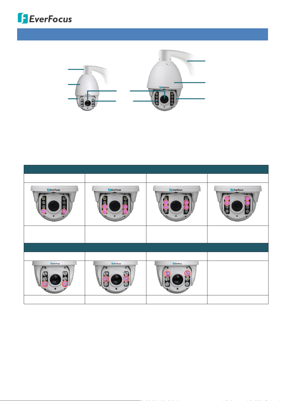
10x
(EPN5210)
30x
(EPN5230)
Bracket
Bracket
Camera Housing
Camera Housing
Camera Main Body
Camera Main Body
IR LEDs
Lens
EPN5230
1x Zoom
2x – 3x Zoom
4x – 9x Zoom
10x – 30x Zoom
2 Near-distance IR LEDs
2 Near-distance IR LEDs &
2 Middle-distance IR LEDs
4 Middle-distance IR LEDs
2 Middle-distance IR LEDs
& 2 Far-distance IR LEDs
EPN5210
1x – 2x Zoom
3x – 7x Zoom
8x – 10x Zoom
2 Near-distance IR LEDs
2 Middle-distance IR LEDs
2 Far-distance IR LEDs
2. Physical Description
Under Night or Auto Day Night mode, the camera will automatically switch the IR LEDs from the
near-distance lights to the far-distance lights based on the zoom ratio:
2
Page 9

EPN5230 / EPN5210
3. Features
Built-in 10x (EPN5210) / 30x (EPN5230) optical AF zoom
Dual streams from H.264
Easy and flexible installation
Built-in network interface (10 / 100 Base-TX)
True Day/Night function with removable IR cut filter
Extended IR range of up to 80m / 260ft. (EPN5210) ; 150m / 490ft. (EPN5230) with LEDs (Depending
on scene IR reflectivity)
Low luminance for better image quality at night
Motion Detection
Wide Dynamic Range (WDR)
Dynamic Noise Reduction (DNR)
From super slow to very fast pan / tilt speed
EPN5210: [0.1°/sec] to [240°/sec]
EPN5230: [0.1°/sec] to [180°/sec]
3D PTZ function
Weather proof IP66-rated
Maximum of 255 preset positions available
Programmable auto pan / 4 tours / 4 patterns
2 alarm inputs and 1 alarm output (EPN5230) / 1 alarm input and 1 alarm output (EPN5210)
Supports EverFocus’ CMS and mobile applications
ONVIF compliant
3
Page 10

EPN5230 / EPN5210
Note:
1. Equipment configurations and supplied accessories vary by country. Please consult your local
EverFocus office or agents for more information. Please also keep the shipping carton for possible
future use.
2. Contact the shipper if any items appear to have been damaged in the shipping process.
4. Installation
4.1 Packing List
Please check that there is no missing item in the package before installing.
IR network speed dome x 1
24VDC power supply x 1
Indoor Ceiling Pendant Mount / Enhanced Wall Mount Bracket Adapter (EPN5210 only, for
installing the optional brackets, see 4.2 Optional Accessory)
Hexagon Wrench x 1
Screws bag x 1 (which contains the below items)
EPN5210:
4 screws - for installing the optional Enhanced Wall Mount Bracket,
4 anchors - for installing the optional Enhanced Wall Mount Bracket,
3 hexagon socket screws - for attaching the speed dome to the Adapter,
3 socket set screws - for attaching the Adapter to the optional Enhanced Wall Mount Bracket,
1 DC power plug to 2-pin screw terminal.
EPN5230:
4 screws - for installing the Enhanced optional Enhanced Wall Mount Bracket,
4 anchors - for installing the Enhanced optional Enhanced Wall Mount Bracket,
4 washers - for installing the Enhanced optional Enhanced Wall Mount Bracket,
3 long socket set screws - for attaching the speed dome to the optional Enhanced Wall Mount
Bracket.
Glove x 1 pair
Desiccant pack:
EPN5210: 1 already placed inside the camera, with 1 spare part.
EPN5230: 2 already placed inside the camera, with 2 spare parts.
Software CD x 1
Mounting Template x 1
Quick Installation Guide x 1
4
Page 11
EPN5230 / EPN5210
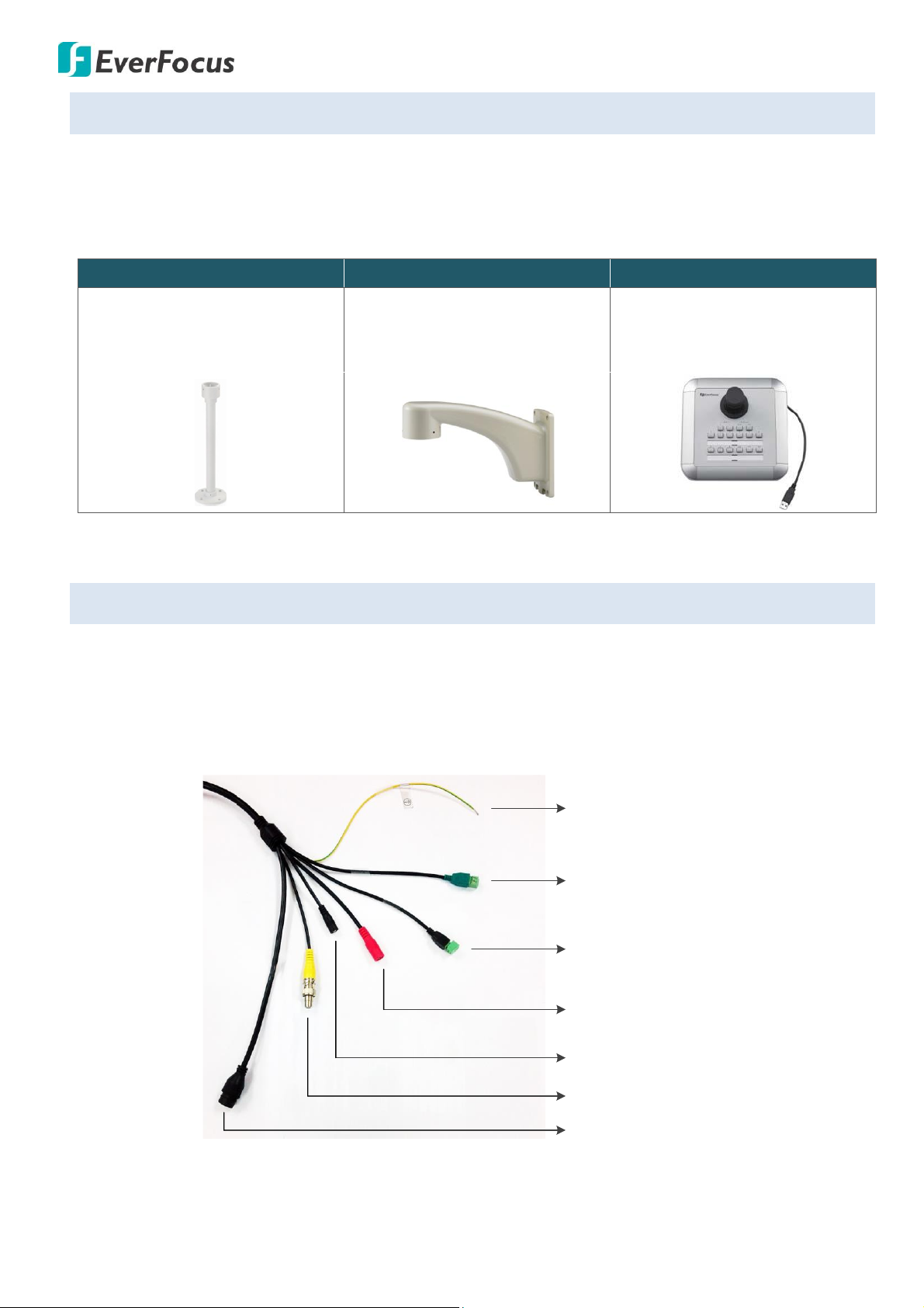
Indoor Ceiling Pendant Mount
Wall Mount
Keyboard
EPTZ-CLM
Indoor Ceiling Pendant Mount
Bracket
EPTZ-WMB
Enhanced Wall Mount Bracket
EKB200
USB controller keyboard
GND
Alarm Input (Green)
Alarm Output (Black)
Power Input
(24VDC / 24VAC~)
RJ45 / PoE
Reset Button
Audio In (Yellow)
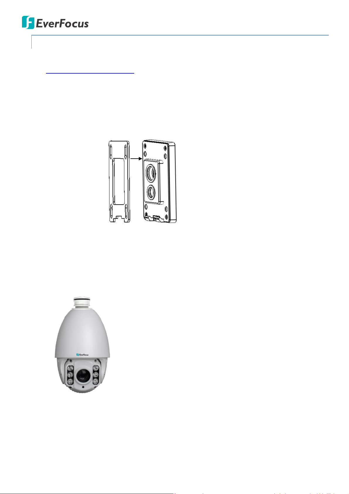
4.2 Optional Accessory
You can use the EPTZ-CLM Ceiling Pendant Mount Bracket or EPTZ-WMB Enhanced Wall Mount Bracket
to install the camera against the ceiling / wall. Please consult your local EverFocus office or agents for
more information.
4.3 Cable Descriptions
The cables include Audio In, Audio Out (EPN5230), Alarm I/O, Power, Network, Video Test-Out (EPN5230)
and Reset.
EPN5210
5
Page 12
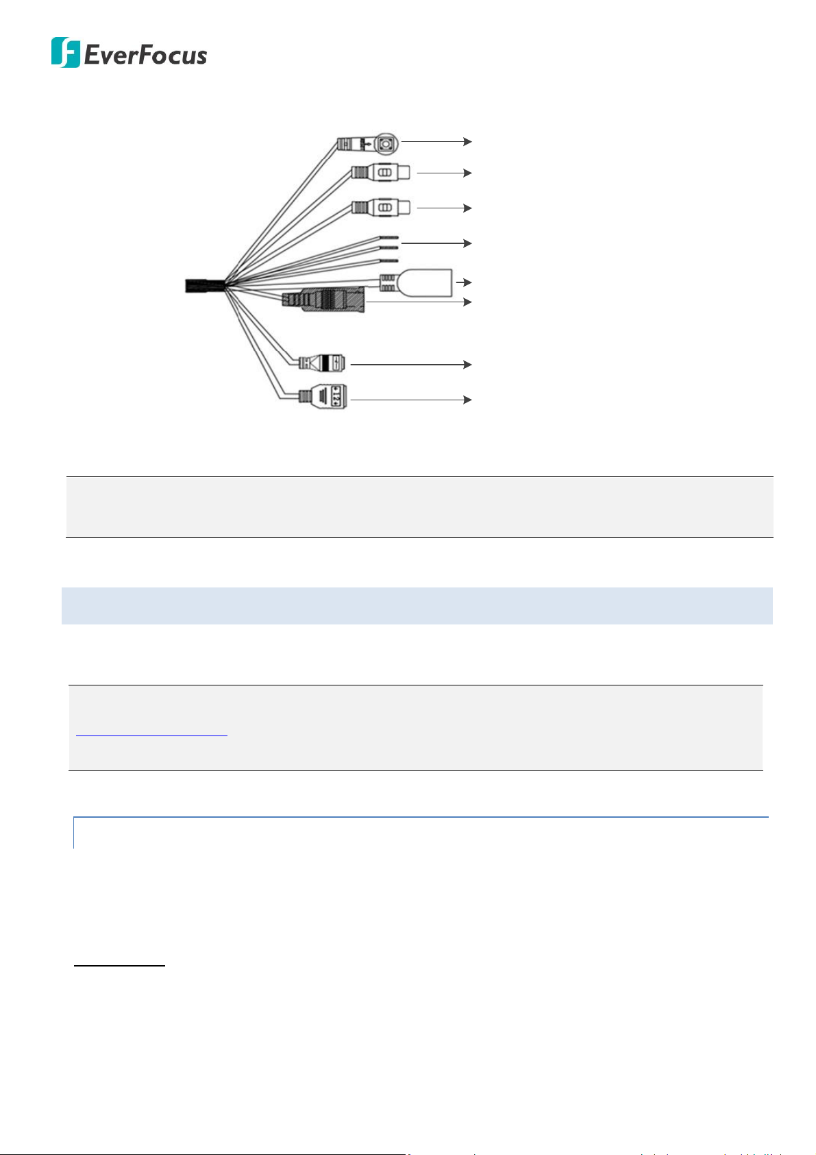
EPN5230
Alarm Input
Alarm Output
Video Test-Output
RJ45 / PoE
Audio Output (White)
Audio Input (Red)
Reset Button
Red Wire: 24VDC+
Black Wire: 24VDC-
Yellow Wire: GND
Note: If you use 24 VAC~ as the power input, please prepare a 24 VAC~ power supply to connect to the
power input cable.
Note: You can also install the camera against the ceiling using a ceiling pendant mount bracket (See
4.2 Optional Accessory). To acquire the ceiling pending mount bracket, please consult your local
EverFocus office or agents for more information.
EPN5230 / EPN5210
4.4 Basic Installation
A wall mount bracket is provided in the package. You can use the wall mount bracket to install the
camera against the wall.
4.4.1 Inserting a Micro SD Card
Before installing, insert a micro SD card into the camera module if you want to record the recordings to
the on-camera SD card.
For EPN5210:
1. To protect the camera lens from getting dirty and scraped up, please wear the supplied gloves
before installing the micro SD card.
6
Page 13

EPN5230 / EPN5210
Note: There is a desiccant bag placed inside the camera bottom module. The desiccant bag
loses its effectiveness after you open the camera. To keep the camera’s interior dry, it is
highly recommended to replace the desiccant bag every time when you open the camera.
2. Unscrew the four screws to remove the camera top module.
3. On the rear side of the camera top module, insert the micro SD card to the card slot.
4. This step is optional. If you want to replace a new desiccant bag, place the spare (or
self-prepared) desiccant bag in the same location as image below.
5. Screw back the camera top module.
7
Page 14
EPN5230 / EPN5210
For EPN5230:
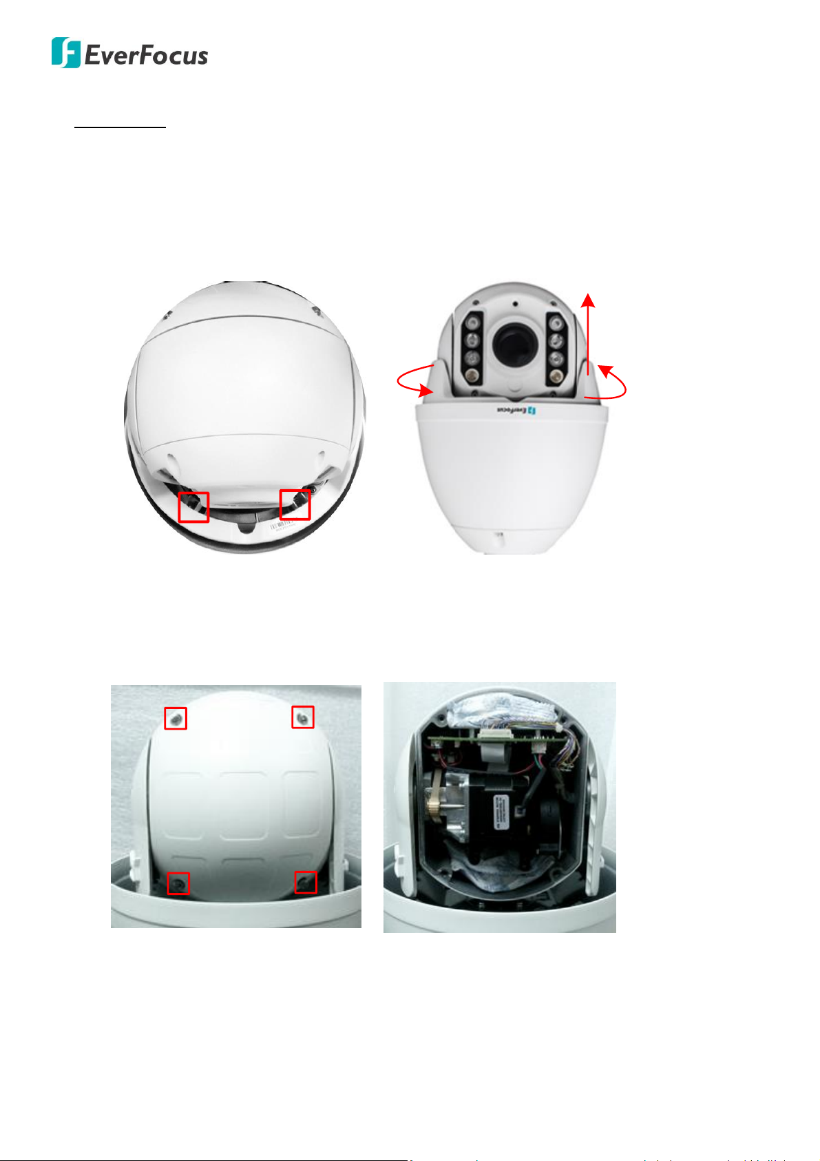
1. To protect the camera lens from getting dirty and scraped up, please wear the supplied gloves
before installing the micro SD card.
2. Unscrew the two screws inside the camera housing, twist the outer ring counterclockwise and
then lift up to remove the outer ring from the camera.
3. On the rear side of the camera, unscrew the four screws to remove the rear camera cover.
8
Page 15
EPN5230 / EPN5210
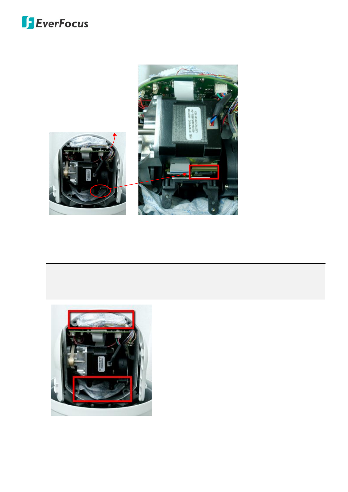
Push so you can see the
bottom of the camera module
Note: There are two desiccant bags placed inside the camera bottom module. The desiccant
bags lose their effectiveness after you open the camera. To keep the camera’s interior dry, it is
highly recommended to replace the desiccant bags every time when you open the camera.
4. Push the camera downward a little bit and you can see the micro SD card slot located on the
bottom of the camera module. Insert the micro SD card to the card slot.
5. This step is optional. If you want to replace new desiccant bags, place the spare (or self-prepared)
desiccant bags in the same location as image below.
6. Screw back the rear camera cover and the outer ring.
9
Page 16
EPN5230 / EPN5210
EPN5210
Waterproof
silicon pad
Bracket base plate
4.4.2 Wall-Mount Installation
1. Optionally insert a micro SD card or replace the desiccant bag(s) inside the camera module (see
4.4.1 Inserting a Micro SD Card).
2. Drill 4 screw-depth holes for mounting the bracket base plate and then drill a through-wall hole
for inserting the camera cables. You can optionally drill a second through-wall hole to separate
cable feeding.
3. Attach the waterproof silicon pad to the bracket base plate for waterproofing.
4. Optionally insert the supplied Anchors inside the holes on the wall.
5. To protect the camera lens from getting dirty and scraped up, please wear the supplied gloves
before screwing the camera to the Enhanced Wall Mount Bracket.
6. For EPN5210, screw the camera to the Adapter first using the supplied Hexagon Socket Screws.
10
Page 17
EPN5230 / EPN5210
WasherScrew
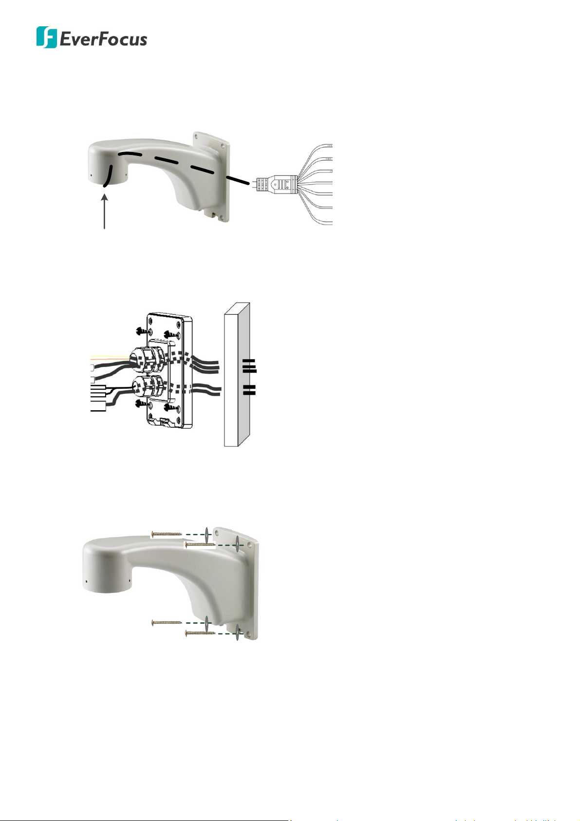
7. Feed the camera’s cables through the conduit in the Enhanced Wall Mount Bracket and then
through the wall.
8. Connect the camera’s cables to the related devices such as a speaker. Feed the cables of the
related devices through the wall and then through the holes of the bracket base plate.
9. Screw the Enhanced Wall mount bracket to the wall using the supplied Screws. For EPN5230, you
can place the supplied Washers between the Screws and the Enhanced Wall Mount Bracket.
10. Screw the camera to the Enhanced Wall mount bracket.
For EPN5210: Screw the camera with the Adapter to the Enhanced Wall Mount Bracket using the
supplied Socket Set Screws.
For EPN5230: Screw the camera to the Enhanced Wall Mount Bracket using the supplied Long
Socket Set Screws.
11
Page 18
EPN5230 / EPN5210
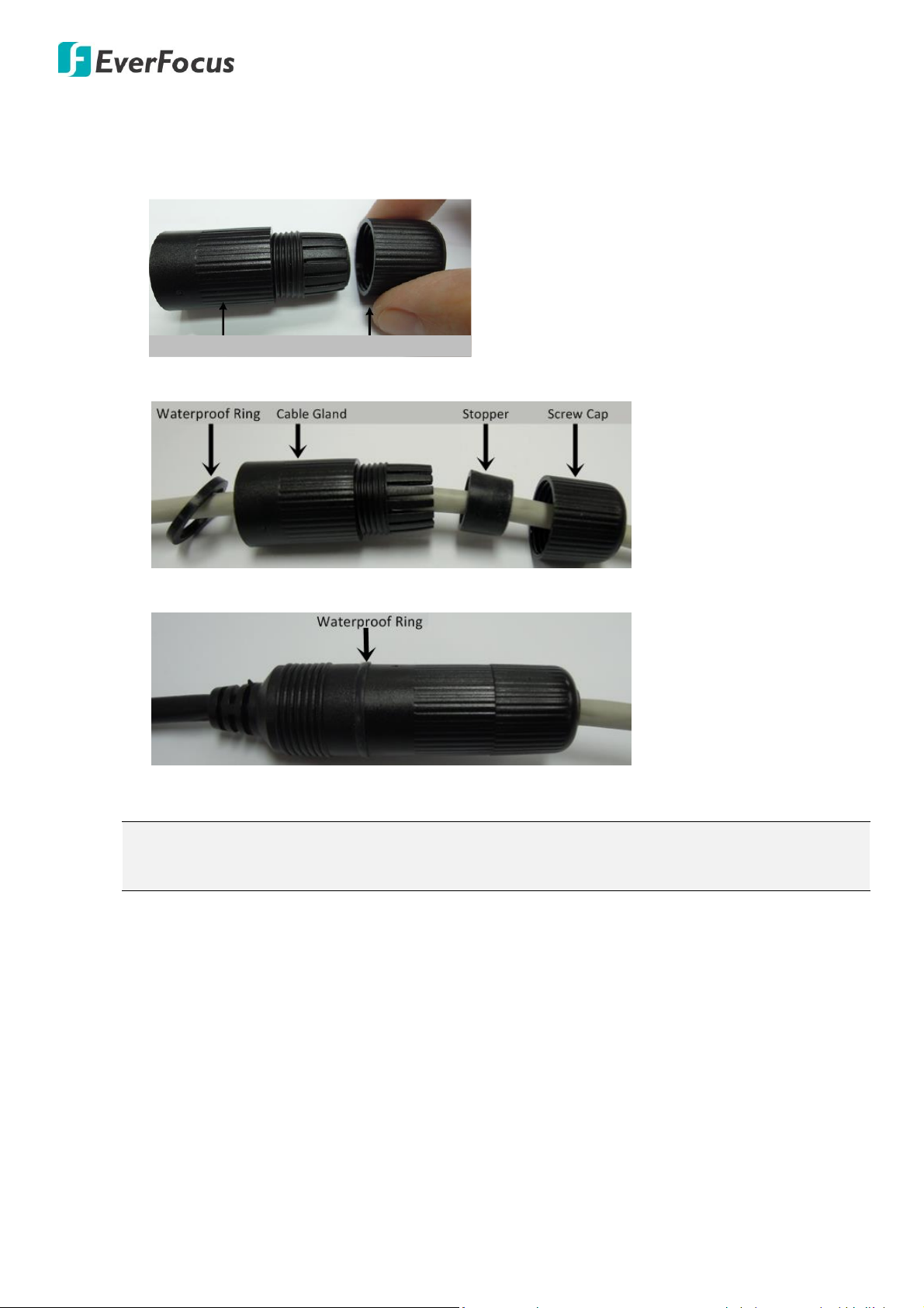
Cable Gland Screw Cap
Note: Depending on the camera model, speakers / microphones with a (built-in) amplifier and
external power supply may be required.
11. Connect the RJ45 / PoE cable to the camera.
a. Remove the Screw Cap from the Cable Gland.
b. Insert a RJ-45 network cable (without the RJ-45 connector on the one end) through the Cable
Gland and Screw Cap.
c. Place the Waterproof Ring into the LAN / PoE cable. Connect the RJ-45 cable to the RJ-45
Connector Cable. Tightly screw the Cable Gland and Screw Cap to the RJ-45 Connector Cable.
12. Connect the camera’s cables to the related devices such as a speaker or a power source.
12
Page 19
EPN5230 / EPN5210
5. Accessing the User Interface
This section explains how to access the Web interface of the camera for configuration.
5.1 Checking the Dynamic IP Address
You can look up the IP address and access the Web interface of the camera using the IP Utility (IPU)
software, which is included in the software CD or you can download it from EverFocus’ Website
http://www.everfocus.com.tw/HQ/Support/DownloadCenter_p1.aspx (Support > Download Center >
Keyword Search: IP Utility). Please connect the IP Camera in the same LAN of your computer.
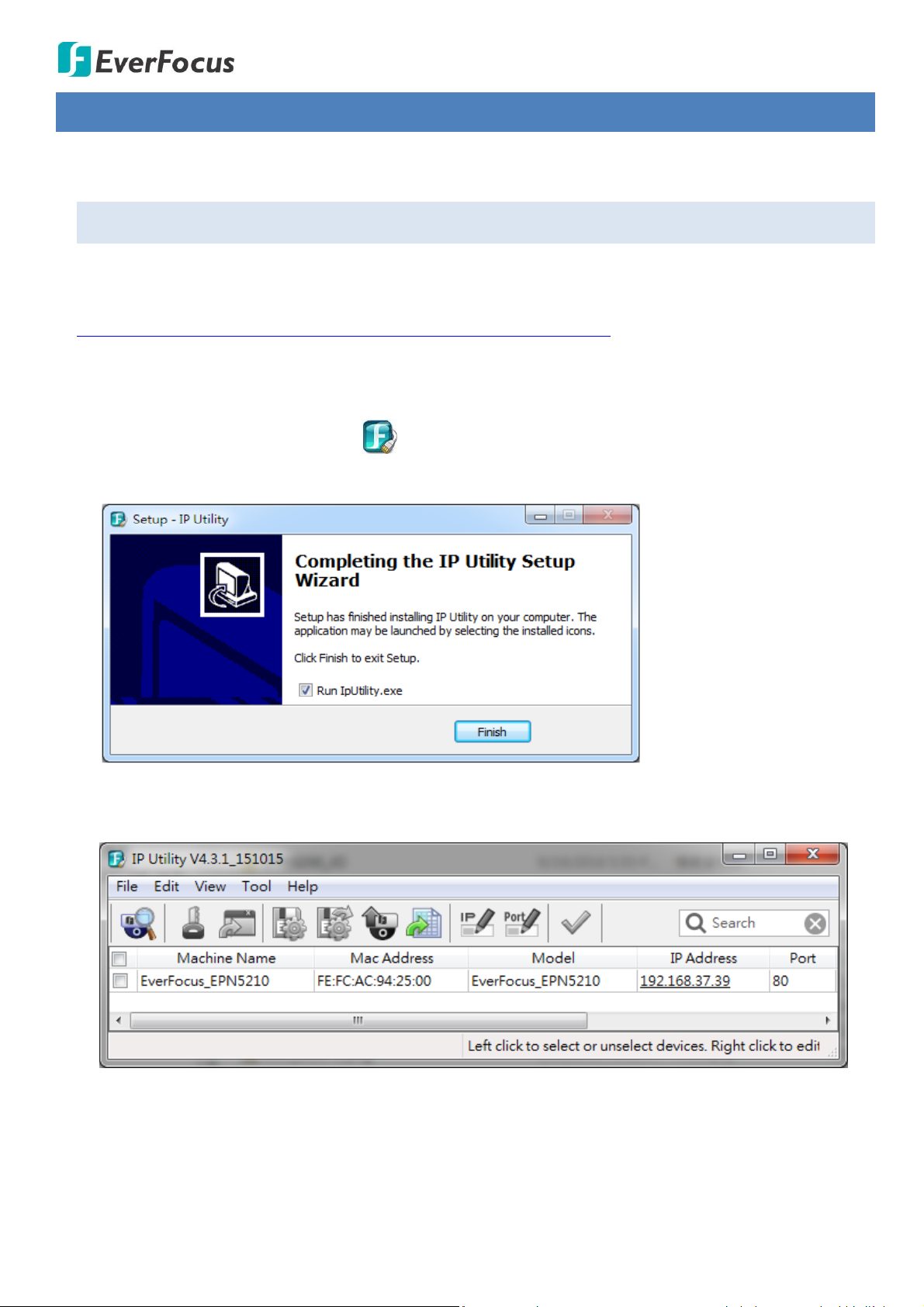
1. Save IP Utility Setup AutoRun.exe in your computer. Double click the .exe file and follow the
on‐screen instructions to install the IP Utility.
2. Check Run IPUtility.exe and click the Finish button, the IP Utility will be launched to search the IP
devices connected in the same LAN automatically.
13
Page 20
EPN5230 / EPN5210
Note:
1. To enable Remote Live View, Firmware Upgrade and ActiveX Prompt on Internet Explorer,
some settings have to be complete. Please refer to 5.2 Settings for Microsoft Internet Explorer
in the User’s Manual.
2. The default IP mode of the IP camera is DHCP. However, if there is no dynamic IP address
assigned to the device, its IP will switch to 192.168.0.10.
3. To access to the Live View window, double-click the IP address of the device, the login window
appears.
4. Download and install the ActiveX file by clicking EverFocus on the login window. Click Run and follow
the instructions to install the program. Click Finish to complete the process.
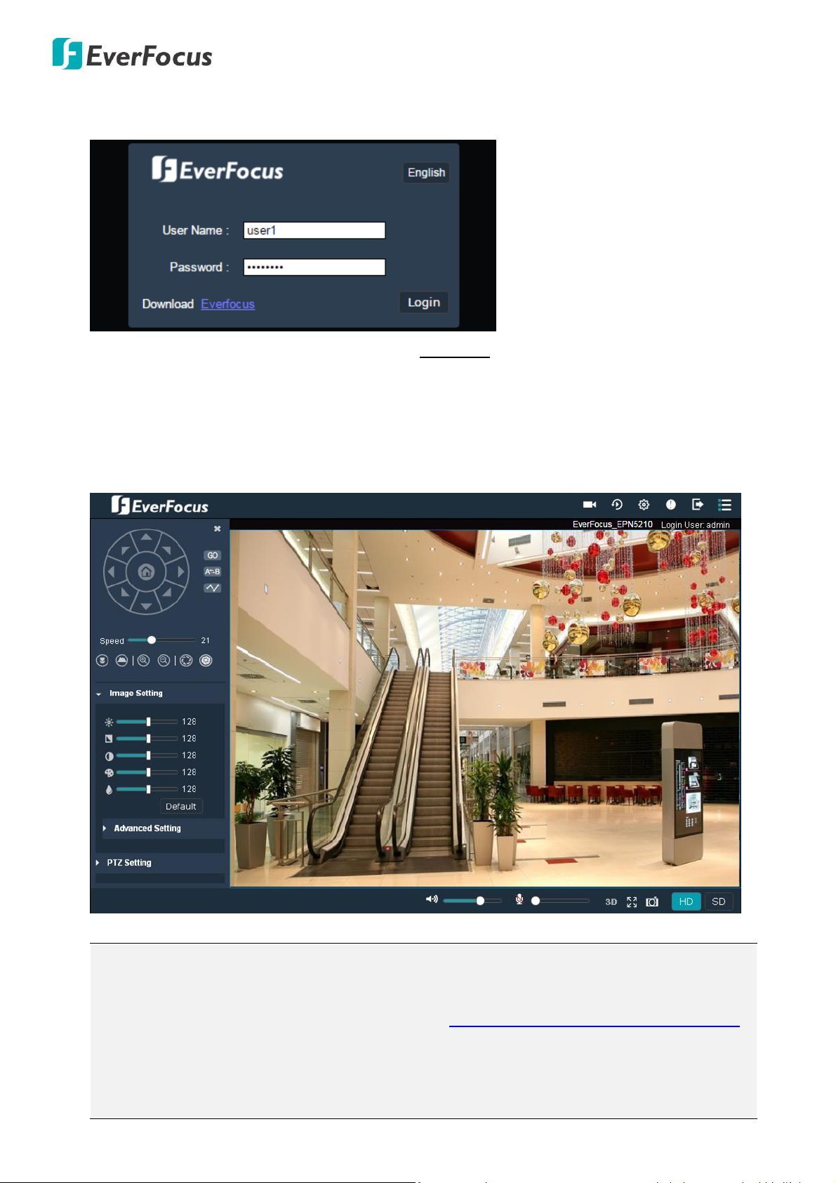
5. Select a desired language by clicking the language button on the top-right corner of the login
window.
6. Type the user name and password on the login window. By default, the user ID is user1 and the
password is 11111111. Click Login, the live view window appears.
14
Page 21
EPN5230 / EPN5210
5.2 Settings for Microsoft Internet Explorer
To enable Remove Live View, Firmware Upgrade and ActiveX Prompt on Internet Explorer, some
settings have to be complete. Please follow the steps below:
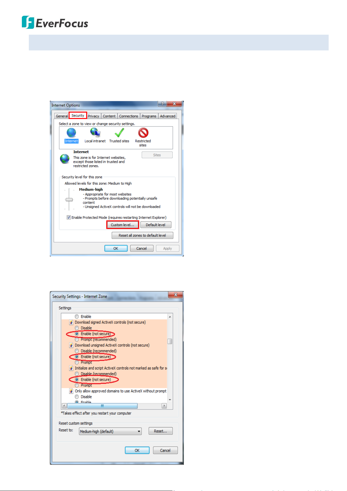
1. Open the Internet Explore, click Tools > Internet Options > Security Tab > Custom Level, the
Security Settings windows appears.
2. In the Download signed ActiveX controls field, select Enable. In the Download unsigned ActiveX
controls field, select Enable. In the Initialize and script ActiveX controls not marked as safe for
scripting field, select Enable. Click OK.
15
Page 22
EPN5230 / EPN5210
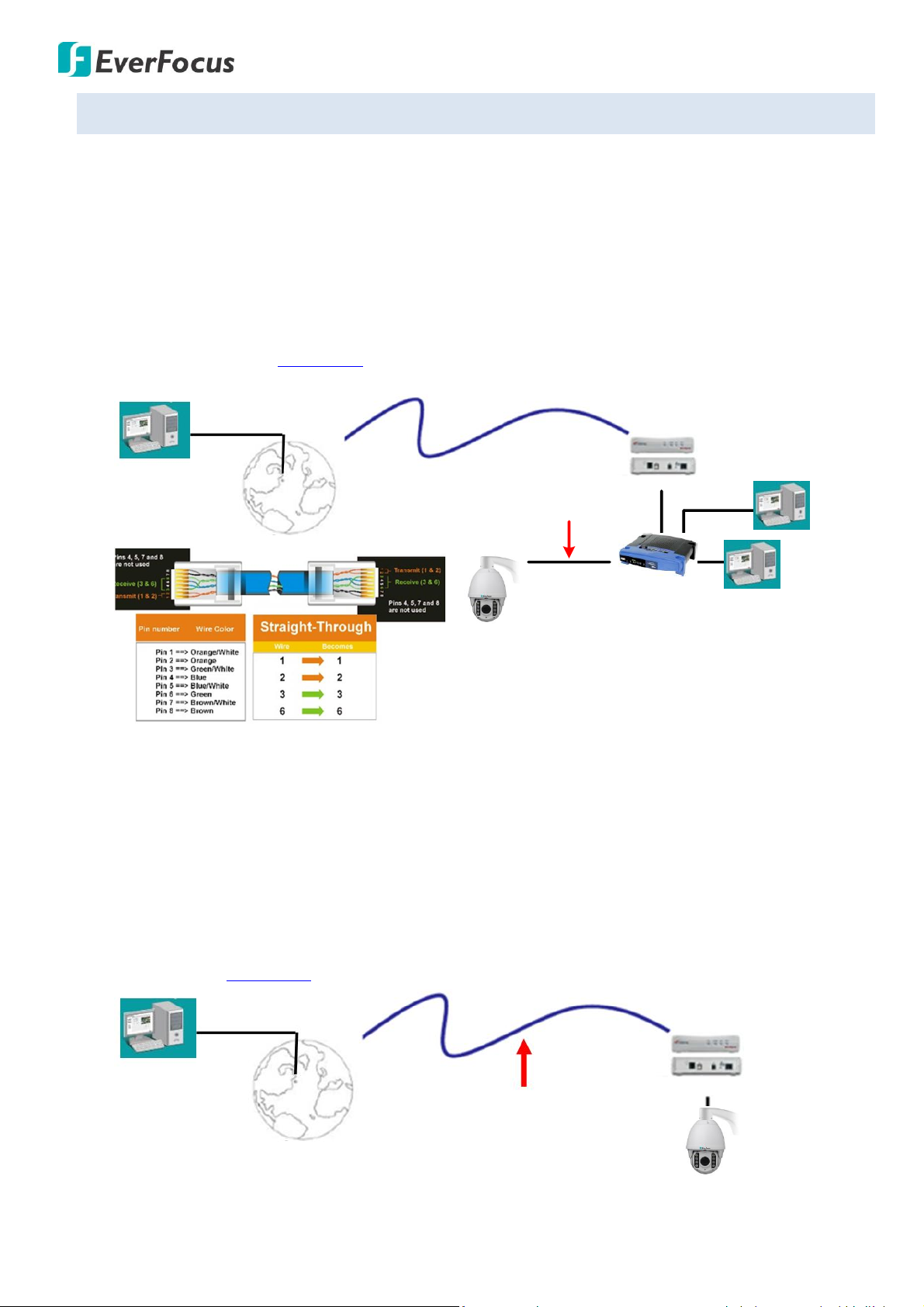
High-speed modem
Internet
Straight-through LAN patch cable
Router
Cat 5 Straight Through Cable
Left: Pinout of a straight-through cable.
Cat 5
Straight Through Cable
High-speed modem
Internet
5.3 Connecting the Camera to the Network
There are three methods to connect the IP camera to the network: Router or LAN Connection, Direct
High-Speed Connection and One-to-One Connection.
Router or LAN connection
This is the most common connection in which the IP camera is connected to a router and allows
multiple users on and off site to see the IP camera on a LAN/WAN (Internet). The camera must be
assigned an IP address that is compatible with its LAN. To remotely access the Web interface of the IP
camera, please refer to 7.3.2 DDNS.
Direct High-Speed Connection
In a Direct High-Speed Connection, the camera connects directly to a modem without the need for
a router. You need to set the static or dynamic WAN IP address assigned by your ISP (Internet
Service Provider) in the camera’s configuration web pages. To access the camera, just type
“http://xxx.xxx.xxx.xxx”, where xxx.xxx.xxx.xxx is the IP address given by your ISP. If you have a
dynamic IP address, this connection may require that you use DDNS for a reliable connection.
Please refer to 7.3.2 DDNS.
16
Page 23

EPN5230 / EPN5210
Cat 5
Right: Pinout of a crossed-over cable.
One-to-One Connection (Directly from PC to IP Camera)
You can connect directly without using a switch, router or modem. However, only the PC connected
to the camera will be able to view the IP camera. You will also have to manually assign a compatible
IP address to both the computer and the IP camera. Unless the PC has another network connection,
the IP camera will be the only network device visible to the PC. See the diagram below:
17
Page 24

EPN5230 / EPN5210
7
8
9
10
12 13 14 1715 16
1 2 3 4 5 6
11 18
No
Name
Description
1
Record
Click to start the manual recording to your computer in MP4 format. Click
again to stop recording. By default, the recording path is at
C:\Everfocus\EPN5xxx (where 5xxx is the model name). To change the
storage path, go to Setting > Local > Local (see 7.5.1 Local). You can play
back the recordings using any MP4 players or use the built-in player
through the UI interface (see 6. Playback for more details).
2
Playback
Click to enter the Playback page for playing back the recordings from the
camera or from the local computer. Please refer to 6. Playback.
3
Setting
Click to enter the Setting page for camera configurations. Please refer to 7.
Setting for more details.
5.4 Live View Window
18
Page 25

EPN5230 / EPN5210
4
Event
Click to view the live event list.
To set up the event configurations, please refer to 7.4 Alarm.
5
Exit
Click to log out of the Web interface.
6
Toggle Menu
Click to toggle the Menu bar to the left or right. Click the X button on the
top-left / top-right corner can close the Menu bar. To bring up the Menu
bar, click the Toggle Menu button again.
7
PTZ Control Panel
You can operate the PTZ directions, preset, AB tour or pattern functions
using the PTZ Control Panel. Use the slider to adjust the speed for Pan and
Tilt.
After configuring the related settings in the PTZ Setting field (see 5.4.2 PTZ
Setting), you can use the quick buttons including (Quick Preset),
(Quick Auto Pan) and (Quick Tour) to activate the functions easily
and quickly.
Click the button to perform / stop endless 360°pan.
8
Focus / Zoom / Iris
Control
Use the buttons to adjust Focus near / far, buttons to
adjust Zoom in / out, and buttons to adjust Iris open / close.
9
Image Setting
Click to expand or collapse the Image Setting field. You can adjust basic
image parameters in this field. See 5.4.1 Image Setting for more details.
10
PTZ Setting
Click to expand or collapse the PTZ Setting field. You can set up the Preset
positions, AB Pan, Tour or Pattern functions in this field. See 5.4.2 PTZ
Setting for more details.
19
Page 26

EPN5230 / EPN5210
11
Live Stream
Live stream displays the live stream from the camera. You can also operate
the up / down / left / right directions by moving your mouse cursor over
the image, when the direction buttons appear, click on the image to force
the camera move toward the direction.
12
Speaker
(Only for EPN5230)
Slide the bar to adjust the speaker volume. Note for this function to work,
speakers with a (built-in) amplifier and external power supply are required.
13
Microphone
Slide the bar to adjust the microphone volume. Note for this function to
work, microphones with a (built-in) amplifier and external power supply
are required.
14
3D PTZ
Click to enter the 3D PTZ mode. In the 3D PTZ mode, you can zoom in/out a
specific area or move to a desired position simply by clicking the mouse.
To zoom in/out a specific portion of the Live View Window:
Click and drag downward on the Live View Window to select an area to
zoom in; click and drag upward on the Live View Window to select an area
to zoom out. The smaller the area, the further it will be Zoomed In/Out.
Zoom In
20
Page 27

EPN5230 / EPN5210
14
3D PTZ
To move to a position on the Live View Window:
Click on the Live View Window to force the camera move to the desired
position. The point you clicked will be displayed in the center of the
window.
Click again to exit the 3D PTZ mode.
15
Full Screen
Click to display the camera stream in full screen. To exit full screen,
right-click the mouse and click Exit or press the ESC button on keyboard.
16
Snapshot
Click to take a snapshot of the current live stream. By default, the
snapshots will be stored in C:\Everfocus\EPN5xxx (where 5xxx is the model
name). To change the storage path, go to Setting > Local > Local (see 7.5.1
Local).
17
HD
Click to display the live stream in Main stream. To set up the main stream,
go to Setting > Video > Video Stream (see 7.2.1 Video Stream).
18
SD
Click to display the live stream in Sub stream. To set up the sub stream, go
to Setting > Video > Video Stream (see 7.2.1 Video Stream).
21
Page 28

EPN5230 / EPN5210
Brightness
Hue
Contrast
Saturation
Sharpness
Click to return the above value to factory default
Click to expand the Advanced Setting field
Flip Image: Click the buttons to flip the image horizontally or
vertically.
BLC: Check/uncheck the box to enable/disable the Backlight Compensation
function.
Low Lux: Check/uncheck the box to enable/disable the low lux function.
WDR: Check/uncheck the box to enable/disable the Wide Dynamic Range
function.
3D DNR: Check/uncheck the box to enable/disable the 3D Digital Noise
Reduction function.
Day Night Mode: Click to switch the camera to day mode. Click to
switch the camera to night mode. Click for the camera to switch
between day and night modes automatically. If Auto is selected, you can
configure the sensitivity ranging from 0-255 in the To Mono and To Color
field. So the camera will automatically switch between day mode and night
mode based on the setup sensitivity.
Under Night or Auto Day Night mode, the camera will automatically switch
the IR LEDs from the near-distance lights to the far-distance lights based on
the zoom ratio. Please refer to 2. Physical Description for more details.
5.4.1 Image Setting
On the Live View Window, click Image Setting to expand the image setting field. You can adjust image
parameters including brightness, hue, contrast, saturation and sharpness in this field. To restore the
parameters to default value, click the Default button. To collapse the Image Setting field, click Image
Setting again.
To further configure the image parameters, click Advanced Setting to expand the Advanced Setting field.
Click Advance Setting again can collapse the setting field.
22
Page 29

EPN5230 / EPN5210
AWB Mode: Auto White Balance mode. Select an item from the drop-down
list and then click the Save button to save the settings. For Customized, you
can further configure the R (Red), G (Green) and B (Blue) values yourself in
the fields above this field.
Video Formats: Select a video format. 50Hz for PAL and 60Hz for NTSC. Click
the Save button to save the settings.
EV Level: Select an exposure level from the drop-down list and then click the
Save button to save the settings.
Exposure Mode: Select Auto or Manual from the drop-down list and then
click the Save button to save the settings.
For Auto Exposure mode, you can further configure the Max Shutter, Min
Shutter and Max Gain values yourself in the fields below this field.
Max Shutter: Select a max. shutter value from the drop-down list and then
click the Save button to save the settings.
Min Shutter: Select a min. shutter value from the drop-down list and then
click the Save button to save the settings.
Max Gain: Select a gain value from the drop-down list and then click the
Save button to save the settings.
For Manual Exposure mode, you can further configure the Shutter and Gain
values yourself in the fields below this field.
Shutter: Select a shutter value from the drop-down list.
Gain: Select a gain value from the drop-down list.
Save: Click to save the settings.
23
Page 30

EPN5230 / EPN5210
Auto Pan: To set up the Auto Pan function, use the direction buttons
on the PTZ Control panel to direct the camera to a desired left
position and then click to set up the left position; find a desired
right position and then click to set up the right position. When
setting up the left or right position, you have to select Narrow radian
scan from the drop-down box to scan area less than 180° or Wide
radian scan to scan area more than 180°.
To activate the Auto Pan function, click the Invoke button . You
can also use the Quick Auto Pan button on the right side of the
PTZ Control Panel to quickly activate the Auto Pan function. To stop
the Auto Pan function, click any directions on the PTZ Control Panel
or on the Live Stream.
PTZ Watch: You can set up an idle time for the camera. When the
camera idles (no action) over the setup time, the related function
such as preset or pattern will be activated. To set up the PTZ Watch
function, input an idle time, select a function from the drop-down. If
Preset, Tour, or Pattern is selected, select a number from the number
drop-down. Click the Save button to save the settings and the setup
PTZ Watch function will be activated. To turn off the PTZ Watch
function, select Close from the function drop-down.
Preset: You can set up a max. of 255 preset positions. To set up a
preset position, select a preset number from the number drop-down,
adjust the camera view to a desired position using the
direction/zoom/iris/focus buttons on the PTZ Control panel, click the
Save button to save the settings. To activate the Preset function,
select a preset number from the number drop-down and then click
the Invoke button . You can also use the Quick Preset button
on the right side of the PTZ Control Panel to quickly activate the
Preset function.
5.4.2 PTZ Setting
On the Live View Window, click PTZ Setting to expand the PTZ setting field. You can set up Auto Pan,
PTZ Watch, Preset Positions, Pattern and Tour functions in this field. To collapse the PTZ Setting field,
click PTZ Setting again.
Pattern: You can record the camera movement in a period of time as a pattern, and then force the
camera to move as the set up pattern repeatedly. Up to four Pattern sequences can be set up. To set up
a Pattern sequence, select a number from the number drop-down, optionally input a name for this
patter sequence in the blank column, and then click the Start recording button to start recording
24
Page 31

EPN5230 / EPN5210
Tour: You can combine multiple preconfigured preset positions into one long
sequence. Up to four Tour sequences can be set up. To set up a Tour
sequence, select a tour number from the number drop-down, click the +
button and a Message window pops up. Select the desired preset number,
and then input a dwell time in the Delay Time column for the camera to
pause at a preset position. Click the Add button, this preset number will be
displayed in the Tour table below the Tour field. Repeat this step to add as
many preset numbers as desired. To delete a preset number from the Tour
table, click to select a preset number from the Tour table and then click the
X button. After configuration, click the Save button to save the setting. To
activate the Tour function, select a tour number from the number
drop-down and then click the Invoke button . You can also use the Quick
Tour button on the right side of the PTZ Control Panel to quickly
activate the Tour function.
pattern scan. During the period of scanning, you can use the direction/zoom/iris/focus buttons on the
PTZ Control panel to move the camera to different positions. Click the Stop recording button to
stop recording pattern scan. To activate the Pattern function, select a number from the number
drop-down and then click the Invoke button .
25
Page 32

EPN5230 / EPN5210
6. Playback
You can remotely play back the recordings stored in the on-camera micro SD card on the Web interface,
or play back the recordings stored in the computer using any MP4 players.
6.1 Remote Playback Using Playback Page
On the Live View Window, click the Playback button to enter the Playback page.
To search and then play back the recordings:
1. Click on the Start/End column to bring up the calendar and then select a start/end date. Key in the
desired time for the date.
2. Select a source of recordings from the Record Type drop-down list.
Local Record: Search for recordings stored in the computer (C:\\Everfocus\EPN5xxx).
Device Record: Search for the recordings stored in the on-camera micro SD card.
3. Click the Search button , the searched results will be displayed in the below column.
4. Double-click a recording in the column, and the selected recording will be played back on the
screen.
26
Page 33

EPN5230 / EPN5210
Note: The Device Record function is only functional once the on-camera micro SD card is inserted and
activated.
EPN5230
EPN5210
5. To pause playback, click the pause button . To switch the playback speed between 1X to 32X,
click the fast-forward button .
To directly load the recording files stored in the computer for playing back:
1. Click the Open File button to load the recordings stored in the computer. And the selected
recording will be played back directly on the screen.
2. To pause playback, click the pause button . To switch the playback speed between 1X to 32X,
click the fast-forward button .
Click the Live Video button can go back to the Live View Window. Click the Exit button can
exit the Web interface.
27
Page 34

EPN5230 / EPN5210
7. Setting
You can configure the system settings on this page. On the Live View Window, click the Setting
button to enter the setting page, and a menu bar appears on the left side of the window. Enter each field
to configure the settings.
Click the Live Video button can go back to the Live View Window. Click the Exit button can exit
the Web interface.
28
Page 35

EPN5230 / EPN5210
7.1 System
You can configure basic system settings such as System Info, User Management, Schedule PTZ Task /
Record, Time Zone and SD Card Status on this page. Click the tab of the one you want to see.
7.1.1. Basic Info
You can check system information and system log. Also you can reset, reboot the camera and upgrade
firmware.
7.1.1.1. System Info
You can set up the device name and check system information using this page.
Device Name: If required, enter a new name for the device. This name will be visible in the Live
View Window. Click the Save button on the bottom-right to save the settings.
FW Version: The value of firmware version cannot be changed on this page, and are for reference
only.
MAC: The value of MAC address cannot be changed on this page, and are for reference only.
29
Page 36

EPN5230 / EPN5210
7.1.1.2. System Maintenance
You can reset or reboot the IP camera, and load or save parameters using this page.
Reset: Click this button to restart and reset the current settings to their factory default values.
Reboot: Click this button to reboot the unit without changing any of the settings. Use this function
if the unit is not behaving as expected.
To import parameters:
Press the Browse button to load a previously saved parameter (“.log”) file and then click the
Parameter import button. The system’s settings will be restored to the saved configuration.
Please be noted that importing a new parameter file will cause the system to reboot
automatically.
To export parameters:
To make a backup file of the machine’s current parameters, check the box to select the desired
parameter types and then press the Parameter export to save all the configurations to a “.log”
file.
Click the Save button on the bottom-right to save the settings.
30
Page 37

EPN5230 / EPN5210
7.1.1.3. FW Upgrade
You can upgrade firmware using this page.
Click the Scan button to select a previously prepared firmware file. Click OK to install the new
firmware. Please be noted that you may need to restart the browser after upgrading firmware.
Click the Save button on the bottom-right to save the settings.
7.1.1.4. Log
You can search the log events by date, time and type, or export system log using this page.
31
Page 38

EPN5230 / EPN5210
To search the system log:
1. Click on the Type drop-down list to select a log type from All, Alarm, Exception, Operation and
Information.
2. Click on the Start/End Time column to bring up the calendar and then select a start/end date
and time.
3. Click the Query button, the search result will be displayed in the below column.
To export the system log:
Click the Export button to export the system log list into a “.txt” file.
32
Page 39

EPN5230 / EPN5210
7.1.2. User Management
The system administrator can create user accounts on this page.
To add a user account:
1. Click the Add User button and the following dialog box appears.
2. Type the user name and password for the account.
3. Select an authority level for the user account from the User Group drop-down list.
Admin: Admin Account can edit all accounts and their password.
Operate / User: Operate / User Account can only edit their own login account and password.
(Multiple Admin / Operate / User Account can be configured.)
4. Click Add to add the user account. Repeat this step to add as many user accounts as desired.
5. Click the Save button on the bottom-right to save the settings.
33
Page 40

EPN5230 / EPN5210
To modify a user account:
1. Highlight a user account and click the Modify button. The following dialog box appears.
2. Type the user name and password for the account. Type the password again in the Confirm
password field.
3. Click Modify to save all the settings.
4. Click the Save button on the bottom-right to save the settings.
To delete a user account:
1. Highlight a user account and click the Delete User button. The following dialog box appears.
2. Click OK to delete the user account.
3. Click the Save button on the bottom-right to save the settings.
34
Page 41

EPN5230 / EPN5210
7.1.3. PTZ Setting
You can set up the serial communication, or schedule PTZ tasks for each day.
7.1.3.1. Serial Setting
Use this page to configure the serial communication parameters.
Address: select the camera’s address.
Baud Rate: select the camera’s baud rate (transmission speed).
Protocol: select the communication protocol.
Click the Save button on the bottom-right to save the settings.
7.1.3.2. Schedule Task
Use this page to configure a schedule for performing Preset / Tour / Pattern / Area during the
specified day and time.
To add a schedule PTZ task:
1. Check the Enable box to enable the Schedule Task function.
2. Set up the interval between the tasks, from 5 to 3600 seconds, in the Task Restart field.
35
Page 42

EPN5230 / EPN5210
3. Select a day (Sunday ~ Saturday) from the Day drop-down list to apply the schedule.
4. Click the Add Task button and select a Start/End time.
5. Select a Task Mode. For Preset, Tour and Pattern, specify a Task Mode Number.
6. Click the Save button on the bottom-right to save the settings.
You can also use the Copy To function to copy the PTZ schedule of current day to the other day.
For example, if you want to copy the PTZ schedule of Tuesday to Wednesday and Thursday:
1. Select Tuesday from the Day drop-down list, and then click Copy To.
2. On the following dialog box, check to select Wednesday and Thursday. Click OK to save the
settings.
To delete a PTZ schedule, click a PTZ schedule and click the Delete Task button.
36
Page 43

EPN5230 / EPN5210
7.1.4. Record
You can set up recording schedules for each day, or set up schedules for uploading records / snapshots
to the FTP server.
7.1.4.1. Schedule Record
Use this page to configure a schedule for recording to the on-camera SD card during the specified
day and time.
To add a schedule recording task:
1. Check the Enable box to enable the Schedule Record function.
2. Select On / Off in the Overwrite field to overwrite recording file / stop recording when the
disk storage capacity is full.
3. You can limit the size of each recorded file, from 1 to 15 minute(s), in the File Size field. Once
you click the Record button on the Live View window, the camera will start recording the live
stream to your computer. When a single recording file exceeds the time you set, the system
will create a new file to save that data to.
4. Select a day (Sunday ~ Saturday) from the Day drop-down list to configure the schedule.
5. Click the Add Task button and select a Start/End time.
6. Click the Save button on the bottom-right to save the settings.
You can also use the Copy To function to copy the record schedule of current day to the other day.
For example, if you want to copy the record schedule of Tuesday to Wednesday and Thursday:
1. Select Tuesday from the Day drop-down list, and then click Copy To.
37
Page 44

EPN5230 / EPN5210
Note: If there is no snapshot or record file in the selected Start/End time, system will not upload
any file to the FTP server.
2. On the following dialog box, check to select Wednesday and Thursday. Click OK to save the
settings.
To delete a record schedule, click a record schedule and click the Delete Task button.
7.1.4.2. Update Schedule to FTP
Use this page to configure a schedule for uploading records / snapshots to the FTP server.
To add a schedule to upload snapshot or record files to the FTP server:
1. Click on the Start/End column to bring up the calendar and then select a start/end date.
2. Select to upload snapshot or record in the File Type field.
3. Click the FTP Upload button to upload snapshot or record files within the start / end time to
the FTP server. To change the FTP setting, see 7.3.3. Port Setting.
4. Click the Save button on the bottom-right to save the settings.
38
Page 45

EPN5230 / EPN5210
7.1.5. Time Zone
Use this page to set up Time and Daylight Saving.
【Time Setting】
Date-Time: Set the date/time here if you won’t be using an NTP server to update the date/time (see
below). Check the Synchronize PC Time box and the camera’s time will be automatically adjusted by
synchronizing with the PC Time.
Time Zone: Set the time zone of the camera’s location.
NTP Server: Enter the Network Time Protocol server, if applicable. The camera’s time will be
automatically adjusted by synchronizing with the NTP server. Check the Auto connect to service box
and the camera’s time will be automatically adjusted by synchronizing with the NTP Server.
【Daylight Saving Time】
Enable: Check the box to enable the Daylight Saving Time function.
Start/End Time: Select the dates when the region’s daylight saving period begins and ends.
Offset Time: Set up the summer offset time, if applicable.
39
Page 46

EPN5230 / EPN5210
7.1.6. SD Card Status
You can check the SD Card utility or format the SD Card using this page.
【SD Card Status】
SD Card Usage: This shows you the memory capacity of the card and how much card memory has been
used.
Format: Click this button to format the card. All data saved on the SD card will be removed if the card
is formatted.
40
Page 47

EPN5230 / EPN5210
Note: If you connect to the camera via the Internet and experience a delay (lag time) in the video
feed, try to reduce the quality and resolution of the streams – but keep the frame rate at its
maximum.
7.2 Video
You can configure settings relating to video such as streaming, camera OSD, Privacy Mask, Focus /
Zoom and Image on this page. Click the tab of the one you want to see.
7.2.1. Video Stream
This IP camera can output two video streams simultaneously. For each of these streams, you can set
the resolution, frame rate, quality, profile, GOP, rate control and video codec individually.
Resolution: Select the most suitable resolution for your needs.
Frame Rate: Enter the desired frame rate, from 1 to 30 fps.
Quality: Enter the desired front end devices video coding quality, from 1 to 100.
Profile: Select the video coding level from High, Base or Main.
GOP: Enter the GOP (Group of pictures) value, from 1 to 50.
Rate Control: If required, select whether you want the stream to stream a CBR (Constant Bit Rate) or a
VBR (Variable Bit Rate), and set the values of whichever option you choose.
Video Codec: Select the video compression format. The camera currently only supports H.264.
Click the Save button on the bottom-right to save the settings.
41
Page 48

EPN5230 / EPN5210
7.2.2. OSD Overlay
You can set up the information to be displayed on the Live View Window using this page.
Font size: Select the font size of displayed information.
BPS: Check the box to display BPS information (Frame Rate & Bit Rate).
Time: Check the box to display time information. Select a time format from the drop-down list. To
change the day and time setting, see 7.1.5. Time Zone.
Name: Enter the desired channel name in the input field, and check the box to display the name.
Text1 ~ Text5: Enter the desired text in the input field, and check the box to display the text.
The selected information will be displayed on the Live View Window, live view video images and
snapshots. To relocate the text, simply drag the text on the preview window to the desired position.
Click the Save button on the bottom-right to save the settings.
42
Page 49

EPN5230 / EPN5210
7.2.3. Privacy Mask
The Privacy Mask can block out sensitive areas from view, covering the area with black box in both live
view and recorded clips. This feature is useful when users’ don’t want the sensitive information visible.
To set up a Privacy Mask:
Check the Enable box to enable the Privacy Mask function. On the preview window, click and drag to
draw the desired Privacy Mask area, the area will be marked in purple.
You can also operate the up / down / left / right directions of the preview window by the
buttons, or adjust zoom in / out of the preview window using the
buttons.
You can remove the configured Privacy Mask by clicking the Clear All button. Click the Save button on
the bottom-right to save the settings.
43
Page 50

EPN5230 / EPN5210
7.2.4. Focus / Zoom Setting
You can configure Auto Focus and Digital Zoom setting using this page.
AF Control Mode: Select a focus mode from Auto, Semi-automatic or Manual. For “Semi-automatic”
and “Manual”, use the Focus+ Focus- Zoom+ Zoom- buttons on the Live View
Window to adjust focus / zoom.
AF Sensitivity: Enter the AF sensitivity value, from 1 to 255.
AF Area Select: Select the Auto Focus area from All Region Focus or Center Focus.
AF Search Mode: Select the Auto Focus search mode from Full View, 1.5m, 3m, 6m or Infinity.
Iris Control: Select an iris mode from Auto or Manual. For “Manual”, use the Iris+ Iris-
buttons on the Live View Window to adjust iris.
Digital Zoom: Check the box to enable the Digital Zoom function.
Click the Save button on the bottom-right to save the settings.
44
Page 51

EPN5230 / EPN5210
7.2.5. Image Setting
You can configure the image parameters using this page, or using the Advanced Setting field on the
Live View Window.
To Mono / To Color: You can configure the sensitivity for Auto Day Night Mode ranging from 0-255 in
the To Mono and To Color field. So the camera will automatically switch between day mode and night
mode based on the setup sensitivity.
AWB Mode: Auto White Balance mode. Select an item from the drop-down list. For Customized, you
can further configure the R (Red), G (Green) and B (Blue) values yourself in the fields above this field.
Video Format: Select a video format. 50Hz for PAL and 60Hz for NTSC.
EV Level: Select an exposure level from the drop-down list.
Exposure Mode: Select Auto or Manual from the drop-down list.
For Auto Exposure mode, you can further configure the Max Shutter, Min Shutter and Max Gain
values yourself in the fields below this field.
Max Shutter: Select a max. shutter value from the drop-down list.
Min Shutter: Select a min. shutter value from the drop-down list.
Max Gain: Select a gain value from the drop-down list.
For Manual Exposure mode, you can further configure the Shutter and Gain values yourself in the
fields below this field.
Shutter: Select a shutter value from the drop-down list.
Gain: Select a gain value from the drop-down list.
Click the Save button on the bottom-right to save the settings.
45
Page 52

EPN5230 / EPN5210
7.3 Network
You can configure network-related settings, including DNS, IP, DHCP, DDNS, Port, Email and FTP on this
page. Click the tab of the one you want to see.
7.3.1. Ethernet
The following information is required to configure the network settings. Contact your network
administrator or your internet service provider to get the info.
【DNS Settings】
DNS Address: Enter the IP address of the DNS server if this is provided by an ISP.
【Ethernet Setting】
IP: When DHCP is not used, the user needs to manually enter the IP address of the camera. Do not
enter an IP address that is already used for your computer or other network cameras.
Mask: This field is used to set the subnet mask for your network, so that the IP camera will be
recognized within the network. Example: 255.255.255.0.
Gateway: This field is used to set the gateway for your network so that the IP camera will be
recognized within the network.
MAC: The value of MAC address cannot be changed on this page, and are for reference only.
46
Page 53

EPN5230 / EPN5210
Note: We highly recommend that you use xxxx.everfocusddns.com for the simplicity of setting up
your IP cameras.
【DHCP Setting】
DHCP Enable: Check the box to enable the DHCP function. This setting lets the system use an
automatically assigned (dynamic) IP address. This address can change under certain circumstances. For
instance, when the camera’s network switch/hub has to be rebooted. Do not assign to the DHCP server
the same IP addresses used for the other network cameras and PCs with unique IP addresses.
Click the Save button on the bottom-right to save the settings.
7.3.2. DDNS
DDNS (Dynamic Domain Name System) is a service used to map a domain name to the dynamic IP
address of a network device. You can set up the DDNS service for remote access to the IP camera.
DDNS assigns a domain name (URL) to the IP camera, so that the user does not need to go through the
trouble of checking if the IP address assigned by DHCP Server has changed. Once the IP is changed, the
IP camera will automatically update the information to the DDNS to ensure it is always available for
remote access.
Before enabling the following DDNS function, user should have applied for a host name from the DDS
service provider’s website. We support these four DDNS server providers:
9299.org, 3322.net, www.dyndns.com, www.everfocusddns.com
47
Page 54

EPN5230 / EPN5210
Note:
1. In order to support the full functionality of the camera, you must open the port numbers (80,
554, 443) on the router for remote access to the IP camera. This function is available on most
routers in the market and is often known as “Port Forwarding”. To set up Port Forwarding,
please consult the manual of the router.
2. In certain router models, it is possible that you will not be able to access the camera using
DDNS while inside the router’s network. Please try using a PC located outside of your
router’s network.
Default Ports on All EverFocus IP Cameras:
HTTP: 80
RTSP: 554
HTTPS: 443
【DDNS Setting】
DDNS Enable: Check this box to enable the DDNS function.
Service: You can either apply for a host name from EverFocus or other DDNS server providers. If you
choose the EverFocus DDNS server, you can obtain a free host name from EverFocus by following the
steps below:
From EverFocus: To obtain a free host name from EverFocus, type a desired host name in the Device
domain name field (there is no need to enter username / password).
From other DDNS server providers: To obtain a domain name from one of the three DDNS server
providers, you have to register your name with the provider first, and then select the provider and fill
in the required information. Please refer to the specific DDNS company’s website for further
information.
Device domain name: Type the registered domain name from the DDNS server provider.
Username / Password: Type the login account of your DDNS server provider.
Click the Save button on the bottom-right to save the settings.
48
Page 55

EPN5230 / EPN5210
7.3.3. Port Setting
You can configure ports, Email and FTP settings using this page.
【Network Port Setting】
HTTP Port / RTSP Port: Enter the HTTP and RTSP port numbers. Click the Save button on the
bottom-right to save the settings.
【Email Setting】
This area is for configuring the mail server that is used to send e-mail text and image notifications from
the camera to predefined addresses via SMTP. Note that to enable e-mail notification function, you
have to check the Email box on Alarm > IO Alarm (see 7.4.2 IO Alarm) and Alarm > Motion > Parameter
Config pages (see 7.4.3.2 Parameter Config).
Address: Enter the IP address or the host name of the SMTP server used to send e-mails.
Port: Enter the port number for SMTP.
Identity Verify: Check this box if the SMTP server requires authentication (user/password).
User name: Input the user’s login ID if the SMTP server requires authentication.
49
Page 56

EPN5230 / EPN5210
Password: Input the user’s login password if the SMTP server requires authentication.
Email (from): Input the sender’s e-mail address, so that the receiver can recognize the sender when an
Event message is received.
Email (to): Input the e-mail address (currently you can only specify one address) for receiving an e-mail
message when an Event is enabled and triggered.
Click the Save button on the bottom-right to save the settings.
【FTP Setting】
The settings relating to the FTP server used to transmit the recordings, snapshots and alarm files can
be configured here. Note that to enable uploading recordings to the FTP server function, you have to
check the FTP Upload box on Alarm > IO Alarm (see 7.4.2 IO Alarm) and Alarm > Motion > Parameter
Config pages (see 7.4.3.2 Parameter Config).
FTP Port: Enter the port number for the FTP server.
Address: Enter the IP address or the host name of the FTP server.
User Name: Set FTP User’s name.
Password: Set FTP password.
Path: Assign the FTP path.
Click the Save button on the bottom-right to save the settings.
7.3.4. Other PROT
You can configure other protocol using this page.
【Other PROT】
Check the Enable box to enable the other protocol function. Select a protocol from the Protocol
Option drop-down list and fill in the required information in the columns below. Click the Save button
on the bottom-right to save the settings.
50
Page 57

EPN5230 / EPN5210
Note: The Record setting is only valid for alarm transmitting to FTP; the Snapshot setting is valid for alarm
transmitting to both e-mail and FTP.
7.4. Alarm
You can configure alarm related settings such as Alarm Period, alarm notification type, I/O Alarm and
Motion Detection on this page. Click the tab of the one you want to see.
7.4.1. Alarm Setting
You can configure the snapshot / record transmitting to the e-mail address or the FTP server using this
page.
Record Time: Enter the alarm video record time, from 10 to 30 seconds.
Snapshot: Select the snapshot number and frequency (from 1 to 10 second(s)). For example, if you set
up the snapshot number to 3 and frequency to 5, system will take a snapshot every 5 seconds and take
total 3 snapshots.
51
Page 58

EPN5230 / EPN5210
7.4.2. IO Alarm
You can configure the alarm settings along with the schedule to active the alarm functions on this
page.
【Linkage】
Alarm Output: Select alarm in Normal Open or Normal Close from the drop-down list. For Normal
Open, you can further configure the alarm settings including Alarm Output Time and IO Channel.
Alarm Output Time: Set up the alarm output duration time.
IO Channel: Select a camera’s alarm in channels to configure the settings. Check the box to enable the
alarm in channel. After enabling the alarm in channel, you can further configure the IO channel settings
including Preset ID, IO Output, Snap/Record, Activate Level, Email and FTP Upload.
Preset ID: Check the box to enable the Preset function for the alarm in channel, and select a preset
number from the number drop-down.
IO Output: Check the box to enable the IO Output function for the alarm in channel, and select an
alarm out channel from the number drop-down.
Snap/Record: Select an alarm notification type from None, Snapshot, Record and Snapshot+Record.
Activate Level: Select alarm out Normal Open or Normal Close from the drop-down list.
Email: Check the box to enable transmitting the alarm notification to the mail server. To configure
Email settings, see 7.3.3. Port Setting.
FTP Upload: Check the box to enable transmitting the alarm notification to the FTP server. To
configure FTP settings, see 7.3.3. Port Setting.
52
Page 59

EPN5230 / EPN5210
Note: The alarm notification will also be stored in the on-camera micro SD card once the micro SD card
is inserted and activated.
【Time Setting】
You can set up schedules to active the alarm functions and send alarm notification to specified e-mail
address or FTP server.
1. Select a day (Sunday ~ Saturday) from the Day drop-down list to configure the schedule.
2. Click the Add Task button and select a Start/End time.
3. Repeat steps 2 as many times as you need to add more schedules.
4. Click the Save button on the bottom-right to save the settings.
You can also use the Copy To function to copy the alarm schedule of current day to the other day. For
example, if you want to copy the alarm schedule of Tuesday to Wednesday and Thursday:
1. Select Tuesday from the Day drop-down list, and then click Copy To.
2. On the following dialog box, check to select Wednesday and Thursday. Click OK to save the settings.
To delete an alarm schedule, click an alarm schedule and click the Delete Task button.
53
Page 60

EPN5230 / EPN5210
7.4.3. Motion Detection
You can set up the areas to detect motion along with the schedules to active the alarm functions on
this page. When a motion is detected by the camera, the Event icon on the Live View window will turns
to a motion detection icon to alert the user.
7.4.3.1. Motion Detect
Use this page to configure the areas in which motion will be detected.
To set up a Motion Detect area:
Check the Enable box to enable the Motion Detect function. Slide the Sensitivity bar to set the
sensitivity of the motion detection sensor function. On the preview window, click and drag to
54
Page 61

EPN5230 / EPN5210
draw the desired Motion Detect area, the area will be marked in purple. Up to 4 Motion Detect
areas can be configured.
You can remove the configured Motion Detect area by clicking the Clear All button. Click the Save
button on the bottom-right to save the settings.
7.4.3.2. Parameter Config
You can enable motion detection alarm transmitting to the e-mail address or the FTP server, and
set up schedules to active alarm functions using this page.
【Linkage】
Upload Email: Check the box to enable transmitting the alarm notification to the mail server. To
configure Email settings, see 7.3.3. Port Setting.
FTP Upload: Check the box to enable transmitting the alarm notification to the FTP server. To
configure FTP settings, see 7.3.3. Port Setting.
Snapshot: Check the box to enable taking a snapshot to the FTP server when an event occurs.
Record: Check the box to enable recording to the FTP server when an event occurs.
【Time Set】
To add a schedule to send alarm notification to specified e-mail address or FTP server:
1. Select a day (Sunday ~ Saturday) from the Day drop-down list to configure the schedule.
2. Click the Add Task button and select a Start/End time.
3. Repeat steps 2 as many times as you need to add more schedules.
4. Click the Save button on the bottom-right to save the settings.
You can also use the Copy To function to copy the alarm schedule of current day to the other day.
For example, if you want to copy the alarm schedule of Tuesday to Wednesday and Thursday:
55
Page 62

EPN5230 / EPN5210
1. Select Tuesday from the Day drop-down list, and then click Copy To.
2. On the following dialog box, check to select Wednesday and Thursday. Click OK to save the
settings.
To delete an alarm schedule, click an alarm schedule and click the Delete Task button.
56
Page 63

EPN5230 / EPN5210
7.5 Local
7.5.1. Local
You can configure local settings like recording size / path, Pre-record, Live Stream Performance on this
page. Click the tab of the one you want to see.
【Local Setting】
Record File Time: You can limit the size of each recorded file here (in minutes). Once you click the
Record button on the Live View window, the camera will start recording the live stream to your
computer. When a single recording file exceeds the time you set, the system will create a new file to
save that data to.
Storage: Enter the export folder for the record files and snapshots.
【Pre-record Setting】
Enable: Check the box to enable the Pre-record function if you want the record file to include the video
feed from the time period which is configured below.
Time: Enter the time period to be included in the record file just before the alarm occurred.
【Live Stream Performance Setting】
Options: Select a Live Stream Performance from Normal, Real Time or Frequency.
57
Page 64

EPN5230 / EPN5210
Model
EPN5210
EPN5230
Camera
Pickup Device
Full HD Sony CMOS sensor
Megapixel
2 MP
Scanning System
NTSC / PAL
Min. Illumination
Color: 0.05Lux @F1.6 (AGC-On)
B/W:0.005Lux @F1.6 (AGC-On)
0Lux With IR On
Color:0.05Lux @F1.6 (AGC-On)
B/W:0.003 @F1.6 (AGC-On)
0Lux With IR On
S/N Ratio (AGC OFF)
≥50dB (AGC OFF)
Memory Card
Micro SD / SDHC card (up to class 10) (64G max.)
Lens
Optical Zoom
10x
30x
IR Distance
Up to 80m / 260ft.
(Depending on scene IR reflectivity)
Up to 150m / 490ft.
(Depending on scene IR reflectivity)
Day/Night
True Day/Night with ICR
Video
Video Compression
H.264
Streaming Frame Rate
1 ~ 30fps (NTSC), 1~25fps (PAL)
Video Output
-
BNC (1Vp-p / 75ohm)
Audio
Audio
1channel bi-directional talk (RCA
port)
1channel bi-directional talk (RCA
port)
Audio Compression
G.711
G.711
PAN / TILT Control
Horizontal Rotation Speed
0.1°/s ~ 200°/s (Manual)
240°/s (Preset)
0.1°/s ~ 150°/s (Manual)
200°/s (Preset)
Horizontal Rotation Range
360° unlimited rotation
Tilt Rotation Range
90° pendulum motion
Tour
4 groups
Pattern
4 patterns
Network
Interface
10 / 100 Base-T Ethernet, RJ-45 socket
Supported Protocols
TCP/IP, UDP, HTTP, DHCP, RTP/RTSP, DNS, DDNS, NTP, PPPoE, SMTP,FTP
Alarm
1 input / 1 output
2 inputs / 1 output
8. Specifications
58
Page 65

EPN5230 / EPN5210
Model
EPN5210
EPN5230
Other Function
Auto Gain Control
Yes
Backlight Compensation
Yes
Wide Dynamic Range
Yes
3-Dimensional Noise
Reduction
Yes
White Balance
Auto / White low lamp / 4000K / 5000K / Sunshine / Dark clouds / Flash
light / Fluorescent lamp / High fluorescent lamp / Water bottom /
Customized
Motion Detection
Yes
General
Power Source
24VDC / 24VAC~ / PoE
Max. Power Consumption
25W (24VDC & 24VAC~ ) /
30W (PoE IEEE 802.3at)
30W (24VDC & 24VAC~ ) /
30W (PoE IEEE 802.3at)
Operating Temperature
-20°C ~ 55°C / -4°F ~ 131°F
Humidity
0% ~ 90%
Certificates
CE, FCC, RoHS
Environmental Rating
IP66
Dimensions (H x Φ)
240 x 149mm / 9.45" x 5.87"
327 x 216mm / 12.87" x 8.50"
Weight
2.7Kg / 5.90lb
8.5kg / 18.73lb
59
Page 66

EPN5230 / EPN5210
TCP
80
HTTP port
5050
Communication port, audio/video data
transmission port, talkback data transmission port
UDP
5050
Audio/video data transmission port
Onvif port
80
RTSP port
554
RTSP stream port
554
Search port
10000
Telnet port
23
Onvif search port
3702
Video stream port
554
Playback, upgrade, search port
80
Https protocol port
80
Appendix
A. Default Network Ports
60
Page 67

EPN5230 / EPN5210
Brand
SanDisk
SanDisk
Transcend
Card Capacity
128 GB
32 GB
64 GB
Card Rate Level
Class 10
Class 10
Class 10
B. Tested Card Brands
This IP Camera supports SD / SDHC card up to 128 GB. The following brands of the SD / Micro SD cards
have been tested by EverFocus and are recommended to work with EverFocus IP camera.
SanDisk: Ultra® microSDXC™ UHS-I card
Transcend: MicroSDXC Class 10 UHS-I memory card 300x
C. RTSP URL Syntax
Following is the RTSP URL syntax of the EPN5xxx Speed Dome cameras.
rtsp:// [device-ip-address]:554/channel1/[1]*
* [device-ip-address] is the IP address of the camera
* [1] is for Main Stream; [2] is for Sub Stream
For example, if the IP address of the camera is 192.168.37.55, the RTSP URL (main stream / sub stream)
of this camera will be:
Main Stream:
rtsp://192.168.37.55:554/Streaming/channel1/1
Sub Stream:
rtsp://192.168.37.55:554/Streaming/channel1/2
61
Page 68

EPN5230 / EPN5210
D. Setting up DDNS Function
If you set up your IP Camera with DHCP network, the IP address of your IP Camera may change at
different times for different reasons, particularly after a power failure. The changing IP address of the
IP Camera may cause you difficulties accessing the IP Camera. To solve this problem, you can set up the
DDNS function to your IP Camera, and access your IP Camera with a fixed host name whenever the IP
address of your IP Camera changes.
DDNS (Dynamic Domain Name System) is a service used to map a domain name to the dynamic IP
address of a network device. It assigns a domain name (URL) to the IP Camera, so that the user does
not need to go through the trouble of checking if the IP address assigned by DHCP Server has changed.
Once the IP is changed, the IP Camera will automatically update the information to the DDNS to ensure
it is always available for remote access.
To set up DDNS for your IP Camera, you have to 1) enable the DMZ or Port Forwarding function of your
router 2) configure the network setting of your IP Camera 3) configure the DDNS setting of your IP
Camera. Please follow the steps below.
To enable the DDNS function:
1. In order to access the IP camera from outside of the local network, enable either the Port
Forwarding or DMZ function of your router. Please refer to the manual of your router for more
details.
62
Page 69

EPN5230 / EPN5210
2. On the Network Setting page (Setting > Network > Ethernet / Port Setting), configure the IP
Settings and Port Settings then click the Save button.
63
Page 70

EPN5230 / EPN5210
Note: The host name should not include a space, or a dot (period) or any special characters
particularly _~ ! @ # $ % ^ & * ( ) + < > " ; : . ,
3. In the DDNS Settings field (Setting > Network > DDNS), register a free host name from EverFocus
DDNS and then click the Save button.
a. Check DDNS Enable to enable the DDNS function.
b. Select www.everfocusddns.com and enter a desired host name in the IP Camera Name field.
c. Click Save.
4. The DDNS setup is now complete. Open a browser and enter the domain name (http://[host
name].everfocusddns.com) in the address field. The Web interface of the device should be
displayed.
For example, if you’ve obtained the host name “HQtest” from EverFocus DDNS server, enter
http://HQtest.everfocusddns.com in the address field of the browser.
64
Page 71

EPN5230 / EPN5210
E. EKB200
You can connect an EKB200, which is EverFocus’ USB keyboard, to the USB port on the computer to
remotely control the Iris, focus or the pre-configured PTZ control functions of the connected cameras.
To use EKB200, you need to configure the EKB200 setup page on the Genie XMS server first.
1. Connecting the EKB200 keyboard to a PC and configuring the PTZ control functions
2. Go to the EKB200 setup page of the Genie XMS server (Setting > System Setting > EKB200) to
define the function for each control key on the keyboard. Please refer to the Genie XMS User’s
Manual for more details.
3. After defining the function for each control key on the keyboard, the camera will do the action
which you’ve defined for the key once you press the control key on the keyboard.
For details on how to configure the PTZ control functions on the Web interface, including Preset
Position, Auto Pan, Tour and Pattern, please refer to 5.2 PTZ Setting.
65
Page 72

EverFocus Taiwan:
12F-1, No.79, Sec. 1, Shin-Tai Wu Road,
Hsi-Chih, New Taipei City, Taiwan
TEL: +886 2 2698 2334
FAX: +886 2 2698 3943
www.everfocus.com.tw
marketing@everfocus.com.tw
EverFocus Europe - Germany:
Albert-Einstein-Strasse 1, D-46446
Emmerich, Germany
TEL: +49 2822 93940
FAX: +49 2822 939495
www.everfocus.de
sales@everfocus.de
EverFocus China - Beijing:
Room 609, Technology Trade Building,
Shangdi Information Industry Base,
Haidian District, Beijing 100085, China
TEL: +86 10 6297 3336~39
FAX: +86 10 6297 1423
www.everfocus.com.cn
marketing@everfocus.com.cn
EverFocus China - Shenzhen:
4F, No. 2, D4 Building, Wan Yelong
Industrial Park, Tangtou Road, Shiyan,
Baoan, Shenzhen, Guangdong 518101, China
TEL: +86 755 2765 1313
FAX: +86 755 2765 0337
www.everfocus.com.cn
marketing@everfocus.com.cn
EverFocus USA - California:
1801 Highland Avenue, Unit A, Duarte, CA
91010, USA
TEL: +1 626 844 8888
FAX: +1 626 844 8838
www.everfocus.com
sales@everfocus.com
EverFocus Japan:
3F, Kuramochi, Building II
2-2-3 Koto-Bashi, Sumida-Ku,
Tokyo, 130-0022, Japan
TEL: +81 3 5625 8188
FAX: +81 3 5625 8189
www.everfocus.co.jp
info@everfocus.co.jp
Your EverFocus product is
designed and manufactured with high
quality materials and components
which can be recycled and reused.
This symbol means that
electrical and electronic equipment, at
their end-of-life, should be disposed of
separately from your household
waste.
Please, dispose of this
equipment at your local community
waste collection/recycling centre.
In the European Union there
are separate collection systems for
used electrical and electronic product.
Please, help us to conserve
Ihr EverFocus Produkt wurde
entwickelt und hergestellt mit qualitativ
hochwertigen Materialien und
Komponenten, die recycelt und wieder
verwendet werden können.
Dieses Symbol bedeutet, dass
elektrische und el ektronische Geräte am
Ende ihrer Nutzungsdauer vom
Hausmüll getrennt entsorgt werden
sollen.
Bitte entsorgen Sie dieses Gerät
bei Ihrer örtlichen kommunalen
Sammelstelle oder im Recycling Centre.
Helfen Sie uns bitte, die Umwelt
zu erhalten, in der wir leben!
EverFocus Electronics Corp.
 Loading...