

Page 1
User Manual
EPP
E
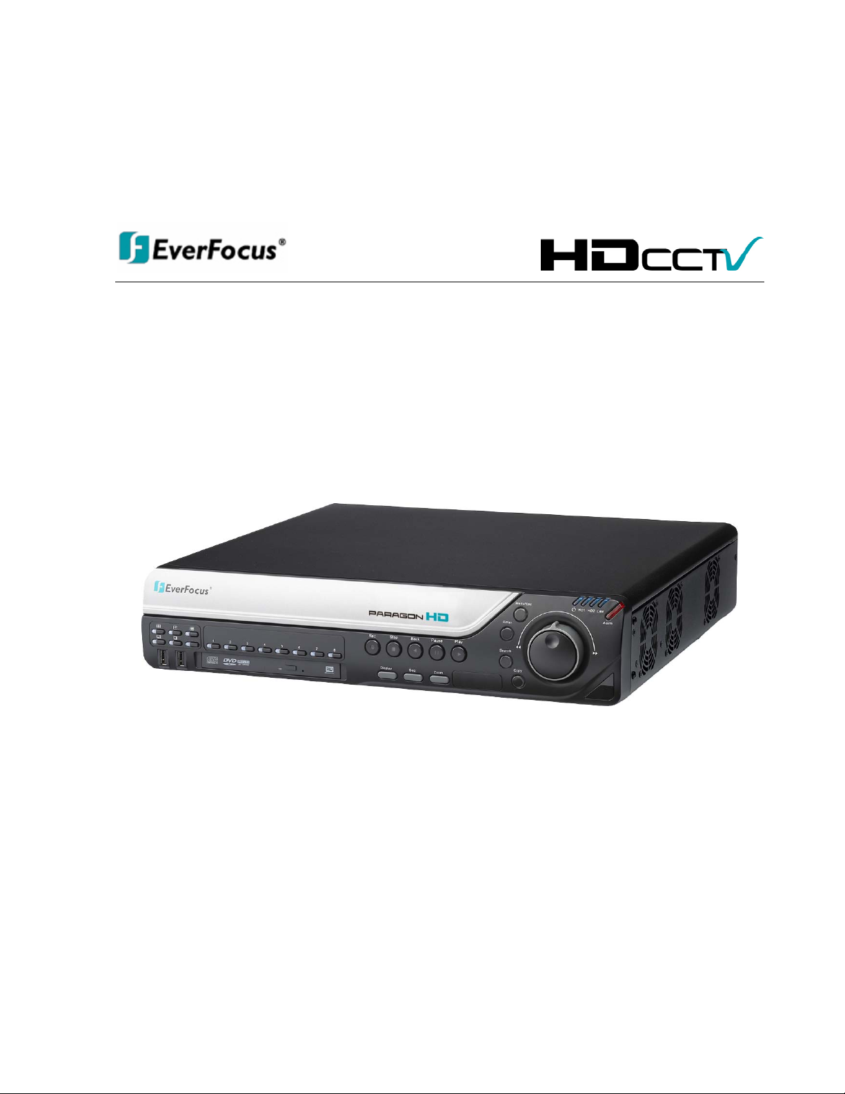
8 channel HD-CCTV Digital Video Recorder
H
D0088
H
D
DVV
D
R
R
Page 2

EVERFOCUS ELECTRONICS CORPORATION
EPHD08 DVR
Instruction Manual
2010 EverFocus Electronics Corp
www.everfocus.com
All rights reserved. No part of the contents of this manual may be reproduced or transmitted in any form or by
any means without written permission of the Everfocus Electronics Corporation.
Release Date: Nov. 2010
QuickTime is a registered trademark of the Apple Computer, Inc.
Windows is a registered trademark of the Microsoft Corporation.
Linksys is a registered trademark of the Linksys Corporation.
D-Link is a registered trademark of the D-Link Corporation.
DynDNS is a registered trademark of the DynDNS.org Corporation.
Other product and company names mentioned herein may be the trademarks of their respective owners.
Page 3

Safety Precautions
Refer all work related to the installation of this product to qualified service personnel or system
installers.
Do not block the ventilation openings or slots on the cover.
Do not drop metallic parts through slots. This could permanently damage the appliance. Turn the
power off immediately and contact qualified service personnel for service.
Do not attempt to disassemble the appliance. To prevent electric shock, do not remove screws or
covers. There are no user-serviceable parts inside. Contact qualified service personnel for
maintenance. Handle the appliance with care. Do not strike or shake, as this may damage the
appliance.
Do not expose the appliance to water or moisture, nor try to operate it in wet areas. Do take immediate
action if the appliance becomes wet. Turn the power off and refer servicing to qualified service
personnel. Moisture may damage the appliance and also may cause electric shock.
Do not use strong or abrasive detergents when cleaning the appliance body. Use a dry cloth to clean
the appliance when it is dirty. When the dirt is hard to remove, use a mild detergent and wipe gently.
Do not overload outlets and extension cords as this may result in a risk of fire or electric shock.
Do not operate the appliance beyond its specified temperature, humidity or power source ratings. Do
not use the appliance in an extreme environment where high temperature or high humidity exists. Use
the DVR at indoor type temperatures within 0°C~40°C (32°F~104°F) and at relative humidity between
20%~80%. The input power source for this device is 12VDC though a power supply which operates
from100~240VAC.
Read Instructions
All the safety and operating instructions should be read before the unit is operated.
Retain Instructions
The safety and operating instructions should be retained for future reference.
Heed Warnings
All warnings on the unit and in the operating instructions should be adhered to.
Follow Instructions
All operating and use instructions should be followed.
Cleaning
ii
Page 4
y
Unplug the unit from the outlet before cleaning. Do not use liquid cleaners, abrasive or aerosol
cleaners. Use a damp cloth for cleaning
Attachments
Do not use attachments not recommended by the product manufacturer as they may cause hazards.
Water and Moisture
Do not use this unit near water-for example, near a bath tub, wash bowl, kitchen sink, or laundry tub,
in a wet basement, near a swimming pool, in an unprotected outdoor installation, or any area which is
classified as a wet location.
Servicing
Do not attempt to service this unit by yourself as opening or removing covers may expose you to
dangerous voltage or other hazards. Refer all servicing to qualified service personnel.
Power Cord Protection
Power supply cords should be routed so that they are not likely to be walked on or pinched by items
placed upon or against them, playing particular attention to cords and plugs, convenience receptacles,
and the point where they exit from the appliance.
Object and Liquid Entry
Never push objects of any kind into this unit through openings as they may touch dangerous voltage
points or short-out parts that could result in a fire or electric shock. Never spill liquid of any kind on the
unit.
ATTENTION! This is a class A product which may cause radio interference in a domestic environment; in
this case, the user ma
be urged to take adequate measures.
Federal Communication Commission Interference Statement
This equipment has been tested and found to comply with the limits for a Class A digital device, pursuant to
Part 15 of the FCC Rules. These limits are designed to provide reasonable protection against harmful
interference in a residential installation. This equipment generates, uses and can radiate radio frequency
energy and, if not installed and used in accordance with the instructions, may cause harmful interference to
radio communications. However, there is no guarantee that interference will not occur in a particular
installation. If this equipment does cause harmful interference to radio or television reception, which can be
determined by turning the equipment off and on, the user is encouraged to try to correct the interference by
one of the following measures :
•Reorient or relocate the receiving antenna.
•Increase the separation between the equipment and receiver.
•Connect the equipment into an outlet on a circuit different from that to which the receiver is connected.
•Consult the dealer or an experienced radio/TV technician for help.
FCC Caution: Any changes or modifications not expressly approved by the party responsible for compliance
could void the users’ authority to operate this equipment.
iii
Page 5

WEEE
This Product is RoHS compliant.
The information in this manual was current upon publication. The manufacturer reserves the right to revise and improve his products.
Therefore, all specifications are subject to change without prior notice. Manufacturer is not responsible for misprints or typographical
errors.
Please read this manual carefully before installing and using this unit. Be sure to keep it handy for later reference.
iv
Page 6

TABLE OF CONTENTS
1 PRODUCT OVERVIEW..................................................................................................... 1
1.1 FEATURES....................................................................................................................... 1
1.2 PACKAGE CONTENTS................................................................................................... 2
1.3 SPECIFICATIONS ........................................................................................................... 3
1.4 FRONT PANEL ................................................................................................................ 4
1.5 REAR PANEL................................................................................................................... 6
2 INSTALLATION.................................................................................................................. 8
2.1 HD-CCTV WIRING FOR VIDEO INPUTS ............................................................................... 8
2.1.1 Understanding HD-CCTV signals and wiring ........................................................................................8
2.1.2 HD-CCTV signal.....................................................................................................................................8
2.1.3 Cable types..............................................................................................................................................9
2.1.4 Cable installation..................................................................................................................................10
2.1.5 BNC-plug...............................................................................................................................................10
2.1.6 Extended cable lengths with extender / converter EHA-SRX ................................................................10
2.1.7 Extended cable lengths with fiber optics transmission..........................................................................11
2.1.8 Monitor installation...............................................................................................................................12
2.2 AUDIO INSTALLATION .............................................................................................. 13
2.3 ALARM CONTACTS INSTALLATION....................................................................... 13
2.3.1 Alarm Input Contacts............................................................................................................................13
2.3.2 Alarm Output Relay...............................................................................................................................13
2.4 RS-485 KEYBOARD / PTZ INSTALLATION......................................................................... 14
2.4.1 General RS-485 bus installation ...........................................................................................................14
2.4.2 RS-485 socket pin assignment...............................................................................................................16
2.4.3 EKB-500 connection with network patch cable.....................................................................................16
2.4.4 EKB-500 connection to several DVRs...................................................................................................16
2.4.5 Speed Dome Installation .......................................................................................................................16
2.5 USB-MOUSE INSTALLATION ............................................................................................ 17
2.6 NETWORK CONNECTION .......................................................................................... 17
2.6.1 Direct PC Connection through Crossover Network Cable ...................................................................17
2.6.2 Network Connection through Patch Cable............................................................................................18
2.7 FINAL
INSTALL PROCESS.......................................................................................... 18
3 MOUSE AND FRONT PANEL OPERATI
ON ............................................................... 19
3.1 GENERAL USB MOUSE OPERATION....................................................................... 19
3.1.1 How to select a channel / Enable audio................................................................................................19
3.1.2 OSD Root Menu.....................................................................................................................................19
3.1.3 Operation in the Configuration Menus.................................................................................................20
3.1.4 Field Input Options ...............................................................................................................................20
2.2 G
2.2.1 How to select a channel / Enable audio................................................................................................22
2.2.2 OSD Root Menu.....................................................................................................................................22
ENERAL FRONT PANEL OPERATION ............................................................................... 22
v
Page 7

2.2.3 Front Panel Key Review........................................................................................................................22
2.2.4 Operation in Configuration Menu.........................................................................................................22
2.2.5 Field Input Options ...............................................................................................................................23
3. GENERAL DVR OPERATIONS...................................................................................... 25
3.1 RECORD......................................................................................................................... 25
3.2 LOGIN............................................................................................................................. 25
3.3 SELECT CAMERA OPERATION................................................................................. 26
3.5 PLAYBACK.................................................................................................................... 27
3.6 PTZ.................................................................................................................................. 28
3.6.1 General PTZ control (if PTZ cameras are installed)..................................................................................28
3.6.2 Express Control of PTZ.........................................................................................................................29
3.7 LAYOUT......................................................................................................................... 31
3.7.1 Bring a camera to full screen mode.......................................................................................................31
3.8 CHANNEL
SWITCHING............................................................................................... 31
3.9 DISPLAY ........................................................................................................................ 32
3.10 SEQUENCE.................................................................................................................. 32
3.11 ZOOM........................................................................................................................... 32
3.12 SEARCH....................................................................................................................... 33
3.12.1 Time Search...........................................................................................................................................34
3.12.2 Event Search..........................................................................................................................................35
3.12.3 Smart Search .........................................................................................................................................36
3.13 COPY............................................................................................................................ 39
3.14 LOGOUT...................................................................................................................... 39
4 DVR CONFIGURATION.................................................................................................. 41
4.1 CONFIGURATION MENU............................................................................................ 41
4.2 EXPRESS........................................................................................................................ 41
4.3 CAMERA SETTING ...................................................................................................... 44
4.3.1 Global Setting...............................................................................................................................................44
4.3.2 Basic Setting..........................................................................................................................................45
4.3.3 Motion ...................................................................................................................................................47
4.3.5 Video Loss.............................................................................................................................................50
4.4 RECORD & PLAY SETTING........................................................................................ 51
4.4.1 Record...................................................................................................................................................51
4.4.5 Play .......................................................................................................................................................52
4.5 ALARM & EVENT SETTING....................................................................................... 53
4.5.1 Alarm .....................................................................................................................................................53
4.5.5 Event......................................................................................................................................................55
4.6 SCHEDULE
4.6.1 Express Setup .......................................................................................................................................64
4.6.5 Holidays ................................................................................................................................................65
4.6.6 Schedule ................................................................................................................................................66
4.6.7 Alarm Action .........................................................................................................................................71
SETTING................................................................................................... 64
4.7 NETWORK SETTING.................................................................................................... 74
4.7.1 LAN .......................................................................................................................................................75
4.7.2 EMAIL...................................................................................................................................................77
4.7.3 DDNS ....................................................................................................................................................78
vi
Page 8

4.7.4 Alarm Server .........................................................................................................................................80
4.8 DISK INFORMATION................................................................................................... 81
4.8.1 Disk .......................................................................................................................................................81
4.8.2 Lock.......................................................................................................................................................82
4.9 DISPLAY SETTING....................................................................................................... 83
4.9.1 Monitor OSD.........................................................................................................................................83
4.9.2 Main M/T SEQ ......................................................................................................................................84
4.10 SYSTEM SETTING..................................................................................................... 85
4.10.1 Date/Time..............................................................................................................................................85
4.10.2 Daylight Saving.....................................................................................................................................86
4.10.3 User.......................................................................................................................................................87
4.10.4 I/O Control ............................................................................................................................................90
4.10.5 Misc. ......................................................................................................................................................91
4.11 INFORMATION........................................................................................................... 93
4.11.1 System....................................................................................................................................................93
4.11.2 Log.........................................................................................................................................................94
5 NETWORKING OVERVIEW.......................................................................................... 96
5.1 INTRODUCTION TO TCP/IP............................................................................................... 96
5.2 SUBNET MASKS................................................................................................................ 96
5.3 GATEWAY ADDRESS......................................................................................................... 96
5.4 VIRTUAL PORTS................................................................................................................ 97
5.5 PRE-INSTALLATION .......................................................................................................... 97
5.6 WHAT IS YOUR NETWORK SETUP?.................................................................................... 98
5.7 SIMPLE ONE TO ONE CONNECTION................................................................................... 99
5.8 DIRECT HIGH SPEED MODEM CONNECTION ................................................................... 104
5.9 ROUTER OR LAN CONNECTION...................................................................................... 106
6 REMOTE OPERATION FROM BROWSER.................................................................... 109
6.1 CONNECTING TO EPHD08............................................................................................ 109
6.2 BROWSER SECURITY SETTING .................................................................................. 110
6.2.1 Installing ActiveX controls..................................................................................................................110
6.2.2 Enabling ActiveX Controls..................................................................................................................113
6.3 REMOTE LIVE VIEW................................................................................................. 116
6.4 REMOTE PLAYBACK................................................................................................ 118
7 EVERFOCUS DDNS SETUP
.......................................................................................... 119
8 LINKSYS & D-LINK PORT FORWARDING ............................................................. 121
8.2 TYPICAL LINKSYS PORT FORWARDING
............................................................. 121
8.3 TYPICAL D-LINK PORT FORWARDING ................................................................ 123
9 TROUBLESHOOTING................................................................................................... 126
APPENDIX A: TIMING OF ALARM MODES.................................................................... 128
APPENDIX B: EXPRESS SETUP RECORDING VALUE SELECTION RULES
.......... 131
APPENDIX C: REMOTE CONTROL................................................................................... 133
vii
Page 9

Chapter
1
1 PRODUCT O VERVIEW
Join the revolution in CCTV technology: deliver and record High Definition image quality using traditional
coaxial cable*! Retain plug-and-play ease of installation: select leading edge EverFocus HD CCTV
cameras that use the advanced HD-SDI transfer format to send full HD, megapixel resolution digital video
over the same coax that once carried only standard definition video; the Paragon HD DVR will record using
H.264 compression technology and play back these crystal clear HD images in real time! Install a new HD
system without changing your installation methods, without switches, routers and IP addresses. Or, make
the transition from SD/D1 to Full HD as easy as attaching new EverFocus HD-CCTV cameras to the
existing coax and power, and upgrading the DVR to the EPHD08 HD DVR. The Paragon HD DVR and HDCCTV cameras provide tremendous advances in resolution over traditional analog CCTV cameras. Get
“megapixel” performance without “network headaches”. EverFocus Electronics puts the future in your
hands – TODAY!
1.1 FEA TU RES
Choice of 1080i or 720p HD CCTV camera support for superlative image clarity
H.264 Compression format for efficient recording
HD real time recording and playback rate for all cameras (at 720p)
HDMI 1080p and VGA multiplex view main monitor outputs
Simultaneous high resolution recording (1080p/720p) with reduced bandwidth remote view streaming
MobileView support: check your home or business on-the-go from your PDA or SmartPhone
Pentaplex operation (simultaneous live, recording, playback, archiving and remote viewing)
Free EverFocus DDNS service – static IP address is not required for reliable remote access
User friendly GUI with graphical icons and visual indicators
Support for 4 fixed internal HDD plus eSATA external HDD
Multiple control inputs: mouse/front panel/IR remote controller/EKB500 keyboard
Express setup: a unique menu option for quick & easy installation
Express archive: archive video instantly (to USB) while playing back
Express playback: simple point, click and drag the playback bar to view desired recordings
Express search: use the intuitive playback bar with simple drag & drop operations
Smart Search: Quickly identify motion in areas of interest from recorded video
Remote configuration support from the built-in web interface
Gigabit Ethernet interface for remote network viewing and control
On-screen PTZ control via mouse or front panel
Per channel audio recording capabilities
Built-in DVD burner
1
Page 10

3 USB2.0 ports for video archive and mouse usage
Multi –language support
19” rack mountable – rack ears included
1.2 PA CKA GE CONTENTS
HDD fixing bracket x 4 (Internal HDD model)
DVR fixing bracket x 2
Remote controller x 1
Battery x 2
Shockproof rubber x 16(Internal HDD model)
Screws x 16(Internal HDD model)
Expanding screws x 16(Internal HDD model)
SATA cable (Internal HDD model x4)
Power cord x 1
Mouse x 1
DVR x 1
User manual x 1
Quick Installation Guide x 1
2
Page 11

1.3 SPECIFICA TIO NS
Paragon HD DVR – EPHD08
HD-SDI Camera Video Inputs 8 BNC connectors
Recording Rate/Resolution 120/100 FPS @1080p; 15/12,5 FPS per channel
240/200 FPS @720p; 30/25 FPS per channel
Playback Rate/Resolution 15/12.5 FPS @ 1080p; 120/100FPS @ 480x256
30/25 FPS @720p; 240/200 FPS @ 320x176
Compression Format H.264
Dual Streaming Yes
Mobile Viewing on PDA/Smartphone Yes; various platforms and browsers supported
Pentaplex Operation Simultaneous Live, Recording, Playback, Archive and Remote
Viewing
Video Output Main Monitor1080p 60 Hz vert, 68 KHz hor. (HDMI socket Type A 19
pin f)
VGA 1920 x 1080 @ 60 Hz vert, 68 KHz hor. (D-Sub socket 15 pin f)
Audio Input/Output (RCA) 8 Inputs / 1 Output
Recording Mode Manual, Schedule and Event
Playback Search Date/Time Search, Event Search, Smart Search
Alarm In 8 Alarm Inputs
Alarm Out 2 Alarm Outputs – Form “C” rated at 30VDC, 1A
Video Pause Yes
Video Loss Detection Yes
Motion Detection Yes
Event Log Yes
Watch Dog Timer Yes
Internal HDD 4 Internal HDD
External HDD 1 eSATA
Built-in DVD Burner Slim Type DVD Burner
User Interface GUI (Graphical User Interface – easy mouse or front panel
navigation)
OS Embedded Linux
Network/Protocol Gigabit Ethernet; TCP-IP / DHCP/ PPPoE / DDNS / UDP / SMTP /
SSL / RTP / RTSP / NTP
USB 3 USB 2.0 port (2 on Front Panel, 1 on Back Panel)
Schedule Setting Supports Express and Advanced Schedule Setting
User Access 3 Levels of User Access Support
RS-232 9-pin D-Sub socket (male)
RS-485 1 RS485 (3 Terminal connector)
Power Source 100VAC~240VAC
Power Consumption 130W max. with 4 x HDD
Dimensions (L x W x H) 410 x 430 x 88 mm / 16.2" x 16.9" x 3.5"
Temperature 0°C~40°C / 32°F~104°F (20~80% humidity)
Supported PTZ Protocols
EverFocus, Pelco D, Pelco P, Samsung, Transparent
3
Page 12
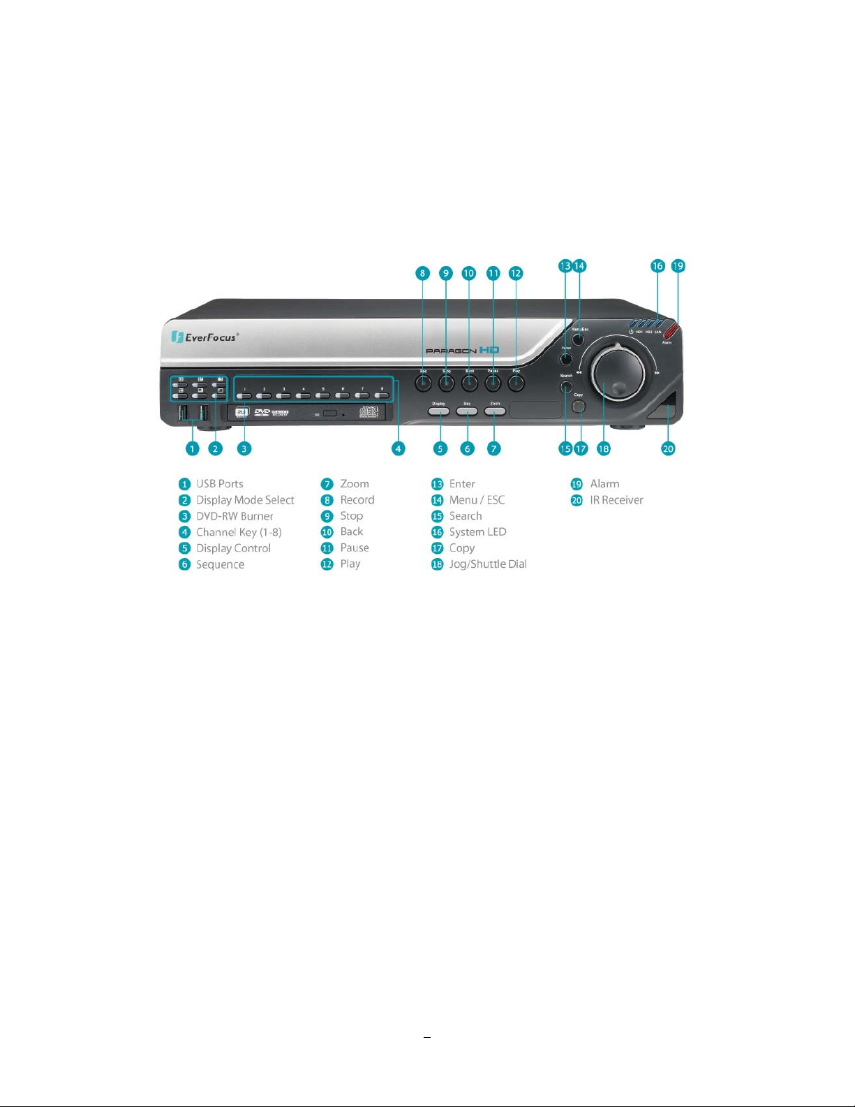
1.4 FRONT PANEL
Your primary interaction with your new DVR will be through the Front Panel buttons and their
corresponding buttons on the included IR Remote Control. Take a moment to learn where the keys are as
the remainder of the manual will refer to them often.
Figure 1-1 Front Panel
1) 2 x USB-2.0 port for USB mouse, USB-Flash-Drive
2) Multiview Keys:
Full, 4x, 6x, 7x, 8x, 9x and PIP. The LED will show the selected screen layout.
3) DVD+RW Burner: DVD+RW drive for video data export.
4) Channel keys 1~8 for full screen display of selected channel. The LED will show the active channel.
5) DISPLAY: The DISPLAY key switches titles and status messages on the Screen in 4 steps. For
details please consult chapter 3.9 DISPLAY.
6) SEQ: Sequence key for automatic switching of a defined camera sequence
7) ZOOM:
4x electronical zoom.
For details please consult chapter 3.11 ZOOM.
Note:
The Zoom key is only active in Full screen.
4
Page 13

8) Record: RECORD key for manual start of recording / recording standby (event recording).
LED will be ON if DVR is recording or in record standby.
9) STOP: STOP key for Playback and Record
10) BACK: Reverse Playback key
11) PAUSE: Image freeze in playback mode
12) PLAY: Playback key
13) ENTER: Enter Key for menu operation and alarm acknowledge Turn camera audio ON/OFF when
viewing full screen camera. For more details, please refer to Chapter 0.
14) MENU/ESC: Used to bring up Main Menu or exit from sub-Menus.
15) SEARCH: The SEARCH key opens the SEARCH menu, details in chapter 3.12 SEARCH.
16) System LED
POWER: LED indicating power on.
HDD1/2: LED indicating HDD1 / HDD2 active
HDD1: Internal HDDs in DVR
HDD2: External HDDs connected by eSATA port
LAN: LED for network traffic
17) COPY: The COPY key opens the menu for video data export, details in chapter 3.13 COPY.
18) JOG/SHUTTLE: Shuttle (outer wheel): In playback mode, use the SHUTTLE for fast forward / fast
reverse playback.
JOG (inner wheel): In PAUSE mode, use the jog to move frame by frame. Within
menu functions, use the jog to adjust the values / parameters. Use Jog to highlight
Jog
Shuttle
individual cameras.
Use either Shuttle or Jog to switch between MENU parameters.
19) ALARM: LED for alarm status
20) IR Receiver: Receiver for IR remote control
5
Page 14
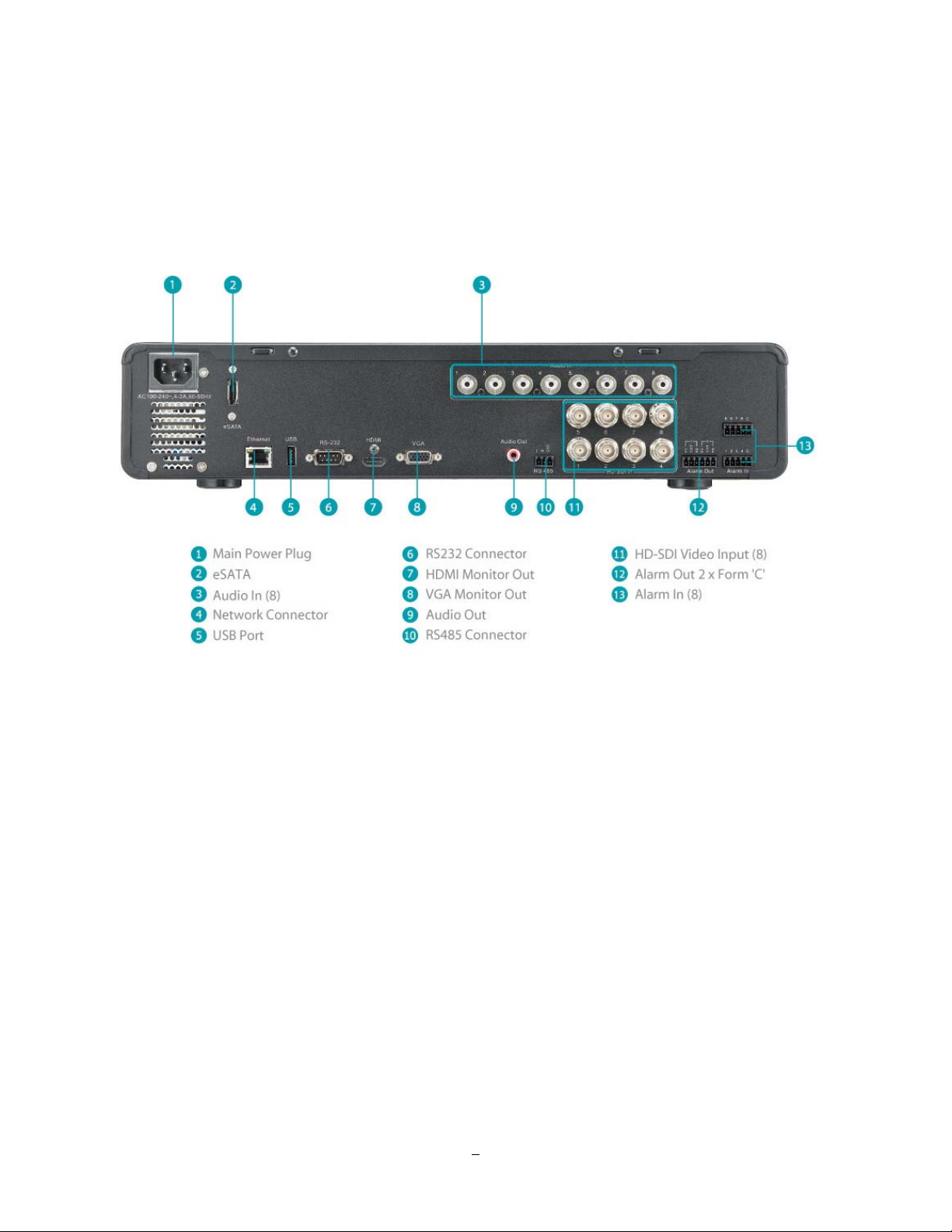
1.5 REAR PANEL
During initial setup you will be connecting your DVR to multiple input and output devices. This is done
through the rear panel.
Figure 1-2 Rear Panel
1
○
POWER: Power input 100~240 VAC.
2
eSATA port: Used for external SATA HDD bay
○
3
○
Audio In: Connect line level output of an audio preamplifier to the audio input connection
corresponding to the appropriate camera.
4
LAN: RJ-45 socket for 1 GB network interface, connectabe also to 10/100 Mbps network
○
structures. There are two LEDs on the LAN jack; Green LED means network is
connected, amber LED flickers when data is being exchanged.
5
○
USB 2.0: USB port recommended for connecting the USB mouse.
6
○
RS232 socket: 9-pin D-Sub RS-232 interface (for service and support purpose)
6
Page 15

7
○
HDMI Out: Provides an uncompressed all-digital video interface between the HD DVR and HDMI-
compatible monitor. HDMI output format is 1920x1080p 60Hz vertical, 68 KHz
horizontal.
8
○
VGA Out: Connect a VGA monitor to the VGA output connection. DVR can auto detect the best
resolution from the connected VGA monitor. If DVR detection fails, the default
resolution will be 1920x1080 60Hz vertical, 68 KHz horizontal.
9
○
Audio Out: Connect to the line level input of an audio amplifier.
10
○
RS485 socket: For remote control via RS-485 keyboards and telemetry control for attached PTZ
devices
11
HD-SDI Video In: Connect HD-SDI camera’s video output or other HD-SDI video source to the video
○
input connection.
12
○
Alarm Out: N.C or N.O type alarm out (form “C”).
13
○
Alarm In: Connect up to 8 alarm inputs, selectable between N.O./N.C. contacts.
7
Page 16
2 Installation
2.1 HD-CCTV wiring for video inputs
2.1.1 Understanding HD-CCTV signals and wiring
Even if EverFocus HD-CCT
technology - the requirements for wiring and cable types are some different.
This chapter explains some basic facts for HD-CCTV signals and cable requirements.
2.1.2 HD-CCTV signal
V equipment uses coaxial cable and BNC type plugs similar to standard CCTV
In result to the high resolution and uncompressed image transmission from the camera high frequencies
are used for HD-CCT
EverFocus HD-CCTV technology is mostly based on the SMPTE-292M standard, which defines HD-SDI
(High Definition - Serial Digital Interface) video transmission.
In classic CCTV video standards PAL/NTSC the frequency bandwidth is < 6MHz for high resolution
cameras.
HD-CCTV works with up to 1.5 GHz, so this technology requires ~ 250 times higher frequency than
PAL/NTSC based CCTV.
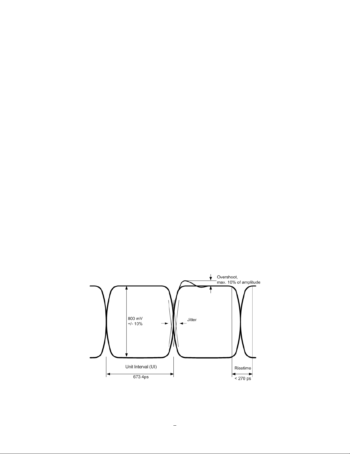
The figure below shows the basic timing and signal levels of a full HD (1920x1080) signal:
V signal transmission.
Timing of HD-SDI signal ("Eye"-diagram)
The diagram shows the total difference of HD-CCTV signals to classic NTSC or PAL signals.
8
Page 17

Well known signal parts such as Sync, Burst and others do not exist here.
The high frequencies do not allow a signal evaluation by standard oscilloscopes or other standard video
measurement tools. Only quite expensive HD-SDI analyzers and upscale HF - oscilloscopes could be used
here. In most cases such equipment is not available at installation site.
For this reason a careful specification of the cable type is mandatory for system planning, especially in
applications with long cable distances.
2.1.3 Cable types
The short description of HD-SDI signals above explains, why high frequency attenuation of the used video
cable has a high influence on the achievable maximum cable length. Further on also the Return Loss of the
coaxial cable and plug influences signal stability.
The standard RG-59 cable types - the most common in the CCTV industry - are originally designed for
lower frequencies.
However, due to the new optimized receiver interfaces of EverFocus HD-CCTV equipment it is also
possible to use standard RG-59 cable for distances of over 100m.
High quality, low loss RG-59 cable types allow distances up to 160m.
Longer cable distances can be achieved with low loss RG-6 or RG-11 type coaxial cables.
Generally are cable types with 75 Ω impedance required.
Attenuation at 1 GHz: < 32 dB per 100m (328 feet)
Return Loss attenuation: > 20 dB
Impedance: 75 Ω
The table below gives an orientation for achievable cable distances:
Cable Type Attenuation in dB at 1
GHz per 100 m / 328 ft
Max. Cable distance in
m ft
RG-59 24 ~ 40 * 70 ~ 160 230~520
RG-6 15 ~ 35 * 100 ~ 190 330~620
RG-11, CATV-
8 ~ 16 * 180 ~< 250 590~<820
lowloss cables
* Low quality cable may have higher attenuation
9
Page 18
2.1.4 Cable installation
Please make sure, that the coaxial cable is not squeezed at any position.
Also the max. bending radius defined by the cable manufacturer should be considered.
General rule: maximum bending radius = 10 x outer cable diameter
Bending creates pressure on the center conductor, causing it to move through the dielectric toward the
inside of the bend. This affects impedance and return loss and reduces the maximum possible cable length.
Please try to avoid any BNC - adapter or any connectors in the BNC cable.
Looping HD-SDI signals by BNC T-connectors to other devices is not possible.
2.1.5 BNC-plug
Also the BNC - plug plays an important role for clear HD-CCTV signal transmission.
Standard BNC plugs for CCTV have a quite high attenuation and may cause return losses due to reflection
effects.
We recommend using of HD-Video approved BNC plugs.
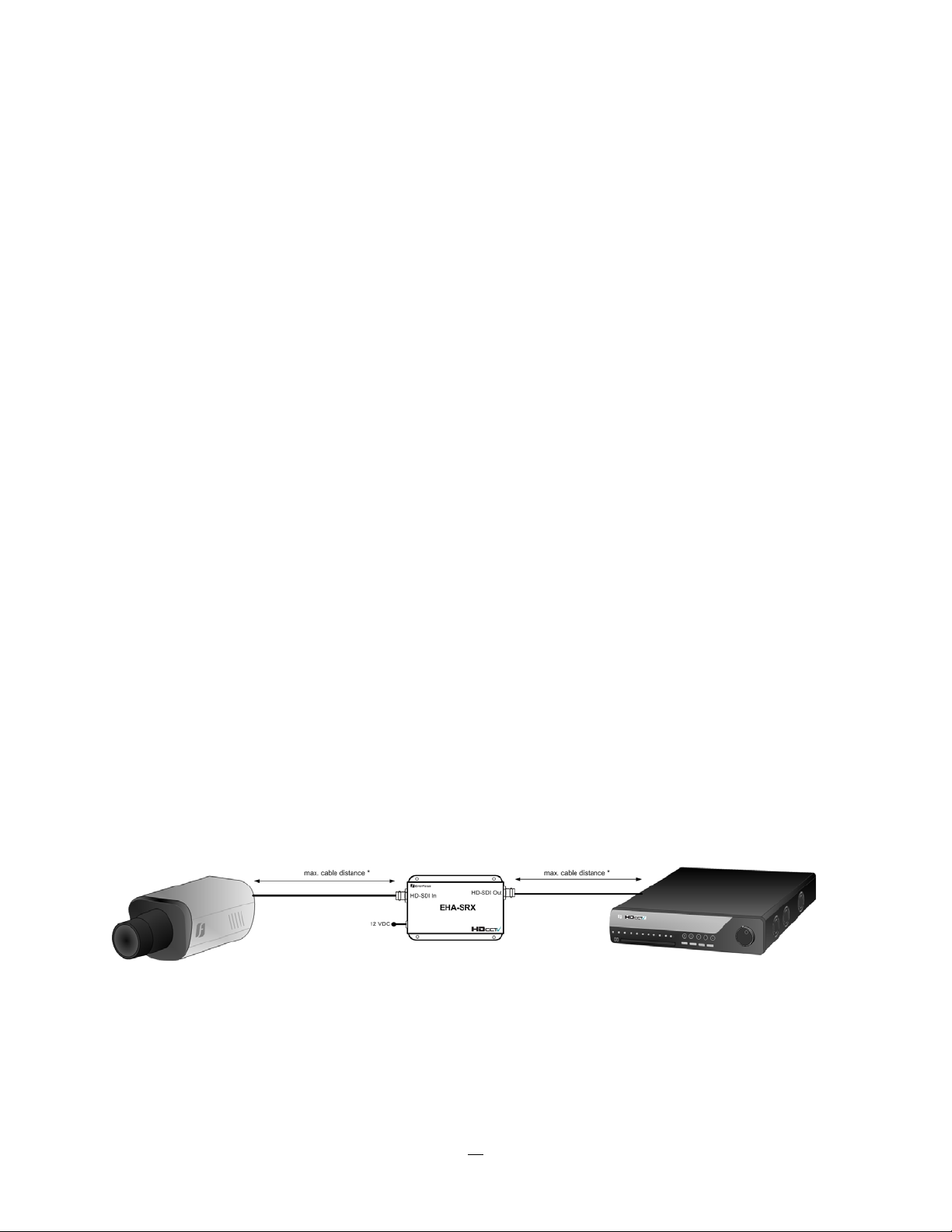
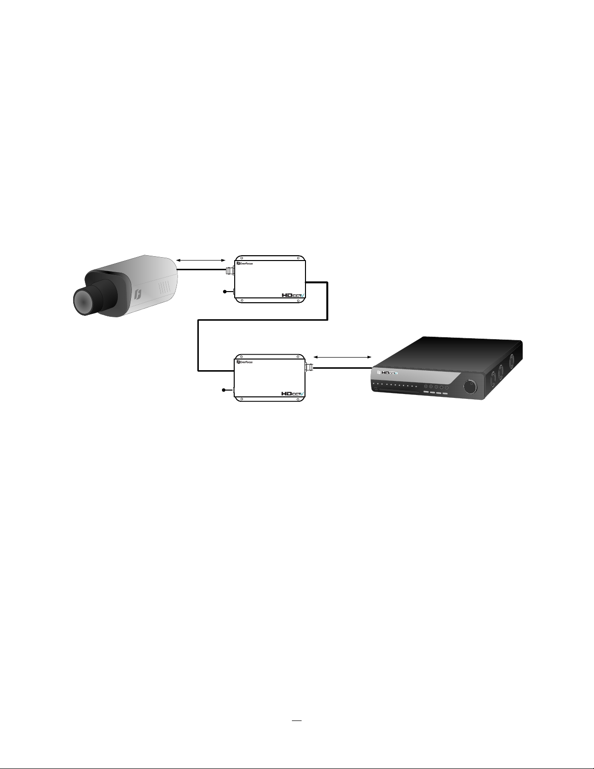
2.1.6 Extended cable lengths with repeater EHA-RPT / converter EHASRX
The maximum cable distance between camera and DVR and DVR / repeater can be doubled by installing
EHA-RPT in the video line. EHA-SRX is a combined HD-SDI cable extender and HD-SDI to HDMI
converter.
The HD-SDI output of EHA-SRX allows adding one more complete coaxial cable length.
* max. coaxial cable depends on installed cable type
10
Page 19
2.1.7 Extended cable lengths with fiber optics transmission
The maximum distance between camera and receiving device can be extended by fiber optics cable.
The transmitters and receivers are available for multi-mode and single-mode fiber cables:
EHA-FTX-MM: Fiber optics transmitter multi-mode, max. transmission distance 500 m
EHA-FTX-SM: Fiber optics transmitter single-mode, max. transmission distance 21 Km
EHA-RTX-MM: Fiber optics receiver multi-mode, max. transmission distance 500 m
EHA-RTX-SM: Fiber optics receiver single-mode, max. transmission distance 21 Km
max. coaxial cable distance *
12 VDC
HD-SDI In
EHA-FTX
Fiber Optical Cable
EHA-....X-MM:Multi Mode - up to 500 m
EHA-....X-SM: Single Mode: up to 21 Km
Fiber out
max. coaxial cable distance *
HD-SDI Out
EHA-FRX
12 VDC
Fiber in
12 VDC
* max. coaxial cable depends on installed cable type
The fiber optics interface of EHA-FTX / EHA-FRX requires LC type plugs for the fiber optics cable.
11
Page 20
2.1.8 Monitor installation
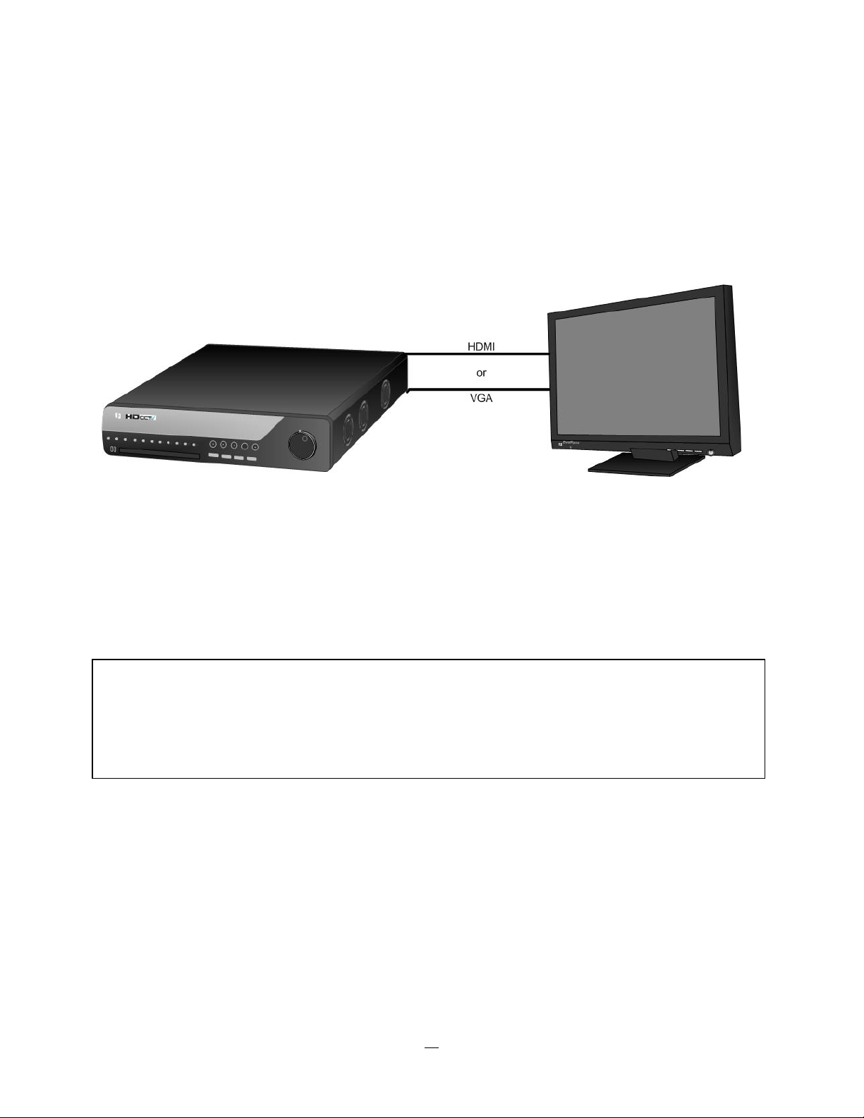
The EPHD-8 provides 2 main monitor outputs with identical functionality - VGA and HDMI.
Both outputs can be used simultaneously and deliver full HD output resolution ( 1920x1080, progressive,
60 Hz. vert., 68 KHz hor.).
Make sure that the connected monitor's specifications comply with these resolution requirements.
Please do not exceed the max. HDMI cable length of 15 m.
For cable length up to 3 m standard HDMI cables mostly work well, for longer distances (especially in the
15m range) please use only high quality HDMI cable.
!!Warning!!
Please make sure the resolution of all cameras are the same as the DVR‘s setting. Otherwise, DVR cannot
display video correctly. The default resolution of DVR is 1920x1080. Please change the camera‘s setting to
1920x1080 before connecting to the DVR. Or both DVR and cameras can be set to 1280x720 as the
resolution configuration.
12
Page 21

2.2 AUDIO INSTALLA TION
This DVR provides 8 line level audio input and 1 line level audio output.
ATTENTION: The direct connection of a non-amplified microphone is not supported (a microphone
amplifier is required). The audio output requires an amplifier to drive a speaker or headphones.
The installation must be connected with audio coax cable and RCA plugs.
AUDIO RECORDING FUNCTIONALITY:
Audio channels are assigned to the video channels 1~8 for recording and export. Activation of audio
recording is done in CAMERA > BASIC menu.
Please check and always comply with local laws and regulations when using audio recording.
The audio channel is always recorded together with video and is independent of the image recording rate.
2.3 ALARM CONT A CTS INSTALLA TION
The alarm input can be used to start recording or for recording rate adjustment. In addition, alarm reactions
such as camera display on the monitor, buzzer, e-mail and network alarm are available. The alarm output
relay can be switched if required. Alarm input response actions can be controlled according to a flexible
schedule.
2.3.1 Alarm Input Contacts
This DVR provides one alarm input per camera. The input is programmable N.O. (Normal Open) or N.C.
(Normal Closed) Input has to be switched by dry contacts.
Alarm input with N.O. (Normal Open) contact Alarm input with N.C. (Normal Closed) contact
in idle state in idle state
All settings are programmed in the ALARM menu.
2.3.2 Alarm Output Relay
The relay outputs provide either Normally Open or Normally Closed dry contacts.
13
Page 22
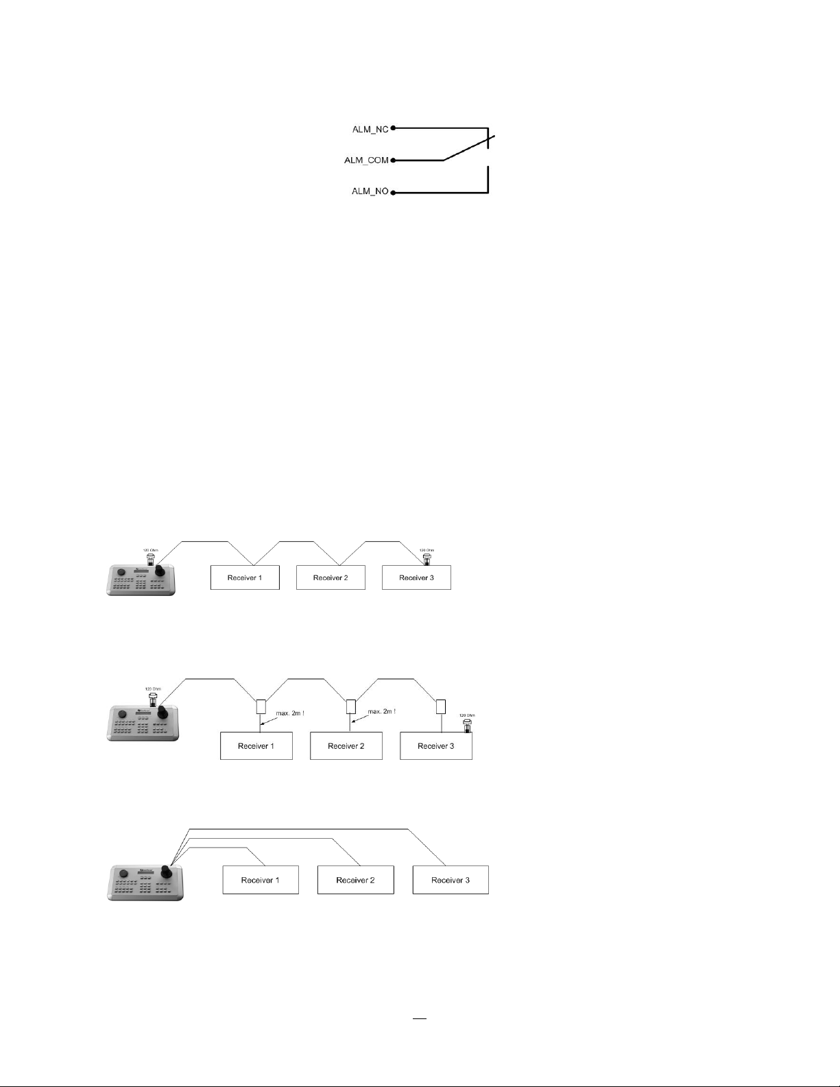
Output relay in idle state
2.4 RS-485 keyboard / PTZ Installation
All functions can be remote-controlled by the EKB-500 universal keyboard. Using the EEPbus protocol,
digital video recorders, keyboards and speed domes can be installed on one single RS-485 bus. One
system can comprise up to 8 keyboards.
2.4.1 General RS-485 bus installation
The EKB-500 keyboard uses a RS-485 simplex wiring; the signal is transferred via a single twisted pair line.
CAT5 network cable is recommended, UTP version (unshielded) is sufficient for normal applications. A
shielded cable should be used if the installed cables are expected to be highly susceptible to interference.
The number of devices installed in one bus is limited to 32, and the maximum cable length is 3,900 feet.
Both of these can be expanded using a signal distributor EverFocus Model EDA997A (see below).
Both the first and the last device in series should be terminated with 120 Ohm resistance in order to
minimize line reflections.
RS-485 bus serial wiring
Cable length from box to device („Stubs“) has to be limited to 2m using connector boxes.
RS-485 bus serial wiring with connector boxes and connection cable
Direct RS-485 bus star wiring is not supported unless using an EverFocus Model EDA997A (see below).
Improper RS-485 bus star wiring
14
Page 23
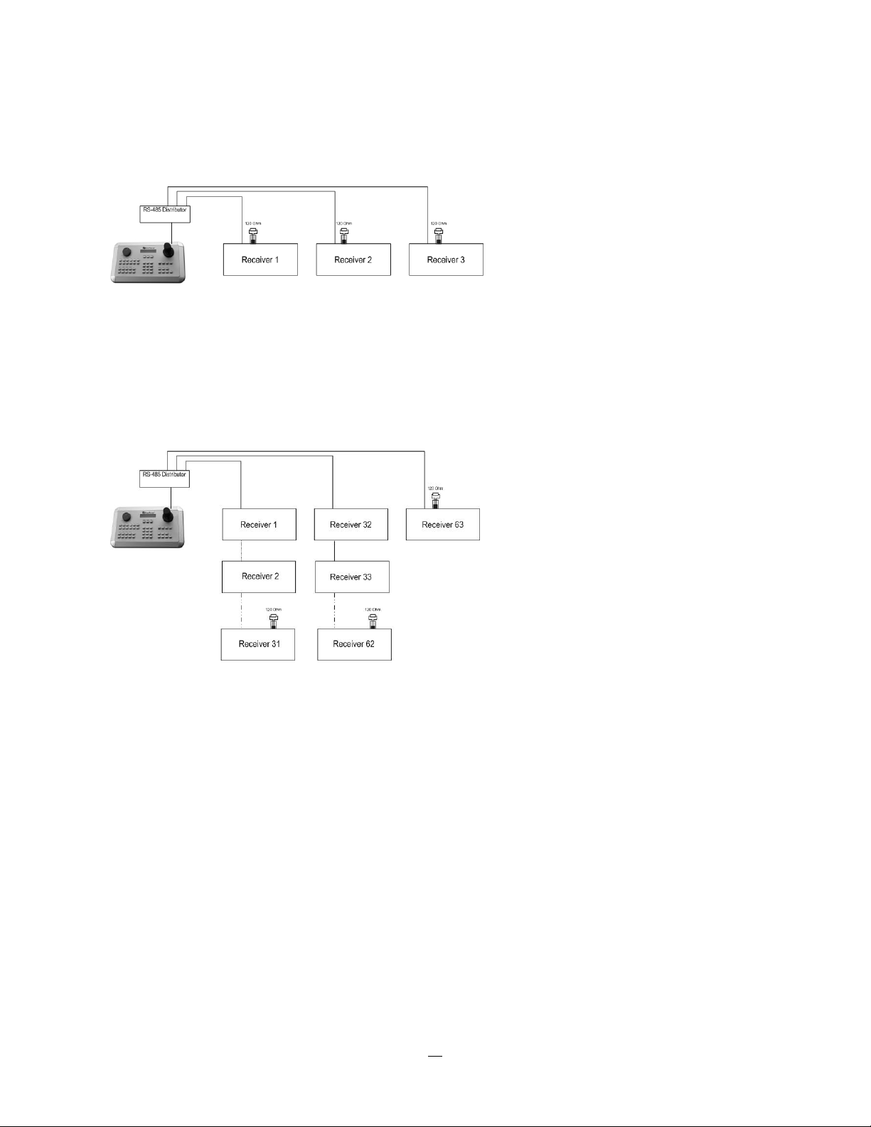
An EDA997A RS-485 signal distributor may be used to use a star wiring configuration.
Star wiring with RS-485 signal distributor
A RS-485 distributor can also be used to increase the maximum number of devices on the bus as well as
the total range. Each distributor output provides another RS-485 bus. This allows each output to extend an
additional 1200m, and it also enables the additional connection of 31 further devices to each output (the
output itself represents one device).
The maximum system expandability depends on the RS-485 address range of the installed devices.
System expansion with RS-485 signal distributor
ATTENTION: EDA997A signal distributors are unidirectional! This means that the signal only flows from
the input towards the outputs. Therefore, e.g. the interconnection of several keyboards is not possible with
these types of signal distributor!
15
Page 24

2.4.2 RS-485 socket pin assignment
The RS485 pin assignment is as follows:
2.4.3 EKB-500 connection with network patch cable
For a simple, short distance installation, recorder and keyboard can be connected directly using a standard
CAT5 networ
k cable with an 8-pin connector at only one end, and at the other end the Pin 3 wire connected
to RS485 “+” (plus) and the pin 6 wire connected to RS-485 “-“ (minus).
2.4.4 EKB-500 connection to several DVRs
For long distance installations connecting several DVRs, please use an EDA997A signal distributor to
connect. For further details on keyboard connection, please refer to the EKB-500 manual.
RS-485 port communication settings are configured in the I/O CONTROL menu (Section 5.10.4 System
Setup: I/O
- control).
2.4.5 Speed Dome Installation
Speed dome or telemetry receiver pan/tilt/zoom control is available through web browser or the optional
PowerCon software if the DVR is connected to a network. Local telemetry control is provided by USB mouse control or by the optional EKB-500 keyboard.
Supported protocols: EverFocus, Pelco-D, Pelco-P, Samsung, Transparent
Required DVR settings: RS-485 receiver address in CAMERA menu
(Section 4.3.2)
RS-485 parameters and protocol in the I/O CONTROL menu
(Section 4.10.4)
ATTENTION: Some Pelco-D / -P protocol domes and receivers require an address offset of -1, i.e. the
address assigned to the dome / receiver in the DVR camera menu must be 1 below the address set in the
dome / receiver itself!
16
Page 25
2.5 USB-Mouse installation
Connect the USB mouse to one of the 2 USB ports. (This can be done while DVR is powered on)
NOTE: Recommended mouse types are Logitech® and Microsoft® wired USB wheel-mouse. Wireless
USB mouse is not supported.
2.6 NETWORK CONNECTION
This section only describes physical connection to an Ethernet network. This step must be completed
before the DVR can connect to the network. There are two basic types of connection:
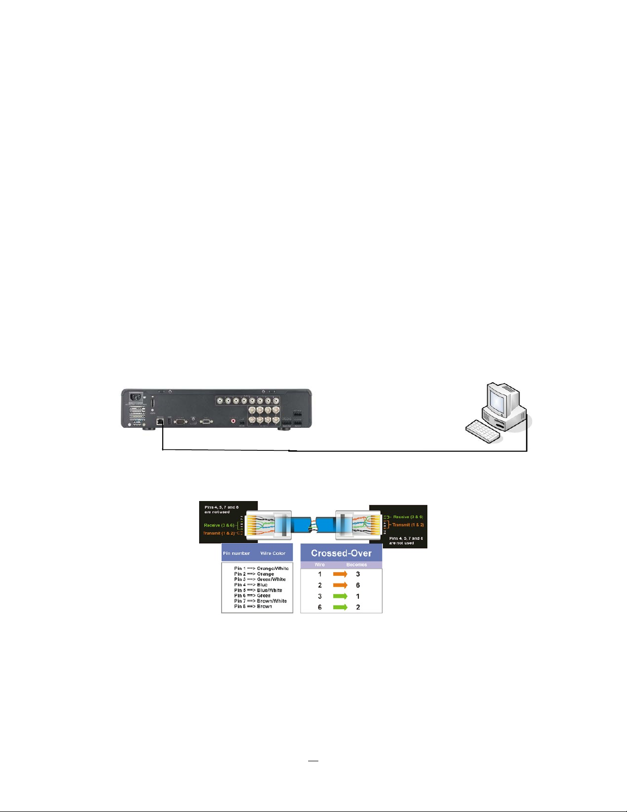
2.6.1 Direct PC Connection through Crossover Network Cable
The point-to-point connection of DVR and PC requires a crossover (crossed) network cable. This type of
connection is ONLY used for direct connection to a single PC. Make sure that the PC is equipped with a
10/100 Mbps compatible network connection.
Figure 2-1 Direct PC Connection
Pinout of crossover-cable
17
Page 26
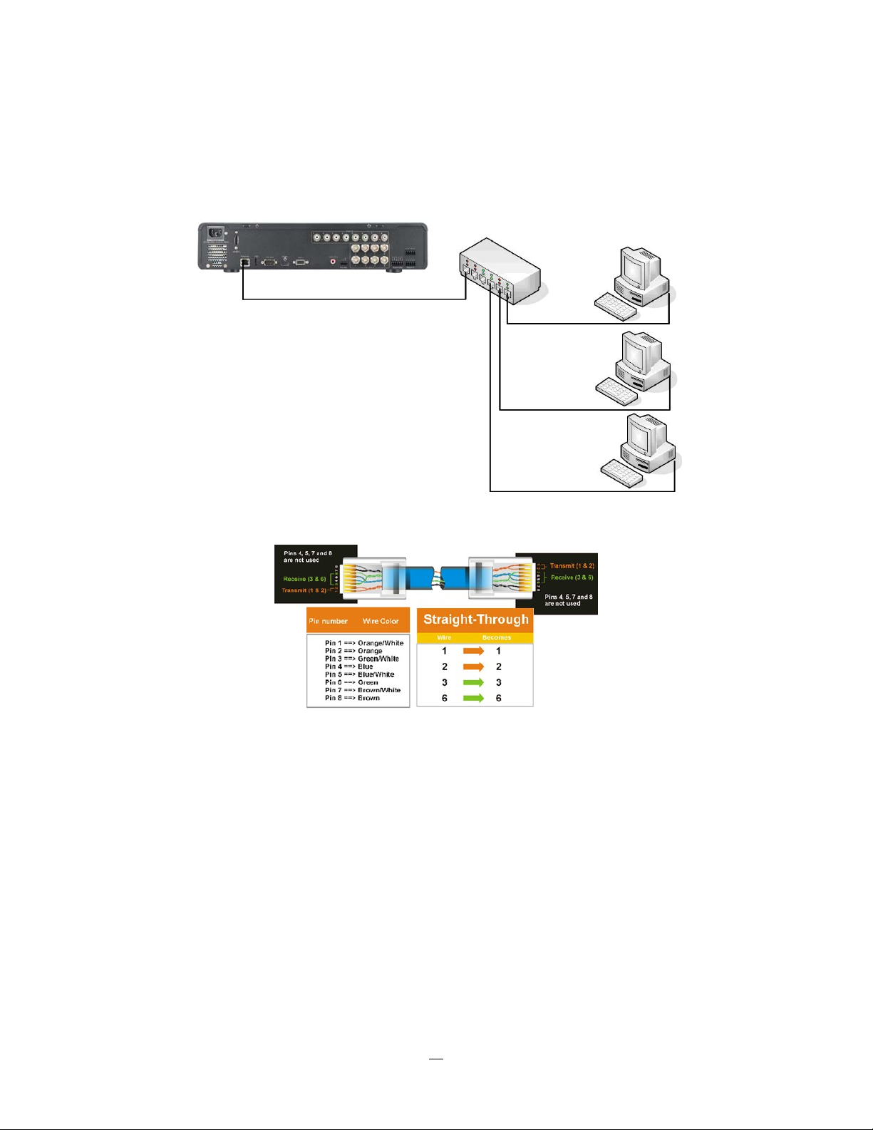
2.6.2 Network Connection through Patch Cable
The connection to an existing network requires a normal patch cable (straight-through). The illustration
shows the connection to a network switch or router.
Figure 2-2 Network Connection through Patch Cable
Pinout of straight patch cable
2.7 FINAL INSTALL PROCESS
Once you have completed the basic wiring connections, you are ready to turn on the DVR. Simply plug in
the power source. The POWER LED will light up if power is normal. Once the system has finished loading,
you can begin to set up the menu options for the DVR.
18
Page 27

Chapter
3
3 MOUSE AND FRONT PANEL OPERA TION
EPHD08 DVRs support multiple sources to control the DVR. It can be controlled with a mouse, the front
panel, an EKB500, and the handheld IR remote control.
This chapter will cover the basic operation using the mouse and the front panel buttons.
3.1 GENERAL USB MOUSE OPERA TION
3.1.1 How to select a channel / Enable audio
1. In a view consisting of more than one channel, users can select a channel by clicking once on the
desired channel screen. The selected screen will be highlighted by a white frame.
2. Double clicking on a channel screen will display full screen for this channel.
3. To enable audio out, click the audio icon (ex: ) at lower side of the screen. This system has only
one audio out. Click this button to enable or disable the audio-out mode.
3.1.2 OSD Root Menu
1. Right-click the mouse to obtain the DVR menu bar (see Figure 3-1 OSD Root Menu ). When you move
the mouse over each icon, its title will be displayed at the top of the control bar.
Figure 3-1 OSD Root Menu
2. Click on any icon to perform that action. These actions are covered in detail in Chapter 3.
3. Click the “X” in the top-right corner to close the DVR control bar.
19
Page 28

3.1.3 Operation in the Configuration Menus
Click on the
icon to access the Configuration Menu.
The Configuration menu screens (shown in Figure 3-2 OSD Menu) are divided into 3 main sections.
1
2
3
Figure 3-2 OSD Menu
1. In section 1, there are ten setup options available. Move the mouse over an icon and click to select it.
2. In section 2, the choices for the selected icon will be displayed. Click on a choice to select it.
3. In section 3, all the options for the selected choice will be available. Click on a field to make changes.
3.1.4 Field Input Opt
ions
The following are examples of different types of fields available in the Configuration menu.
Textbox: Click on the box and an on-screen keyboard will appear*. (see
note about the on-screen keyboard below)
Dropdown box: Click on the down arrow to see all selections, then directly click on
an option to select it.
Check box: Click on the box to enable it (checked) or disable it (unchecked).
Button: Click the button to execute the function.
20
Page 29

Bar: Click and hold on the bar to adjust the set point Left or Right.
* Note about on-screen keyboard:
Click on a button to input that character.
The buttons on the right and bottom have the following functions:
Space Enter a space
Caps Switch to capital letters
Delete the letter
Confirm the selection
Move to right
Move to left
21
Page 30

2.2 General Front Panel Operation
2.2.1 How to select a channel / Enable audio
1. In a view consisting of more than one channel, dial the jog/shuttle clockwise or counterclockwis
e to
scroll through each channel that is displayed. The selected channel will be highlighted by white frame.
Dial the jog/shuttle clockwise or counterclockwise when the last/first camera is highlighted will select
all cameras.
2. While channel #1 is selected, press the “Enter” button to turn Audio On/ Off.
2.2.2 OSD Root Menu
1. Press “Me
nu” key to display the DVR menu bar. Dial the jog/shuttle clockwise or counterclockwise to
scroll over each icon. The title for each icon will be displayed on top of the menu bar.
2. Press “Enter” key on any icon to perform that action. These actions are covered in detail in Chapter 3
3. Press “Menu” to close the DVR menu bar.
2.2.3 Front Panel Key Review
The basic principle of front panel operation is to use the jog/shuttle to navigate among the menu items. Use
the “Enter” key to confirm a selection or enter the next level menu. Press the “Menu” key to enter the Main
Menu or exit from the current level of the menu.
2.2.4 Operation in Configuration Menu
Press “Menu”, use the jog/shuttle to highlight the “Configuration” icon, and press “Enter” with
“Configuration” icon highlighted to bring up the Configuration menu.
NOTE: If the require password option is active, you will need to log in first. Refer to “Section 3.2 LOGIN” for
information on logging in. The menu (shown in
Figure 3-3 OSD Menu ) is divided into 3 main sections.
22
Page 31

1
2
3
Figure 3-3 OSD Menu
1. In section 1, there are ten setup options available. Use the jog/shuttle to highlight an icon and press
“Enter” to select it.
2. In section 2, the main choices for the selected icon will be displayed. Use the jog/shuttle to highlight a
choice and press “Enter” to select it.
3. In section 3, all the options for the selected choice will be available here. Use the jog/shuttle to move
between items and press “Enter” to make changes to that item.
Note: press the “Menu” button to go back to the previous menu section/level.
2.2.5 Field Input Options
Textbox: Press Enter key and an on-screen keyboard will appear*. (see
note about on-screen keyboard below)
Dropdown box: Press “Enter” key to show the available options. Use the
jog/shuttle to highlight the desired option and press “Enter” again to select it.
Check box: Press “Enter” key on a setting to enable it (checked) or disable it (unchecked).
Button: Press “Enter” key to execute the function.
23
Page 32

Bar: Press “Enter” key to activate the slider, then use the jog/shuttle to adjust the
setting. Press “Enter” again to finalize the changes.
* Note about on-screen keyboard:
Use the jog/shuttle to highlight each character and press the “Enter” key on the front panel to input the
selected characters. When finished, highlight “Done” and press the “Enter” key on the front panel to
confirm. The buttons on the right and bottom have the following functions:
Space Enter a space
Caps Switch to capital letters
Delete the letter
Confirm the selection
Move to right
Move to left
24
Page 33

Chapter
3
3. GENERAL DVR OPERATIONS
This chapter introduces the operations on major functions including playback, layout change, sequence,
triplex operations, copy, and search.
3.1 RECORD
By default, the DVR will always be in record mode. When the DVR is turned on, it will start to record. The
exceptions are:
1. DVR will not record any uninstalled cameras (Refer to Section 4.3.1 for more details)
2. If a schedule is active, the DVR will follow the record settings of the schedule.
3.2 LOGIN
In order to access EPHD08 options, users may be asked to log in for authority identification. To log in,
follow these steps.
1. Right click on the screen or press the Menu Key to display the Main Menu
2. Choose or click (or press “Enter” key) on the Configuration icon to bring up the following screen:
Figure 3-1 Login page
3. Select the user name from the drop-down list and input the password. The defaults are:
User name: admin (lower case)
Password: 11111111
25
Page 34

+ To input password by mouse: click the password field to bring up the on-screen keyboard (see Figure 3-2
On-screen Keyboard). Click on each button to input the desired characters for the password. When finished,
click “Done” on the on-screen keyboard to confirm the password.
+ To input password using front panel: use the jog/shuttle to select the password field, then press the
“Enter” key to show the on-screen keyboard (see Figure 3-2 On-screen Keyboard). Use the jog/shuttle to
highlight each character and press the “Enter” key on the front panel to input the selected characters.
When finished, highlight “Done” and press the “Enter” key on the front panel to confirm the password.
+ Click (or press “Enter” key when highlighted) on the “Login” button to log in to the system.
Figure 3-2 On-screen Keyboard
3.3 SELECT CAMERA OPERATION
EPHD08 is a pentaplex DVR; users can control each camera individually by selecting that camera. For
camera selection:
Mouse: Right-click the screen, the image will show a white frame on screen if the camera has been
selected. When in quad display mode, press the quad layout icon in layout menu to select all four cameras.
Front panel: Use the jog/shuttle to change the selection. Dial the jog/shuttle clockwise or counterclockwise
when the last/first camera is highlighted will select all cameras.
3.4 CHANGE AUDIO OUTPUT OPERATION
Use the jog/shuttle to select camera #1 and press “Enter” key to switch audio output on and off. An audio
icon will appear on the screen. Please make sure “Record Audio” option under Camera 1 Basic Settings
setup menu is ON if audio recording is required. Also, the audio source and/or audio output amplifier have
to be connected properly in order to utilize the audio functions. Note: Only Cam#1 controls audio, all others
do not control audio.
26
Page 35

0
10
16
3.5 PLAYBACK
The playback bar is the fastest way to show video from the exact time which users want to see. The
playback bar allows a user to see both a time line and the current playback indicator. The user can then
click the time line to move the indicator to the position which they want to see. The operation is as follows:
To playback:
By mouse: Right-click to bring up the menu bar and click on to enter Playback Menu.
By front panel: Press ”Play” key to enter Playback Menu.
The playback bar will show (see figure below):
12 1
2010/05/25 09:09:30PM 2010/05/25 09:09:40PM 2010/05/25 09:10:30PM
14 15
1. Stop key: press to stop playback
2. Slow Reverse key: press to start slow reverse playback
3. Pause key: press to pause playback
4. Slow Forward key: press to start slow forward playback
5. Fast Reverse key: press to start fast reverse playback
6. Reverse key: press to start reverse playback
7. Forward key: press to start forward playback
8. Fast Forward key: press to start fast forward playback
9. Time bar: Move the slider on the time bar to the select time to playback (The start time and end time for
time bar appears below the bar). The status of each camera is represented by different colors on the
time bar. Green means normal; orange indicates a Motion; blue indicates Video Loss, red indicates an
alarm event.
10. “+” and “-“ signs are used to adjust the time scale range for the bar. Press “+” or “-“ to select between
scale levels L1 ~ L5. When changing level, the start time and end time of the time bar will change
L1: Entire time bar is 2 days
L2: Entire time bar is 30 hours.
L3: Entire time bar is 1 hour.
L4: Entire time bar is 10 minutes.
L5: Entire time bar is 1 minute.
11. Express copy: Press to start express copy when camera during playback (only one camera)
27
Page 36

12. Playback speed indicator
13. Press “X” to close the playback bar.
14. Start time for bar (the left-most point of the time bar)
15. Current playback time (the time indicated by the slider)
16. End time for time bar (the right-most point of the time bar)
Note: When a channel is selected, you can playback the selected channel. However, only one channel can
be played at a time, multiple channels playback is not allowed.
3.6 PTZ
3.6.1 General PTZ control (if PTZ cameras are installed)
Right-click to bring up the menu bar and click on to display PTZ Controls.
The following actions can be performed using the PTZ Menu:
1. Use Direction Arrows (up, down, left, right) to move the camera to the desired direction
and angle.
2. To Zoom, Click “Z+” to zoom closer or “Z-” to zoom farther away.
3. To Focus, click “F+” to focus far or click “F-” to focus near.
4. With Iris, you can increase the amount of light by clicking “I+” or decrease it by clicking “I-“.
5. To program a preset position (if supported by the camera)
a. Move PTZ camera to the specified position
b. Click “Preset” button
c. Click the number of the desired position (This will be displayed in the box)
d. Click “Set” button
6. To jump to a preset position
a. Click “Preset” button
b. Click the number of the desired position
c. Click “Go” button
7. Shortcut for presets #1-9
a. Click digit 1-9 button without clicking any other buttons
b. The camera will seek that preset position
8. Steps to delete a preset position (if supported by the camera)
a. Click “Preset” button
b. Click the number of the desired position
c. Click “Delete” button
9. For Auto Pan
a. Click “Auto Pan” button
10. Pattern Operation (Pattern is the “0” Tour in Everfocus and Pelco PTZ cameras)
a. Click “Pattern” button
28
Page 37

11. Steps to run a tour
a. Click “Tour” button
b. Click the number of the desired tour
c. Click “Go” button
12. Steps to remove a tour (if supported by the camera)
a. Click “Tour” button
b. Click the number of the desired tour
c. Click “Delete” button
Click “C” to clear the digit in the number display
Click “X” at the top-right corner to hide the PTZ menu (see Express control below)
Click “Exit” to leave PTZ function.
REMEMBER:
Click “X” at the top-right corner to hide the PTZ menu (see Express control below)
Click “Exit” to leave PTZ function.
“X” only HIDES the PTZ control panel. “EXIT” closes the panel and exits PTZ mode!! Other controls will not
respond until you EXIT the PTZ mode!!
3.6.2 Express Control of PTZ
If the PTZ control panel/menu has first been opened and then hidden, the mouse can be used to control
basic PTZ functions (Quick Mouse Control). The mouse cursor will change to different icons in different
areas of the screen. With Quick Mouse Control, the user can control PTZ direction, zoom, and focus by
clicking directly on screen. The screen is divided into 16 areas, with the outer ring is divided into 12 zones
used to control movement direction. The inner square of 4 areas is used to control zoom and focus.
29
Page 38

Figure 3-3 Express Control PTZ
The screen is divided into a 4x4 grid. The function of each section is defined as below:
1: PTZ pan/tilt left and up
2, 3: PTZ tilt up
4: PTZ pan/tilt right and up
5, 9: PTZ pan left
8,12: PTZ pan right
13: PTZ pan/tilt left and down
14, 15: PTZ tilt down
16: PTZ pan/tilt right and down
6: Focus closer
10: Focus further
7: Zoom in
11: Zoom out
REMEMBER:
Click “X” at the top-right corner to hide the PTZ menu (see Express control below)
Click “Exit” to leave PTZ function.
“X” only HIDES the PTZ control panel. “EXIT “ closes the panel and exits PTZ mode!! Other controls will not
respond until you EXIT the PTZ mode!!
30
Page 39

3.7 LAYOUT
The EPHD08 DVR has several display modes available, depending on the number of cameras the DVR
supports. The different available layouts for EPHD08 DVR are shown below:
NOTE: PIP display is not available in Playback mode
To change layout, follow the steps below:
By mouse: Right-click to bring up the menu bar and click then click on the desired layout choice.
By front panel: Press the multiview keys on the front of the DVR to select the desired layout choice.
3.7.1 Bring a camera to full screen mode
By mouse: Double left-clic
By front panel: Press any channel key to bring that channel to full screen mode.
With a mouse, double left-click again on the screen to return to the previous multiple camera layout.
k on the selected channel to put that camera in full screen mode.
3.8 CHANNEL SWIT CHING
Use this function to change a channel position within a multiple camera display
1. Select one camera
2. Press Channel button
3. Click on the channel number you wish to select on the channel bar. The camera channel displayed in
that position will be switched.
EX: On a four camera screen, select camera1 and enter Channel menu and choose “2”, then camera 2 will
show on position of camera 1, camera 1 will show on position of camera 2. If the new camera being
selected is already displayed on screen, then the camera positions will be exchanged. If the new camera
being selected does not already appear, it will replace the previously displayed camera.
.
31
Page 40

3.9 DISPLAY
Press the Display button on the menu by using the mouse or selecting this icon with the front panel
keys and pressing ‘Enter’. Pressing/clicking cycles through the four OSD formats:
1. Press to show camera information. Please see the following table for camera information icons.
Recording Playback Fast forward Fast backward
Alarm Motion Video loss Express copy Audio out
2. Press again to show status information. Please see the following table for status representation.
Back pause
Alarm Audio Event HDD failure
Motion Video loss No network
3. Press again to show both status information and camera information.
4. Press again to hide all information.
HD temp. too high
3.10 SEQUENCE
1. By mouse: Click Sequence button to enter the auto sequential switching mode.
2. By front panel: Press the “Seq” button on front panel to enter the auto sequential switching mode.
3.11 ZOOM
1. Make sure no camera is in playback mode
Seq.
2. Select one camera
3. Right-click to bring up the menu bar and click button. Or, press the “ZOOM” button on the front
panel.
32
Page 41

4. When in ZOOM mode, the mouse cursor will change to a different icon in different areas of the screen.
Or, use the jog/shuttle to bring a different portion of the magnified image into view. Users can control
the portion of the magnified image to be displayed by clicking directly on screen:
Figure 3-4 Zoom Express Control
The screen is divided into a 4x4 grid. The function of each section is defined as below:
1: Left and up
2, 3: Up
4: Right and up
5, 9: Left
8,12: Right
13: Left and down
14, 15: Down
16: Right and down
6, 7, 10, 11: Not used
3.12 SEARCH
By mouse: Right-click to bring up the menu bar and click to enter Search Menu.
By front panel: Press ”Search” key to enter Search Menu directly.
33
Page 42

3.12.1 Time Search
Figure 3-5 Search Menu – Time Search
Play From: Select the time to begin the search by choosing the Date and Time.
Click on the “Play” button to start the search. The DVR will automatically begin to play the video selected.
The DVR will play the nearest time if there is no data at the selected time.
In search playback mode, pressing the “Stop” button will return to the search menu.
Note: Playback will only show in full screen (for the main stream) or 9 screens (for the sub stream). All
other layouts will be invalid for playback.
34
Page 43

3.12.2 Event Search
Figure 3-6 Search Menu – Event Search
From: Select starting date and time
To: Select ending date and time.
Camera: Select which cameras to include in the search.
Event: Select which event type(s) to search for. Choose from Alarm, Motion or Video Loss.
Click on the “Search” button to start searching. The search results will be shown as a list of events.
35
Page 44

Prev Page: Go to previous page
Next Page: Go to next page
Play: Playback selected item
Copy: Copy selected item
3.12.3 Smart Search
Smart Search allows the review of a segment of the recorded video from individual cameras to detect
motion in an area specified at the time of the search. The resulting ‘motion events’ are displayed in the form
of an Event List.
Figure 3-7 Search Menu – Smart Search
From
Date: Select starting date.
Time: Select starting time.
To
Date: Select ending date.
Time: Select ending time.
Camera: Select which cameras to review.
36
Page 45

Grid Setting: Press Grid Setting button to open the motion grid setup window.
Edit Motion Grid: Press this button to edit the motion grid (See Figure 4-5 Camera Menu – Motion Grid
Setting ).
Set All: Press this button to select the entire area.
Clear All: Press this button to clear all the grids selected.
Save & Back: Press this button to save the motion grid setting and return to motion setting menu.
Cancel: Press this button to cancel all changes and returns to the motion setting menu.
How to select motion grid by mouse:
1. Click on the image and the grid will display.
2. Select the grid square in the upper-left of the desired rectangle.
3. Select the grid square in the lower-right of the desired rectangle.
4. The area between upper-left and lower-right grid will be selected.
The same result is achieved from lower left followed by upper right.
5. Choose “Save & Back” to proceed.
How to select motion grid by front panel:
1. Press Enter key on “Grid Setting” to launch motion grid setting page.
2. Use arrow keys to scroll above or below list of buttons to enter the grid setting area.
3. Press Enter key to display grid.
4. Use arrow keys to choose one corner of desired area
5. Press Enter key at the starting point.
6. Use arrow keys to select motion area; the shape of the proposed area will be displayed.
Press Enter key at the end point, and the area will be selected.
Press the Menu key to exit the area selection; use the up/down arrows to choose “Save & Back” and press
Enter to proceed.
37
Page 46

Click on the “Search” button to start searching. The search results will be shown as a list of events.
Prev Page: Go to previous page
Next Page: Go to next page
Play: Playback selected item
Copy: Copy selected item
38
Page 47

3.13 COPY
To bring up Copy menu:
By mouse: Right-click to bring up the menu bar and click on to enter Copy Menu.
By front panel: Press the “Copy” key to enter Copy Menu directly.
Figure 3-9 Copy Menu
Camera: Select which cameras will be archived. Choose “Select All” to select all the cameras.
Player: Check the box to include the ePlayer program as part of the copy (recommended).
Start Date/Time: Select the starting date/time to be archived.
End Date/Time: Select the ending date/time to be archived.
Copy To: Select whether you want to copy to USB or CD/DVD (CD/DVD on “D” models only).
Data Size: Shows the estimated total size for the time period.
Copy: Press “Copy” button to start archiving.
3.14 LOGOUT
Right-click to bring up the menu bar and click the button to bring up the Logout Confirmation
window (see Figure 3-11).
39
Page 48

Figure 3-10 Logout Confirmation window
Press “Yes” button when you are ready to logout from the system. You will need to login again before
accessing any other configuration options.
40
Page 49

Chapter
4
4 DVR CONFIGURA TION
This chapter will walk you through the DVR Menu Settings step by step and show you how to set the DVR
for your specific application.
4.1 CONFIGURA TION MENU
1. To bring up the Main Menu, press the “Menu” key on the front panel or right-click with the USB mouse
to bring up the OSD menu bar.
2. Press “Enter” or left-click on the “Configuration” icon “ ” to enter the Configuration Menu. Log in if
necessary (see Section 3.2 LOGIN above).
4.2 EXPRESS
The Figure 4-1 Express Menu is a screenshot of the EXPRESS SETTING MENU. This menu is used to
configure global express settings for all cameras. For example, if user selects Event Only in Record Mode
and presses the “Apply” button, all 8 cameras will be set to Event only. If user selects Blank in Recording
Mode and presses the “Apply” button, cameras will keep their own current individual record settings
without any changes.
Figure 4-1 Express Menu
41
Page 50

Date: Sets the current date of DVR.
Time: Sets the current time of DVR.
Record Mode: Choose from
Normal+Event: Normal recording plus event recording.
Event Only: Event recording only.
Schedule Rec: Schedule recording.
For Event recording, enter the estimated number of hours per day for event recording.
Resolution: Recording resolution is displayed only.
Record With:
Preset Settings:
Select preset setting or recording quality. Available options are Best Quality, Standard
and Extended Record in the next column. For more detail, please refer to APPENDIX B: RECORDING
VALU
E SELECTION RULES
Recording Days:
(not available with Schedule Record) Set the maximum recording days. Available
selection will be shown in the next column, including 1, 3, 5, 7, 14, 20, 30, 40, 50 and 60 days. DVR will
auto adjust relative settings for all the cameras to fit the selected max recording days. For more detail,
please refer to APPENDIX B: RECORDING VALUE SELECTION RULES.
Network Type:
Static IP: User sets a static IP for network connection.
42
Page 51

DHCP: DHCP server in LAN will automatically assign IP for network connection.
PPPoE: This is for direct DSL connection application ONLY (no router). Check with your ISP to see if
they use PPPoE.
IP Address: This field shows the current IP Address for the DVR. If Fixed IP address is used then this
value must be set manually. If DHCP or PPPoE is selected, this value will be assigned automatically.
Subnet Mask: This field shows the subnet mask for your network so the DVR will be recognized within the
network. If DHCP or PPPoE is selected, this value will be assigned automatically.
Gateway: This field shows the gateway for your network so the DVR will be able to communicate outside
the network. If DHCP or PPPoE is selected, this value will be assigned automatically.
DNS server 1: This field shows the primary DNS server for your network. When DHCP is selected and an
internet connection is available, this value will be assigned automatically. This field must be assigned
correctly if you plan to use the DDNS feature (see Section 4.7.3 DDNS for more details).
DNS server 2: This field shows the secondary DNS server for your network.
Note: The default addresses in the machine are for internal testing only. You must supply
your own addresses to comply with your network. Refer to Section 4.6 for more details.
Apply: Press “Apply” button to save and apply the Express settings to DVR. The system will automatically
adjust recording frame rate according to your settings. The following message will pop up; press “Yes” to
change Resolution, Recording frame rate and Quality depending on your Express settings.
43
Page 52

4.3 CAMERA SETTING
Figure 4-2 is a screenshot of the CAMERA SETTING MENU. This menu is used to configure individual
camera settings.
Figure 4-2 Camera Menu-Global Setting
4.3.1 Global Setting
Resolution: Select recording resolution. Choices are: 1920x1080 / 1280x720. The resolution setting is
global, so a change of DVR´s resolution setting requires changing all camera´s resolution.
TV Standard: Select TV Standard from NTSC and PAL.
This setting is related to the camera settings. It is mandatory to set all connected cameras to
same standard as the DVR setting.
The expression "NTSC" and "PAL" are not related to the video standard of the DVR, only to
the used frequencies for synchronisation (PAL:50 Hz, NTSC: 60Hz).
The maximum frame rate depends on the selected system (for details please consult
specifications)
Note: 1. When changing the resolution, a confirmation message will pop up: “Changing the resolution
setting will cause the system for format the hard disks and reboot. Would you like to continue?”
2. Recording frame rate may be affected if changing the TV standard.
3. When loading factory default values, resolution and TV Standard will not change.
44
Page 53

4.3.2 Basic Setting
Figure 4-3 Camera Menu-Basic Setting
Camera: Select the camera to be configured.
Title: The title setting allows you to assign a title to the selected camera. Each title supports up to 16
characters. The on-screen keyboard will appear when you click the title option.
Install: Check the box to enable the current camera. To take full advantage of the DVR’s recording abilities,
any unused cameras should have this option set to “disabled”.
Covert: Check the box to hide the camera picture in live and sequence modes. However, the image will still
be recorded and can be played back by any user who has playback rights.
Record Mode: 2 record modes are available.
Normal + Event:
Event Only:
This recording mode includes continuous and event recording.
Video will be recorded only when events occur.
45
Page 54

Resolution: Recording resolution is displayed only.
Record Quality: Select an image quality for recording. There are five different qualities available: Superior,
High, Standard, Basic and Low. A higher image quality uses more HDD space.
Normal Speed: Frame rate in frames (images) per second (FPS) for continuous recording. The speed is
limited by the maximum total recording capacity of the DVR as allocated across TV standard in global
setting, with an upper limit of 30 FPS (NTSC – 25 PAL) per individual camera (real time recording). The
DVR is capable of recording 120 (1920x1080) / 240 (1280x720) sized frames per second (NTSC; 100 / 200
PAL); Choices for possible record speeds are 30, 15, 10, 7.5, 5, 3, 2 and 1 FPS.
Since EverFocus DVRs have the capability to change FPS rate in response to events, it may be advisable
to reserve some recording capacity for event response.
Event Speed: Maximum desired frame rate in frames per second (FPS) for event recording; if more than
one camera requires simultaneous event recording, the total for all cameras cannot exceed the maximum
available FPS for the DVR at the corresponding resolution setting, and the available FPS may be divided
across the cameras responding to an event.
Record Audio: (Camera 1 screen only) Check this box to enable audio recording on the DVR.
PTZ ID: When using a PTZ Camera, in order to control the camera from the DVR this ID must match the
RS-485 ID used by the connected camera. Click “On” to confirm selection, “Off” to cancel PTZ control for
this camera. When PTZ ID is ON, a drop down menu will appear; set the PTZ ID address used to control
this camera in that menu.
Apply To: This button can be used to copy the recording settings to other cameras. Select which camera(s)
you wish to copy to. "Select All" selects all cameras, “Unselect All” deselects all cameras. Click “OK” to
copy the settings or "Cancel" to exit without copying.
46
Page 55

4.3.3 Motion
Figure 4-4 Camera Menu – Motion
Camera: Select the camera you wish to configure. “Title” will change to the title name of the selected
camera.
Enable: Check box to enable motion detection. Other motion options will not be available unless this
feature is selected.
Log: Check this box to record motion events in the log.
HD Monitor: HD monitor display options when a motion event occurs.
No change: No change on the main monitor display.
Full screen:
A full screen of the event camera will display on the HD monitor.
Pre-alarm Record: Check box to start copying recorded video to the hard disk from 5 seconds before the
motion event. (Pre-alarm recording rate will follow the “Normal” frame rate setting)
Buzzer: Check this box to enable the buzzer when a motion event is triggered.
Email Notify: Check this box to send email notification when a motion event is detected. Email operation
requires that valid email settings have been entered in the Network Setting/Email setup screen. (See
Section 4.6.2 Email for more information.)
Network Alarm: Check this box to send out a network alarm to a client PC when motion occurs. (This
feature requires PowerCon software on the client PC and proper settings for the Alarm Server in the
Network Setup menu; see Section 4.6.4 Alarm Server for more information.)
Auto Lock: Check the box and the events will be recorded in a write protected segment of the Hard Disk.
(DVR will lock a period of time when the alarm occurs, the length of time will depend on DVR setting)
47
Page 56

Alarm Output: This will transmit a signal through the alarm output relay. It can be set to either “NONE” (not
active), “1” or “2” (indicating which alarm relay is active).
Output Type: Output action when motion is triggered.
Timeout: Alarm output lasts for a set of time duration. If this option is selected, a field will appear for
setting the duration.
Permanent: Alarm will remain on until the user presses the “Enter” key on front panel or otherwise
resets the alarm condition.
Transparent: Alarm output continues as long as there is a motion event.
Trans+Timeout: Alarm output continues until the event ends, then continues for a set time duration.
Timeout Duration: Time duration selectable from 1 to 150 seconds.
Edit Motion Grid: Press this button to edit the motion grid (See Figure 4-5 Camera Menu – Motion Grid
Setting ).
Sensitivity: Set the threshold value for sensitivity within the grids. Select from 1 (lowest) to 10 (highest).
Min Area: To avoid false detections by small objects this value defines how many grids have to
exceed threshold before generating a motion event. Select a value between 1 (default) to 5 grids.
Preview: Preview the motion grid.
Set All: Press this button to select the entire area.
Clear All: Press this button to clear all the grids selected.
Save & Back: Press this button to save the motion grid setting and return to motion setting menu.
Cancel: Press this button to cancel all changes and returns to the motion setting menu.
How to select motion grid by mouse:
1. Click on the image and the grid will display.
2. Select the grid square in the upper-left of the desired rectangle.
3. Select the grid square in the lower-right of the desired rectangle.
4. The area between upper-left and lower-right grid will be selected.
The same result is achieved from lower left followed by upper right.
5. Choose “Save & Back” to proceed.
How to select motion grid by front panel:
1. Press Enter key on “Grid Setting” to launch motion grid setting page.
2. Use arrow keys to scroll above or below list of buttons to enter the grid setting area.
3. Press Enter key to display grid.
4. Use arrow keys to choose one corner of desired area
48
Page 57

5. Press Enter key at the starting point.
6. Use arrow keys to select motion area; the shape of the proposed area will be displayed.
7. Press Enter key at the end point, and the area will be selected.
8. Press the Menu key to exit the area selection; use the up/down arrows to choose “Save &
Back” and press Enter to proceed.
Figure 4-5 Camera Menu – Motion Grid Setting
Apply To: This button can be used to copy the motion settings to other cameras. Select which cameras
you wish to copy to. "Select All" selects all cameras, “Unselect All” deselects all cameras. Click “OK” to
copy the settings or "Cancel" to exit without copying.
49
Page 58

4.3.5 Video Loss
Figure 4-6 Camera Menu – Video Loss
Camera: Select the camera you wish to configure, “Title” will change to the title name of the selected
camera.
Enable: Check box to enable Video Loss detection.
Log: Check box to record video loss events in the log.
Pre-alarm Record: Check box to start copying recorded video to the hard disk from 5 seconds before the
video loss. (Pre-alarm recording rate will follow the “Normal” frame rate setting)
Buzzer: Check box to enable the buzzer when a video loss event occurs.
Email Notify: Check box to enable email notification when a video loss event occurs. Email operation
requires that valid email settings have been entered in the Network Setting/Email setup screen. (See
Section 4.6.2 Email for more information.)
Network Alarm: Check this box to send out a network alarm to a client PC when video loss occurs. (This
feature requires PowerCon software on the client PC and proper settings for the Alarm Server in the
Network Setup menu; see Section 4.6.4 Alarm Server for more information.)
Alarm Output: This will transmit a signal through the alarm output relay. It can be set to either “NONE” (not
active), “1” or “2” (indicating which alarm relay is active).
Output Type: Output action when alarm is triggered.
Timeout: Alarm output lasts for a set time duration. If this option is selected, a field will appear for
setting the duration. Time duration selectable from 1 to 150 seconds.
Permanent: Alarm will remain active until the user presses “Enter” key on front panel.
Transparent: Alarm output continues as long as there is a video loss.
50
Page 59

Trans+Timeout: Alarm output continues until the event ends, then continues for a set time duration.
Apply To: This button can be used to copy the video loss settings to other cameras. Select which cameras
you wish to copy to. "Select All" selects all cameras, “Unselect All” deselects all cameras. Click “OK” to
copy the settings or "Cancel" to exit without copying.
4.4 RECORD & PLAY SETTING
Figure 4- is a screenshot of the RECORD & PLAY SETTING MENU. This menu is used to configure basic
recording and playback settings.
Figure 4-7 Record & Play Menu
4.4.1 Record
Record Overwrite: Check the box and the disk will begin overwriting when full. NOTE: Unless this box is
checked, THE DVR MUST STOP RECORDING WHEN THE DISK IS FULL. The use of record overwrite
is strongly recommended. If you do not use this feature, please be sure to make specific arrangements to
monitor/be notified when the disk is full.
51
Page 60

Schedule Record: Use schedule recording mode.
For Schedule recording, the only way to stop the DVR from recording is to turn schedule recording off.
Pressing any key on the front panel to attempt to stop recording will not work during scheduling record
mode. When schedule recording is disabled, as the default the DVR will automatically begin recording
when it is first turned on.
Record Status Relay Output: Select from “NONE”, “1” and “2”. By monitoring the state of the selected
alarm relay, the user can easily see the recording status from the alarm output if this option is set as “1”
or ”2”.
Auto Erase Video: The hard drive will automatically erase video after it has been on the hard drive for the
selected number of days. To use the maximum hard drive space, choose “OFF”. (See Record Overwrite
and notes above.) This feature is useful if local rules and regulations require recorded video to be
discarded after a specific number of days, or to limit the retention of older recorded video to clear space in
anticipation of event recording.
4.4.5 Play
Figure 4-3 Record & Play Menu - Play
Quick Playback: Check the box to enable the Quick Playback function as described below.
Playback From X Seconds ago: When the DVR is put into playback (press PLAY), it will begin playing
from the selected time. Choose from 60 to 3600 seconds prior to the present time.
If Quick Playback is not enabled, pressing the PLAY button will bring up the Playback Bar (see Section 3.5).
52
Page 61

4.5 ALARM & EVENT SETTING
Figure 4-4 is a screenshot of the ALARM & EVENT SETTING MENU. This menu will guide you through
alarm and event setup.
Figure 4-4 Alarm & Event Menu - Alarm
4.5.1 Alarm
Alarm: Select the alarm input trigger connection number from 1 to 8 (one trigger per camera input).
Enable: Check box to enable response to that alarm trigger.
Log: Check box to record these alarm events in the log.
Pre-alarm Record: Check box to start copying recorded video to the hard disk from 5 seconds before the
alarm event. (Pre-alarm recording rate will follow the “Normal” frame rate setting)
Buzzer: Check this box to enable the buzzer when an alarm occurs.
HD Monitor: HD monitor display options when an alarm occurs.
No change:
No change on the main monitor display.
Full screen: A full screen of the active camera will display on the HD monitor.
Record: Select which camera(s) will start recording in response to this alarm event.
Email Notify: Check box to enable email notification when an alarm occurs. Email operation requires that
valid email settings have been entered in the Network Setting/Email setup screen. (See Section 4.6.2 Email
for more information.)
Input Type: This field is to change the type of alarm trigger.
53
Page 62

N.O.: Normal Open contact.
N.C.: Normal Closed contact.
Network Alarm: Check this box to send out a network alarm to a client PC when motion occurs. (This
feature requires PowerCon software on the client PC and proper settings for the Alarm Server in the
Network Setup menu; see Section 4.6.4 Alarm Server for more information)
Auto Lock: Check the box and the events will be recorded in a write protected segment of the Hard Disk.
(DVR will lock a period of time when the alarm occurs, the length of time will depend on DVR setting)
Active Camera: This field is for associating an alarm trigger with a specific camera. For example if you had
an external motion detector near camera four you would set this option to “4”. The alarm will be associated
with this camera for optional full screen display, event logging, and PTZ preset activation.
PTZ Preset: Select PTZ Preset from “1” to “255”. If the Active Camera is a PTZ speed dome, the alarm will
move the camera to the specified preset position for event recording. Click “On” to confirm selection, “Off”
to cancel selection. When “ON” a sub-menu is displayed for choosing the desired PTZ preset number.
Alarm Output: This will transmit a signal through the alarm output. It can be set to either “NONE” (not
active), “1” or “2” ” (selects alarm relay to be active).
Output Type: Output action when alarm is triggered.
Timeout: Alarm output lasts for the set time duration.
Permanent: Alarm will remain active until the user presses the “Enter” key or resets the alarm remotely.
Transparent: Alarm output remains as long as the alarm input is active.
Trans+Timeout: Alarm output continues until event ends, then continues for the set time duration.
Timeout Duration: Time duration selectable from 1 to 150 seconds.
Apply To: This button can be used to copy the alarm settings to other cameras. Select which cameras you
wish to copy to. "Select All" selects all cameras, “Unselect All” deselects all cameras. Click “OK” to copy the
settings or "Cancel" to exit without copying.
54
Page 63

4.5.5 Event
This section covers notifications due to internal system event warnings.
Figure 4-5 Alarm & Event Menu – Event
Event: Select from the following event types.
Fan Failure: Fan is not working.
HD Temperature: Hard drive is over the safety warning temperature.
HD Failure: If DVR fails to detect the HDD on start up, the system will create an HD failure event.
HD Full: If the DVR is not set to Overwrite in the Record Menu, an event will be created when the HDD
is filled.
HD Off
: If HDDs are switched off or are removed, the DVR will create an HD OFF event.
Power Loss: If power is disconnected, an alarm event will be triggered when power is restored.
Record Stop: If the DVR stops the recording process.
Network Loss: If connection to the local network is lost, DVR will create a Network Loss event.
NOTE: This function only checks the physical connection (link) to the network. Any network behavior
that blocks data connectivity (blocked ports, IP addressing errors, etc.) is not detected by this function.
55
Page 64

Fan Failure:
Figure 4-12 Alarm & Event Menu – Event – Fan Failure
Log: Check box to record fan failure events in the log.
Buzzer: Check box to enable buzzer when fan is not working.
Email Notify: Check box to enable email notification when fan is not working. Email operation requires
that valid email settings have been entered in the Network Setting/Email setup screen.
Network Alarm: Check box to send out a network alarm to client PC. (requires PowerCon software and
setting up Alarm Server in Network Setup menu)
Alarm Output: This will transmit a signal through the alarm output. It can be set to either “NONE” (not
active), “1”(active) or “2” (active).
Output Type: Output action will be Transparent and cannot be changed (alarm output remains as long as
the alarm condition is active).
56
Page 65

HD Temperature:
Figure 4-13 Alarm & Event Menu – Event - HD Temperature
Log: Check box to record HDD temperature events in the log.
Buzzer: Check box to enable buzzer when hard drive’s temperature is over the “Temp. Warning Limit”.
Email Notify: Check box to enable email notification when HDD temperature is over the “Temp. Warning
Limit”. Email operation requires that valid email settings have been entered in the Network Setting/Email
setup screen.
Network Alarm: Check box to send out a network alarm to client PC. (requires PowerCon software and
setting up Alarm Server in Network Setup menu)
Stop Recording: Check box to stop recording when HD’s temperature is over the “Temp. Warning Limit”.
Temp. Warning Limit: Sets the trigger temperature for HD Temperature event actions. Choose between
50C /122F or 70C /158F.
Alarm Output: This will transmit a signal through the alarm output. It can be set to either “NONE” (not
active), “1” or “2” (active).
Output Type: Output action will be Transparent and cannot be changed (alarm output remains as long as
the alarm condition is active).
57
Page 66

HD Failure:
Figure 4-14 Alarm & Event Menu – Event - HD Failure
Log: Check box to record events in the log.
Buzzer: Check box to enable the buzzer if no hard drive is detected on system startup.
Email Notify: Check box to enable email notification function when HD fails. Email operation requires that
valid email settings have been entered in the Network Setting/Email setup screen.
Network Alarm: Check box to send out a network alarm to client PC. (requires PowerCon software and
setting up Alarm Server in Network Setup menu).
Alarm Output: This will transmit a signal through the alarm output. It can be set to either “NONE” (not
active), “1” or “2” (active).
Output Type: Output action will be Transparent and cannot be changed (alarm output remains as long as
the alarm condition is active).
58
Page 67

HD Full:
Figure 4-15 Alarm & Event Menu – Event - HD Full
Log: Check box to record events in the log.
Buzzer: Check box to enable the buzzer when hard drive is full (recommended if the Record Overwrite
function is disabled. See Section 5.4.1).
Email Notify: Check box to enable email notification when HD is full. Email operation requires that valid
email settings have been entered in the Network Setting/Email setup screen.
Network Alarm: Check box to send out a network alarm to client PC. (requires PowerCon software and
setting up Alarm Server in Network Setup menu)
Alarm Output: This will transmit a signal through the alarm output. It can be set to either “NONE” (not
active), “1” or “2”(active).
Output Type: Output action when alarm is triggered.
Timeout: Alarm output lasts for the set time duration.
Permanent:
Alarm will be continuously active until user presses the “Enter” key or resets the alarm
remotely.
Transparent:
Alarm output remains active until event ends.
Trans+Timeout: Alarm output continues until event ends, then continues for the set time duration.
Timeout Duration: The amount of time the alarm condition continues when the HD is full. Duration
selectable from 1 to 150 seconds.
59
Page 68

HD Off:
Figure 4-16 Alarm & Event Menu – Event - HD Off
Buzzer: Check box to enable buzzer if the hard drive is turned off (disconnected) or becomes disabled
(cannot be detected by the system).
Email Notify: Check box to enable email notification when HD is off. Email operation requires that valid
email settings have been entered in the Network Setting/Email setup screen.
Network Alarm: Check box to send out a network alarm to client PC. (requires PowerCon software and
setting up Alarm Server in Network Setup menu)
Alarm Output: This will transmit a signal through the alarm output relay. It can be set to either “NONE” (not
active), “1” or “2”(active).
Output Type: Output action when alarm is triggered.
Timeout:
Permanent:
Transparent:
Alarm output lasts for the set time duration.
Alarm will be continuously active until user presses “Enter” key.
Alarm output remains active until event ends.
Trans+Timeout: Alarm output continues until event ends, then lasts for the set time duration.
Timeout Duration: The amount of time the buzzer sounds when the HD is off. Duration selectable from 1
to 150 seconds.
60
Page 69

Power Loss:
Figure 4-17 Alarm & Event Menu – Event – Power Loss
Log: Log is permanently checked for this feature. Power Loss events are always recorded by the DVR.
Email Notify: Check box to enable email notification when power has been restored. Email operation
requires that valid email settings have been entered in the Network Setting/Email setup screen.
Network Alarm: Check box to send out a network alarm to client PC when power has been restored.
(requires PowerCon software and setting up Alarm Server in Network Setup menu)
NOTE: As alarms and emails cannot be transmitted without power, the log entry is made when power is
restored, and any notifications cannot be made until that time.
61
Page 70

Record Stop:
Figure 4-18 Alarm & Event Menu – Event – Record Stop
Log: Check box to record events in the log.
Buzzer: Check box to enable buzzer if the recording process is terminated.
Email Notify: Check box to enable email notification when the recording process is terminated. Email
operation requires that valid email settings have been entered in the Network Setting/Email setup screen.
Network Alarm: Check box to send out a network alarm to client PC. (requires PowerCon software and
setting up Alarm Server in Network Setup menu)
Alarm Output: This will transmit a signal through the alarm output relay. It can be set to either “NONE” (not
active), “1”(active) or “2” (active).
Output Type: Output action when alarm is triggered.
Timeout:
Permanent:
Transparent:
Alarm output lasts for the set time duration.
Alarm will be continuously active until user presses “Enter” key.
Alarm output remains active until event ends.
Trans+Timeout: Alarm output continues until event ends, then lasts for the set time duration.
Timeout Duration: The amount of time the buzzer sounds when the recording process is terminated.
Duration selectable from 1 to 150 seconds.
62
Page 71

Network Loss:
Figure 4-19 Alarm & Event Menu – Event – Network Loss
Log: Check box to record events in the log.
Buzzer: Check box to enable buzzer when network is lost.
Alarm Output: This will transmit a signal through the alarm output relay. It can be set to either “NONE” (not
active), “1” or “2” (active).
Output Type: Output action when alarm is triggered.
Timeout: Alarm output lasts for the set time duration.
Permanent: Alarm will be continuously active until user presses “Enter” key.
Transparent:
Alarm output remains active until event ends.
Trans+Timeout: Alarm output continues until event ends, then lasts for the set time duration.
Timeout Duration: The amount of time the buzzer sounds when DVR stops recording. Duration selectable
from 1 to 150 seconds.
NOTE: This function only checks the physical connection (link) to the network. Any network behavior
that blocks data connectivity (blocked ports, IP addressing errors, etc.) is not detected by this function.
63
Page 72

4.6 SCHEDULE SETTING
Figure 4-20 is a screenshot of the SCHEDULE SETTING MENU. In this menu you can set a unique
configuration to enable recording during a specified time periods. This menu is used to configure Express
Setup, Holidays and detailed Schedule settings.
Figure 4-20 Schedule Menu-Express Setup
4.6.1 Express Setup
Weekend Start: Select day and time when weekend starts.
Weekend End: Select day and time when weekend ends.
Daytime Start: Select weekday daytime starting time. (Nighttime schedule ends when Daytime begins)
Daytime End: Select weekday daytime ending time. (Nighttime schedule begins when Daytime ends)
Record Type: Select the type of recording for each time period.
Disabled:
No recording during scheduled time period
Normal+Event: Continuous and Event recording
Event Only:
Event recording only
Normal Frame Rate: Continuous FPS recording rate for the scheduled time period. The maximum rate is
limited to the DVR’s maximum recording rate divided by the number of active cameras. Selectable frame
rates include 30fps, 15fps, 10fps, 7.5fps, 5fps, 1fps or 0fps (0fps means no continuous recording).
64
Page 73

Event Frame Rate: FPS recording rate for events. Selectable frame rate includes 30fps, 15fps, 10fps,
7.5fps, 5fps, 1fps or 0fps. (0fps means no event recording).
Event Action: Check this box to enable Buzzer, Alarm out, E-mail and Network actions selected elsewhere
when an event occurs during the selected time period.
Apply: Press “Apply” button bring up a confirmation window. Select “Yes” to confirm and apply the express
schedule settings or “No” to cancel changes.
4.6.5 Holidays
In addition to setting a weekly record schedule, user can also schedule a specific recording configuration
for specific days of the year.
Figure 4-21 Schedule Menu-Holidays
Date Type: Select either Holiday or Others. (Holiday and Others are two different groups, you can assign
special days in these two groups)
Recurrent Type: Choose how often each scheduled day should be applied.
Disabled: This entry is ignored.
65
Page 74

One time: This entry is used only once, on that specific date.
Month/date: Uses this entry on the same month and day, every year (e.g. January 1 for New Year’s Day)
Month/weekday:
Uses this entry on a specific day of a specific week in the month specified (e.g 4th
Thursday in November for Thanksgiving).
Details: Specifies the date to be used.
Prev: Previous Page (30 Holidays Total)
Next: Next Page (30 Holidays Total)
4.6.6 Schedule
Controls camera recording mode by time of day on s
days.
pecific days of the week and/or holidays and ‘other’
Figure 4-22 Schedule Menu-Schedule
Camera: Select a camera number to change the schedule for that camera. Each camera can be controlled
during a 24 hour time block for Holiday (Hol), Other (Oth), Sunday (Sun), Monday (Mon), Tuesday (Tue),
Wednesday (Wed), Thursday (Thu), Friday (Fri), or Saturday (Sat).
Time Bar: The time bar uses three different colors to distinguish each recoding mode.
Gray (No Rec): No recording during this time block.
Orange (E): Only events are recorded during this time block.
Blue (N+E):
(Default) Normal and event recording during this time block.
66
Page 75

To Set Schedule using Mouse
1. Click on desired start time block (no numbers on it) on a time bar. At this time, the selected time block
will be highlighted in blue frame and the entire time bar will be highlighted by red frame. There are 24
blocks on the time bar representing 24 hours respectively.
2. Set a schedule start time by clicking on a desired start time block on a time bar. Click again to confirm,
and a new sequence number (for this new section) will show on this block and the current and all
following blocks will turn to gray. This means this new gray timezone has a new record mode (No
record).
3. Change the timezone/section to different record mode (which shows a different color) by clicking on the
first (numbered) block of any section. The color switches from gray -> orange -> blue, every time the
user clicks the first block of a section.
4. Repeat clicking on the first block (indicated by a sequence number on it) of any timezone, this timezone
will change from one color to another, which means switching the record mode. The color switch
sequence is gray->orange->blue.
Schedule Setting from front panel
1. Enter schedule setting mode: Select the “Schedule’ icon on the configuration menu and press the
‘Enter’ button; the left hand column will be highlighted in a blue frame. Use the up/down arrows to
highlight the ‘Schedule’ choice and press the “Enter” button to enter the schedule setting mode. At this
time, the whole editing area at the lower right side will be highlighted within a blue frame. See below
image.
2. Enter camera selection mode: Use Up/Down arrow key to switch to Camera selection mode. When
Camera selection mode is selected, the list of camera numbers will be highlighted in a blue frame. See
below image.
67
Page 76

3. Selecting camera: Use Right/Left arrow keys to select desired camera to configure. Selected camera
number will be highlighted by a blue frame. See above image.
4. Enter time bar editing mode: Use Up/Down arrow key to switch to time bar editing mode. When this
mode is selected, all 9 time bars will be highlighted within a blue frame.
5. Select desired time bar for setting: press the “Enter” button; the first time bar will be selected for
setting and highlighted in a red frame. See below image. Use Up/Down arrow key to select the desired
time bar for setting.
6. Editing blocks in a time bar: when a time bar is selected (highlighted in red frame), press the “Enter”
button, and the first block of this bar will be selected (highlighted in blue frame). Use Right/Left arrow
keys to select the desired block as the starting time, and press Enter button to confirm. At this time, the
current and all following blocks will turn into gray, which means this gray timezone has been set to the
recording mode of gray(No Rec). User can also change the timezone to a different record mode (with
different color) by following instructions in the next step.
68
Page 77

7. Changing recording mode (color) of a timezone: Use Right/Left arrow key to switch to the first block
(with number on it) of a timezone. Clicking Enter button, and this timezone will switch to another color,
which means switching to another record mode. The color switch sequence is gray->orange->blue.
8. To exit the screen, press the “Menu/Esc” button as required to move up the menu levels and, if desired,
out of the menu system.
Click the “Edit Timezone” button to edit the recording parameters for a time zone.
Figure 4-23 Schedule Menu-Schedule-Edit Timezone
Editing Timezone:
From: Displays time zone start time
To: Displays time zone end time
69
Page 78

Record: Displays Record mode
Resolution: Recording resolution is displayed.
Normal: Frame rate in images per second for continuous recording. It is important to keep track of the
normal recording resources being allocated at each hours of the day. Increasing the Normal recording
resolution and/or rate can inadvertently request more recording resources than the DVR is capable of
delivering, or allocate so much of the DVRs resources that there is no excess available for increased FPS
rate and/or resolution in response to an Event.
The speed is limited by the maximum total recording capacity of the DVR as allocated across TV standard
in global setting, all the installed cameras, with an upper limit of 30 FPS (NTSC – 25 PAL) per individual
camera (real time recording). The DVR is capable of recording 120 (1920x1080) / 240 (1280x720) sized
frames per second (NTSC; 100 / 200 PAL). Choices for possible record speeds are 30, 15, 10, 7.5, 5, 3, 2
and 1 FPS.
Since EverFocus DVRs have the capability to change FPS rate in response to events, it may be advisable
to reserve some recording capacity for event response.
Event: Maximum desired frame rate in frames per second (FPS) for event recording; if more than one
camera requires simultaneous event recording, the total for all cameras cannot exceed the maximum
available FPS for the DVR at the corresponding resolution setting, and the available FPS may be divided
across the cameras responding to an event.
Action: Check this box to enable notifications enabled elsewhere (Buzzer, Alarm out, E-mail, and Network
Alarm) when an event occurs.
Apply to Days: This button can be used to copy schedules to other days. Select which days you wish to
copy to. "Select All" selects all days, “Clear All” deselects all days. Click “OK” to copy the settings or
"Cancel" to exit without copying.
Apply to Cameras: This button can be used to copy schedules to other cameras. Select which cameras
you wish to copy to. "Select All" selects all cameras, “Clear All” deselects all cameras. Click “OK” to copy
the settings or "Cancel" to exit without copying.
70
Page 79

4.6.7 Alarm Action
Figure 4-24 Schedule Menu-Alarm Action
Defines recording response to “alarm” input trigger signals by time of day on specific days of the week
and/or holidays and ‘other’ days.
Alarm: Select a number to change the schedule for that alarm input trigger. Each alarm can be set on a 24
hour time block for Holiday (Hol), Other (Oth), Sunday (Sun), Monday (Mon), Tuesday (Tue), Wednesday
(Wed), Thursday (Thu), Friday (Fri), or Saturday (Sat).
Time Bar: The time bar uses two different colors to distinguish each recoding mode.
Off: No recording during this time block.
Alarm action will be recorded during this time block.
On:
To Set Schedule using Mouse
1. Click on the “Alarm Action” choice, then click on the right hand side of the screen. The border for
that region will now turn blue.
71
Page 80

2. Click on the number of the alarm trigger input you wish to configure. That number will be framed in
blue.
3. Click on a desired start time block on a time bar. There are 24 blocks on the time bar representing
24 hours respectively. At this time, the selected time bar will be highlighted by a red frame and the
selected block will be highlighted in blue frame. Initially, the selected block and all following blocks
will be gray, which means this gray timezone has been set to the recording mode corresponding to
gray (alarm action recording OFF).
4. Change the section to different mode (with a different color) by clicking on the first block of the
section. The color switches from gray -> orange -> gray, every time user clicks the first block of a
section. Orange indicates ‘alarm action recording ON’.
5. To set the end of a timezone, select the time block following the end of the timezone defined in the
step above. The first click will highlight the block in blue. A second click will toggle the state/color of
that block and the remainder of the time bar, ending the above defined timezone
Alarm Action Setting from front panel
1. Enter Alarm Action setting mode: highlight the “Alarm Action: menu choice and press the “Enter”
button to enter Alarm Action setting mode. At this time, the whole editing area at the right side will
be highlighted within a blue frame. See image below.
2. Enter alarm selection mode: Use Up/Down arrow key to switch to Alarm selection mode.
72
Page 81

3. Selecting alarm: Use Right/Left arrow key to select an alarm to configure. Selected alarm number
will be highlighted by a blue frame. See above image.
4. Enter time bar editing mode: Use Up/Down arrow key to switch to time bar editing mode. When
this mode is selected, the area surrounding the time bars will be highlighted within a blue frame.
5. Select desired time bar for setting: press the Enter button, the first time bar will be selected and
highlighted in a red frame. See below image. Use the Up/Down arrow keys to choose the desired
time bar for setting.
6. Editing blocks in a time bar: when a time bar is chosen (highlighted in red frame), the press
Enter button to select that time bar for configuration; then the first block of this bar will be selected
(highlighted in blue frame). Use Right/Left arrow key to move to the desired block for the starting time,
and press the Enter button again to confirm. At this time, the current and all following blocks will turn
into gray, which means this gray timezone has been set to the recording mode of gray (Alarm Action
off). User can also change the timezone to a different record mode by following instructions in the next
step.
7. Changing recording mode (color) of a timezone: Use Right/Left arrow key to select the first
block of a timezone. Press the Enter button, and this timezone will switch to another color, which
means switching to another recording mode. The color switch sequence is gray->orange->gray.
73
Page 82

Apply to Days: This button can be used to copy schedules to other days. Select which days you wish to
copy to. "Select All" selects all days, “Clear All” deselects all days. Click “OK” to copy the settings or
"Cancel" to exit without copying.
Apply to Cameras: This button can be used to copy schedules to other cameras. Select which cameras
you wish to copy to. "Select All" selects all cameras, “Clear All” deselects all cameras. Click “OK” to copy
the settings or "Cancel" to exit without copying.
4.7 NETWORK SETTING
Figure 4-25 is a screenshot of the NETWORK SETTING MENU. This menu is for configuring the DVR for a
network connection.
NOTE: Since every Network Configuration is different, please check with your Network Administrator or ISP
to see if your DVR should use specific IP addresses and/or port numbers.
74
Page 83

Figure 4-25 Network Menu – LAN
4.7.1 LAN
Network Type:
Static IP: User can set a fixed IP for network connection.
DHCP: DHCP server in LAN will automatically an assign IP configuration for the network connection
PPPoE: For direct connection to DSL ONLY. Verify with your ISP if they use PPPoE.
IP: This field shows the DVR’s current IP Address. A static IP address must be set manually. If DHCP or
PPPoE is selected, this value will be assigned automatically.
Subnet Mask: This field shows the subnet mask for your network so the DVR will be recognized within the
network. If DHCP or PPPoE is selected, this value will be assigned automatically.
Gateway: This field shows the gateway on your network for the DVR to use when communicating with any
devices not on the local network. If DHCP or PPPoE is selected, this value will be assigned automatically.
DNS Server 1: This field shows the primary DNS server for your network. If DHCP is selected and an
internet connection is available, this value should be assigned automatically. This field must have a valid
DNS address in order to use the DDNS feature (see Sections 4.6.3 and 7 DDNS for more detail).
DNS Server 2: This field shows the secondary DNS server for your network.
HTTP Port: Port number for HTTP/WEB communication.
Additional information:
1. Set up the DVR Network Menu according to the instructions detailed in the Networking chapter of this
DVR’s manual.
75
Page 84

a. If using DHCP, all settings will be detected automatically. While DHCP is a useful tool for
determining the network settings, if you set up your DVR in this manner its IP address may
change at different times for different reasons, particularly after a power failure. If the IP
address of the DVR changes, you may have difficulties accessing your DVR locally and/or
remotely. It is strongly recommended that you assign a fixed (static) IP address to your
DVR, and that in order to avoid address conflicts the IP address assigned be outside of the
DHCP range of addresses your router issues to DHCP clients. Please do not set the DHCP
address issued to the DVR by the router as its static IP address unless you take specific steps
that program your router to prevent such address conflicts.
b. If using a Fixed IP (recommended), you will need to input the information manually. In order for
DDNS to work, you must enter valid data, compatible with your network, for all four of the
network setting fields: IP address, subnet mask, default gateway and the DNS Address
(depending on your network hardware and configuration this may be the IP address of your
router/gateway, or it may be the actual IP address of the local DNS server).
The DNS server IP is required because your DNS server provides critical information
necessary for the DVR to communicate with the DDNS server.
You can obtain the actual DNS IP from your Internet Service Provider (ISP); or, from a PC located on the
same LAN as the DVR, go to http://www.dnsserverlist.org/ to obtain a list of the IP addresses of their
recommendation of the best servers to use for your location.
2. If you are connecting through a router, make sure that you have ‘opened up’ all the required network
ports in the port forwarding section of your router’s setup options. That is, you have directed the router to
send any incoming traffic using those IP ports to the LAN IP address of the DVR. Useful information about
router port forwarding can be found at www.portforward.com . Different routers may use different terms for
port forwarding function. For instance, D-Link calls it virtual server, Netopia calls it pinholes.
The default port for the EPHD08 is: 80
Note: Port 80 is the default port used for web browsing. Because of this, in order to prevent the average
user from hosting a web server, most ISPs BLOCK traffic using port 80 from reaching the average site. If
you only plan to view your DVR on a LAN, you can use port 80, and don’t have to concern yourself with
DDNS or routers. However, if you desire remote access to your DVR, perhaps using DDNS (optional), you
MUST select functional ports and set up the port forwarding in your router. Other ports, such as 8080 and
8000 are sometimes blocked by ISPs as well.
What port(s) should be used? There are 65,535 valid IP ports to choose from. These are broken down into
three groups:
• Well Known Ports 0 thru 1023
• Registered Ports 1024 thru 49151
• Dynamic and/or Private Ports 49152 thru 65535
So, rather than encounter a port conflict by choosing a port commonly used for another purpose (like port
25 for SMTP mail or port 448 for secure sockets), choose an ‘unusual’ port number. For example, add
76
 Loading...