

Page 1
ENVR8304D-8CH
8-Channel Plug & Play NVR
User’s Manual
Copyright © EverFocus Electronics Corp,
Release Date: July, 2013
Notice: This content is subject to be changed without notice.
Page 2

EVERFOCUS ELECTRONICS CORPORATION
ENVR8304D-8CH
User’s Manual
2013 EverFocus Electronics Corp
www.everfocus.com
All rights reserved. No part of the contents of this manual may be reproduced or transmitted in any form
or by any means without written permission of the EverFocus Electronics Corporation.
Release Date: July, 2013
QuickTime is a registered trademark of the Apple Computer, Inc.
Windows is a registered trademark of the Microsoft Corporation.
Linksys is a registered trademark of the Linksys Corporation.
D-Link is a registered trademark of the D-Link Corporation.
DynDNS is a registered trademark of the DynDNS.org Corporation.
Other product and company names mentioned herein may be the trademarks of their respective owners.
Page 3

Safety Precautions
Refer all work related to the installation of this product to qualified service personnel or
system installers.
Do not block the ventilation openings or slots on the cover.
Do not drop metallic parts through slots. This could permanently damage the appliance.
Turn the power off immediately and contact qualified service personnel for service.
Do not attempt to disassemble the appliance. To prevent electric shock, do not remove
screws or covers. There are no user-serviceable parts inside. Contact qualified service
personnel for maintenance. Handle the appliance with care. Do not strike or shake, as this
may damage the appliance.
Do not expose the appliance to water or moisture, nor try to operate it in wet areas. Do
take immediate action if the appliance becomes wet. Turn the power off and refer servicing
to qualified service personnel. Moisture may damage the appliance and also may cause
electric shock.
Do not use strong or abrasive detergents when cleaning the appliance body. Use a dry cloth
to clean the appliance when it is dirty. When the dirt is hard to remove, use a mild
detergent and wipe gently.
Do not overload outlets and extension cords as this may result in a risk of fire or electric
shock.
Do not operate the appliance beyond its specified temperature, humidity or power source
ratings. Do not use the appliance in an extreme environment where high temperature or
high humidity exists. Use the NVR at temperatures within 0°C~40°C / 32°F~104°F (Storage).
The input power source is 100-240 VAC~ / 150W max.
Read Instructions
All the safety and operating instructions should be read before the unit is operated.
Retain Instructions
The safety and operating instructions should be retained for future reference.
Heed Warnings
All warnings on the unit and in the operating instructions should be adhered to.
ii
Page 4

ATTENTION! This is a class A product which may cause radio interference in a
Follow Instructions
All operating and use instructions should be followed.
Cleaning
Unplug the unit from the outlet before cleaning. Do not use liquid cleaners, abrasive or
aerosol cleaners. Use a damp cloth for cleaning
Attachments
Do not use attachments not recommended by the product manufacturer as they may
cause hazards.
Water and Moisture
Do not use this unit near water-for example, near a bath tub, wash bowl, kitchen sink, or
laundry tub, in a wet basement, near a swimming pool, in an unprotected outdoor
installation, or any area which is classified as a wet location.
Servicing
Do not attempt to service this unit by yourself as opening or removing covers may expose
you to dangerous voltage or other hazards. Refer all servicing to qualified service
personnel.
Power Cord Protection
Power supply cords should be routed so that they are not likely to be walked on or pinched
by items placed upon or against them, playing particular attention to cords and plugs,
convenience receptacles, and the point where they exit from the appliance.
Object and Liquid Entry
Never push objects of any kind into this unit through openings as they may touch
dangerous voltage points or short-out parts that could result in a fire or electric shock.
Never spill liquid of any kind on the unit.
Battery
Risk of explosion if battery is replaced by an incorrect type. Dispose of used batteries
according to the instructions.
a. Use only two AAA dry cell batteries.
b. Do not dispose of the batteries in a fire as it may explode.
domestic environment; in this case, the user may be urged to take adequate measures.
iii
Page 5
This Product is RoHS compliant.
Federal Communication Commission Interference Statement
WEEE
The information in this manual was current upon publication. The manufacturer reserves the right
This product complies with the High-Definition Multimedia Interface (HDMI)
This equipment has been tested and found to comply with the limits for a Class B digital
device, pursuant to Part 15 of the FCC Rules. These limits are designed to provide
reasonable protection against harmful interference in a residential installation. This
equipment generates, uses and can radiate radio frequency energy and, if not installed
and used in accordance with the instructions, may cause harmful interference to radio
communications. However, there is no guarantee that interference will not occur in a
particular installation. If this equipment does cause harmful interference to radio or
television reception, which can be determined by turning the equipment off and on, the
user is encouraged to try to correct the interference by one of the following measures:
•Reorient or relocate the receiving antenna.
•Increase the separation between the equipment and receiver.
•Connect the equipment into an outlet on a circuit different from that to which the
receiver is connected.
•Consult the dealer or an experienced radio/TV technician for help.
FCC Caution: Any changes or modifications not expressly approved by the party
responsible for compliance could void the users’ authority to operate this equipment.
Your EverFocus product is designed and manufactured with high quality materials and
components which can be recycled and reused. This symbol means that electrical and
electronic equipment, at their end-of-life, should be disposed of separately from your
household waste. Please, dispose of this equipment at your local community waste
collection/recycling centre. In the European Union there are separate collection systems
for used electrical and electronic product.
Please, help us to conserve the environment we live in!
Specification Adopter Agreement.
to revise and improve his products. Therefore, all specifications are subject to change without prior
notice. Manufacturer is not responsible for misprints or typographical errors.
Please read this manual carefully before installing and using this unit. Be sure to keep it handy for
later reference.
iv
Page 6

TABLE OF CONTENTS
1. Introduction .......................................................................................................................1
1.1 Overview ....................................................................................................................2
1.2 Features .....................................................................................................................3
1.3 Packing List .................................................................................................................4
1.4 Optional Accessories ...................................................................................................5
1.5 Front Panel .................................................................................................................6
1.6 Rear Panel ..................................................................................................................7
2. Installation .........................................................................................................................8
2.1 Hard Disk Drive Installation .........................................................................................8
2.1.1 Hard Disk Compatibility List ............................................................................10
2.2 Rack Mount ..............................................................................................................10
2.3 Basic Connection ......................................................................................................11
2.3.1 Camera Connection ........................................................................................12
2.3.2 Cable Length Extension ..................................................................................13
2.3.3 Monitor Connection .......................................................................................14
2.3.4 Display Aspect Ratio .......................................................................................15
2.3.5 Alarm I/O .......................................................................................................16
2.3.6 RS-485 Port ....................................................................................................17
2.3.7 RS-232 Port ....................................................................................................17
2.4 Turning On / Off the Power.......................................................................................17
2.5 Connecting the NVR to the Network .........................................................................18
2.5.1 Router or LAN Connection ..............................................................................18
2.5.2 Direct High-Speed Connection ........................................................................21
2.5.3 One-to-One Connection .................................................................................22
2.6 Checking the Dynamic IP Address .............................................................................26
3. General Operation ...........................................................................................................29
3.1 Login .........................................................................................................................29
3.2 Opening OSD Root Menu ..........................................................................................30
3.3 Field Input Option .....................................................................................................30
3.4 Camera Selection ......................................................................................................31
3.5 Enabling Audio ..........................................................................................................32
4. OSD Root Menu ...............................................................................................................33
4.1 PTZ ...........................................................................................................................35
4.1.1 Express Control of PTZ ....................................................................................37
4.2 Layout Switching .......................................................................................................38
v
Page 7

4.3 Channel Switching ....................................................................................................38
4.4 Display ......................................................................................................................39
4.5 Sequence ..................................................................................................................40
4.6 Zoom ........................................................................................................................40
4.7 Archiving the Recordings or Log Data to the USB ......................................................42
4.8 Logout ......................................................................................................................43
5. Search and Playback ........................................................................................................44
5.1 Quick Playback ..........................................................................................................44
5.2 Playback Bar .............................................................................................................45
5.3 Searching the Recordings for Playing Back ................................................................47
5.3.1 Time Search....................................................................................................47
5.3.2 Event Search ..................................................................................................48
5.3.3 Snapshot Search .............................................................................................49
5.3.4 POS Search .....................................................................................................51
6. Configuration ...................................................................................................................53
6.1 Camera .....................................................................................................................55
6.1.1 Camera Status ................................................................................................55
6.1.2 Basic ...............................................................................................................56
6.1.3 PTZ .................................................................................................................58
6.1.4 Tracking..........................................................................................................61
6.1.5 Pattern Tour ...................................................................................................63
6.1.6 Adjust .............................................................................................................65
6.2 Record & Playback ....................................................................................................66
6.2.1 Record ............................................................................................................66
6.2.2 Quick Archive .................................................................................................67
6.2.3 Playback .........................................................................................................68
6.3 Event ........................................................................................................................69
6.3.1 Alarm .............................................................................................................69
6.3.2 Connection Loss .............................................................................................71
6.3.3 Motion ...........................................................................................................73
6.3.4 Other ..............................................................................................................76
6.3.4.1 Fan Failure ......................................................................................76
6.3.4.2 Disk Temperature ...........................................................................77
6.3.4.3 Disk Failure .....................................................................................78
6.3.4.4 Disk Full ..........................................................................................79
6.3.4.5 Disk Off ...........................................................................................80
6.3.4.6 Power Loss .....................................................................................81
6.3.4.7 Network Loss ..................................................................................82
6.4 Disk...........................................................................................................................83
6.4.1 Disk ................................................................................................................83
vi
Page 8

6.4.2 Lock / Format .................................................................................................84
6.4.3 RAID ...............................................................................................................85
6.5 Display Setting ..........................................................................................................87
6.5.1 Monitor OSD ..................................................................................................87
6.5.2 M/T SEQ .........................................................................................................88
6.6 Network....................................................................................................................89
6.6.1 LAN & WAN ....................................................................................................89
6.6.2 Email ..............................................................................................................92
6.6.3 DDNS ..............................................................................................................93
6.6.3.1 EverFocus DDNS .............................................................................94
6.6.3.2 www.dyndns.org ............................................................................95
6.6.4 FTP .................................................................................................................96
6.6.5 Alarm Server ..................................................................................................97
6.6.6 Network Test ..................................................................................................98
6.7 Schedule ...................................................................................................................99
6.7.1 Express Setup .................................................................................................99
6.7.2 Holidays ....................................................................................................... 100
6.7.3 Schedule....................................................................................................... 101
6.8 System Setting ........................................................................................................ 104
6.8.1 Date/Time .................................................................................................... 104
6.8.2 Daylight Saving ............................................................................................. 105
6.8.3 User Group ................................................................................................... 106
6.8.4 User Management ........................................................................................ 107
6.8.5 I/O Control ................................................................................................... 110
6.8.6 EKB200 Setting ............................................................................................. 112
6.8.7 Miscellaneous .............................................................................................. 114
6.9 System Information ................................................................................................ 116
6.9.1 Configuration ............................................................................................... 116
6.9.2 Log ............................................................................................................... 118
7. Remote Access to the NVR ............................................................................................ 119
7.1 Accessing the NVR .................................................................................................. 119
7.2 Install JAVA Runtime ............................................................................................... 121
7.3 Browser Security Setting ......................................................................................... 122
7.3.1 Installing ActiveX Controls ............................................................................ 122
7.3.2 Enabling ActiveX Controls ............................................................................. 123
7.4 Remote Live View ................................................................................................... 126
7.5 Camera ................................................................................................................... 129
7.5.1 Camera Status .............................................................................................. 129
7.5.2 Basic ............................................................................................................. 130
7.5.2.1 Camera ......................................................................................... 130
vii
Page 9

7.5.2.2 PTZ ............................................................................................... 132
7.5.3 Video Adjust ................................................................................................. 139
7.6 PTZ ......................................................................................................................... 141
8. Specifications ................................................................................................................. 143
Appendix A: Network Overview ............................................................................................. 147
Appendix B: Linksys & D-Link Port Forwarding ....................................................................... 151
Appendix C: IR Remote Control .............................................................................................. 155
viii
Page 10

ENVR8304D-8CH
1
Chapter
1. Introduction
EverFocus all new NVR Solution, targeting small-scale installations such as homes and small
businesses, will also be placed under the spotlight. With true plug-and-play setup and real-time
local display up to Full HD resolution, the Linux-embedded solution works just like a NVR but
without the need for those complicated network settings that would be otherwise required
with conventional NVR systems.
Featuring a standalone network video recorder up to 8 channels, along with a series of NVR
EverFocus megapixel cameras, the NVR Solution offers a complete system kit that can be easily
installed in a matter of minutes. There is no need to purchase extra computers or software to
operate the system.
When paired with our powerful EverFocus PowerVideo Plus CMS, the ENVR8304D-8CH can be
used in complex multi-site installations with centralized management. The ENVR8304D-8CH is
also fully supported by the EverFocus MobileFocus remote viewer on iOS and Android devices,
which help extend video surveillance from fixed locations to mobile environments.
1
Page 11
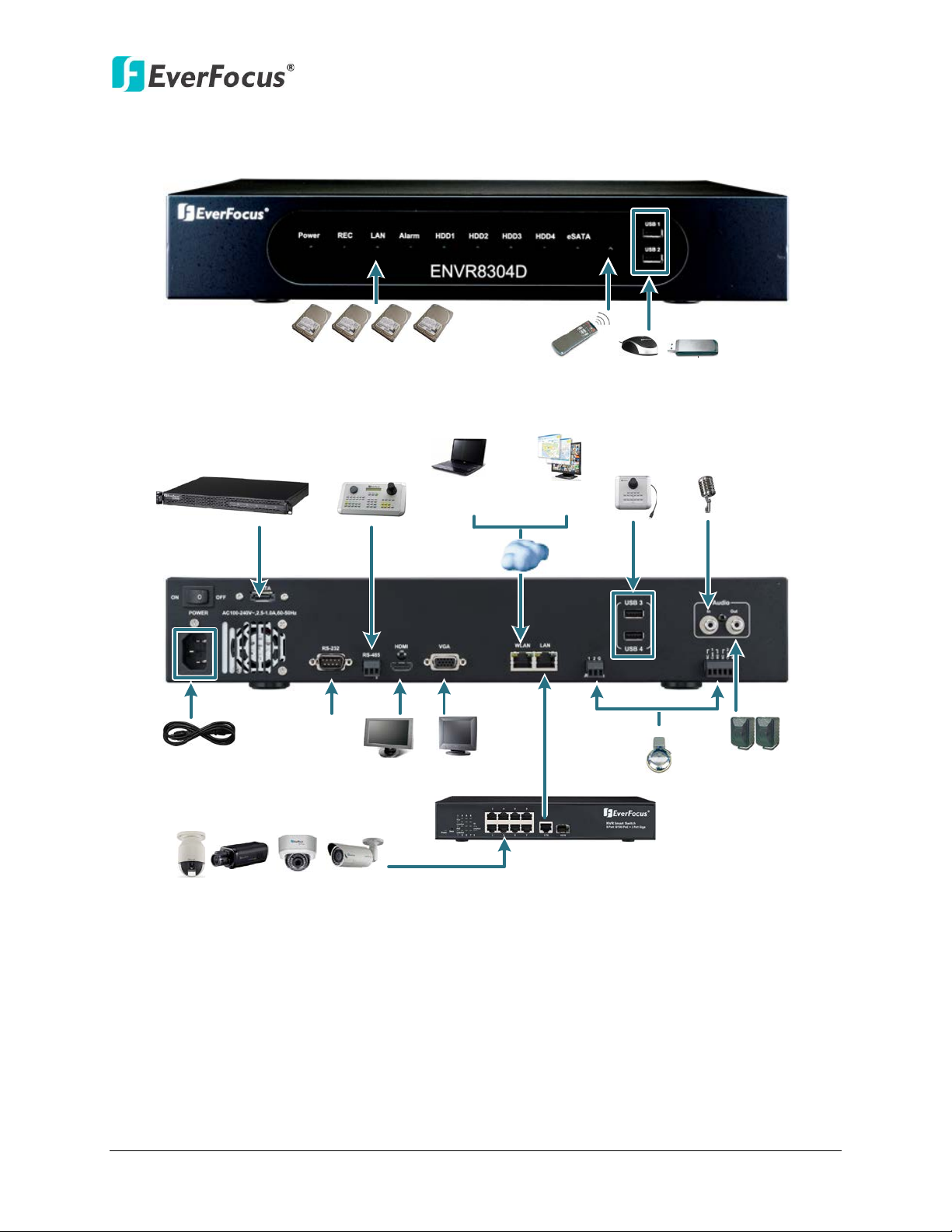
1.1 Overview
Mouse
USB Memory Stick
IR Remote Control
Front View
Rear View
Power Cord
eSATA HDD
Expansion
(EDA450)
RS-485
Device
RS-232
Data Input
Line Level
Audio In
Line Level
Audio Out
Alarm In / Out
Main Monitor
(HDMI)
Main Monitor
(VGA)
Web Remote
Client
PowerVideo Plus
(CMS)
NVR Smart Switch
EKB200
Keyborad
IP Cameras 1 ~ 8
Network
ENVR8304D-8CH
Figure 1-1
2
Page 12

ENVR8304D-8CH
1.2 Features
• 8-channel real-time recording and playback at 1080p resolution
• Support megapixel IP cameras
• The Plug and Play design simplifies installation and configuration
• H.264 compression format for enhancing recording capacity and improving network
image transmission speed
• Separately configured HDMI or VGA (1080p) monitor outputs
• High bandwidth 1080p recording (200 / 240fps) with recordable reduced bandwidth
stream for mobile or multiplexed viewing applications
• RAID5 – for full data protection
• Free EverFocus DDNS Service – static IP address is not required for reliable remote access
• Supports one eSATA port for external HDD (optional:EDA450)
• Supports live monitoring and playback of video from mobile devices via MobileFocus /
MobileFocus Plus Apps
• Multiple control inputs: mouse / remote controller / EKB500 and EKB200 keyboards
• Multiple intelligent video query functionality, including snapshot and smart search
• Powerful archive functionality from both remote and NVR sites
• Simplified access to common features such as setup, archival, playback and search
functions through express menus
• Remote configuration support from built-in web interface
• Gigabit Ethernet interface for remote network viewing and control
• 8 ports PoE smart switch (NVR Smart Switch)
• Integration with PowerVideo Plus
• Multi-language support
• 19” Rack mountable – rack ears included
3
Page 13
ENVR8304D-8CH
•
•
•
•
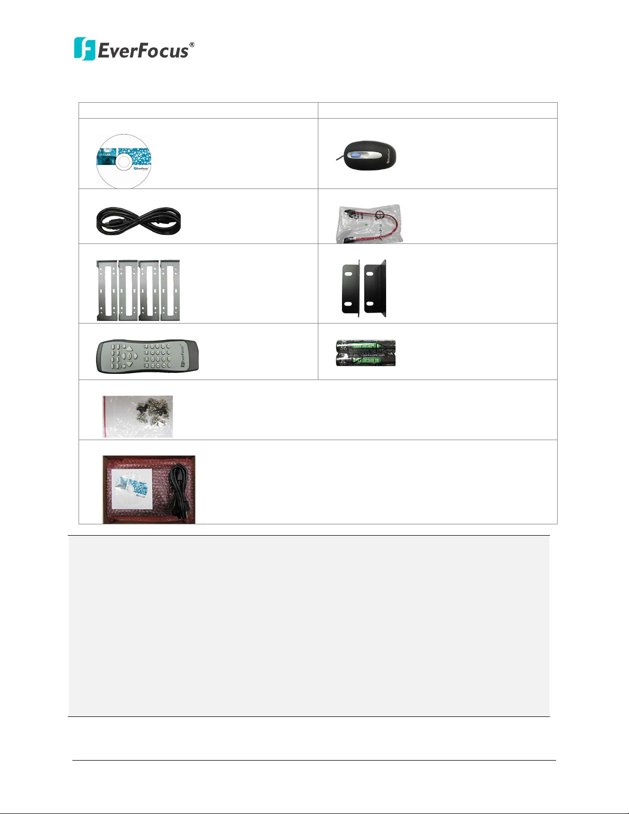
• Power Cord x 1
• SATA Cable x 4
•
•
• IR Remote Control x 1
• AAA Battery x 2 (Please see Note 4.)
•
• NVR Smart Switch x 1, Power Cord x 1, CD x 1 (Please see Note 5.)
Note:
1.3 Packing List
ENVR8304D-8CH x 1
CD x 1 (Please see Note 3.)
HDD Bracket x 4
Sliver Screw x 16, Washer Head Screw x 8, M3 (φ6.8) Screw x 4
User Manual x 1
Mouse x 1
Rack Ear x 2
1. Equipment configurations and supplied accessories vary by country. Please consult your
local EverFocus office or agents for more information. Please also keep the shipping
carton for possible future use.
2. Contact the shipper if any items appear to have been damaged in the shipping process.
3. The CD contains the IP Utility software, User Manual and Quick Installation Guide.
4. Risk of explosion if battery is replaced by an incorrect type. Dispose of used batteries
according to the instructions.
a. Use only two AAA dry cell batteries.
b. Do not dispose of the batteries in a fire as it may explode.
5. These three items are packed in a box, and the CD contains the User Manual of the NVR
Smart Switch.
4
Page 14
ENVR8304D-8CH
•
•
•
1.4 Optional Accessories
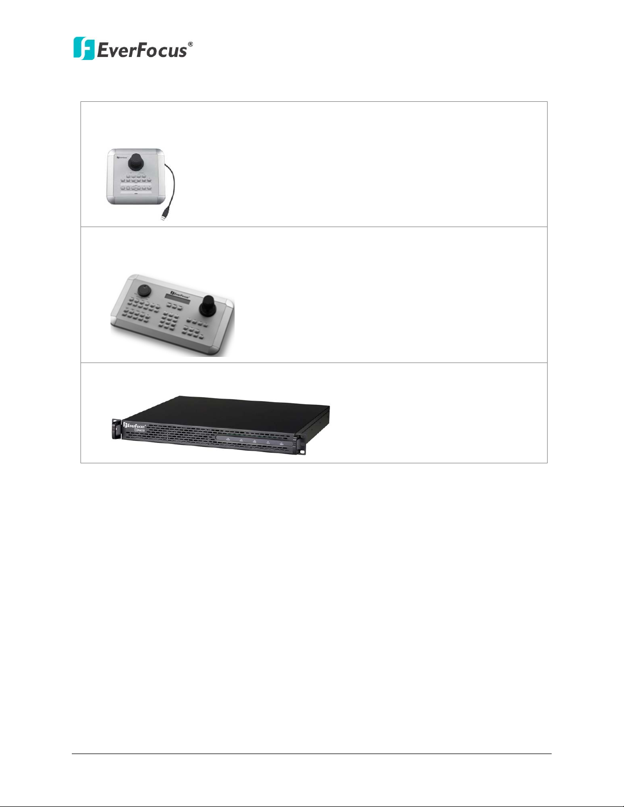
EKB200 (USB controller keyboard: connect to the PC to control the PTZ cameras
connected to the NVR). Please refer to 6.8.6 EKB200 Setting and the User Manual of
the EKB200 Keyboard.
EKB500 (RS-485 keyboard: connect to the RS-485 port to control the PTZ cameras
connected to the NVR). Please refer to 6.1 Camera and the User Manual of the EKB500
Keyboard.
EDA450 (eSATA Storage Device: connect to the eSATA port of the ENVR8304D-8CH).
Please refer to No. 2, Figure 1-3.
5
Page 15
ENVR8304D-8CH
51 6 7 8
2 3 4
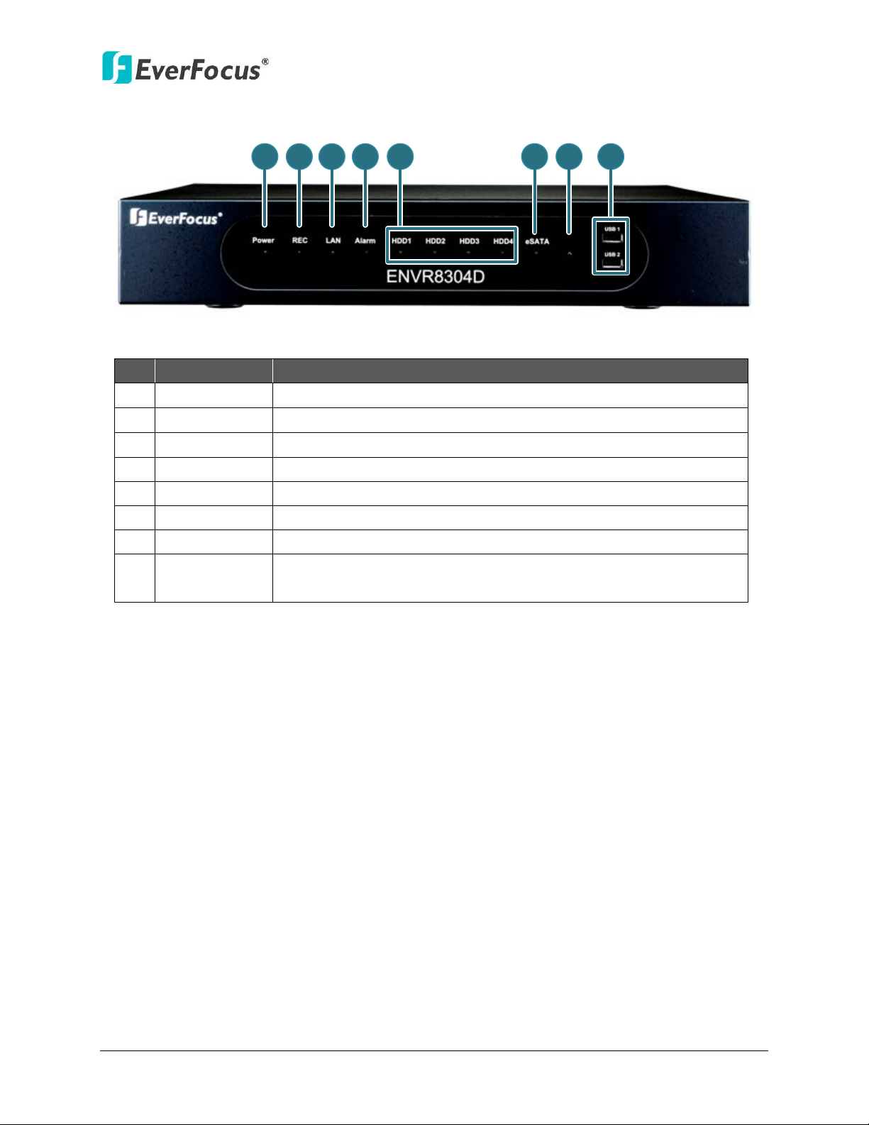
1.5 Front Panel
Figure 1-2
No. Name Description
1 Power Indicates the power is on.
2 REC Indicates the NVR is recording.
3 LAN Indicates the NVR is connected to the network.
4 Alarm Indicates an alarm input is triggered.
5 HDD1~4 Separately indicates the internal HDD 1~4 is activating.
6 eSATA Indicates the external HDD is activating.
7 IR Receiver Receiver for signals from the IR remote control.
8 USB1 / USB2
USB2.0 ports for connecting to a mouse, external storage device,
or EKB200 keyboard.
6
Page 16
ENVR8304D-8CH
1
2
3
4
5
6
7
8
9
10
11
13
14
12
Connects to the 100-240 VAC~ power using the supplied Power
Connects to the RS-485 device, such as EverFocus’ EKB-500
Connects to the Main monitor using a HDMI cable. Please refer to
Connects to the Main monitor using a VGA cable. Please refer to
Connects to the network using a standard RJ-45 CAT5 10/100Mb
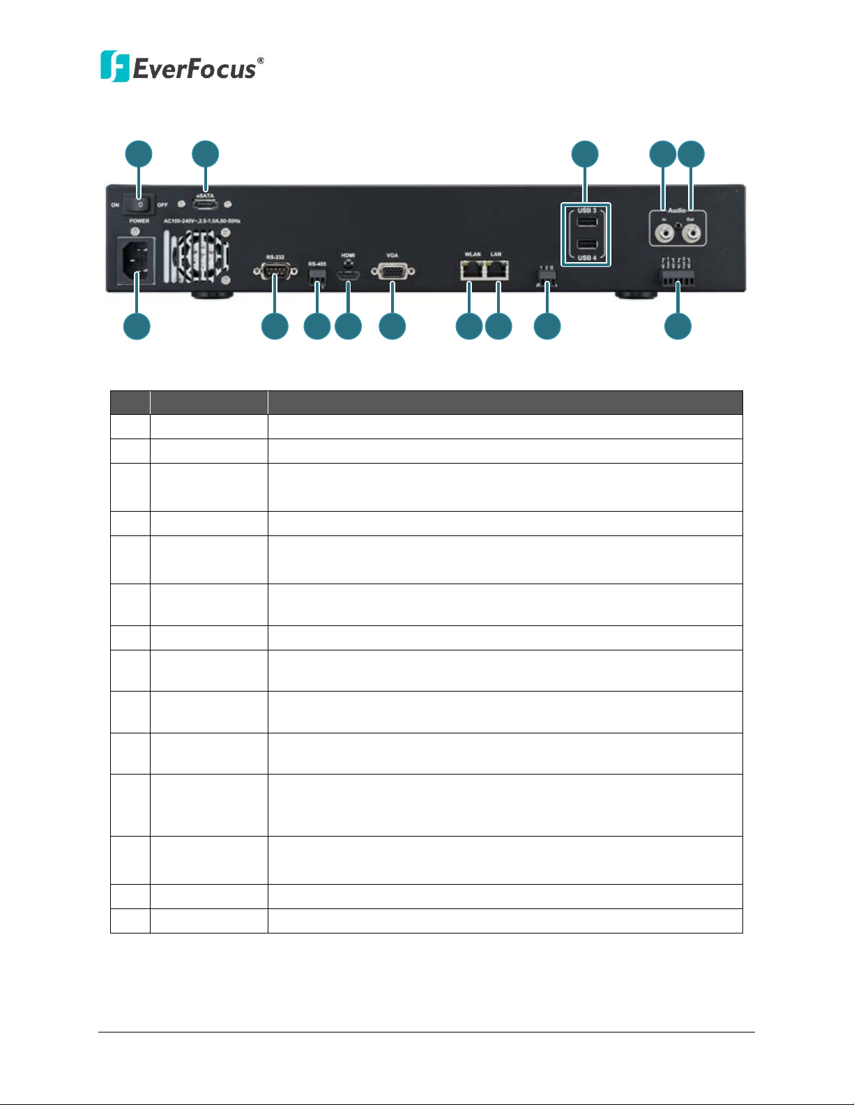
1.6 Rear Panel
Figure 1-3
No. Name Description
1 Power Press to turn On / Off the NVR.
2 eSATA Port Connects to an external eSATA storage device. (EDA450)
3 USB3 / USB4
4 Audio Input Connects to the audio input devices.
5 Audio Output
6 Power Port
7 RS-232 Port Connects to the RS-232 device. Please refer to 2.3.7 RS-232 Port.
8 RS-485 Port
9 HDMI Port
10 VGA Port
11 WLAN
12 LAN
The USB2.0 ports for connecting to a mouse, external storage
device or EKB200 keyboard.
Connects to the audio output devices, such as speakers. Note that
the speakers with amplifier are required.
Cord.
keyboard. Please refer to 2.3.6 RS-485 Port.
2.3.3 Monitor Connection.
2.3.3 Monitor Connection.
Ethernet cable. Please refer to 2.5 Connecting the NVR to the
Network.
Connects to a PoE device using a standard RJ-45 CAT5 10/100Mb
Ethernet cable. Please refer to 2.3.1 Camera Connection.
13 Alarm Input Connects up to 2 alarm inputs. Please refer to 2.3.5 Alarm IO.
14 Alarm Output Connects to 2 alarm output devices. Please refer to 2.3.5 Alarm IO.
7
Page 17
ENVR8304D-8CH
Silver Screw
HDD Bracket
2
2. Installation
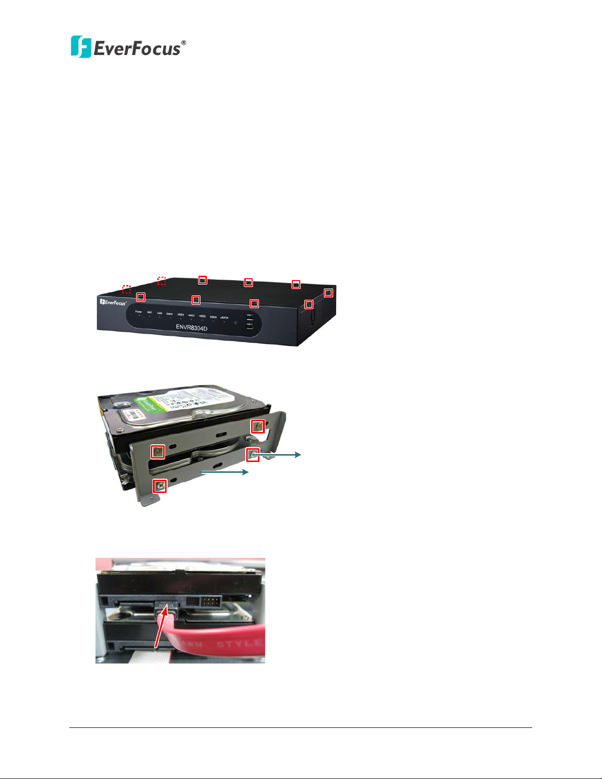
2.1 Hard Disk Drive Installation
1. Make sure the NVR is power-off.
2. Unscrew the ten housing screws on the NVR, and open the housing.
Chapter
Figure 2-1
3. Screw two HDD brackets on both sides of the HDDs using the Sliver Screws.
Figure 2-2
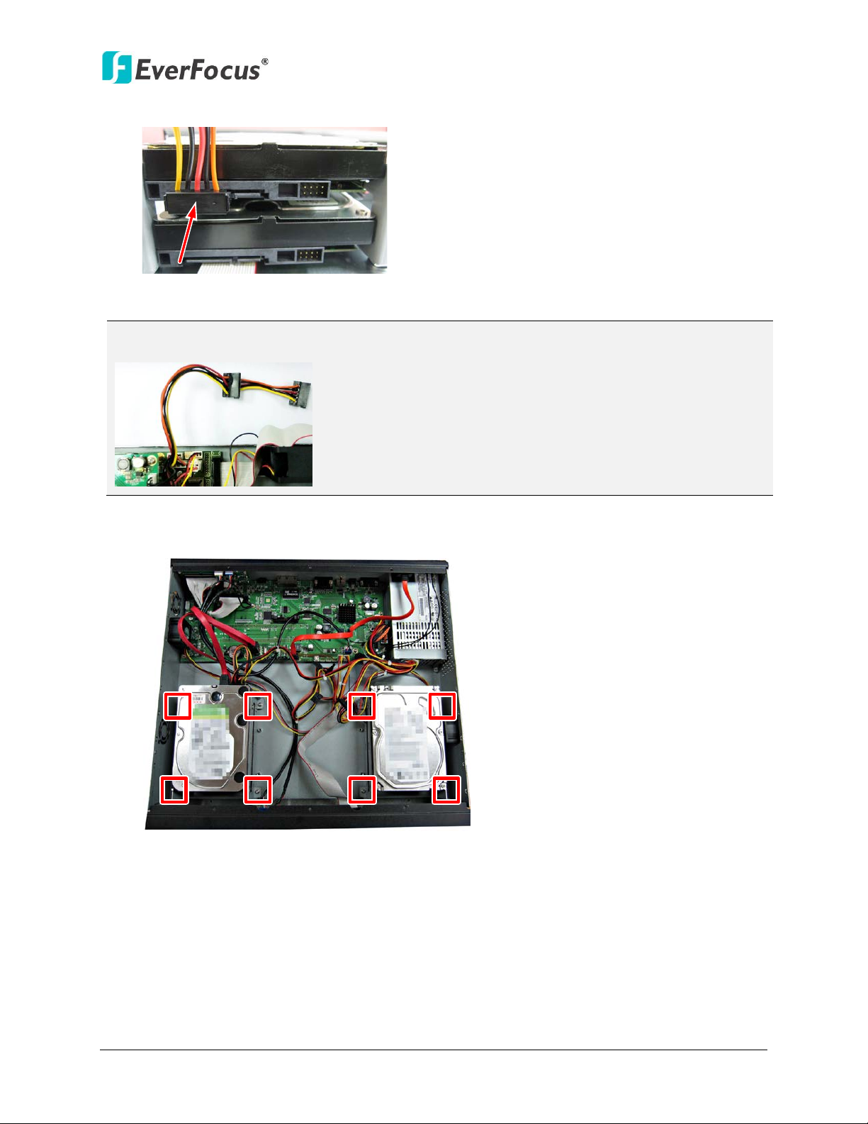
4. Use the SATA Cable, and connect one end to the SATA port on the small PCB inside the
NVR, and the other end to the SATA port on the HDD.
Figure 2-3
8
Page 18
ENVR8304D-8CH
Note: The internal power cable is connected to the Main board inside the NVR. The power
5. Connect the internal power cable to the HDD.
Figure 2-4
cable features two connectors, which can be used to connect to two HDDs.
6. Screw the HDDs with the brackets inside the NVR using the Washer Head Screws.
Figure 2-5
7. Screw back the housing to the NVR.
9
Page 19
ENVR8304D-8CH
SATA Hard Disk
Model
Capacity
SV35.5 SATA2 / ST3500410SV
500GB
SV35.5 SATA3 / ST3500411SV
500GB
SV35.5 SATA3 / ST31000526SV
1TB
SV35 SATA3 / ST2000VX002
2TB
Barracuda SATA3 / ST500DM002
500GB
Barracuda SATA3 / ST1000DM003
1TB
WD10EVDS SATA2
1TB
WD10EURS SATA2
1TB
WD20EVDS SATA2
2TB
WD20EURS SATA2
2TB
WD1600AVVS SATA
160GB
WD3200AVVS SATA
320GB
WD5000AVVS SATA
500GB
WD7500AVVS SATA
750GB
WD10EVVS SATA
1TB
2.1.1 Hard Disk Compatibility List
Please use the hard disk models recommended in the list below to ensure your hard disks will
be compatible.
SV35.5 SATA2 / ST31000525SV 1TB
Seagate
Western Digital
Note: If using two or more hard disks, please choose the hard disks with the same capacity.
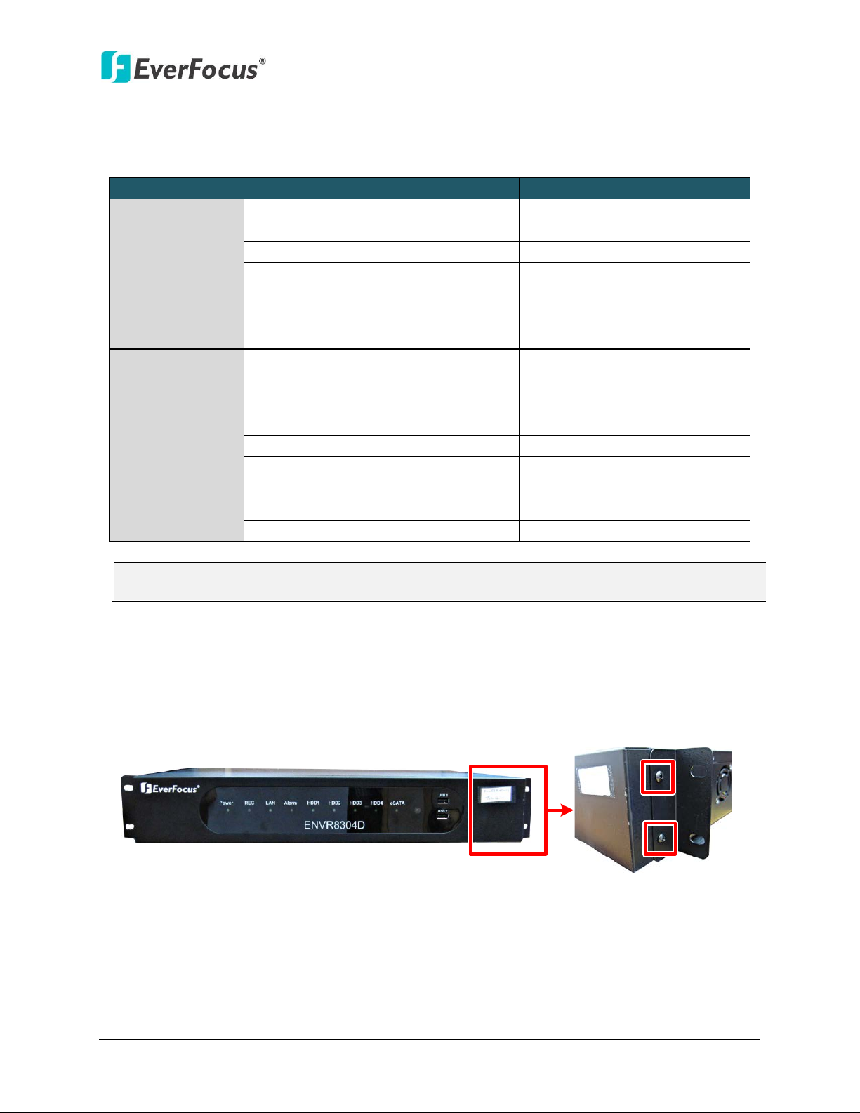
2.2 Rack Mount
To install rack ears on the NVR, use the supplied two Rack Ears and the four M3 (φ6.8) Screws
for rack mount installation on both side.
Figure 2-6
10
Page 20
ENVR8304D-8CH
Power Supply
Line Level
Audio In
Line Level
Audio Out
Main Monitor
(
HDMI)
Main Monitor
(VGA)
Web Remote
Client
PowerVideo
Plus
(CMS
)
NVR Smart Switch
Mouse &
EKB200 Keyboard
IP Cameras 1 ~ 8
Network
EVNR8304D-8CH
1
2
3
4
5
6
7
8
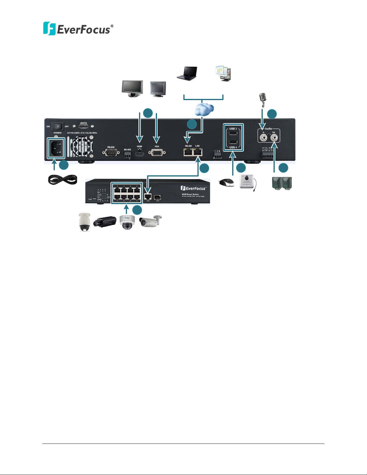
2.3 Basic Connection
The instructions below describe the basic connection for ENVR8304D-8CH
Figure 2-7
1. Using the supplied Power Cord, connect one end to the 100-240 VAC~ port on the NVR and
the other end to the 100-240 VAC~ power outlet.
2. To view videos, connect a monitor to the HDMI or VGA port using the HDMI or VGA cable
supplied by the monitor manufacturer.
3. To manage the NVR over network, use a standard RJ-45 CAT5 10/100Mb Ethernet cable to
connect the WLAN port of the NVR to the network. Please refer to 2.5 Connecting the NVR to
the Network.
4. Connect the LAN port of the NVR to a PoE device using a standard RJ-45 CAT5 10/100Mb
Ethernet cable. Please see 2.3.1 Camera Connection for more details.
5. Connect the IP cameras to the 1~8 camera ports at the rear of the PoE switch using Ethernet
cables without separate power sources. Please see 2.3.1 Camera Connection for more
details.
6. Optionally connect a mouse or a keyboard (EKB200) to the NVR to control the system. You
can also control the system using the supplied IR Remote Controller.
7. Connect the audio input devices to the NVR.
8. To listen to audio of video source, connect speakers to the Audio Out port. Note that
speakers with amplifier are required.
11
Page 21
ENVR8304D-8CH
NVR Smart Switch
IP Cameras 1 ~ 8
EVNR8304
D
-8
CH
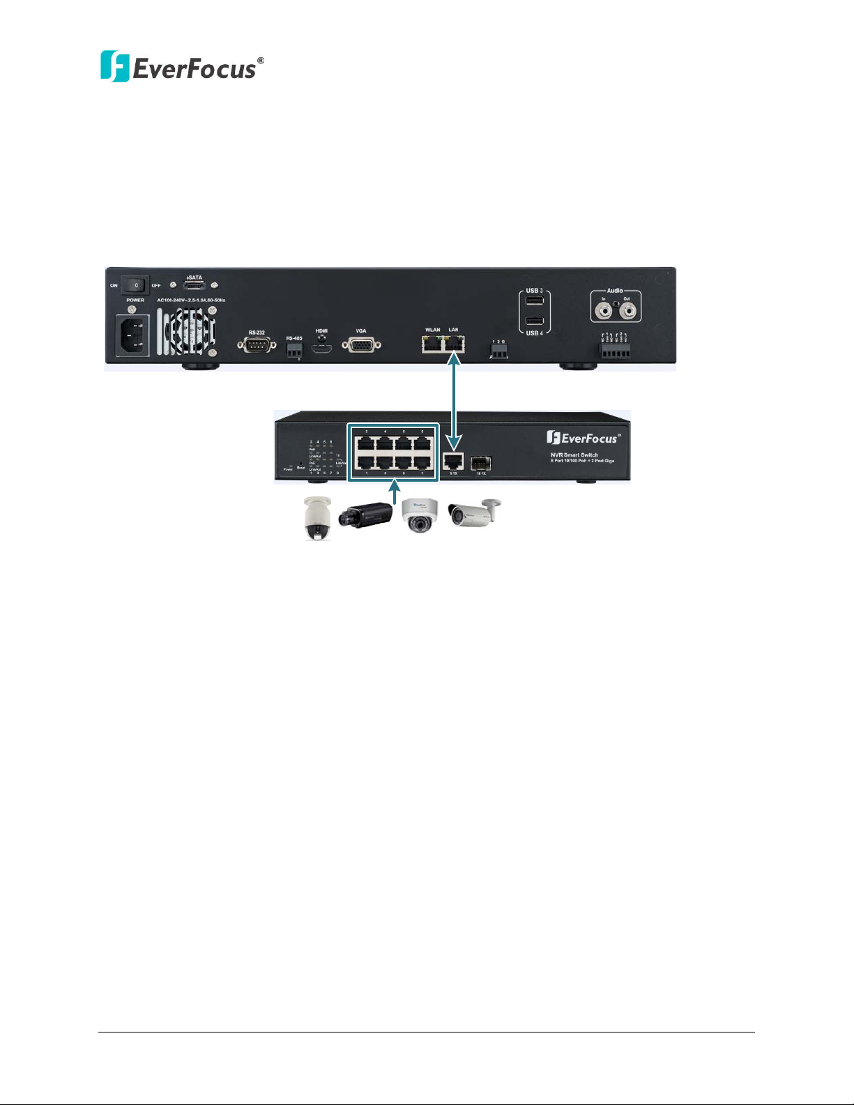
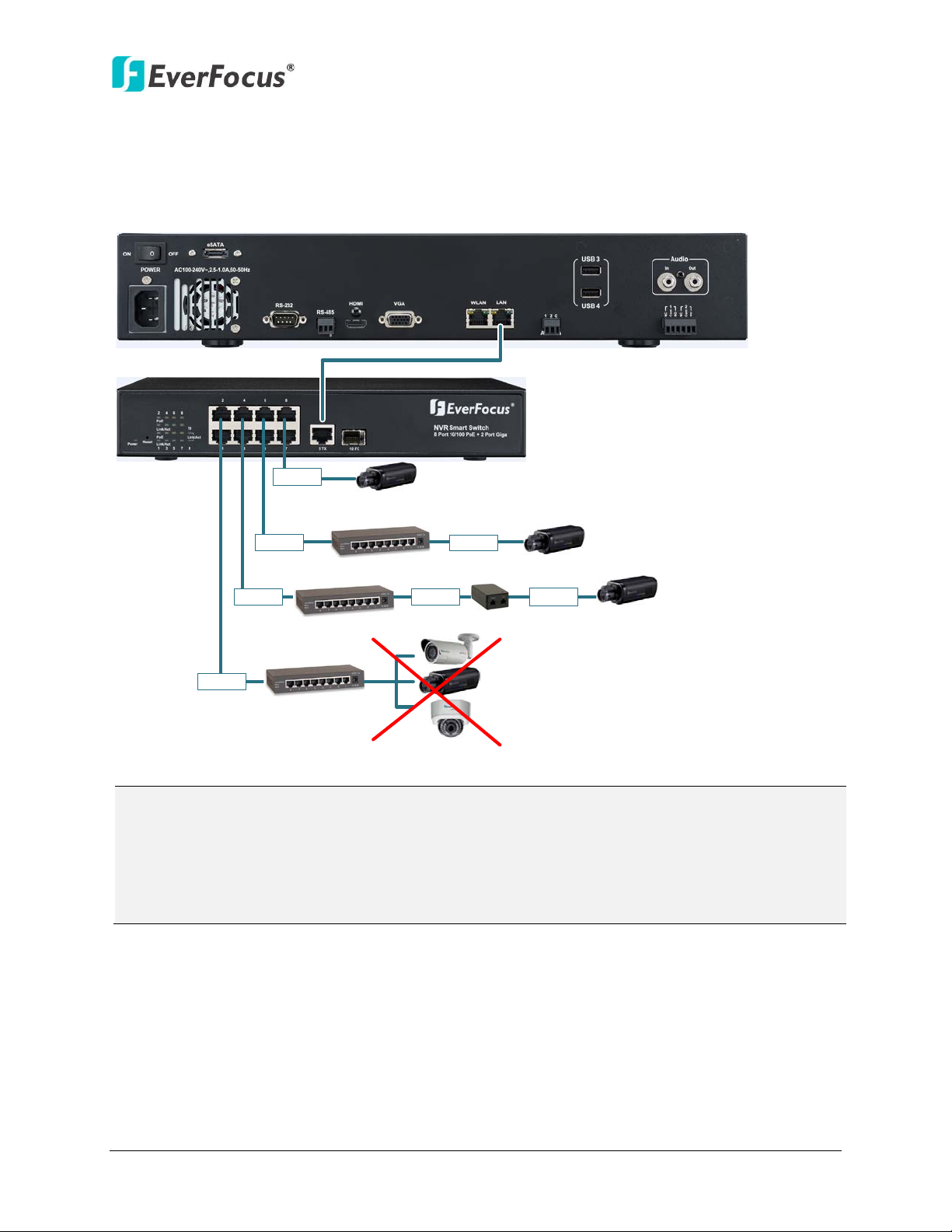
2.3.1 Camera Connection
Connect the LAN Port of the NVR to the Port 9 of EverFocus’ NVR Smart Switch using a RJ45
CAT5 10/100Mb Ethernet cable.
Connect the IP cameras to the 1~8 camera ports at the rear of the PoE switch using Ethernet
cables. If the length between the PoE switch and the IP camera exceeds 100 meters, please see
2.3.2 Cable Length Extension for cable length extension instruction.
Figure 2-8
12
Page 22
ENVR8304D-8CH
EVNR8304D-8CH
NVR Smart Switch
Hub
Hub
Hub
100 M
100 M
100 M
100 M
100 M
100 M
100 M
PoE Injector
The camera requires
separate power supply.
Connect to one camera
only.
Note:
3. Please refer to the User’s Manual of NVR Smart Switch for detailed information.
2.3.2 Cable Length Extension
The Ethernet connection is effective within 100 meters in distance. If the distance between the
PoE switch and the IP cameras is over 100 meters, you need to use a hub, PoE injector or PoE
extender, which should be connected to one camera only.
Figure 2-9
1. It is required to provide power supply additionally for the camera connecting by a hub for
extension.
2. For stable connection and operation, the user should establish a dedicated communication
line for IP cameras in the same network so that the router connection is not allowed.
13
Page 23
ENVR8304D-8CH
Main Monitor
(VGA)
Main Monitor
(
HDMI)
VGA Cable
HDMI Cable
Note:
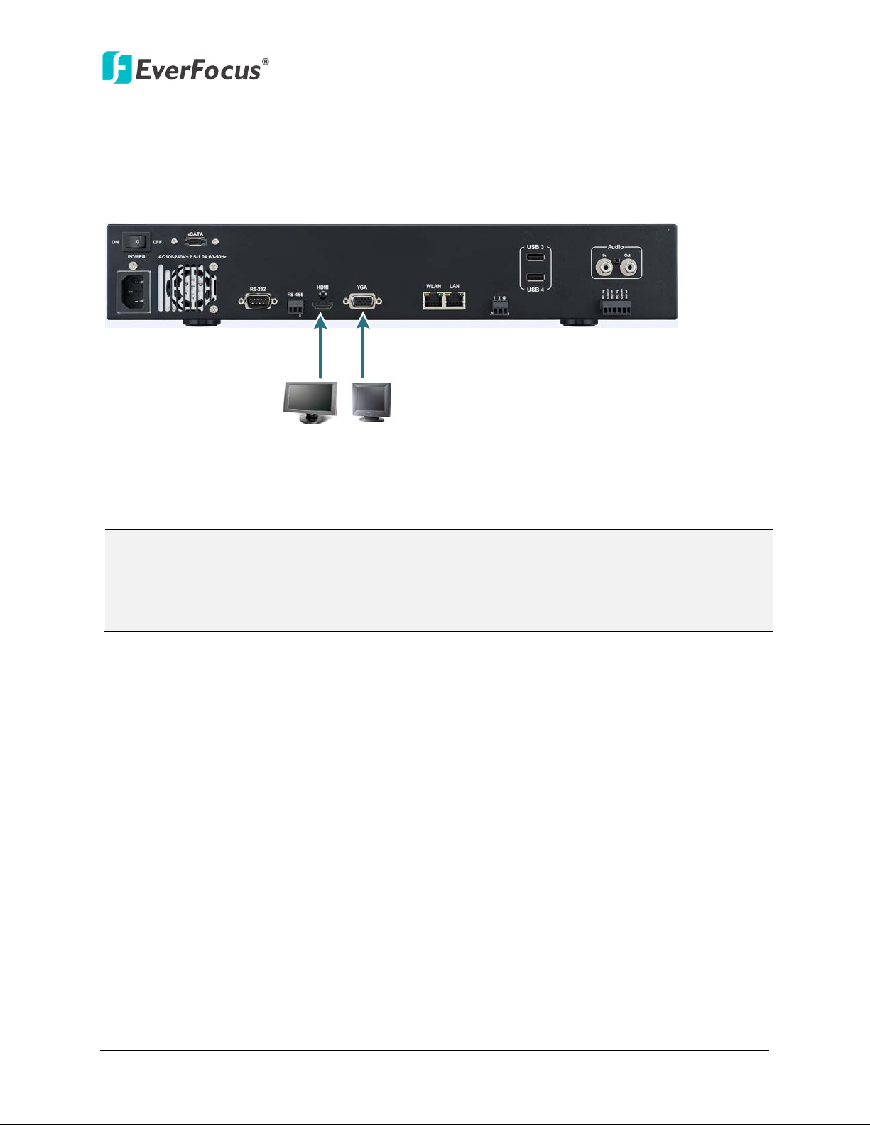
2.3.3 Monitor Connection
The NVR provides 2 main monitor outputs with identical functionality - VGA and HDMI. You can
connect the monitor to the VGA or HDMI port on the rear panel of the NVR. Both of the VGA
and HDMI video outputs can be used simultaneously and deliver full HD resolution (1920 x 1080,
progressive, 60 Hz. Vert., 68 KHz hor.).
Figure 2-10
1. The connected monitors’ specifications must comply with the resolution requirements.
2. Do not exceed the max. HDMI cable length of 15 meters.
3. The standard HDMI cables can support cable length up to 3 meters. For longer distances, such
as 15 meters, it is highly recommended to use high quality HDMI cables.
14
Page 24
ENVR8304D-8CH
Screen Mode: 1920x1080 (16:9)
Camera Ratio: 16:9
Camera Ratio: 4:3
Screen Mode:
800
x600 /
1024x768 /
1280x1024 (4
:3
)
Camera Ratio: 16
:
9
Camera Ratio:
4:3
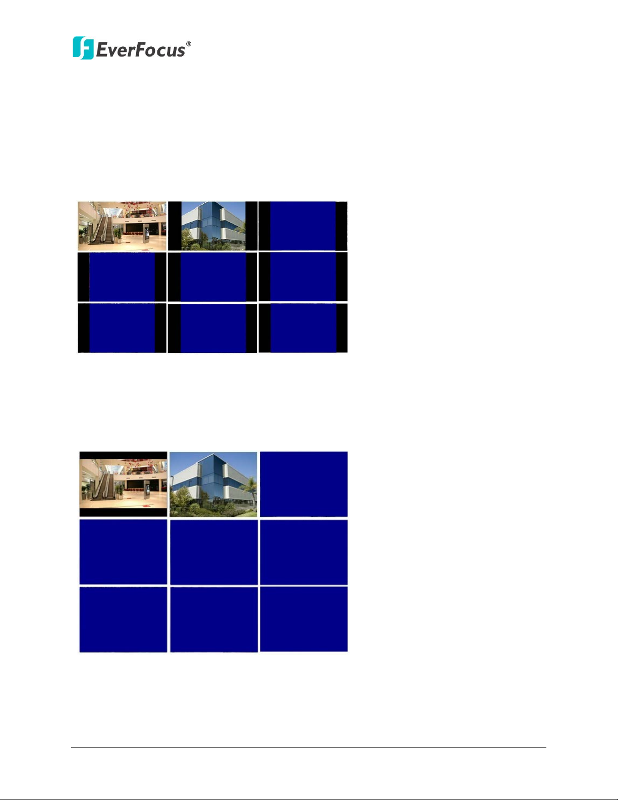
2.3.4 Display Aspect Ratio
It is recommended to select the same ratio of the screen resolution and the camera live view
display to avoid black bars showing on the live view screen as the images below.
If you select 1920x1080 (16:9) screen resolution in the Screen Mode drop-down list (see 6.5.1
Monitor OSD), it is recommended to also change the camera live view display to 16:9 aspect
ratio in the Ratio drop-down list (see 6.1.6 Adjust).
If selecting 800x600, 1024x768 or 1280x1024 (4:3) screen resolution in the Screen Mode
drop-down list (see 6.5.1 Monitor OSD), it is recommended to also change the camera live view
display to 4:3 aspect ratio in the Ratio drop-down list (see 6.1.6 Adjust).
Figure 2-11
Figure 2-12
15
Page 25
ENVR8304D-8CH
Alarm In Alarm Out
No.
Description
No.
Description
1
ALM_IN1
2
ALM_IN2
ALMIN
GND
ALMIN
GND
Alarm Input with N.O. contact in idle state Alarm Input with N.C. contact in idle state
ALMOUT +
ALMOUT
-
ALMOUT +
ALMOUT
-
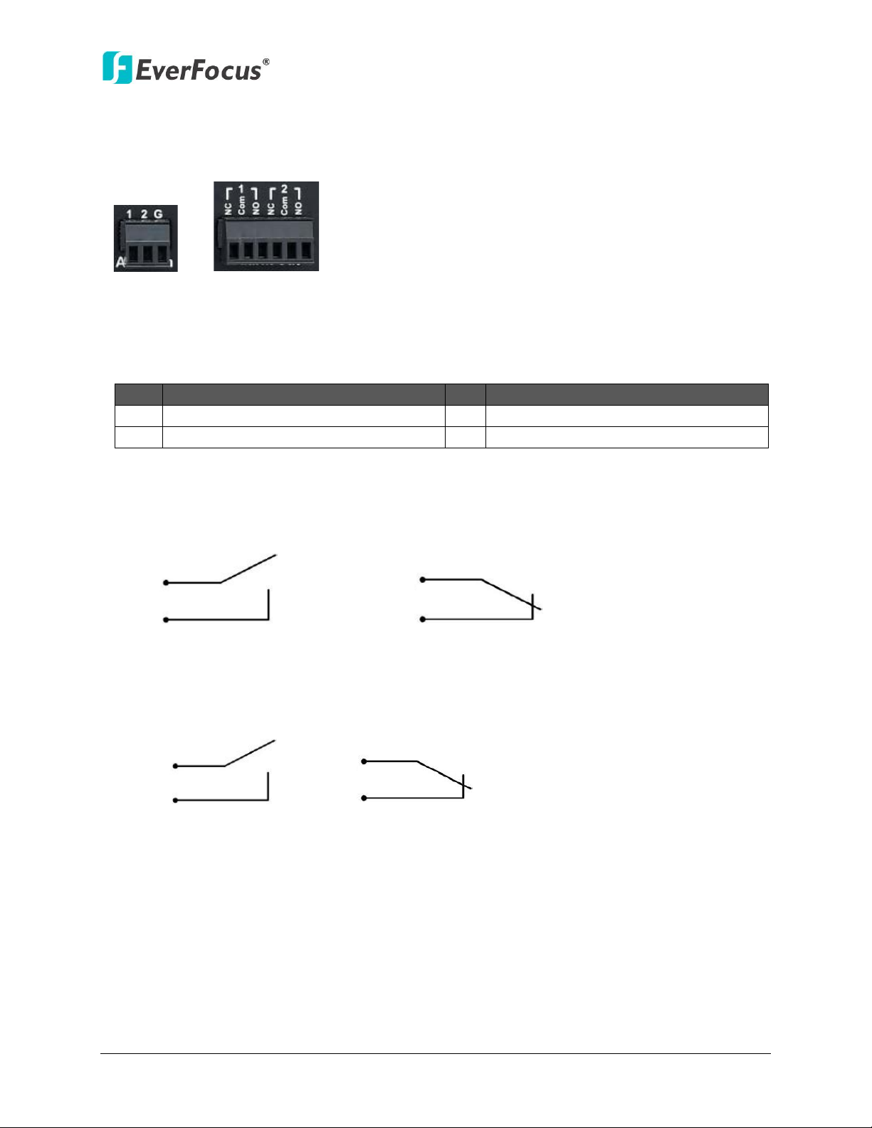
2.3.5 Alarm I/O
The NVR provides two alarm inputs and two alarm outputs. Please refer to the table below for
PIN assignment.
Figure 2-13
Alarm Input
G GND
Alarm Input Contacts
This NVR provides one alarm input per camera. All inputs are programmable N.O. (Normal Open)
or N.C. (Normal Closed). All settings are programmed in the ALARM / Event menu.
Alarm Output Contacts
The relay output provides either Normally Open or Normally Closed dry contacts.
16
Page 26
ENVR8304D-8CH
+ - G
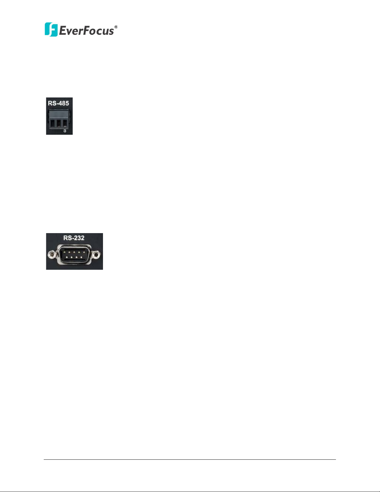
2.3.6 RS-485 Port
The RS-485 port, located on the rear panel of the NVR, can be used to connect to an RS-485
keyboard, such as EverFocus’ EKB500, for controlling NVR and HD PTZ cameras. For details on
the RS-485 configurations on the NVR, please refer to 6.8.5 I/O Control. The RS-485 pin
assignment is as follows:
Figure 2-14
2.3.7 RS-232 Port
The RS-232 port, located on the rear panel of the NVR, can be used to connect to an RS-232
data input device such as POS system. The RS-232 port of the NVR is a 9 pin D-Sub socket. For
details on the RS-232 configurations on the NVR, please refer to 6.8.5 I/O Control.
Figure 2-15
2.4 Turning On / Off the Power
Before powering on the NVR, please make sure the internal HDDs have been installed properly.
When you have completed the basic cable connections, you are ready to turn on the NVR.
Once connect the supplied Power Cord to the power outlet, the NVR will be powered on. All of
the LED indicators on the front panel will light up for a second, but the Power and REC LED will
remain light up. After hearing 1 beeps from the NVR, you can start operating. To turn off the
power, simply unplug the Power Cord from the power outlet. You can also press the Power
button on the rear panel to turn on and off the NVR without unplugging the Power Cord.
17
Page 27
ENVR8304D-8CH
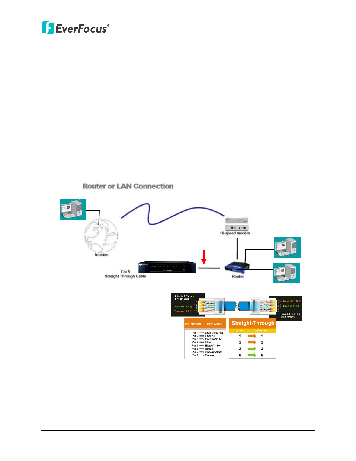
Straight-through LAN patch cable
Right: Pinout of a straight-through cable.
2.5 Connecting the NVR to the Network
There are three methods to connect the NVR to the network: Router or LAN Connection, Direct
High‐Speed Connection and One‐to‐One Connection. For more information of the network,
please refer to Appendix A. Network Overview.
2.5.1 Router or LAN Connection
This is the most common connection in which the NVR is connected to a router and allows
multiple users on and off site to see the NVR on a LAN/WAN (Internet). The NVR must be
assigned an IP address that is compatible with its LAN. By setting up port forwarding on the
router, you can remotely access the cameras from outside of the LAN via the Internet. To
remotely access the Web interface, please refer to 7. Remote Access to the NVR. To set up
port forwarding, please consult the manual of the router or refer to Appendix B: Linksys &
D-Link Port Forwarding.
Figure 2-16
18
Page 28
ENVR8304D-8CH
Connection Procedure:
The First step is to purchase or make a straight through cable. We recommend
purchasing one if you have never made a straight through cable. Please remember
you can not use a cross-over network cable for this application.
Once you have a straight through cable, plug one end into the LAN port on the back
of the recorder and the other into the router.
Log into the EverFocus NVR menu and go to the Network Setting Menu.
To let the router automatically assign an address:
Set the Network Type to DHCP. Make sure to write down the IP address and the
Gateway.
Exit from the Menu to save settings.
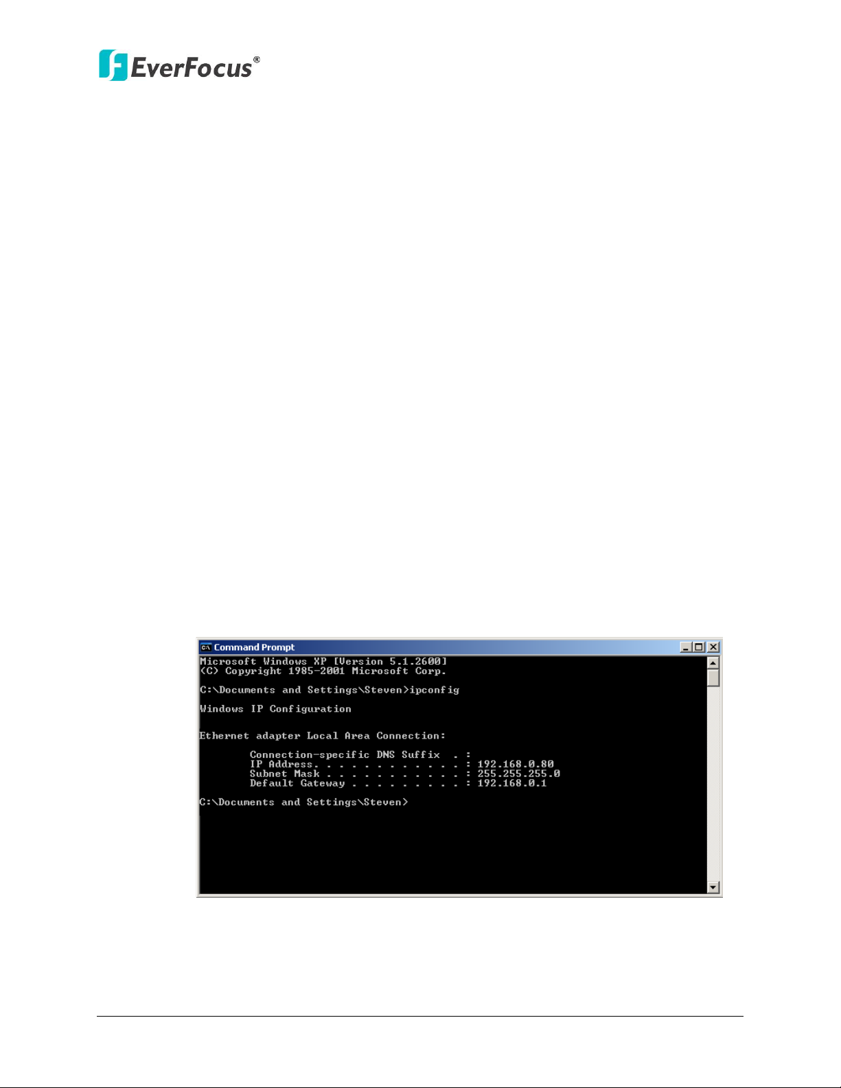
To manually assign an address:
Go to a computer connected on the same network as the NVR.
Click on the Start button and choose Run.
If using Windows Vista, choose Search instead.
Type “command” and click on OK.
In Vista, you will need to double-click on the “Command Prompt” file to open it.
In the DOS prompt, type “ipconfig” and press Enter.
The network information will be displayed on a screen similar to the one below.
In Windows Vista, look for the information that says “IP v4”.
F igure 2-17
19
Page 29

ENVR8304D-8CH
Note: The NVR’s IP address will only work at the location of the NVR. To connect
Note: If you changed to a different port other than 80, you will need to include this
Take the values for Subnet Mask and Default Gateway and input them into the
NVR; these values should be exactly the same in both devices. However, you
should change the last number of the IP address. For example, if the IP address
of the computer is 192.168.2.101, the NVR’s IP address should be 192.168.2.50.
To access the NVR from a computer simply open Internet Explorer and in the address
bar type:
http:// (IP address of the NVR)
from a different location over the Internet, see below.
To set the NVR for Internet Connection through router:
The next step is to open ports within your router. Log into the router using a PC and
open the following ports.
Ports to open: 80
If your Internet service provider blocks port 80, you can change it to a different
port in the NVR’s Network Menu Setup; open/forward that port instead.
If you are using a Linksys or D-Link router, see Appendix B for basic support on
setting up ports. For any other router, you will need to contact the manufacturer
for support.
To access the NVR from a computer simply open Internet Explorer and in the address
bar type:
http:// (the IP address given by your internet service provider)
at the end of the IP address:
http:// (the IP address given by your internet service provider):port number
If you have a WAN Dynamic IP address and have opened the ports, go to 6.7.3 DDNS
Setup to configure the DDNS settings.
20
Page 30
ENVR8304D-8CH
Note: If you have a dynamic IP address, you can set the NVR to DHCP to automatically
Note: When using this type of connection, only one device can be connected to the
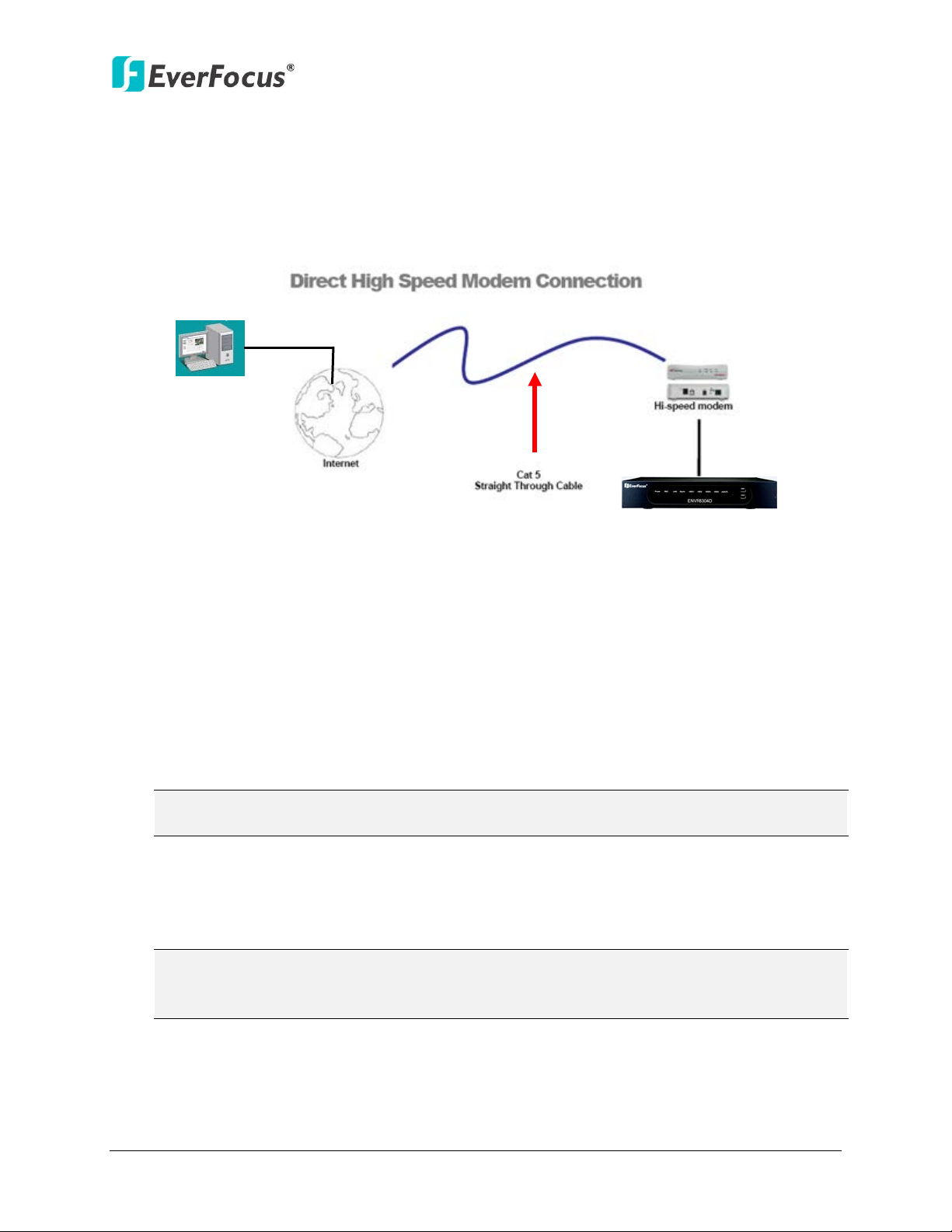
2.5.2 Direct High-Speed Connection
In a Direct High-Speed Connection, the NVR connects directly to a modem without the
need for a router. You need to set the static or dynamic WAN IP address assigned by your
ISP (Internet Service Provider) in the NVR’s configuration web pages. To access the NVR,
just type “http://xxx”, where xxx is the IP address given by your ISP. If you have a dynamic
IP address, this connection may require that you use DDNS for a reliable connection.
Figure 2-18
Connection Procedure:
The first step is to purchase or make a straight through cable. We recommend
purchasing one if you have never made a straight through cable. Please remember
you can not use a cross-over network cable for this application
Once you have a straight through cable plug one end into the LAN port on the back of
the recorder and the other into the high speed modem.
Log into the EverFocus NVR menu and go to the Network Setting Menu.
Input the Static IP address, the Subnet Mask, and the Gateway that you obtained
from the internet service provider.
detect the network settings. Therefore, it can use a dynamic IP address.
Exit from the NVR’s Menu to save the settings.
To access the NVR from a computer, open Internet Explorer and in the address bar
type: http:// (IP address given by your internet service provider)
modem at a time. You will need to use a computer at a different location to test the
connection s.
21
Page 31
ENVR8304D-8CH
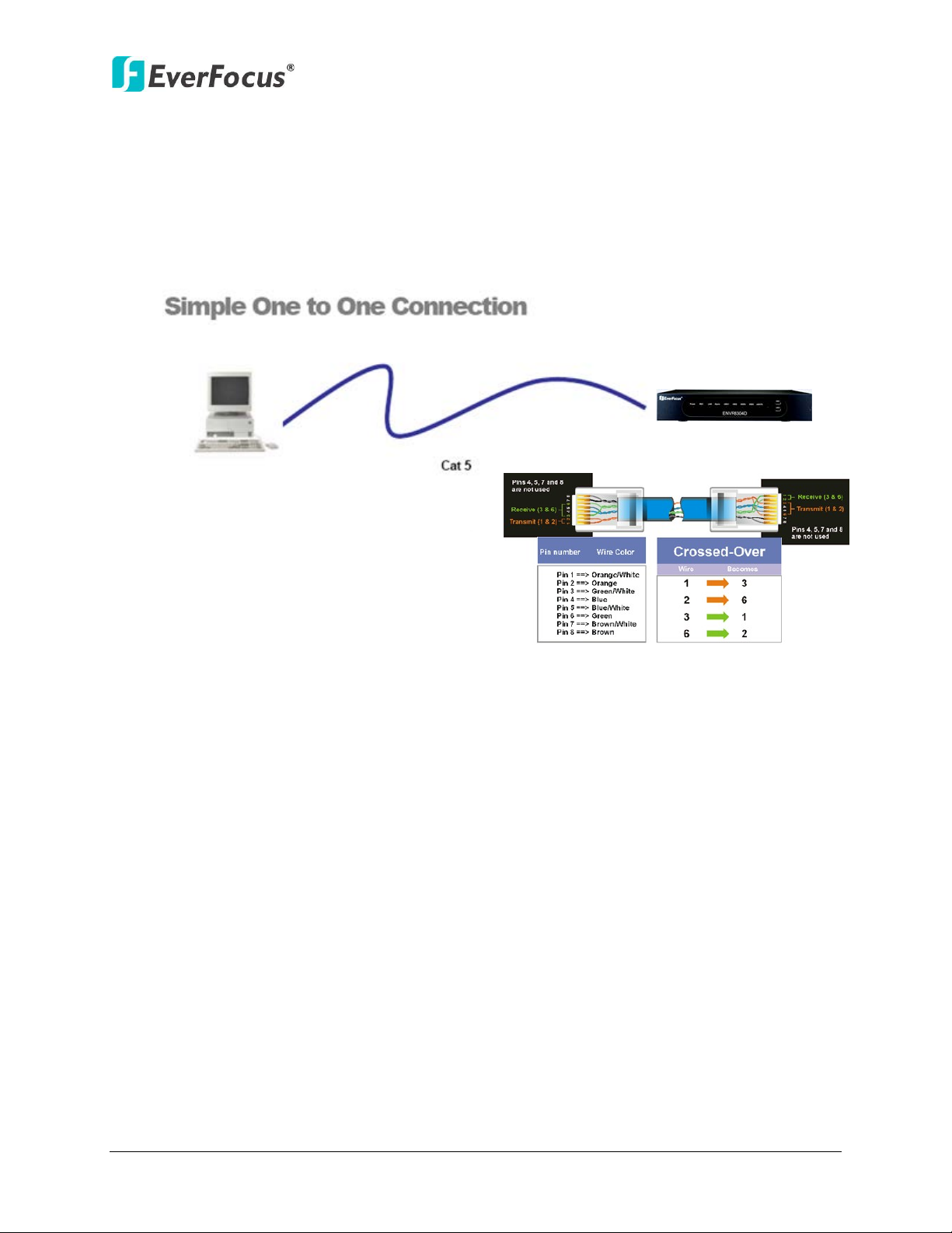
Right: Pinout of a crossed-over cable.
2.5.3 One-to-One Connection
You can connect directly without using a switch, router or modem. However, only the PC
connected to the NVR will be able to view the NVR. You will also have to manually assign a
compatible IP address to both the computer and the NVR. Unless the PC has another
network connection, the NVR will be the only network device visible to the PC. See the
diagram below:
Figure 2-19
Connection Procedure:
The First step is to purchase or make a cross-over cable. We recommend purchasing
one if you have never made a cross-over cable. Please remember you can not use a
straight through network cable for this application.
Once you have a cross-over cable, plug one end into the LAN port on the back of the
NVR and the other into the network card on the back of the computer.
Log into the EverFocus NVR menu and go to the Network Setting Menu.
You must use the Static IP option for this type of connection.
Assign an IP of 192.168.001.003, a Subnet Mask of 255.255.255.000, and a Gateway
of 192.168.001.001. You can ignore DNS Server.
The next step is to set the computer’s network settings to match those of the NVR.
You will need Administrator privileges on your Windows machine to do this.
To assign a fixed IP address in Windows 2000/XP, follow the instructions below:
22
Page 32

ENVR8304D-8CH
Go to Start. Double-click on Control Panel.
Figure 2-20
Click Network and Internet Connection.
Figure 2-21
Click Network Connections.
Figure 2-22
23
Page 33

ENVR8304D-8CH
Right-click on Local Area Connection and select Properties.
Figure 2-23
Click on Internet Protocol (TCP/IP) and then click Properties.
Figure 2-24
Select Use the following IP address. Assign an IP address of 192.168.1.2, a
Subnet Mask of 255.255.255.0, and a Default Gateway of 192.168.1.1 and then
click OK.
Restart both of the computer and the NVR.
24
Page 34

ENVR8304D-8CH
To access the NVR from the computer, simply open Internet Explorer and in the
address bar type: http://192.168.1.3
Figure 2-25
Select Use the following IP address. Assign an IP address of 192.168.1.2, a
Subnet Mask of 255.255.255.0, and a Default Gateway of 192.168.1.1 and then
click OK.
Restart both of the computer and the NVR.
To access the NVR from the computer, simply open Internet Explorer and in the
address bar type: http://192.168.1.3
25
Page 35

ENVR8304D-8CH
2.6 Checking the Dynamic IP Address
You can look up the IP address and access the Web interface of the NVR using the IP Utility
(IPU) program, which is contained in the CD. It can also be downloaded from EverFocus’
Website: http://www.everfocus.com/tools.cfm. Please connect the NVR in the same LAN of your
computer.
1. Install and then start the IPU program . The following dialog box appears.
Figure 2-26
2. IPU will automatically search the IP devices connected in the LAN. The default network
values of the IP devices will be displayed. By default, the network protocol of the IP device
is DHCP.
3. To configure the network settings, select an IP device and then click Login/Multi Login.
Figure 2-27
26
Page 36

ENVR8304D-8CH
Note:
4. Type the user ID and password. Click OK.
1. The default user ID is admin and the default password is 11111111.
2. If you select more than one NVRs that have the same user ID / password, you will
be able to log in several NVRs at once.
5. To change the IP address, double-click the values in the column and type the numbers or
select an option. Click Set IP Address to save the settings.
Figure 2-28
Note: Most networks uses DHCP to assign IP address, if you are unsure of your network
settings, please consult your network administrators for configuration details.
6. To access the NVR, highlight the NVR and click Connect to Selected IP. The Internet
Explorer window pops up.
7. The Login window pops up. Type the user ID and password to log in.
Figure 2-29
27
Page 37

ENVR8304D-8CH
8. You might be required to download ActiveX and JAVA software for viewing the camera
feed. If asked, click Yes. For more details, please refer to 7.2 Install JAVA Runtime and 7.3
Browser Security Setting.
9. When first connecting to the NVR’s IP address, the following dialog may appear. Please
check the “Always trust content from this publisher” box and click the Run button to run
the EverFocus Viewer application.
Figure 2-30
10. You may need to turn User Account Control off if you still can’t see the Remote Live View.
11. On the computer, click Start > Control Panel > System and Security > Action Center (click
Change User Account Control Settings), the User Account Control Settings window
appears. Adjust the slide bar to Never Notify and then click OK. Restart your computer if
requested.
Figure 2-31
28
Page 38

ENVR8304D-8CH
Chapter
3
3. General Operation
There are three ways to control the ENVR8304D-8CH: with a Mouse, the handheld IR Remote
Controller, or the optional device EKB500 Keyboard. For details on the IR remote control,
please refer to Appendix C, IR Remote Control. This chapter will discuss the basic operations
using the mouse and the front panel buttons.
3.1 Login
In order to access ENVR8304D-8CH, you may be prompted to log in for authority
identification. To log in, follow the steps below.
1. Right-click on the screen, the Login window appears.
Figure 3-1
2. Select a user name from the drop-down list. Click the Password field to bring up the
on-screen keyboard. Click the buttons and then click to confirm the User Name
/ Password.
Figure 3-2
29
Page 39
ENVR8304D-8CH
3. The default user name and password are:
User: admin
Password: 11111111
Note: For details on setting up multiple user accounts, please refer to 6.8.4 User
Management.
4. Click Login to log in the NVR.
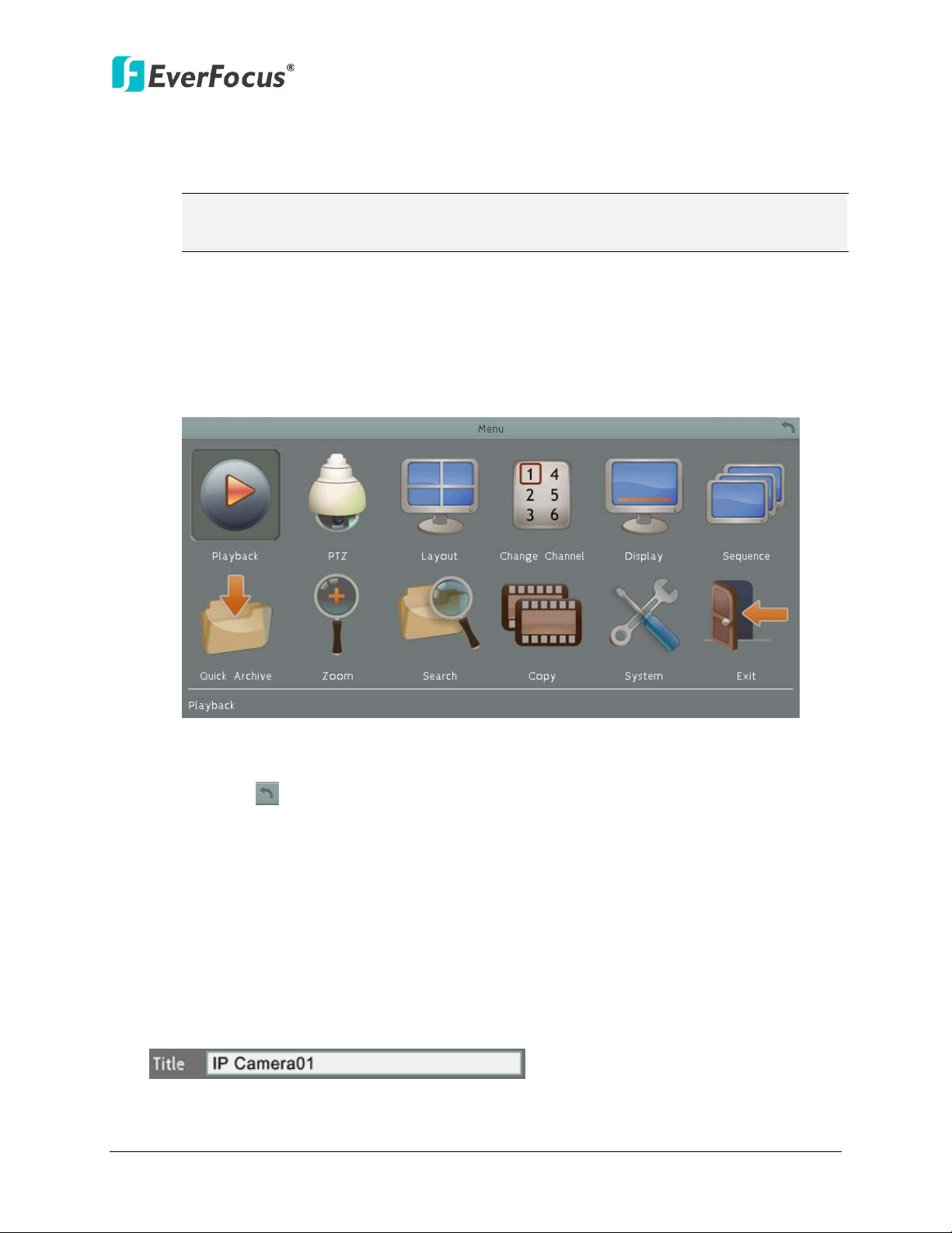
3.2 Opening OSD Root Menu
1. Right-click the mouse, the OSD Root Menu appears.
Figure 3-3
2. Click on any icon to enter the setup menus.
3. Click the
Menu.
button on the top-right corner or right-click to close the OSD Root
3.3 Field Input Option
You may found the following fields in the Configuration menu. Follow the instructions
below to configure the settings.
Text Box: Click on the box and an on-screen keyboard will appear.
30
Page 40

ENVR8304D-8CH
←
On-Screen Keyboard: Click on a button to input that character. The buttons on the right
and bottom have the following functions:
Caps Switch to capital letters
Delete the letter backwards
Confirm the selection
Move to left
Move to right
Space Enter a space
Drop-Down Box: Click on the down arrow to see all selections, then directly click on an
option to select it.
Check Box: Click on the box to enable it (checked) or disable it (unchecked).
Button: Click the button to execute the function.
Bar: Slide the bar to the left or right for adjusting the set point.
3.4 Camera Selection
You can control each camera individually by selecting that camera. To select a camera,
follow the instructions below:
1. Click a camera on the screen, and the selected camera will be highlighted with a red
frame.
2. All cameras will be selected when you scrolling the mouse up / down between the first
and the last channel.
3. Double clicking on a channel screen will display full screen for this channel.
31
Page 41

ENVR8304D-8CH
3.5 Enabling Audio
In order to utilize the audio output function, you need to enable the Record Audio function.
Please follow the instructions below before switching on the audio function.
Note: The Audio function is unavailable for Germany.
1. Connect the audio source and/or audio output amplifier to the NVR.
2. Go to Camera setting menu (OSD Root Menu > Configuration > Camera > Basic).
3. Select a camera in the Channel Number drop down list.
4. Enable the Record Audio option. You can select multiple cameras to one single audio
input device.
To turn on the audio function, please see the instructions below:
1. In the Live View window, select a channel by clicking once on the desired channel
screen.
2. On the bottom of the screen, click the Audio icon to switch the Audio Output
function to the desired camera.
3. Click the Audio icon again to disable the Audio Output function.
Note: The NVR only provide one channel audio output. You can switch the Audio Output
function to either one from the 8 cameras.
32
Page 42

ENVR8304D-8CH
1
2
3
4
5
6
7
8
9
10
11
12
No
Click to display the Layout Bar as shown below. Select a layout type for
Chapter
4
4. OSD Root Menu
Figure 4-1
Name Description
1 Playback
2 PTZ
3 Layout
Click to display the Playback Bar for viewing the recording videos. For
details, please refer to 5. Search and Playback.
Click to display the PTZ Control Panel for controlling the connected PTZ
cameras. For details, please refer to 4.1 PTZ.
the live view display on the Main Monitor. For details, please refer to 4.2
Layout Switching.
33
Page 43
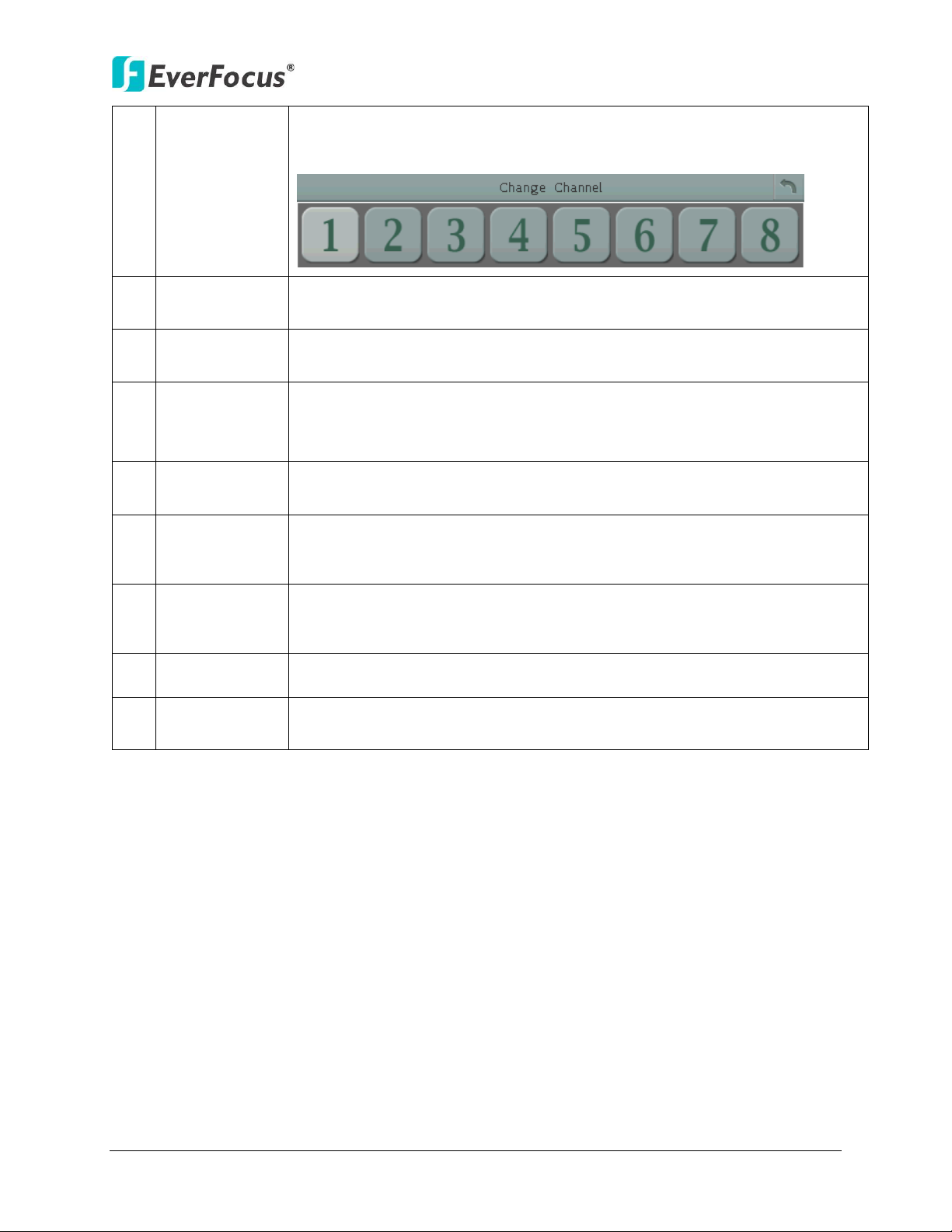
4 Channel
Click to display the Channel Changing Bar as show below. To switch the
Click to display the Search menu for setting up the Search mode for
Click to display the Copy menu for archiving the recordings or log data to
ENVR8304D-8CH
selected camera to a specific channel, please refer to 4.3 Channel
Switching.
5 Display
6 Sequence
Click to display system information icons or status icons on the live view
screen. For details, please refer to 4.4 Display.
Click to enter the auto sequential switching mode. Click again to disable.
For setting up the sequencing order, please refer to 6.5.2 M/T SEQ.
Click to quickly archive all the recordings and the EFPlayer software to
7 Quick Archive
your USB storage device. For setting up the quick archive interval, please
refer to 6.2.2 Quick Archive.
8 Zoom
9 Search
Click to enter the Zoom mode. You can zoom in the camera view up to x4
and navigate the camera view. For details, please refer to 4.6 Zoom.
playing back. For details, please refer to 5.3 Searching the Recordings for
Playback Back.
10 Copy
the USB storage device or DVD. For details, please refer to 4.7 Archiving
the Recordings or Log Data to the USB.
11 Configuration Click to enter the Configuration menu. Please refer to 6. Configuration.
12 Logout
Click to bring up the Logout Confirmation window and then click Yes to
log out the system (see 4.8 Logout). To log in, please refer to 3.1 Login.
34
Page 44

ENVR8304D-8CH
4.1 PTZ
You can use the PTZ Control Panel to control the connected PTZ cameras. To bring up the PTZ
control panel, on the OSD Root Menu, click the PTZ button .
The following actions can be performed using the PTZ Control
Panel:
1. To move the camera to the desired direction and angle,
click the Direction buttons.
2. To zoom in / out the camera view, click the Zoom buttons.
3. To adjust the camera focus, click the Focus buttons.
4. To adjust the Iris open to increase / decrease the amount of
light in, click the Iris buttons.
5. To program a Preset Position (if supported by the camera):
a. Move the PTZ camera to the desired position.
b. Click the Preset button.
c. Set up a preset number for the current position by
clicking the number buttons. The number will be
displayed in the number box.
d. Click the Set button to save the settings.
6. To jump to a Preset Position:
a. Click the Preset button.
b. Click the desired Preset number.
c. Click the Go button.
7. Shortcut for Preset 1 ~ 9:
a. Click digit 1 ~ 9 button without clicking any other
buttons.
b. The camera will seek that Preset Position.
8. To delete a Preset Position (if supported by the camera):
a. Click the Preset button.
b. Click the desired Preset number.
Figure 4-2
c. Click the Delete button.
35
Page 45

ENVR8304D-8CH
9. To operate the Auto Pan function, click the Auto Pan button.
10. To operate the Pattern function, click the Pattern button. The Pattern is the “0” Tour in
EverFocus and Pelco PTZ cameras.
11. To operate the Tour function:
a. Click the Tour button.
b. Click the desired Tour number.
c. Click the Go button.
12. To remove a pre-configured Tour (if supported by the camera):
a. Click the Tour button.
b. Click the desired Tour number.
c. Click the Delete button.
Click C to clear the entered number in the Number Box.
Click at the top-right corner to hide the PTZ Control Panel (see 4.1.1 Express Control of
PTZ). To display the PTZ Control Panel, right-click on the screen.
Click Logout to close the PTZ Control Panel and exit the PTZ mode.
Note: Before start using the Auto Pan, Pattern and Tour functions, you have to configure the
related settings for the connected PTZ cameras. Please refer to the User’s Manual of your
PTZ cameras.
36
Page 46

ENVR8304D-8CH
4.1.1 Express Control of PTZ
If the PTZ Control Panel has first been opened and then hidden, the mouse can be used to
control basic PTZ functions. Move your mouse cursor on the screen, the mouse cursor will
turn into a control icon (direction, focus or zoom) in different areas of the screen. You can
control PTZ direction, focus and zoom by clicking directly on the screen.
Figure 4-3
Direction Controls: When your mouse cursor turns into a direction icon, click on the screen
will force the camera to turn in that direction.
Focus Controls: When your mouse cursor turns into , click on the screen will focus
closer the image. When your mouse cursor turns into , click on the screen will focus
farther the image.
Zoom Controls: When your mouse cursor turns into , click on the screen will zoom in
the image. When your mouse cursor turns into , click on the screen will zoom out the
image.
37
Page 47

ENVR8304D-8CH
4.2 Layout Switching
The NVR have 4 screen division types available. The seven layouts are shown as below:
Figure 4-4
To change layout, follow the steps below:
By mouse: Right-click to bring up the OSD Root Menu and click the Layout icon. Click on the
desired layout.
By front panel: Press a desired Screen Layout button on the front panel of the NVR. To display
a channel in full-screen, press the channel buttons on the front panel.
4.3 Channel Switching
You can switch the selected camera to a specific channel. Follow the steps below:
1. On the live view screen, select a camera, the selected camera will be highlighted with a
red frame.
2. Right-click to display the OSD Root Menu.
3. Click the Channel icon , the Channel Bar appears.
Figure 4-5
4. Select a channel, the selected camera will be switched to that channel.
38
Page 48
ENVR8304D-8CH
Recording
Playback
Fast Forward
Fast Backward
Back
Pause
Alarm
Motion
Video loss
Uninstall
Audio On
Audio On
Audio Off
Alarm
Motion
Video loss
No network
No Network
Main
Call
Sequence
HDD failure
HD temp. too
Event
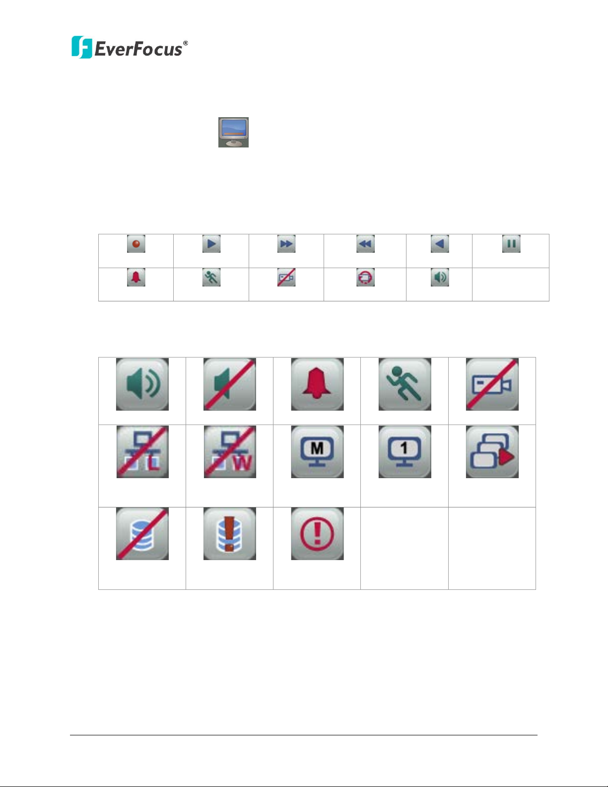
4.4 Display
You can display system and camera status on the live view screen. Follow the steps below:
1. Click the Display button on the OSD Root Menu or press the Display button on the
front panel to display the system and camera status. Click the button to choose the
desired display mode:
2. The following icons will be displayed at the top-left side of each camera stream to show
each camera’s status.
3. The following icons will be displayed at the bottom of the monitor to show the system
status.
LAN
4. There are four display modes, and you can click the Display button to change the display
mode: (1) Display both the camera and system status icons. (2) Display only the camera
status icons. (3) Display only the system status icons. (4) Hide both the camera and system
status icons.
WAN
high
39
Page 49

ENVR8304D-8CH
4.5 Sequence
The sequence function is used to display each channel in sequence mode. To enable this
function:
By Mouse: Click the Sequence button to enter the sequential switching mode. The
NVR will display one channel at a time in full screen. The channels will be displayed in the
sequence and for the amount of time as configured in the System > Display Setting > M/T SEQ
submenu. The default setting is channels 1~8 with a dwell time of 3 seconds each – repeated.
Please refer to 6.5.2 M/T SEQ for detailed information.
4.6 Zoom
You can zoom in the camera view up to 4X and navigate the camera view using the mouse.
Figure 4-6
40
Page 50

ENVR8304D-8CH
To enter the Zoom mode:
1. Select a camera and then click the Zoom button on the OSD Root Menu to zoom
in the camera view to 2X. The ZOOM 2X stamp will be displayed on the top screen.
2. Navigate the camera view to the desired position by moving your mouse cursor over the
camera view. The mouse cursor will turn into a direction icon when you move your
mouse cursor to different portion on the camera view. Click directly on the screen can
move to that direction.
Figure 4-7
3. Right-click the screen, the Zoom Bar appears in the middle of the screen.
4. Click to zoom in the camera view up to 4X.
5. Click the Logout button to log out the Zoom mode.
41
Page 51

ENVR8304D-8CH
4.7 Archiving the Recordings or Log Data to the USB
You can archive the recordings or log data (event and motion) to the USB storage device. On
the OSD Root Menu, click the Copy icon , the following menu appears.
Figure 4-8
Camera: Select the desired cameras.
Data Type: You can copy the recordings of selected cameras from main stream, sub stream or
Meta. If you want to archive the recordings with the POS transaction data, select the Meta in
the drop-down list.
Player: Check the box to include the EFPlayer program in the copy. You can use the EFPlayer
on a computer to play back the recordings.
Start Date / Time: Click to bring up the on-screen keyboard / clock to select the start date /
time.
End Date / Time: Click to bring up the on-screen keyboard / clock to select the end date /
time.
Copy To: Select whether you want to copy to USB. The log data can only be archived to the
USB storage device.
Data Size: Shows the size of the data which you want to copy.
Copy: Click to start archiving.
42
Page 52

ENVR8304D-8CH
4.8 Logout
You can log out the NVR by clicking the Logout icon on the OSD Root Menu to bring up
the Logout Confirmation window as Figure 4-9. Press “Yes” when you are ready to logout of
the system. You will need to login again before accessing the OSD Root Menu.
Figure 4-9
If you do not need the Login / Logout step before entering the Root Menu, please uncheck
the Login box in the User Management setting page. For more details, please refer to 6.8.4
User Management.
Figure 4-10
43
Page 53

ENVR8304D-8CH
5
Chapter
5. Search and Playback
You can use the Quick Playback function to play back the recordings start from the
pre-configured time or use the Search functions to search for the desired recordings for playing
back.
5.1 Quick Playback
To start using the Quick Playback function, follow the steps below:
1. To set up the start time of the playback recording, check the Quick Playback box in the
Playback setting page (OSD Root Menu > Configuration > Record & Playback > Playback)
to enable the configured time in the field below.
2. Enter the desired time for playing back the recording. Take 60 seconds for example, if the
current system clock time is 17:35:00, the start time for the playback recording will start
from 17:34:00 (60 seconds ago from 17:35:00).
Figure 5-1
3. On the Live View Window, select a desired camera or select all channels, right-click to
bring up the OSD Root Menu, and then click the Playback button .
4. The recording has been playing back and the Playback Bar appears on the bottom of the
screen.
44
Page 54

ENVR8304D-8CH
2
6
8
9
1
7
11
12
2013/01/01 00:00:00 2013/01/01 00:15:00 2013/01/01 00:30:00
3
4
5
10
13
14
15
16
17
5.2 Playback Bar
The playback bar is the fastest way to show video from the exact time which users want to see.
The playback bar allows users to see both a timeline and the current playback indicator. Users
can then click the timeline to move the indicator to the desired position.
Figure 5-2
No. Name Description
1 Date/Time Click to set up the start time of playback recording.
Move the slider to the left / right on the Time Bar to select the
2 Time Bar
3 Playback Speed Indicates the current Playback Speed.
4 Express Copy
5 Close
6 Main /Sub Stream Click to select the recorded data from main or sub stream
7 Fast Reverse Click to play the recorded data in fast reverse.
8 Reverse Play/Pause
9 Stop
time for playing back. The status of each camera is presented by
different colors on the Time Bar. GreenNormal,
OrangeMotion, BlueVideo Loss, RedAlarm Event.
Click to bring up the Copy menu for archiving the recordings /
log data to the USB storage device or DVD burner. For details,
please refer to 4.7 Archiving the Recordings or Log Data to the
USB.
Click to hide the Playback Bar. To bring up the Playback Bar
again, move your cursor to the lower side of the screen.
Click to play the recorded data in reverse at normal speed. Click
this button again to Pause the reverse playback. Click the Stop
button to stop all playback actions and exit the playback area.
Click to stop either the Reverse, Fast Reverse, Play, and Fast
Forward functions, if that function is active. This button stops all
Play functions, but no Recording functions.
45
Page 55

ENVR8304D-8CH
L1: Entire Time Bar scale is 30 days.
Use the + and - buttons to adjust the time scale range for the
the level, the Start Time and End Time will change.
No. Name Description
Click to play the recorded data forward. Click this button again
10 Play/Pause
to Pause the playback. Click the Stop button to stop all playback
actions and exit the playback area.
11 Fast Forward Click to play the recorded data in fast forward.
L2: Entire Time Bar scale is 2 weeks.
12 Time Scale
L3: Entire Time Bar scale is 1 week.
L4: Entire Time Bar scale is 1 day.
L5: Entire Time Bar scale is 1 hour.
L6: entire Time Bar scale is 30 minutes.
13
Time Bar Scale
bar. The scale range includes 6 options (levels). When changing
14
15 Start Time Indicates the playback start time.
16 Current Playback Time Indicates the current playback time.
17 End time Indicates the playback end time.
46
Page 56

ENVR8304D-8CH
5.3 Searching the Recordings for Playing Back
You can search the recordings for playing back by using the Search menu. On the left side of
the Search menu, select Time Search, Event Search, Smart Search, Snapshot Search or POS
search to enter to the setup menu.
To bring up the Search menu:
By Mouse: Right-click to bring up the OSD Root Menu, and then click the Search button .
By Front Panel: Press the Search button.
Figure 5-3
5.3.1 Time Search
Figure 5-4
Start Date: Click to bring up the on-screen keyboard to select the date.
Start Time: Click to bring up the on-screen clock to select the time.
Play: Click to start playing back.
47
Page 57

ENVR8304D-8CH
5.3.2 Event Search
Figure 5-5
Start Date / End Date: Click to bring up the on-screen keyboard to select the start / end
date.
Start Time / End Time: Click to bring up the on-screen clock to select the start / end time.
Camera: Select the desired cameras to be searched.
Event: Select an event type to be searched.
Search: Click to start searching. The search results will be listed in the Event List menu as
shown below.
Figure 5-6
Previous / Next: Click to go to the previous / next page.
Play: Click to playback the selected items.
48
Page 58
ENVR8304D-8CH
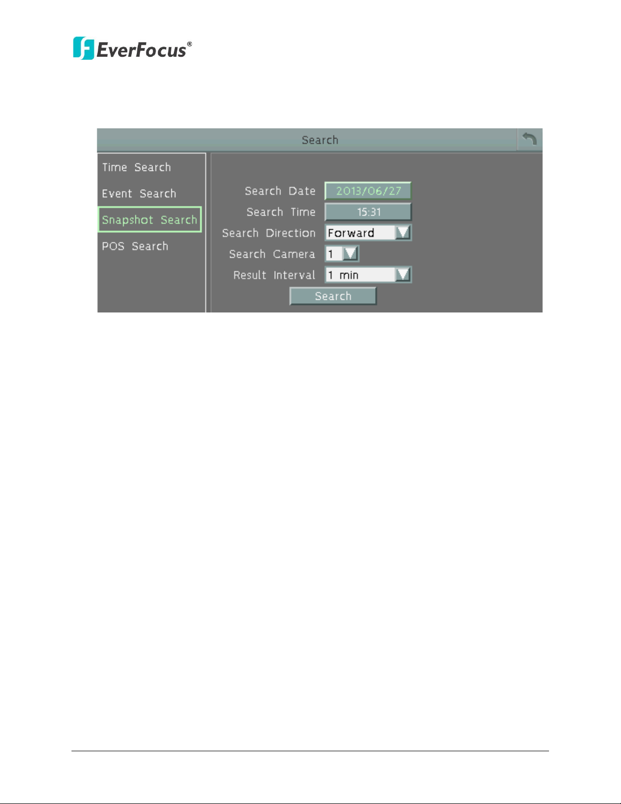
5.3.3 Snapshot Search
You can display video frames in snapshot and resume a video from where the snapshot
has been set up.
Figure 5-9
Search Date: Click to bring up the on-screen keyboard to select the date.
Search Time: Click to bring up the on-screen clock to select time.
Search Direction: Click to search forward / backward based on the setup time above.
Search Camera: Select a desired camera to be searched.
Result Interval: Click to set up the interval for the snapshots of the video frame. For
example, if you select 5 minutes, the video frame will be snapshotted with 5-minute
interval (see image below).
Search: Click to start searching. The search results will be displayed in 16 screen division
(see image below).
49
Page 59
ENVR8304D-8CH
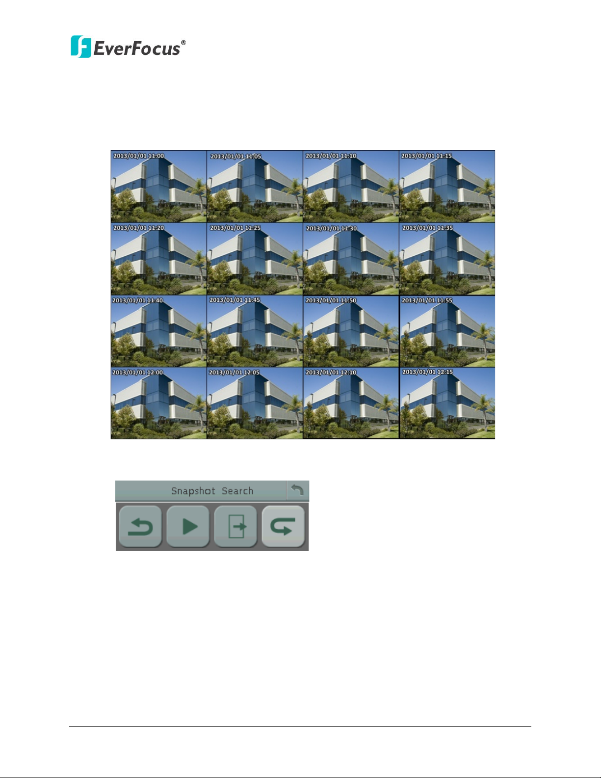
Previous
Play Close
Next
To resume the video:
1. Click the Search button, the search results are displayed in 16 screen division. In this
picture, you can see the time layouts on the upper-left corner of each snapshot, which
are set up with 5-minute interval.
Figure 5-10
2. Right-click on the screen, the Resume Playback Bar appears in the middle of the screen.
Figure 5-11
3. Click the Previous or Next buttons to display the previous / next snapshots.
4. Select a snapshot by clicking on the snapshot, the selected snapshot will be highlighted
with a white frame.
5. Click the Play button to resume the video.
6. Click the Close button to close the Resume Playback Bar and then return to the
Snapshot Search menu.
50
Page 60

ENVR8304D-8CH
5.3.4 POS Search
The POS Search function allows users to search and play back the recordings with the POS
transaction data within a specific time.
Figure 5-12
Start Date / End Date: Click to bring up the on-screen keyboard to select the start / end
date.
Start Time / End Time: Click to bring up the on-screen clock to select the start / end time.
POS String: Click to bring up the on-screen keyboard. Type any desired keyword to search
the specific transaction data.
Search: Click to start searching. The search results will be listed in the Event List menu as
shown below.
Figure 5-13
Previous / Next: Click to go to the previous / next page.
Play: Click to playback the selected items.
51
Page 61

ENVR8304D-8CH
You need to set up the POS settings before searching the video with POS transaction data.
Please follow the steps below:
1. Connect the POS system to the RS-232 port at the rear panel of the NVR.
2. Make sure the RS-232 settings of the NVR are the same as those of the POS system.
Select the Text Insert in the Type drop-down list. (OSD Root Menu > Configuration >
System Setting > I/O control).
Figure 5-14
3. Check the Text Insert box in the Monitor OSD setting page to display the transaction
data on the screen (OSD Root Menu > Configuration > Display > Monitor OSD).
Figure 5-15
4. The transaction data, such as date, time, item, price and any customized information,
synchronized with the surveillance video will be displayed on the screen, shown as
the image below.
Figure 5-16
52
Page 62
ENVR8304D-8CH
6
Chapter
6. Configuration
The ENVR8304D-8CH can be configured through a series of menus on screen by using a Mouse,
the supplied IR Remote Control, or the optional device EKB500 keyboard. The following
operations are examples of using a Mouse. This chapter describes the functions and options of
the Configuration Setting in the on-screen display (OSD) menus. Right-click the mouse, the OSD
Root Menu appears. Click the Configuration button , the following Configuration Menu
displayed with 9 setup options appears.
Figure 6-1
53
Page 63

ENVR8304D-8CH
6.1.1 Camera Status
6.2.1 Record
6.3.1 Alarm
6.4.1 Disk
6.5.1 Monitor OSD
6.6.1 LAN & WAN
6.7.1 Express Setup
6.8.1 Date / Time
6.9.1 Configuration
6.9.2 Log
List of Configuration Options:
Please find the topic of interest by referring to the section prefixed to each option.
6.1.2 Basic
6.1 Camera
6.1.3 PTZ
6.1.4 Tracking
6.1.5 Pattern Tour
6.1.6 Adjust
6.2 Record & Playback
6.3 Event
6.4 Disk
6.5 Display Setting
6.6 Network
6.7 Schedule
6.2.2 Quick Archive
6.2.3 Playback
6.3.2 Connection Loss
6.3.3 Motion
6.3.4 Other
6.4.2 Lock/Format
6.4.3 RAID
6.5.2 M/T SEQ
6.6.2 Email
6.6.3 DDNS
6.6.4 FTP
6.6.5 Alarm Server
6.6.6 Network Test
6.7.2 Holidays
6.7.3 Schedule
6.8 System Setting
6.9 System Information
6.8.2 Daylight Saving Time
6.8.3 User Group
6.8.4 User Management
6.8.5 I/O Control
6.8.6 EKB200
6.8.7 Miscellaneous
54
Page 64

ENVR8304D-8CH
6.1 Camera
If the NVR doesn’t detect any IP cameras, the Basic, PTZ, Tracking, Pattern Tour and Adjust
setting pages cannot be used. Therefore, make sure the IP cameras are properly connected to
the NVR via the Smart Switch.
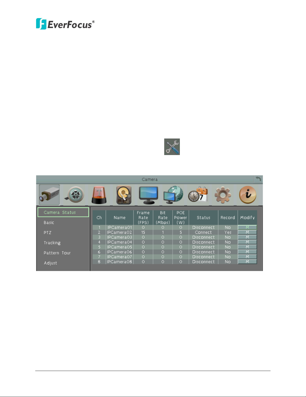
6.1.1 Camera Status
This page displays connected IP cameras’ status and also allows users to modify the ID and
Password of the IP cameras.
Figure 6-2
Channel: Displays the channel number.
Name: Shows the name of the connected IP camera.
Frame Rate: Shows the current frame rate of the connected IP camera.
Bit Rate: Shows the current Bit Rate of the connected IP camera.
PoE Power: Shows the current Bit Rate of the connected IP camera.
Status: Shows the connection status.
Record: Shows the recording status.
Modify: Click to bring up the following window and you can modify the ID and Password of
the connected IP camera.
Figure 6-3
55
Page 65

6.1.2 Basic
ENVR8304D-8CH
Figure 6-4
Channel Number: Select a desired channel for configuration.
Device Title: Enter a camera title.
Record Dual Stream: Select to enable or disable the dual streams recording function.
Record Mode: Select a recording mode from the drop-down list.
Normal+Event: Set all cameras to the Continuous and Event recording mode.
Event Only: Set all cameras to the Event only recording mode.
Record Audio: Check the box to enable audio recording on the NVR. Note that the Audio
function is unavailable for Germany.
【Main / Sub Stream】You can separately configure the settings for the Main and Sub
Streams.
Resolution: Select a desired recording resolution.
Record Quality: Select a image quality of the camera.
Normal Speed: Select a frame rate per second (FPS) for continuous recording. The frame
rate is limited by the maximum total recording capacity of the NVR as allocated across all
the installed cameras.
56
Page 66

ENVR8304D-8CH
Event Speed: Select a frame rate per second (FPS) for continuous recording. The frame rate
is limited by the maximum total recording capacity of the NVR as allocated across all the
installed cameras.
Apply To: Click to apply the same settings to the desired cameras.
Save: Click to add the camera and save the current settings.
57
Page 67

ENVR8304D-8CH
Click the direction buttons to force the
camera to turn into that direction
Click to stop thet current action, such
as Auto Pan, Tour or Pattern
Click to Zoom In
/Out
Click to widen/narrow down the IRIS
opening
Click to Focus Near/Far
6.1.3 PTZ
You can set up the Preset and Auto Pan settings in this page.
Figure 6-4
【Camera】: Select a PTZ camera.
【Speed】: Select a pan and tilt speed from the Speed drop-down list for the camera to move
to the directions when you use the direction buttons during the configuration period
【PTZ Control Pad】:
Figure 6-5
58
Page 68

ENVR8304D-8CH
Preset: You can configure up to 192 preset positions in this field.
Figure 6-6
To set up a Preset Positions:
1. Adjust the camera view to a desired position using the direction button. You can select the
pan / tilt speed from the Speed drop-down list for controlling the direction buttons. Adjust
zoom, focus and Iris if necessary.
2. To set up the current camera view as a preset position, select a preset number from the
Preset No drop-down list for the current camera view.
3. Optionally set up a title for this preset position in the Title field .Click Apply to save the title
name or click Reset to reset the current changes.
4. Click Set to save the current position as the Preset Number you have selected.
5. Follow Step 1 to 4 to set up another preset position. You can click the Next button to go to
the next page and then click the Preset No drop-down list to select a number. Or click on
the number in the Page field to select a preset number.
To activate the Preset function on the PTZ Live View window, click the PTZ icon on the
OSD Root Menu. Click the Preset button, click on the numeric buttons to select a Preset
number and then click the Go button. The selected Preset position should be displayed on the
camera view. Please refer to 4.1 PTZ for detailed instructions.
59
Page 69

ENVR8304D-8CH
Auto Pan: You can only configure one Auto Pan sequence. The configured Auto Pan (A to B Pan)
sequence will always be numbered as “1”. The number “2” will always be an endless pan
around the given (not preconfigured) X/Y tilt axis.
Figure 6-7
Endless Mode: The Endless Mode is always numbered as “99” in the PRESET function. If you
select On, the Preset number “99” will be the 360° endless pan function; if you select Off, the
Preset number “99” will be the preconfigured A to B Pan function. To use the function, go to
PTZ live view page first. Click the Preset button and click the Preset number “99”. Finally, click
Go to activate the Endless Mode.
To set up an Auto Pan Sequence:
Using the direction buttons to adjust the camera view to a desired position where you want
1.
to set up the position as the Left Position. You can select the pan / tilt speed from the
Speed drop-down list for controlling the direction buttons. Adjust zoom, focus and Iris if
necessary.
2. Click the Set L Position button to save the current position as the Left Position.
3. Follow Step 1 to set up the Right Position and then click the Set R Position to save the
current position as the Right Position.
4. Enter a dwell time (1~99 seconds) for the Left and Right positions (the time that the
camera will pause at each position).
5. Enter a speed (1~255) at which the camera will move during the Auto Pan sequence.
6. Click Save to save the settings.
To activate the configured Auto Pan on the PTZ Live View window, click the PTZ icon on
the Menu Bar. Click the Auto Pan button, click “1” on the numeric buttons and then click the
Go button. The camera will continuously move to the left and right positions which you have
configured. Click “2” on the numeric buttons and then click the Go button will force the camera
to pan 360° endlessly. To stop the Auto Pan function, click the Stop button on the PTZ
Control panel.
60
Page 70

6.1.4 Tracking
Note: If the user did not set up a start point or the start point is disabled, the camera will
ENVR8304D-8CH
Figure 6-8
To set up the Auto Tracking function:
1. Auto Tracking Start Point: Check the box to enable a camera position to which the camera
will return to after a tracking operation. Use the direction buttons to adjust the camera
view to a desired position where you want to set up the position as the Auto Tracking Start
Point. You can select the pan / tilt speed from the Speed drop-down list for controlling the
direction buttons. Adjust zoom, focus and Iris if necessary. Click Set to set the position as
the Auto Tracking Start Point.
go back to track/monitor the initial point instead of the Auto Tracking Start Point, once
the tracked object exits in the camera’s field of view.
2. Pan/Tilt Limit: Check the box if you want to create a zone where the camera will track the
movement inside the zone only. Before clicking the Upper/Lower/Right/Left buttons, use
the direction buttons to adjust the camera view to a desired position where you want the
camera to track the movement in that zone. You can select the pan / tilt speed from the
Speed drop-down list for controlling the direction buttons. Adjust zoom, focus and Iris if
necessary. Click the Upper/Lower/Right/Left buttons to set up the Pan/Tilt limits (Left and
Right for the Pan limit; Upper and Lower for the Tilt limit).
61
Page 71

ENVR8304D-8CH
Note: Please note that if enabling the Pan/Tilt Limits function, the position of the Start
Note: In the on-going auto tracking process after object is identified, the PTZ function
tracking may incorrectly assume the object is lost and ends the tracking process.
Point should be within the range of the Pan/Tilt Limits, or there will be a pop-up message
showing “Setting error: Start Point is not inside Pan/Tilt Limits”.
Zoom control on tracking:
Keep current zoom ratio: the current zoom ratio will stay fixed during the tracking
process.
Multi-step zoom function: the zoom ratio will change according to the distance of the
object against the camera. When the object is moving further away, the camera will
keep zooming in to track; on the other hand, when moving closer, the camera will zoom
out to check whether it should track the object or not.
Tracking Duration: User can set the tracking time duration of the camera (0~600
seconds). When the Tracking Duration is up, the camera will return to the Start Point.
The function is used to prevent the camera from tracking an object which is intentionally
set to lure the camera away.
When the object is lost on the screen: User can select a tracking mode when the object
is lost on the screen. The options are:
Keep tracking: The camera will stop at the current position and wait for another moving
object in the camera's field of view. Then, the camera will track the new object without
changing zoom ratio.
Zoom out and look for a new object: The camera will zoom out at the current position
immediately for expanded the field of view and restart tracking a new moving object
appearing in the camera's field of view.
Stop tracking and zoom out: The camera will stop auto tracking and stay at the current
position. Then, the camera will zoom out for expanded the field of view.
In sec and Back to Start Point: Set up a period of time for the camera to stay at the
current position before returning to the Start Point (0 is returning to Start Point without
any waiting).
Resume from manual stop: The function is used to set up the Auto Tracking restart time
(0~600 seconds). If user manually operates the PTZ function during auto tracking
process, the auto tracking function will stop. When the manual operation ceases, the
camera will resume to “Auto Tracking Start Point” after a given period of time. Setting of
value 0 indicates do not restart.
keeps the moving object in the center of the screen. But the PTZ function may stop if the
object moves too slow and stays in center of the screen too long. In case like this the auto
62
Page 72

ENVR8304D-8CH
6.1.5 Pattern Tour
Figure 6-9
Pattern: You are given 90 seconds to move the camera (via the PTZ buttons) to different
positions (and different zoom / focus / Iris positions). The camera then saves that sequence
under the Pattern No. you’ve selected. Up to 4 Patterns can be configured.
To set up a Pattern Sequence:
1. Select a pan and tilt speed from the Speed drop-down list for the camera to move to the
directions when you use the direction buttons during the configuration period.
2. Select a pattern number from the Pattern No drop-down list.
3. Click the Set button to start the 90-second configuration period. Use the direction / zoom /
focus / Iris buttons to move the camera in the desired sequence.
4. Click the Complete button again to end the configuration.
Click Clear can void the configuration for the entered Pattern No. Click Go to view/test the
configured Pattern sequence.
To activate the Pattern function on the PTZ Live View window, click the PTZ icon on the
Menu Bar. Click the Pattern button, click on the numeric buttons to select a Pattern number
and then click the Go button. The camera will move to the positions in the Pattern sequence
you have configured. To stop the Pattern function, click the Stop button on the PTZ
Control panel. Please refer to 4.1 PTZ for detailed instructions.
63
Page 73
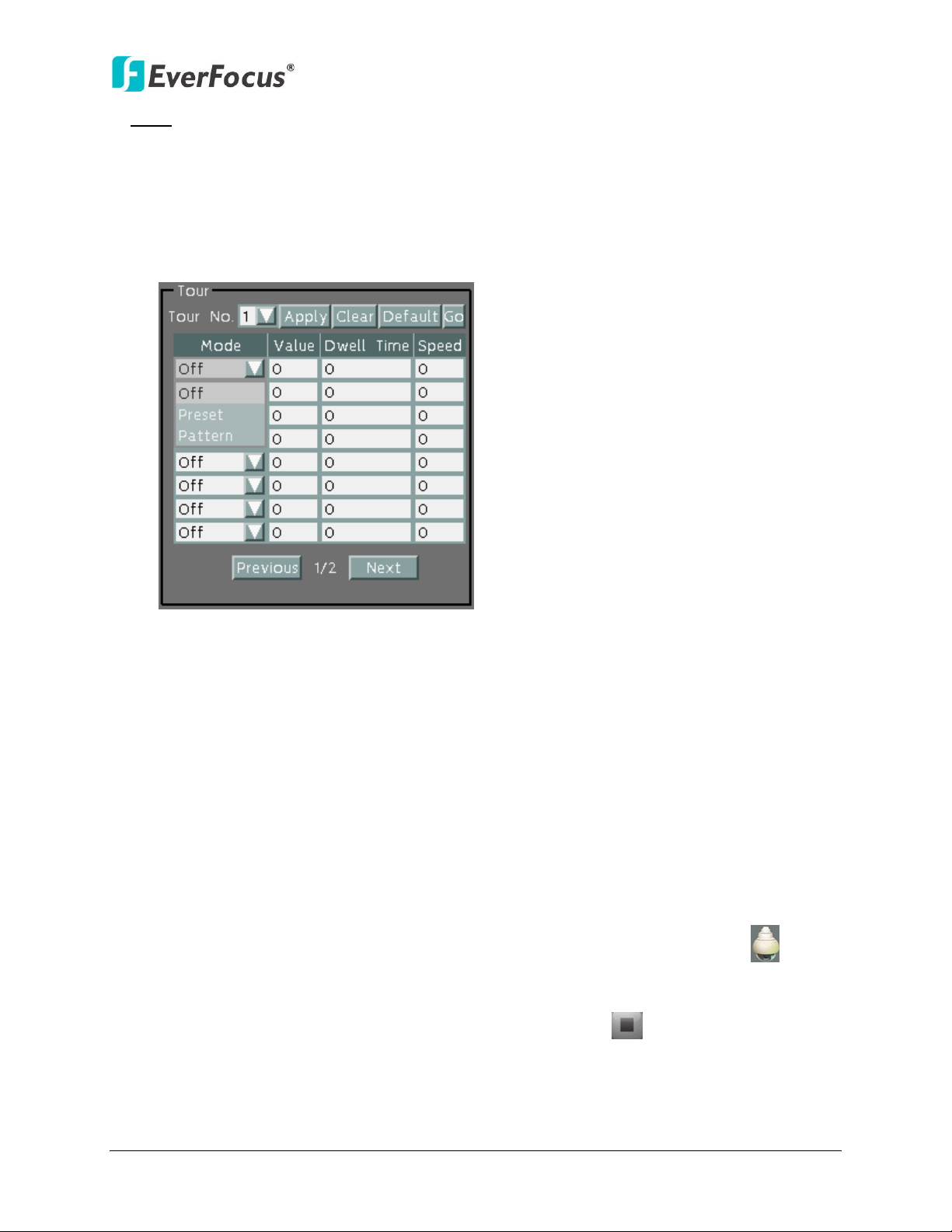
ENVR8304D-8CH
Tour: You can combine up to 16 preconfigured camera positions and patterns into one long
sequence. Up to 16 Tour sequences can be set up.
To set up a Pattern Sequence:
1. Select a number from the Tour No drop-down list.
2. To set up the first position for Tour No.1, select OFF, Preset or Pattern in the Mode field.
Figure 6-10
3. Enter a Preset No. or Pattern No. in the Value field.
4. Enter a dwell time (1~99 seconds) in the Dwell Tour field that the Tour will pause at a
Preset position or after a Pattern sequence.
5. Enter a speed (1~255) at which the camera will move to the Preset position or first point of
the Pattern sequence.
6. Follow Step 3 to 5 to configure up to 16 positions for Tour No.1.
7. To configure another Tour sequences, select a number from the Tour No drop-down list
and follow Step 3 to 6 to configure up to 16 positions for the selected Tour number.
8. Click Apply to apply the settings. Click Clear to clear the current settings for the selected
Tour No.; click Default to set the Tour Sequence to Default setting; click Go to view/test
the configured Tour sequence.
To activate the Tour function on the PTZ Live View window, click the PTZ icon on the
Menu Bar. Click the Tour button, click on the numeric buttons to select a Tour number and
then click the Go button. The camera will move to the positions in a long sequence you have
configured. To stop the Pattern function, click the Stop button on the PTZ Control panel.
Please refer to 4.1 PTZ for detailed instructions.
64
Page 74
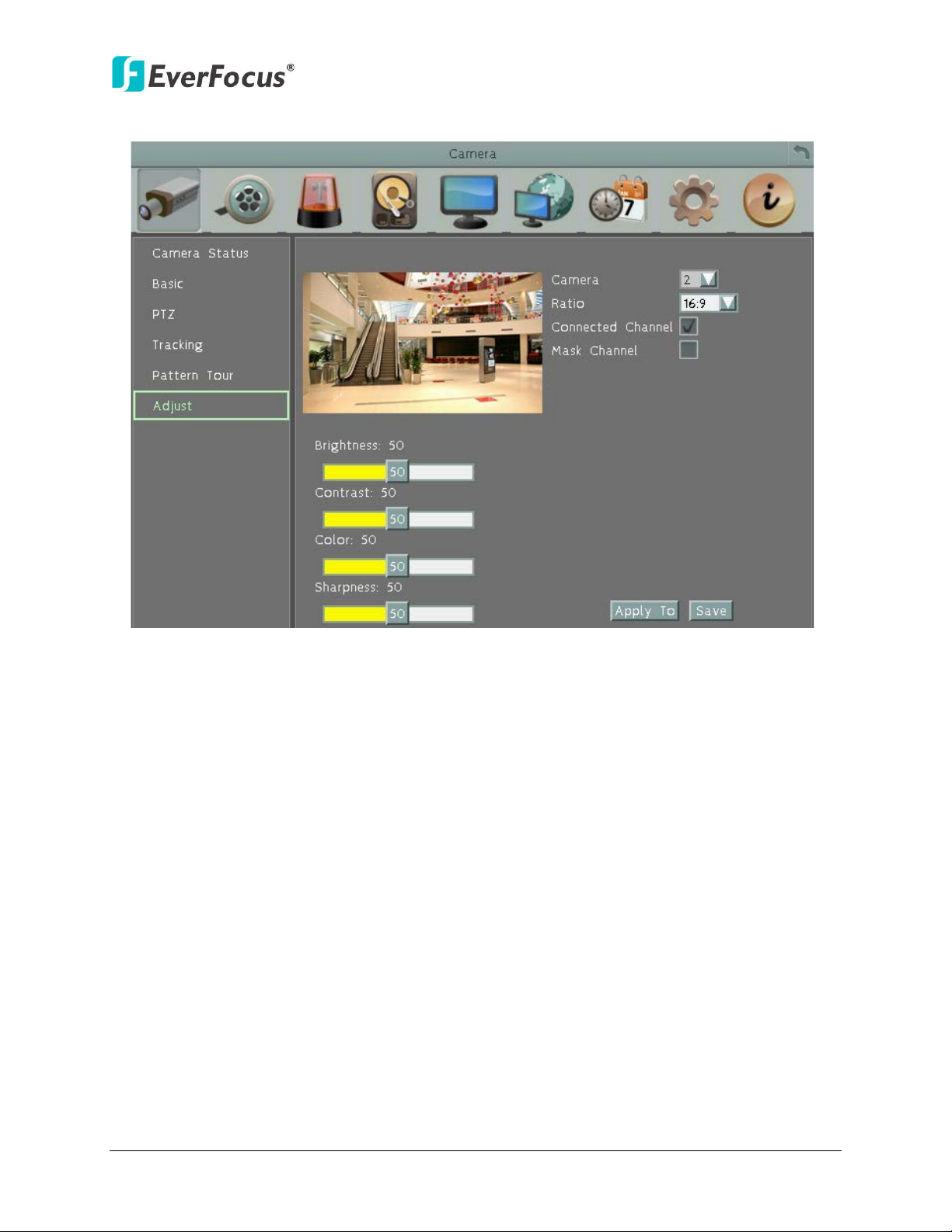
6.1.6 Adjust
ENVR8304D-8CH
Figure 6-11
Camera: Select a desired camera for adjusting the following settings.
Ratio: Select 4:3 or 16:9 display aspect ratio of a camera, and its video will be displayed in 4:3
or 16:9 format on that channel screen. Please refer to 2.3.4 Display Aspect Ratio for more
details.
Connected Channel: Check the box to enable the connection between the camera and the
NVR. If the box is unchecked, the system will disconnect the camera and stop recording.
Mask Channel: Check the box to mask the camera’s live view on the screen, but the
recording function is still on.
Brightness: Move the bar to adjust the brightness.
Contrast: Move the bar to adjust the contrast.
Color: Move the bar to adjust the color.
Sharpness: Move the bar to adjust the sharpness.
Apply To: Click the button to apply the same settings to the desired cameras.
Save: Click to save the settings.
65
Page 75
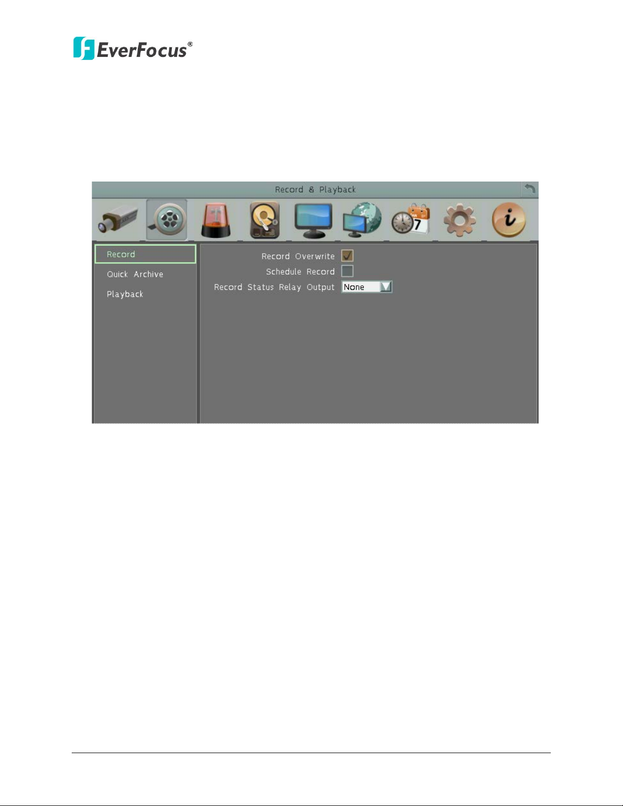
ENVR8304D-8CH
6.2 Record & Playback
You can configure the basic recording settings on the hard disk. You can also configure the
settings for Quick Archive and Quick Playback.
6.2.1 Record
Figure 6-12
Record Overwrite: Check the box to overwrite the hard disk when it is full. Note that unless
this box is checked, or the NVR will stop recording when the hard disk is full. The use of
record overwrite is strongly recommended. If you do not use this feature, please be sure to
enable the Event setting for Disk Full for notification (see 6.3.4 Other).
Schedule Record: Check the box to record by the schedule. Please see 6.7 Schedule for
more details.
66
Page 76

ENVR8304D-8CH
6.2.2 Quick Archive
Figure 6-13
You can quickly archive all the recordings to the USB storage device
1. Plug an USB storage device before quick archiving.
2. Click the Quick Archive Interval drop-down list and select an interval time (1, 5, 10, 15, 20,
30 or 60 minutes). For example, if you set up 60 minutes for the Archive Interval, the NVR
will archive the recordings 60 minutes ago from the current time to the storage device.
3. Click the Save button to save the setting.
4. Go to the OSD Root Menu, click the Quick Archive button and then the Quick
Archive process begins. The EFPlayer software will also be copied to the storage device
automatically.
Note: If the space of the storage is insufficient, the copies will end at the time when the
storage space is full.
67
Page 77
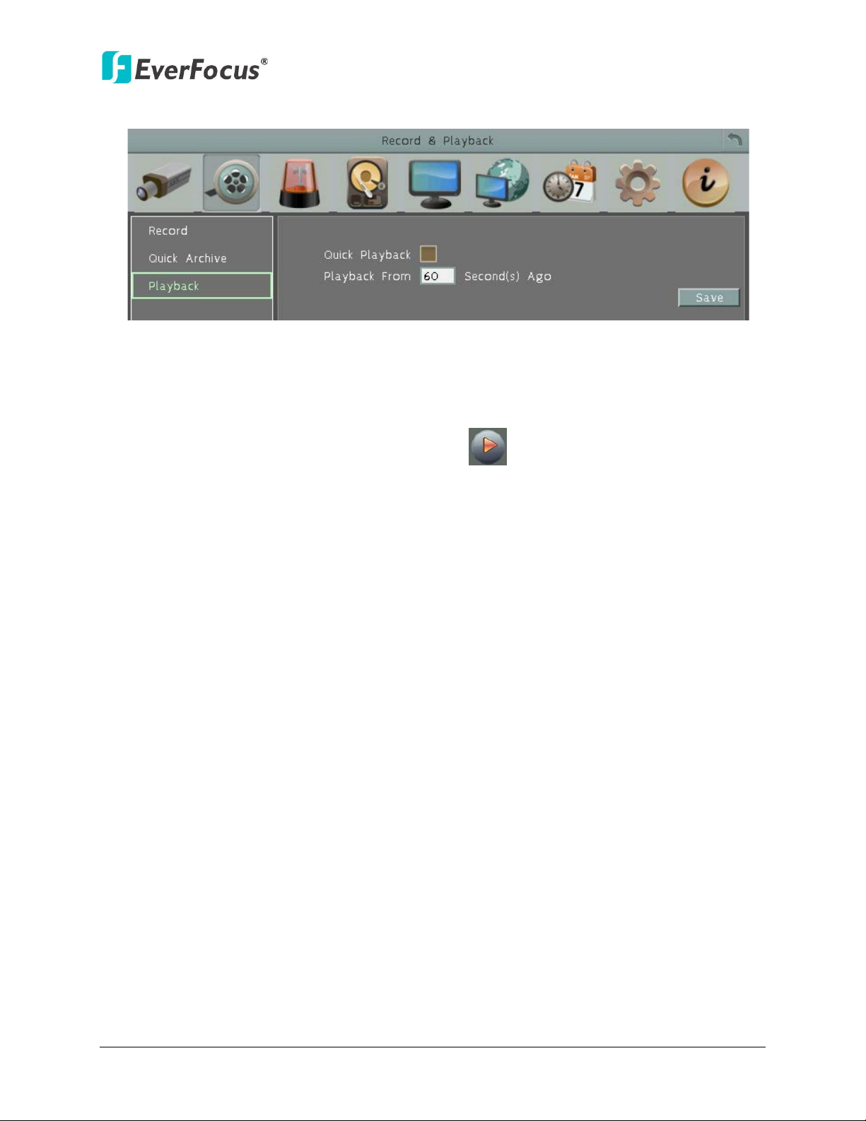
ENVR8304D-8CH
6.2.3 Playback
Figure 6-14
Quick Playback: Check the box to enable the configured playback start time in the below
field.
Playback from X seconds ago: Set up a time between 60 and 3600 seconds for the playback
start time. When you click the Playback button on the DSD Root menu, the system
will play back the recordings start from the setup time.
68
Page 78
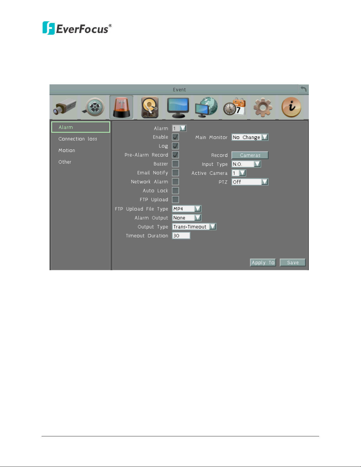
ENVR8304D-8CH
6.3 Event
You can configure the Alarm, Connection Loss, Motion and Other settings in this menu.
6.3.1 Alarm
Figure 6-15
Alarm: Select an Alarm input number from 1 to 2.
Enable: Check the box to enable the Alarm trigger function for the selected alarm input.
Log: Check the box to record alarm events to log data.
Pre-alarm Record: Check the box to start copying the recordings to the hard disk from 5
seconds before the alarm event occurs. Note that the pre-alarm recording rate will follow the
Normal Speed configured in the earlier section (see 6.1.2 Basic).
Buzzer: Check the box to enable the buzzer when an alarm event is triggered.
Email Notify: Check the box to send email notification when an alarm event is detected.
Email operation requires valid email entered in the Email setup menu (see 6.6.2 Email).
Network Alarm: Check the box to send out a network alarm to a client PC when an alarm
event occurs. This feature works with EverFocus’ CMS software. You will need to configure
the Alarm Server for the NVR to send network alarms to the client PC (see 6.6.5 Alarm
Server).
69
Page 79

ENVR8304D-8CH
Auto Lock: Check the box and the events will be recorded in a write protected segment of
the hard disk (will not be overwritten). The NVR will lock a period of time when the alarm
occurs. The length of the time depends on NVR setting (see 6.4.2 Lock / Format).
FTP Upload: Check the box to enable uploading recordings to the FTP server function. To
setup the FTP server, please refer to 6.6.4 FTP.
FTP Upload File Type: Select MP4 file type to upload videos to FTP server; select JPEG file
type to upload snapshots to the FTP server.
Alarm Output: Select an alarm output number. When an alarm is triggered, the signal will be
transmitted through the selected alarm output relay.
Output Type: Select an output type when an alarm is triggered.
Timeout: Select this option and then set up the Timeout Duration in the field below, the
alarm output will last for the setup duration time (10 ~ 150 seconds).
Permanent: Alarm will remain active until the user presses the “Enter” key on the IR
Remote Control or resets the alarm remotely.
Transparent: Alarm output remains as long as the alarm input is active.
Trans + Timeout: Alarm output continues until event ends, then continues for the setup
duration time (10 ~ 150 seconds).
Timeout Duration: This function only appears when you select Timeout or Trans + Timeout
options in the Output Type drop-down list. Select a duration time for the motion event. The
alarm output will last for the setup duration time between 1 and 150 seconds.
Main Monitor: Select Full Screen to force the camera associated with the selected alarm
number to display full screen on the Main Monitor. The full screen camera view will last
according to the Output Type selected in the field above.
Record: Select a camera to start recording when the associated alarm number is triggered.
Input Type: Select an input type when the selected alarm number is triggered. The options
include N.O. and N.C.
Active Camera: This function is for associating an alarm trigger with a specific camera. For
example, if you set up an external motion detector near Camera 2, you can select Camera 2
in this field. The alarm will be associated with this camera for full screen display, event
logging and PTZ actions.
PTZ: If the Active Camera selected above is a PTZ camera, you can further set up the PTZ
actions in this field.
Apply To: Click the button to apply the same settings to the desired cameras.
70
Page 80

ENVR8304D-8CH
6.3.2 Connection Loss
Figure 6-16
Camera: Select a camera to be configured.
Enable: Check the box to enable the Video Loss event settings for the selected camera.
Log: Check the box to record video loss events to log data.
Buzzer: Check the box to enable the buzzer when a video loss event is triggered.
Email Notify: Check the box to send email notification when a video loss event is detected.
Email operation requires valid email entered in the Email setup menu (see 6.6.2 Email).
Network Alarm: Check the box to send out a network alarm to a client PC when video loss
event occurs. This feature works with EverFocus’ CMS software. You will need to configure
the Alarm Server for the NVR to send network alarms to the client PC (see 6.6.5 Alarm
Server).
Alarm Output: Select an alarm output number. When an alarm is triggered, the signal will be
transmitted through the alarm output relay.
71
Page 81

ENVR8304D-8CH
Output Type: Select an output type when an alarm is triggered.
Timeout: Select this option and then set up the Timeout Duration in the field below, the
alarm output will last for the setup duration time (10 ~ 150 seconds).
Permanent: Alarm will remain active until the user presses the “Enter” key on the IR
Remote Control or resets the alarm remotely.
Transparent: Alarm output remains as long as the alarm input is active.
Trans + Timeout: Alarm output continues until event ends, then continues for the setup
duration time (10 ~ 150 seconds).
Timeout Duration: This function only appears when you select Timeout or Trans + Timeout
options in the Output Type drop-down list. Select a duration time for the motion event. The
alarm output will last for the setup duration time between 10 and 150 seconds.
Apply To: Click the button to apply the same settings to the desired cameras.
72
Page 82

6.3.3 Motion
ENVR8304D-8CH
Figure 6-17
Camera: Select a camera to be configured.
Enable: Check the box to enable the Motion Event settings for the selected camera.
Log: Check the box to record motion events to log data.
Pre-alarm Record: Check the box to start copying the recordings to the hard disk from 5
seconds before the motion event occurs. Note that the pre-alarm recording rate will follow
the Normal Speed configured in the above section (see 6.1.2 Basic).
Buzzer: Check the box to enable the buzzer when a motion event is triggered.
Email Notify: Check the box to send email notification when a motion event is detected.
Email operation requires valid email entered in the Email setup menu (see 6.6.2 Email).
Network Alarm: Check the box to send out a network alarm to a client PC when motion
occurs. This feature works with EverFocus’ CMS software. You will need to configure the
Alarm Server for the NVR to send network alarms to the client PC (see 6.6.5 Alarm Server).
Auto Lock: Check the box and the events will be recorded in a write protected segment of
the hard disk (will not be overwritten). The NVR will lock a period of time when the alarm
occurs. The length of the time depends on NVR setting (see 6.4.2 Lock / Format).
73
Page 83

ENVR8304D-8CH
FTP Upload: Check the box to enable uploading recordings to the FTP server function. To
setup the FTP server, please refer to 6.6.4 FTP.
FTP Upload File Type: Select MP4 file type to upload videos to FTP server; select JPEG file
type to upload snapshots to the FTP server.
Alarm Output: Select an alarm output relay. When an alarm is triggered, the signal will be
transmitted through the selected alarm output relay.
Output Type: Select an output type when an alarm is triggered.
Timeout: Select this option and then set up the Timeout Duration in the field below, the
alarm output will last for the setup duration time (10 ~ 150 seconds).
Permanent: Alarm will remain active until the user presses the “Enter” key on the IR
Remote Control or resets the alarm remotely.
Transparent: Alarm output remains as long as the alarm input is active.
Trans + Timeout: Alarm output continues until event ends, then continues for the setup
duration time (10 ~ 150 seconds).
Timeout Duration: This function only appears when you select Timeout or Trans + Timeout
options in the Output Type drop-down list. Select a duration time for the motion event. The
alarm output will last for the setup duration time between 10 and 150 seconds.
Main Monitor: Select Full Screen to force the camera which detects motion to display full
screen on the Main Monitor. The full screen camera view will last according to the Output
Type selected in the field above.
Edit Motion Grid: Press the button to bring up the Motion Setting menu. To edit the motion
grids, please refer to the instructions later in this section.
Apply To: Click the button to apply the same settings to the desired cameras.
74
Page 84

ENVR8304D-8CH
To Edit the Motion Grids:
1. Click the Edit Motion Grid button, the Motion Setting menu appears.
Figure 6-18
2. Click on the image and the grid will be displayed.
3. To set up a motion area, drag a rectangle with your mouse (from top to bottom / upper- left
to lower-right). The selected areas will be highlighted in green (see image below).
4. To delete a motion area, drag a rectangle with your mouse (from bottom to top / lower-right
to upper-left).
5. Follow Step 3 to set up multiple motion areas if necessary.
6. Sets up the Sensitivity, Min Area and Motion Delay for the motion grids.
Sensitivity: Sets up the motion sensitivity for the grids. The larger the number, the higher the
sensitivity.
Min Area: This function is designed to prevent false detections caused by small objects. If you
select 2, only the object size larger than 2-grid size can be detected.
7. Click the Save and Back button to save the settings and then return to the Motion menu.
75
Page 85

ENVR8304D-8CH
6.3.4 Other
You can configure the event settings and enable the Buzzer or Email alert for notifications. The
event options include: Fan Failure, Disk Temperature, Disk Failure, Disk Full, Disk Off, Power
Loss and Network Loss.
6.3.4.1 Fan Failure
Figure 6-19
Log: Check the box to record alarm events to log data.
Buzzer: Check the box to enable buzzer when fan is not working.
Email Notify: Check the box to send email notification when an alarm event is detected.
Email operation requires valid email entered in the Email setup menu (see 6.6.2 Email).
Network Alarm: Check the box to send out a network alarm to a client PC when an alarm
event occurs. This feature works with EverFocus’ CMS software. You will need to configure
the Alarm Server for the NVR to send network alarms to the client PC (see 6.6.5 Alarm
Server).
Alarm Output: Select an alarm output number. When an alarm is triggered, the signal will
be transmitted through the selected alarm output relay.
Output Type: Output action will be Transparent and cannot be changed (alarm output
remains as long as the alarm condition is active).
76
Page 86

ENVR8304D-8CH
6.3.4.2 Disk Temperature
Figure 6-20
Log: Check the box to record alarm events to log data.
Buzzer: Check the box to enable buzzer when System / Hard Disk’s (HD) temperature is over
the “Temp. Warning Limit”.
Email Notify: Check the box to send email notification when system / Hard Disk’s (HD)
temperature is over the “Temp. Warning Limit”. Email operation requires valid email
entered in the Email setup menu (see 6.6.2 Email).
Network Alarm: Check the box to send out a network alarm to a client PC. This feature
works with EverFocus’ CMS software. You will need to configure the Alarm Server for the
NVR to send network alarms to the client PC (see 6.6.5 Alarm Server).
Stop Recording: Check box to stop recording when System / HD’s temperature is over the
“Temp. Warning Limit”.
Temp. Warning Limit: Sets the trigger temperature for System / HD Temperature event
actions. Choose between 45°C /113°F and 70°C /158°F.
Alarm Output: Select an alarm output number. When an alarm is triggered, the signal will
be transmitted through the selected alarm output relay.
Output Type: Output action will be Transparent and cannot be changed (alarm output
remains as long as the alarm condition is active).
77
Page 87

6.3.4.3 Disk Failure
ENVR8304D-8CH
Figure 6-21
Log: Check the box to record alarm events to log data.
Buzzer: Check the box to enable buzzer when Hard Disk (HD) fails.
Email Notify: Check the box to send email notification when HD fails. Email operation
requires valid email entered in the Email setup menu (see 6.6.2 Email).
Network Alarm: Check the box to send out a network alarm to a client PC when HD fails.
This feature works with EverFocus’ CMS software. You will need to configure the Alarm
Server for the NVR to send network alarms to the client PC (see 6.6.5 Alarm Server).
Alarm Output: Select an alarm output number. When an alarm is triggered, the signal will
be transmitted through the selected alarm output relay.
Output Type: Output action will be Transparent and cannot be changed (alarm output
remains as long as the alarm condition is active).
78
Page 88

6.3.4.4 Disk Full
ENVR8304D-8CH
Figure 6-22
Log: Check the box to record alarm events to log data.
Buzzer: Check the box to enable buzzer when HD is full.
Email Notify: Check the box to send email notification when HD is full. Email operation
requires valid email entered in the Email setup menu (see 6.6.2 Email).
Network Alarm: Check the box to send out a network alarm to a client PC when HD is full.
This feature works with EverFocus’ CMS software, including PowerCom and PowerVideo
Plus. You will need to configure the Alarm Server for the NVR to send network alarms to the
client PC (see 6.6.5 Alarm Server).
Alarm Output: Select an alarm output number. When an alarm is triggered, the signal will
be transmitted through the selected alarm output relay.
Output Type: Select an output type when HD is full.
Timeout: Select this option and then set up the Timeout Duration in the field below, the
alarm output will last for the setup duration time (10 ~ 150 seconds).
Permanent: Alarm will remain active until the user presses the “Enter” key on the IR
Remote Control or resets the alarm remotely.
Transparent: Alarm output remains as long as the alarm input is active.
Trans + Timeout: Alarm output continues until event ends, then continues for the setup
duration time (10 ~ 150 seconds).
Timeout Duration: This function only appears when you select Timeout or Trans + Timeout
options in the Output Type drop-down list. Select a duration time for the event. The alarm
output will last for the setup duration time between 10 and 150 seconds.
79
Page 89

6.3.4.5 Disk Off
ENVR8304D-8CH
Figure 6-23
Buzzer: The buzzer will activate when fan is not working.
Email Notify: Check the box to send email notification when Hard Disk (HD) is off. Email
operation requires valid email entered in the Email setup menu (see 6.6.2 Email).
Network Alarm: Check the box to send out a network alarm to a client PC when HD is off.
This feature works with EverFocus’ CMS software. You will need to configure the Alarm
Server for the NVR to send network alarms to the client PC (see 6.6.5 Alarm Server).
Alarm Output: Select an alarm output number. When an alarm is triggered, the signal will
be transmitted through the selected alarm output relay.
Output Type: Select an output type when HD is off.
Timeout: Select this option and then set up the Timeout Duration in the field below, the
alarm output will last for the setup duration time (10 ~ 150 seconds).
Permanent: Alarm will remain active until the user presses the “Enter” key on the IR
Remote Control or resets the alarm remotely.
Transparent: Alarm output remains as long as the alarm input is active.
Trans + Timeout: Alarm output continues until event ends, then continues for the setup
duration time (10 ~ 150 seconds).
Timeout Duration: This function only appears when you select Timeout or Trans + Timeout
options in the Output Type drop-down list. Select a duration time for the event. The alarm
output will last for the setup duration time between 10 and 150 seconds.
80
Page 90
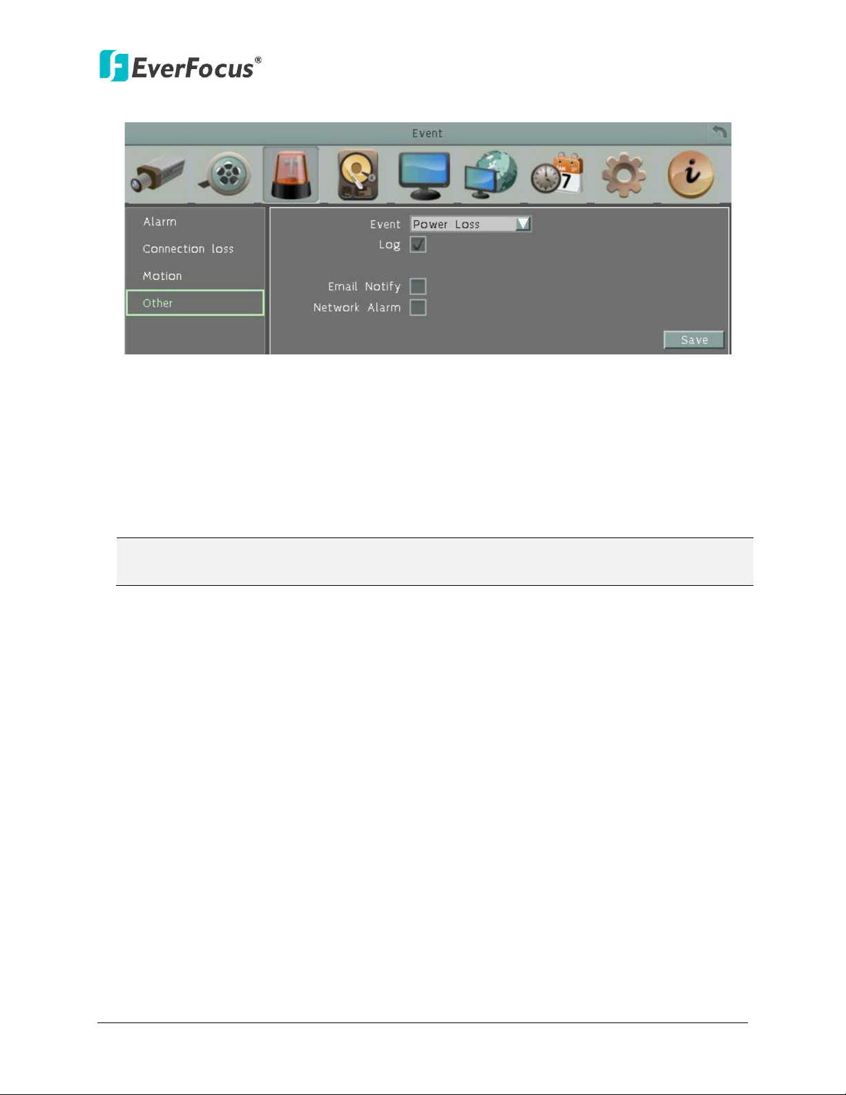
ENVR8304D-8CH
6.3.4.6 Power Loss
Figure 6-24
Log: Check the box to record alarm events to log data.
Email Notify: Check the box to send email notification when power has been restored.
Email operation requires valid email entered in the Email setup menu (see 6.6.2 Email).
Network Alarm: Check the box to send out a network alarm to a client PC when power has
been restored. This feature works with EverFocus’ CMS software. You will need to configure
the Alarm Server for the NVR to send network alarms to the client PC (see 6.6.5 Alarm
Server).
Note: As alarms and emails cannot be transmitted without power, the log entry is made
when power is restored, and any notifications cannot be made until that time.
81
Page 91
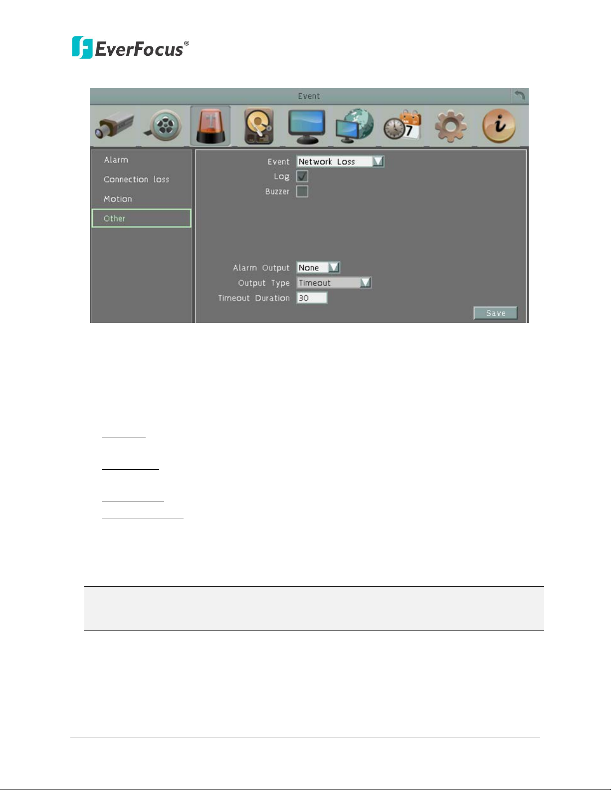
ENVR8304D-8CH
Note: This function only checks the physical connection (link) to the network. Any network
6.3.4.7 Network Loss
Figure 6-25
Log: Check the box to record alarm events to log data.
Buzzer: Check the box to enable buzzer when network is lost.
Alarm Output: Select an alarm output number. When an alarm is triggered, the signal will
be transmitted through the selected alarm output relay.
Output Type: Select an output type when the network is lost.
Timeout: Select this option and then set up the Timeout Duration in the field below, the
alarm output will last for the setup duration time (10 ~ 150 seconds).
Permanent: Alarm will remain active until the user presses the “Enter” key on the IR
Remote Control or resets the alarm remotely.
Transparent: Alarm output remains as long as the alarm input is active.
Trans + Timeout: Alarm output continues until event ends, then continues for the setup
duration time (10 ~ 150 seconds).
Timeout Duration: This function only appears when you select Timeout or Trans + Timeout
options in the Output Type drop-down list. Select a duration time for the event. The alarm
output will last for the setup duration time between 10 and 150 seconds.
behavior that blocks data connectivity (blocked ports, IP addressing errors, etc.) is not
detected by this function.
82
Page 92

ENVR8304D-8CH
6.4 Disk
The Disk menu is used to review the NVR’s hard drive settings and status. No value in this menu
can be configured by the operator.
6.4.1 Disk
Figure 6-26
Record Time (Start): Shows the earliest recording time of the NVR.
Record Time (End): Shows the latest or most current time on the NVR.
Disk: Select a disk number.
Health Status: Displays the current status of the selected disk.
Disk Temperature: Displays the current temperature of the selected disk.
Disk Size (Total): Shows the total space of the selected disk.
Disk Size (Usage): Shows the used space of the selected disk.
83
Page 93
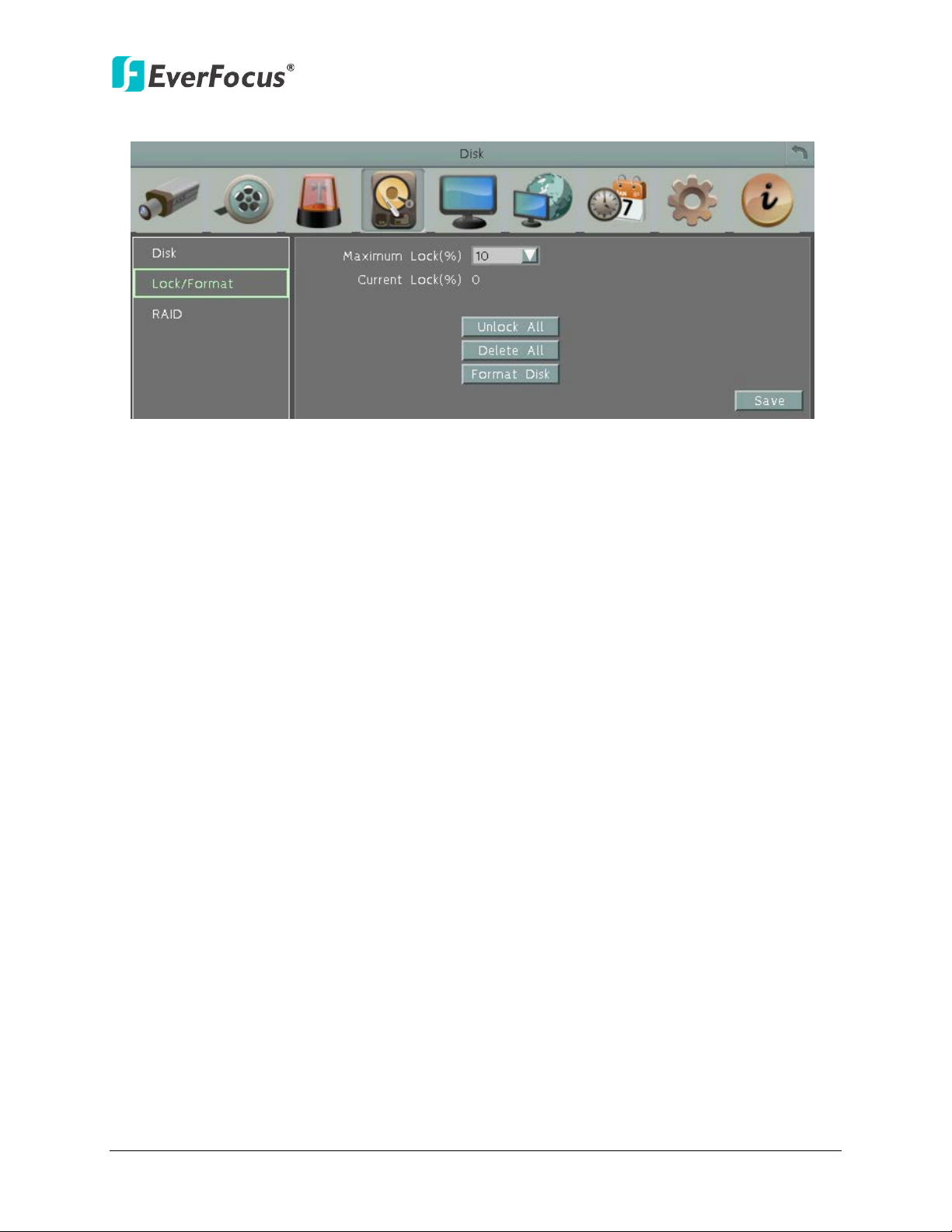
ENVR8304D-8CH
6.4.2 Lock / Format
Figure 6-27
Maximum Lock (%): Sets the maximum percentage of the hard disk space reserved for Locked
Event Recordings. To set up the Locked Event Recordings, please select the Auto Lock item in
6.4.3 Motion or 6.4.1 Alarm.
Current Lock (%): Displays the current percentage of the locked event recordings in the hard disk.
If the amount of locked event recordings has reached the maximum lock percentage, the NVR
will be unable to lock new event recordings.
Unlock All: Click this button to unlock the locked part of hard disk.
Delete All: Click this button to delete all the unlocked data in the hard disk. WARNING: This will
effectively ERASE the hard disk’s contents, except for the locked portion.
Format Disk: Click this button to format the whole HDD. WARNING: This will effectively ERASE
the ENTIRE hard disk!!
84
Page 94
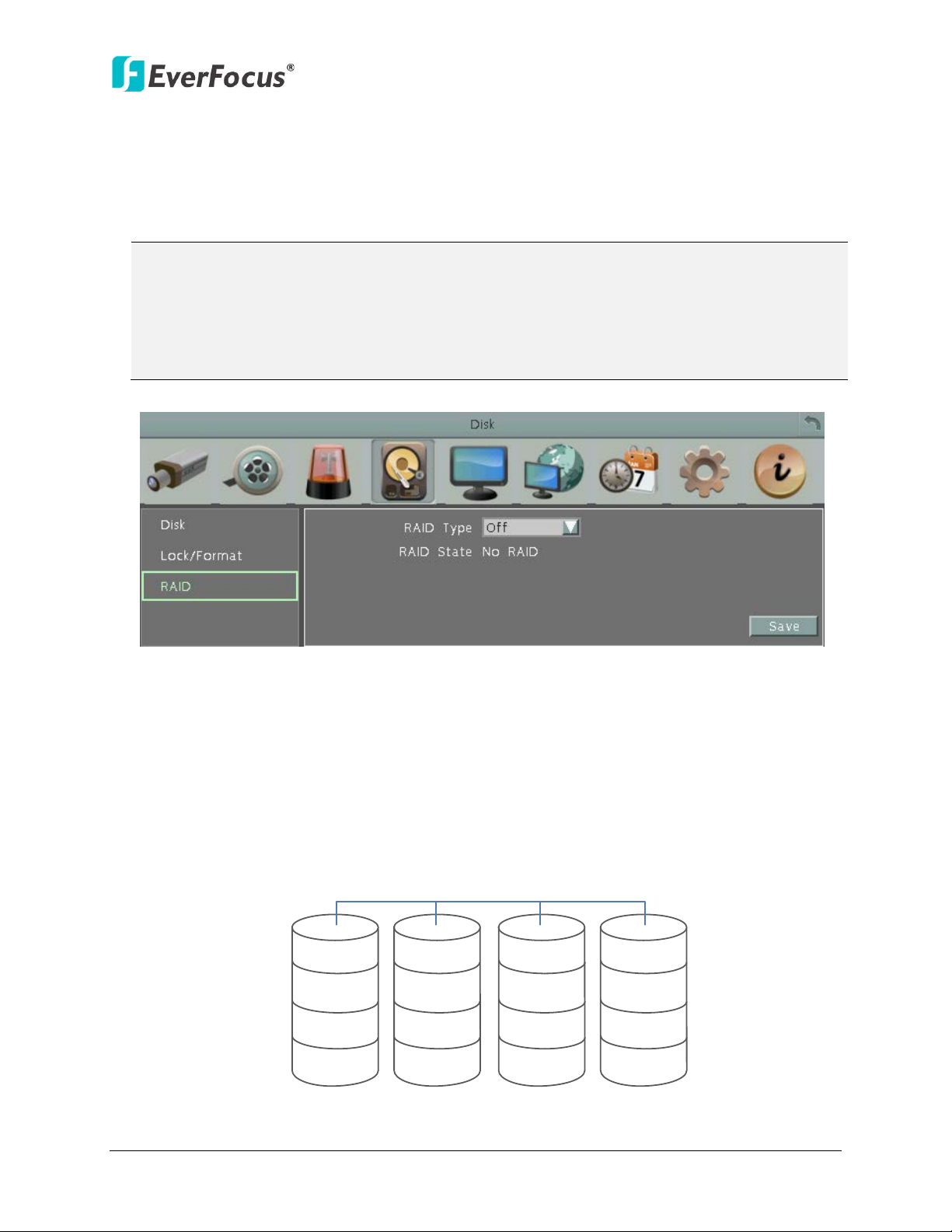
ENVR8304D-8CH
NVR will reboot the NVR automatically.
A1
B1
C
1
D
p
A2
B2
C
p
D1
A3
B
p
C
2
D2
A
p
B3
C3
D3
RAID 5
6.4.3 RAID
The RAID function (Redundant Arrays of Independent Disks) can enable multiple hard disks
to act as one, and the data will be spread out over the disks in one of several ways which are
called “RAID levels”. The NVR only supports RAID 5, which can increase disk read and write
speed, offer fault tolerance and provide efficient use of storage space.
Note:
1. To establish a RAID 5 volume, a minimum of three HDDs are required.
2. It’s highly recommended to use enterprise level and anti-rotational vibration HDDs with
the same Brand, Model and Capacity.
3. Hot swapping function is not supported. Removing the HDDs without powering off the
Figure 6-28
RAID Type:
Off: No RAID.
RAID 5: It takes at least three HDDs to build up a RAID 5, and only one of the HDDs will be
used for recovering data while the rest of the HDDs will be used for data storage purpose.
Hence, the RAID 5 array will not be destroyed by a single drive failure because the system
can recover the data on the remaining disks. However, if more than one disk fail, the data
will be missed and cannot be recovered.
85
Page 95
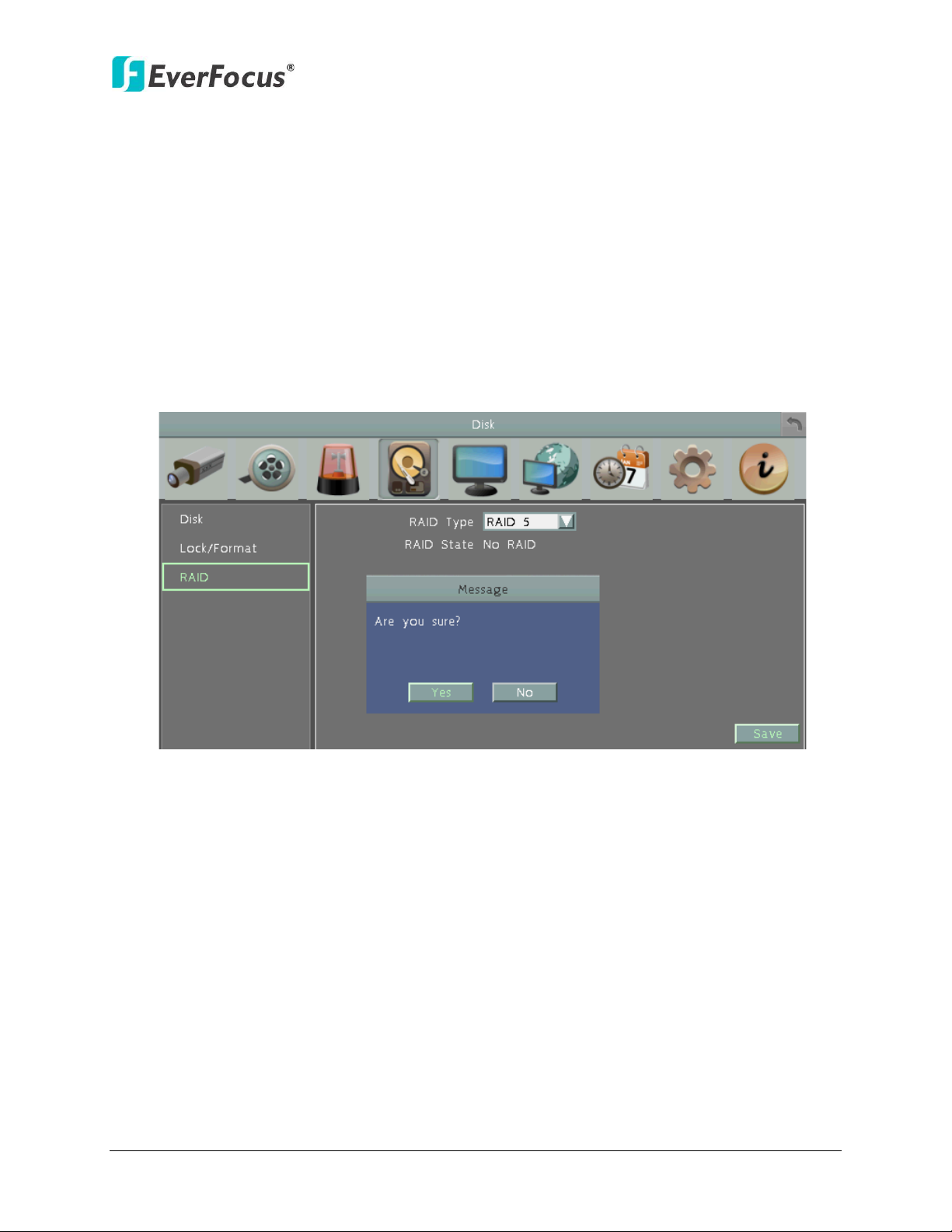
ENVR8304D-8CH
The total capacity of a RAID 5 array is the size of the smallest disk times (N-1) disks. For
example, a RAID 5 volume with three 200 GB disks and one 100 GB disk will have a total
capacity of 300 GB. {100 GB x (4-1) = 300 GB}.
RAID State: Shows the RAID and disk state. (No RAID, Broken, Degrade, Rebuilding, Normal,
EzBackup, Unknown, or System Error, No RAID Now. If connecting to more than one disk, it
will show Disk1, Disk2 …DiskX is ok.)
To enable the RAID 5 function, follow the steps below:
1. Select RAID 6, the following message appears. Click Yes to configure the RAID settings.
And the NVR will automatically reboot.
Figure 6-29
2. Enter the RAID menu again, the RAID 5 is enabled.
86
Page 96

ENVR8304D-8CH
6.5 Display Setting
You can configure the settings for displaying the camera / NVR information on the live view
image. You can also set up the sequencing order for the Main / Call monitor.
6.5.1 Monitor OSD
Figure 6-30
Title: Check the box to display camera titles.
Date/Time: Check the box to display current date/time.
Event Status: Check the box to display event status.
HDD Status: Check the box to display hard drive status.
Playback Date/Time: Check the box to display playback date/time (only for main monitor).
Playback Status: Check the box to display playback status (only for main monitor).
Text Insert: Check the box to display text inserted.
Screen Mode: Select the suitable screen mode. Selections are: 1920x1080; 1280x1024;
1024x768; 800x600. Please see to 2.3.4 Display Aspect Ratio for more details.
87
Page 97

ENVR8304D-8CH
6.5.2 M/T SEQ
You can configure up to 20 steps of the sequencing order for the Main / Call monitor. The
Sequence will repeat continuously from step 1 to step 20 until interrupted.
Figure 6-31
Monitor: Select Main or Call Monitor to configure the sequencing order.
Step: The sequencing order.
Camera: Select a camera for the specific step.
Dwell (sec): Sets up the dwell time between 0 and 60 seconds for each step.
88
Page 98

ENVR8304D-8CH
Note: Since every Network Configuration is different, please check with your Network
6.6 Network
The NVR allows you to use a Web browser to remotely view and manage the system. You can
also receive live video streaming from the NVR using your smartphone.
Administrator or ISP to see if your NVR should use specific IP addresses and/or port
numbers.
6.6.1 LAN & WAN
According to your network environment, select Static IP, DHCP or PPPoE to configure an IP
address to the NVR.
Figure 6-32
Port Type: There are two port types. The LAN (POE) port is for connecting the PoE device.
The WLAN (WAN) port is for connecting the NVR to the network. Please select WLAN (WAN)
to further configure the Network Type of the NVR.
Install: Check the box to enable the network connection.
Network Type: Three options are selectable: Static IP, DHCP and PPPoE.
89
Page 99

ENVR8304D-8CH
Static IP: User can set a fixed IP for network connection.
DHCP: DHCP server in LAN will automatically assign an IP configuration for the network
connection.
PPPoE: For direct connection to the DSL only. Verify with your ISP if they use PPPoE.
IP address: Displays the NVR’s current IP Address. A static IP address must be set manually.
If DHCP is selected, this value will be assigned automatically.
Subnet Mask: Displays the subnet mask for your network so the NVR will be recognized
within the network. If DHCP is selected, this value will be assigned automatically.
Gateway: Displays the gateway on your network for the NVR to use when communicating
with any devices not on the local network. If DHCP is selected, this value will be assigned
automatically.
DNS Server 1: Displays the primary DNS server for your network. If DHCP is selected and an
internet connection is available, this value should be assigned automatically. This field
must have a valid DNS address in order to use the DDNS feature (see 6.6.3 DDNS).
DNS Server 2: This field shows the secondary DNS server for your network.
HTTP Port: Port number for HTTP/WEB communication.
Bandwidth Limit (Kbps): Specify, disabled / 128 K/ 256 K / 512 K / 768K / 1M / 3M bps. This
is the maximum bandwidth that the NVR is allowed to use on the network. This is a useful
function when connecting the NVR to busy or heavily loaded networks, or when accessing
the NVR(s) over a WAN.
Connect: Click to test the network connection.
Additional information:
1. Set up the NVR Network Menu according to the instructions detailed in the Networking
chapter of this NVR’s manual.
a. If using DHCP, all settings will be detected automatically. While DHCP is a useful
tool for determining the network settings, if you set up your NVR in this manner its
IP address may change at different times for different reasons, particularly after a
power failure. If the IP address of the NVR changes, you may have difficulties
accessing your NVR locally and/or remotely. It is strongly recommended that you
assign a fixed (static) IP address to your NVR, and that in order to avoid address
conflicts the IP address assigned be outside of the DHCP range of addresses your
router issues to DHCP clients. Please do not set the DHCP address issued to the NVR
by the router as its static IP address unless you take specific steps that program
your router to prevent such address conflicts.
b. If using a Fixed IP (recommended), you will need to input the information manually.
In order for DDNS to work, you must enter valid data, compatible with your
network, for all four of the network setting fields: IP address, subnet mask, default
gateway and the DNS Address (depending on your network hardware and IP
90
Page 100

ENVR8304D-8CH
configuration this may be the IP address of your router/gateway, or it may be the
actual IP address of the local DNS server). The DNS server IP is required because
your DNS server provides critical information necessary for the NVR to
communicate with the DDNS server.
You can obtain the actual DNS IP from your Internet Service Provider (ISP); or, from a PC
located on the same LAN as the NVR, go to http://www.dnsserverlist.org/ to obtain a list of
the IP addresses of their recommendation of the best servers to use for your location.
2. If you are connecting through a router, make sure that you have ‘opened up’ all the
required network ports in the port forwarding section of your router’s setup options.
That is, you have directed the router to send any incoming traffic using those IP ports
to the LAN IP address of the NVR. Useful information about router port forwarding can
be found at www.portforward.com . Different routers may use different terms for port
forwarding function. For instance, D-Link calls it virtual server, Netopia calls it pinholes.
The default port for the NVR is: 80
Note: Port 80 is the default port used for Web browsing. Because of this, in order to
prevent the average user from hosting a Web server, most ISPs BLOCK traffic using port
80 from reaching the average site. If you only plan to view your NVR on a LAN, you can
use port 80, and don’t have to concern yourself with DDNS or routers. However, if you
desire remote access to your NVR, perhaps using DDNS (optional), you MUST select
functional ports and set up the port forwarding in your router. Other ports, such as
8080 and 8000 are sometimes blocked by ISPs as well.
What port(s) should be used? There are 65,535 valid IP ports to choose from. These are
broken down into three groups:
• Well Known Ports 0 thru 1023
• Registered Ports 1024 thru 49151
• Dynamic and/or Private Ports 49152 thru 65535
So, rather than encounter a port conflict by choosing a port commonly used for
another purpose (like port 25 for SMTP mail or port 448 for secure sockets), choose an
‘unusual’ port number. For example, add 50,000 to your house number: 50,123 is less
likely to lead to a port conflict. For a list of the known and registered ports, see
http://www.iana.org/assignments/port-numbers
91
 Loading...