

EverFocus ENVR8304D, ENVR8304E User Manual
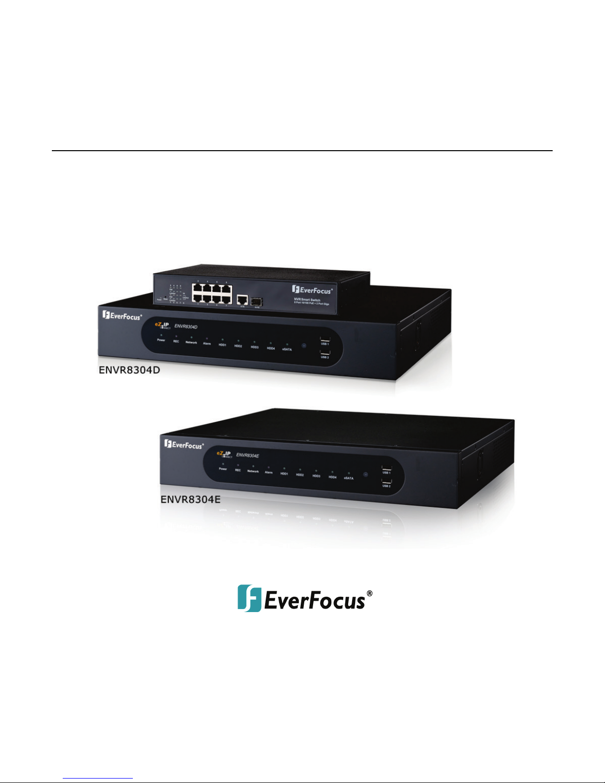
ENVR8304D / ENVR8304E
ENVR8304D-8CH / ENVR8304E-8CH, Plug & Play NVR
User’s Manual
Notice: This content is subject to be changed without notice.
Copyright © EverFocus Electronics Corp,
Release Date: May 2014

EVERFOCUS ELECTRONICS CORPORATION
ENVR8304D-8CH / ENVR8304E-8CH
User’s Manual
1995-2014 EverFocus Electronics Corp
www.everfocus.com
All rights reserved. No part of the contents of this manual may be reproduced or transmitted in any form
or by any means without written permission of the EverFocus Electronics Corporation.
Release Date: May, 2014
QuickTime is a registered trademark of the Apple Computer, Inc.
Windows is a registered trademark of the Microsoft Corporation.
Linksys is a registered trademark of the Linksys Corporation.
D-Link is a registered trademark of the D-Link Corporation.
DynDNS is a registered trademark of the DynDNS.org Corporation.
Other product and company names mentioned herein may be the trademarks of their respective owners.

Safety Precautions
Refer all work related to the installation of this product to qualified service personnel or
system installers.
Do not block the ventilation openings or slots on the cover.
Do not drop metallic parts through slots. This could permanently damage the appliance.
Turn the power off immediately and contact qualified service personnel for service.
Do not attempt to disassemble the appliance. To prevent electric shock, do not remove
screws or covers. There are no user-serviceable parts inside. Contact qualified service
personnel for maintenance. Handle the appliance with care. Do not strike or shake, as this
may damage the appliance.
Do not expose the appliance to water or moisture, nor try to operate it in wet areas. Do
take immediate action if the appliance becomes wet. Turn the power off and refer servicing
to qualified service personnel. Moisture may damage the appliance and also may cause
electric shock.
Do not use strong or abrasive detergents when cleaning the appliance body. Use a dry cloth
to clean the appliance when it is dirty. When the dirt is hard to remove, use a mild
detergent and wipe gently.
Do not overload outlets and extension cords as this may result in a risk of fire or electric
shock.
Do not operate the appliance beyond its specified temperature, humidity or power source
ratings. Do not use the appliance in an extreme environment where high temperature or
high humidity exists. Use the NVR at temperatures within 0°C~40°C / 32°F~104°F (Storage).
The input power source is 100-240 VAC~ / 150W max.
Read Instructions
All the safety and operating instructions should be read before the unit is operated.
Retain Instructions
The safety and operating instructions should be retained for future reference.
Heed Warnings
All warnings on the unit and in the operating instructions should be adhered to.
ii

ATTENTION! This is a class A product which may cause radio interference in a
Follow Instructions
All operating and use instructions should be followed.
Cleaning
Unplug the unit from the outlet before cleaning. Do not use liquid cleaners, abrasive or
aerosol cleaners. Use a damp cloth for cleaning
Attachments
Do not use attachments not recommended by the product manufacturer as they may
cause hazards.
Water and Moisture
Do not use this unit near water-for example, near a bath tub, wash bowl, kitchen sink, or
laundry tub, in a wet basement, near a swimming pool, in an unprotected outdoor
installation, or any area which is classified as a wet location.
Servicing
Do not attempt to service this unit by yourself as opening or removing covers may expose
you to dangerous voltage or other hazards. Refer all servicing to qualified service
personnel.
Power Cord Protection
Power supply cords should be routed so that they are not likely to be walked on or pinched
by items placed upon or against them, playing particular attention to cords and plugs,
convenience receptacles, and the point where they exit from the appliance.
Object and Liquid Entry
Never push objects of any kind into this unit through openings as they may touch
dangerous voltage points or short-out parts that could result in a fire or electric shock.
Never spill liquid of any kind on the unit.
Battery
Risk of explosion if battery is replaced by an incorrect type. Dispose of used batteries
according to the instructions.
a. Use only two AAA dry cell batteries.
b. Do not dispose of the batteries in a fire as it may explode.
domestic environment; in this case, the user may be urged to take adequate measures.
iii

This Product is RoHS compliant.
Federal Communication Commission Interference Statement
WEEE
The information in this manual was current upon publication. The manufacturer reserves the right
This product complies with the High-Definition Multimedia Interface (HDMI)
This equipment has been tested and found to comply with the limits for a Class B digital
device, pursuant to Part 15 of the FCC Rules. These limits are designed to provide
reasonable protection against harmful interference in a residential installation. This
equipment generates, uses and can radiate radio frequency energy and, if not installed
and used in accordance with the instructions, may cause harmful interference to radio
communications. However, there is no guarantee that interference will not occur in a
particular installation. If this equipment does cause harmful interference to radio or
television reception, which can be determined by turning the equipment off and on, the
user is encouraged to try to correct the interference by one of the following measures:
•Reorient or relocate the receiving antenna.
•Increase the separation between the equipment and receiver.
•Connect the equipment into an outlet on a circuit different from that to which the
receiver is connected.
•Consult the dealer or an experienced radio/TV technician for help.
FCC Caution: Any changes or modifications not expressly approved by the party
responsible for compliance could void the users’ authority to operate this equipment.
Your EverFocus product is designed and manufactured with high quality materials and
components which can be recycled and reused. This symbol means that electrical and
electronic equipment, at their end-of-life, should be disposed of separately from your
household waste. Please, dispose of this equipment at your local community waste
collection/recycling centre. In the European Union there are separate collection systems
for used electrical and electronic product.
Please, help us to conserve the environment we live in!
Specification Adopter Agreement.
to revise and improve his products. Therefore, all specifications are subject to change without prior
notice. Manufacturer is not responsible for misprints or typographical errors.
Please read this manual carefully before installing and using this unit. Be sure to keep it handy for
later reference.
iv

TABLE OF CONTENTS
1. Introduction ................................................................................................................... 1
1.1 Overview ........................................................................................................................ 2
1.2 Features ......................................................................................................................... 4
1.3 Packing List ..................................................................................................................... 5
1.4 Optional Accessories ...................................................................................................... 6
1.5 Front Panel ..................................................................................................................... 7
1.6 Rear Panel ...................................................................................................................... 8
2. Installation ................................................................................................................... 10
2.1 Hard Disk Drive Installation ......................................................................................... 10
2.1.1 Hard Disk Compatibility List .............................................................................. 12
2.2 Rack Mount .................................................................................................................. 13
2.3 Basic Connection .......................................................................................................... 14
2.3.1 Camera Connection ........................................................................................... 16
2.3.2 Cable Length Extension ..................................................................................... 17
2.3.3 Monitor Connection .......................................................................................... 18
2.3.4 Display Aspect Ratio .......................................................................................... 19
2.3.5 Alarm I/O ........................................................................................................... 20
2.3.6 RS-485 Port........................................................................................................ 21
2.3.7 RS-232 Port........................................................................................................ 21
2.4 Turning On / Off the Power ......................................................................................... 21
2.5 Connecting the NVR to the Network ........................................................................... 22
2.5.1 Router or LAN Connection ................................................................................ 22
2.5.2 Direct High-Speed Connection .......................................................................... 25
2.5.3 One-to-One Connection .................................................................................... 26
2.6 Checking the Dynamic IP Address ................................................................................ 30
3. General Operation ........................................................................................................ 33
3.1 Login ............................................................................................................................. 33
3.2 Forget Your Password .................................................................................................. 34
3.3 Opening OSD Root Menu ............................................................................................. 34
3.4 Field Input Option ........................................................................................................ 35
3.5 Camera Selection ......................................................................................................... 36
3.6 Enabling Audio ............................................................................................................. 36
4. OSD Root Menu ............................................................................................................ 37
4.1 PTZ ................................................................................................................................ 39
4.1.1 Express Control of PTZ ...................................................................................... 41
v

4.2 Layout Switching .......................................................................................................... 42
4.3 Channel Switching ........................................................................................................ 42
4.4 Display .......................................................................................................................... 43
4.5 Sequence ...................................................................................................................... 44
4.6 Zoom ............................................................................................................................ 44
4.7 Archiving the Recordings or Log Data to the USB........................................................ 46
4.8 Logout .......................................................................................................................... 49
5. Search and Playback ..................................................................................................... 50
5.1 Quick Playback ............................................................................................................. 50
5.2 Playback Bar ................................................................................................................. 51
5.3 Searching the Recordings for Playing Back .................................................................. 53
5.3.1 Time Search ....................................................................................................... 53
5.3.2 Event Search ...................................................................................................... 54
5.3.3 Snapshot Search ................................................................................................ 55
6. Configuration ................................................................................................................ 57
6.1 Camera ......................................................................................................................... 59
6.1.1 Camera Status ................................................................................................... 59
6.1.2 Basic .................................................................................................................. 60
6.1.3 PTZ ..................................................................................................................... 62
6.1.4 Tracking ............................................................................................................. 65
6.1.5 Pattern Tour ...................................................................................................... 67
6.1.6 Adjust ................................................................................................................ 69
6.1.7 eZ Hopper .......................................................................................................... 71
6.2 Record & Playback ....................................................................................................... 74
6.2.1 Record ............................................................................................................... 74
6.2.2 Quick Archive .................................................................................................... 75
6.2.3 Playback ............................................................................................................ 76
6.3 Event ............................................................................................................................ 77
6.3.1 Alarm ................................................................................................................. 77
6.3.2 Connection Loss ................................................................................................ 79
6.3.3 Motion ............................................................................................................... 81
6.3.4 Other ................................................................................................................. 84
6.3.4.1 Fan Failure ........................................................................................................ 84
6.3.4.2 Disk Temperature ............................................................................................ 85
6.3.4.3 Disk Failure ....................................................................................................... 86
6.3.4.4 Disk Full ............................................................................................................ 87
6.3.4.5 Disk Off ............................................................................................................. 88
6.3.4.6 Power Loss ....................................................................................................... 89
6.3.4.7 Network Loss .................................................................................................... 90
6.4 Disk ............................................................................................................................... 91
vi

6.4.1 Disk .................................................................................................................... 91
6.4.2 Lock / Format .................................................................................................... 92
6.4.3 RAID ................................................................................................................... 93
6.5 Display Setting.............................................................................................................. 95
6.5.1 Monitor OSD ..................................................................................................... 95
6.5.2 M/T SEQ ............................................................................................................ 96
6.6 Network ....................................................................................................................... 97
6.6.1 LAN & WAN ....................................................................................................... 97
6.6.2 Email ................................................................................................................ 100
6.6.3 DDNS ............................................................................................................... 101
6.6.3.1 EverFocus DDNS ............................................................................................. 102
6.6.3.2 www.dyndns.org ............................................................................................ 103
6.6.4 FTP ................................................................................................................... 104
6.6.5 Alarm Server .................................................................................................... 105
6.6.6 Network Test ................................................................................................... 106
6.7 Schedule ..................................................................................................................... 107
6.7.1 Express Setup .................................................................................................. 107
6.7.2 Holidays ........................................................................................................... 108
6.7.3 Schedule .......................................................................................................... 109
6.8 System Setting ........................................................................................................... 112
6.8.1 Date/Time ....................................................................................................... 112
6.8.2 Daylight Saving ................................................................................................ 114
6.8.3 User Group ...................................................................................................... 115
6.8.4 User Management .......................................................................................... 116
6.8.5 I/O Control ...................................................................................................... 119
6.8.6 EKB200 Setting ................................................................................................ 121
6.8.7 Miscellaneous ................................................................................................. 123
6.9 System Information ................................................................................................... 125
6.9.1 Configuration .................................................................................................. 125
6.9.2 Log ................................................................................................................... 127
7. Remote Access to the NVR .......................................................................................... 128
7.1 Accessing the NVR...................................................................................................... 128
7.2 Install JAVA Runtime .................................................................................................. 130
7.3 Browser Security Setting ............................................................................................ 132
7.3.1 Installing ActiveX Controls .............................................................................. 132
7.3.2 Enabling ActiveX Controls ............................................................................... 133
7.4 Remote Live View ...................................................................................................... 136
7.5 Camera ....................................................................................................................... 139
7.5.1 Camera Status ................................................................................................. 139
7.5.2 Basic ................................................................................................................ 140
vii

7.5.2.1 Camera ........................................................................................................... 140
7.5.2.2 PTZ .................................................................................................................. 142
7.5.3 Video Adjust .................................................................................................... 149
7.6 PTZ .............................................................................................................................. 151
8. Specifications.............................................................................................................. 153
8.1 ENVR8304D-8CH / ENVR8304D-8CH ......................................................................... 153
8.2 NVR Smart Switch for ENVR8304D ............................................................................ 155
8.3 Embedded PoE of ENVR8304E ................................................................................... 157
Appendix A: Network Overview ......................................................................................... 159
Appendix B: Linksys & D-Link Port Forwarding ................................................................... 163
Appendix C: IR Remote Control .......................................................................................... 167
viii

ENVR8304D-8CH / ENVR8304E-8CH
1
Chapter
1. Introduction
EverFocus all new NVR Solution, targeting small-scale installations such as homes and small
businesses, will also be placed under the spotlight. With true plug-and-play setup and real-time
local display up to Full HD resolution, the Linux-embedded solution works just like a NVR but
without the need for those complicated network settings that would be otherwise required
with conventional NVR systems.
Featuring a standalone network video recorder up to 8 channels, along with a series of NVR
EverFocus megapixel cameras, the NVR Solution offers a complete system kit that can be easily
installed in a matter of minutes. There is no need to purchase extra computers or software to
operate the system.
When paired with our powerful EverFocus PowerVideo Plus CMS, the ENVR8304D-8CH /
ENVR8304E-8CH can be used in complex multi-site installations with centralized management.
The ENVR8304E-8CH is also fully supported by the EverFocus MobileFocus remote viewer on
iOS and Android devices, which help extend video surveillance from fixed locations to mobile
environments.
EverFocus also introduces an innovative function, eZ Hopper, for our new series of DVRs / NVRs,
allowing users to control up to 16 connected DVRs / NVRs with just one single mouse. This
breakthrough feature brings great benefits to the traditional small and medium-sized
surveillance system, not only eliminating the expense of the central monitoring software, but
also saving the setup cost and time.
1

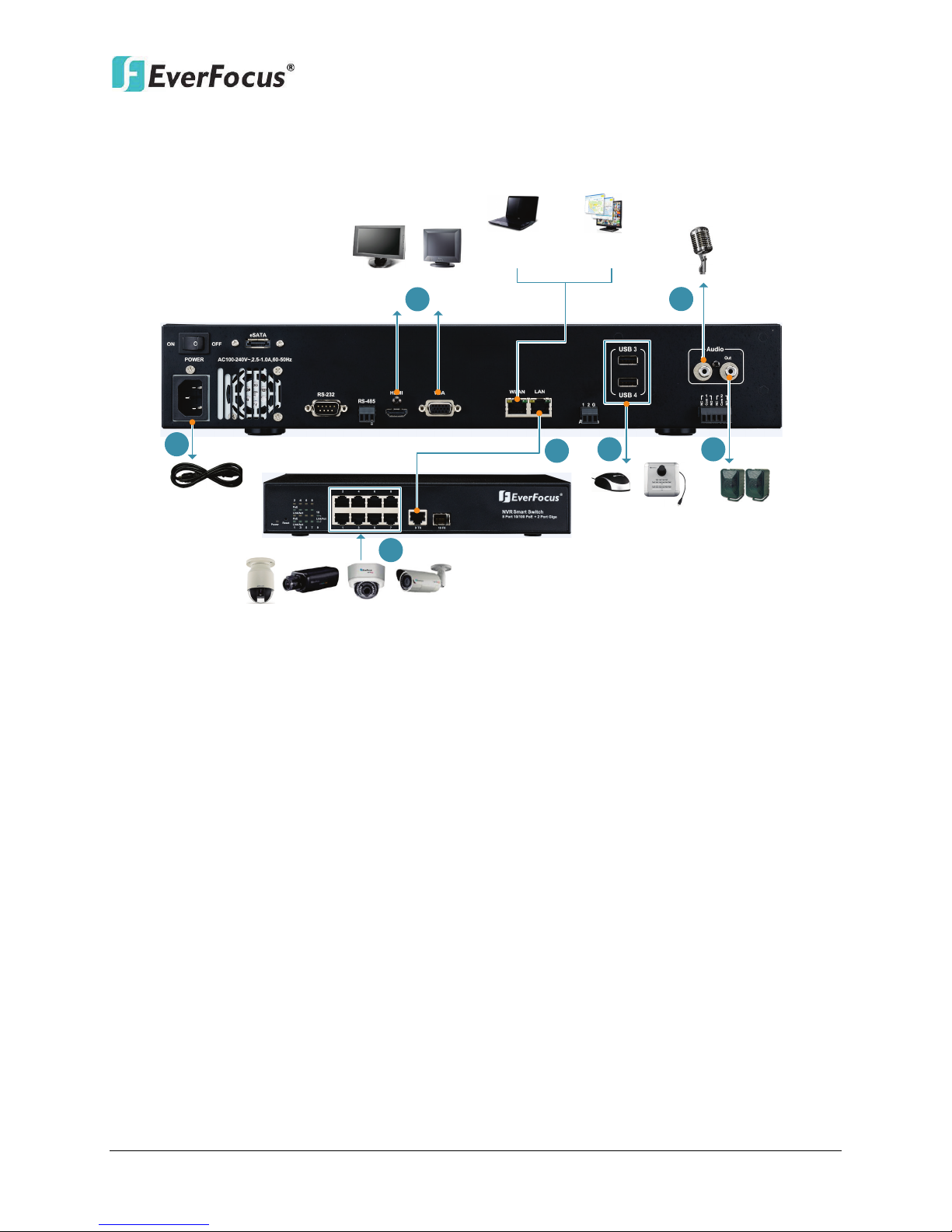
1.1 Overview
Front View
3.5
" HDD
Mouse or
USB Memory StickIR Remote Control
Rear View
Power Cord
RS-232
Data Input
RS-485 Device
Main Monitor
(HDMI)
Main Monitor
(VGA)
Web Remote
Client
PowerVideo Plus
(CMS)
Network
EKB200
Keyborad
Line Level
Audio In
Alarm In
/ Out
Line Level
Audio Out
eSATA HDD
Expansion
(EDA450
)
NVR Smart Switch
IP Cameras 1 ~ 8
ENVR8304D:
ENVR8304D-8CH / ENVR8304E-8CH
Figure 1-1
2
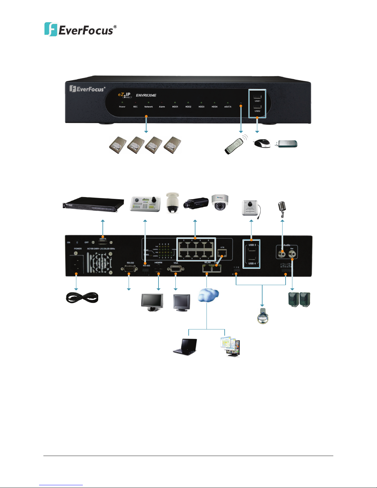
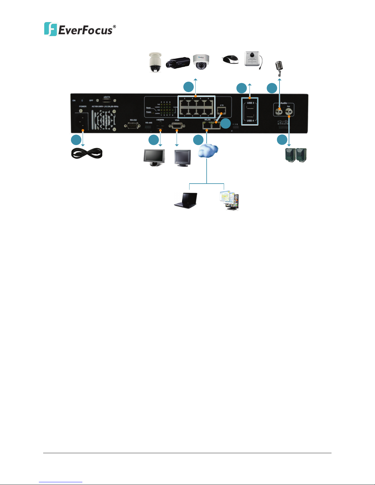
ENVR8304E:
Front View
3.5" HDD
Mouse or
USB Memory StickIR Remote Control
Rear View
Power Cord
RS-232
Data Input
RS-485 Device
Main Monitor
(HDMI)
Main Monitor
(VGA)
Web Remote
Client
PowerVideo
Plus
(CMS)
Network
EKB200
Keyborad
Line Level
Audio In
Alarm In / Out
Line Level
Audio Out
eSATA HDD
Expansion
(EDA450)
IP Cameras 1 ~ 8
ENVR8304D-8CH / ENVR8304E-8CH
Figure 1-2
3

ENVR8304D-8CH / ENVR8304E-8CH
1.2 Features
• 8-channel real-time recording and playback at 1080p resolution
• Build-in 8 PoE ports (ENVR8304E only)
• Support megapixel IP cameras
• The Plug and Play design simplifies installation and configuration
• H.264 compression format for enhancing recording capacity and improving network
image transmission speed
• eZ Hopper: Only one mouse to control up to 16 connected EverFocus DVRs/NVRs
• Separately configured HDMI or VGA (1080p) monitor outputs
• High bandwidth 1080p recording (200 / 240fps) with recordable reduced bandwidth
stream for mobile or multiplexed viewing applications
• RAID5 – for full data protection
• Free EverFocus DDNS Service – static IP address is not required for reliable remote access
• Supports one eSATA port for external HDD (optional:EDA450)
• Supports live monitoring and playback of video from mobile devices via MobileFocus /
MobileFocus Plus Apps
• Multiple control inputs: mouse / remote controller / EKB500 and EKB200 keyboards
• Multiple intelligent video query functionality, including snapshot and smart search
• Powerful archive functionality from both remote and NVR sites
• Simplified access to common features such as setup, archival, playback and search
functions through express menus
• Remote configuration support from built-in web interface
• Gigabit Ethernet interface for remote network viewing and control
• Integration with PowerVideo Plus
• Multi-language support
• 19” Rack mountable – rack ears included
4
ENVR8304D-8CH / ENVR8304E-8CH
•
•
•
•
•
•
•
•
•
•
•
•
• Only for ENVR8304D: NVR Smart Switch x 1, Power Cord x 1, CD x 1 (Please see Note 6.)
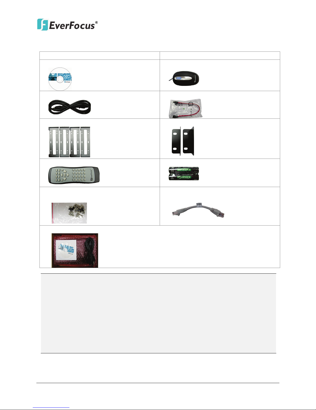
1.3 Packing List
NVR x 1
CD x 1 (Please see Note 3.)
Power Cord x 1
HDD Bracket x 4
IR Remote Control x 1
Sliver Screw x 16, Washer Head Screw x 8,
M3 (φ6.8) Screw x 4
User Manual x 1
Mouse x 1
SATA Cable x 4
Rack Ear x 2
AAA Battery x 2 (Please see Note 4.)
Only for ENVR8304E: RJ45 CAT5 Cable x1
(Please see Note 5.)
Note:
1. Equipment configurations and supplied accessories vary by country. Please consult
your local EverFocus office or agents for more information. Please also keep the
shipping carton for possible future use.
2. Contact the shipper if any items appear to have been damaged in the shipping process.
3. The CD contains the IP Utility software, User Manual and Quick Installation Guide.
4. Risk of explosion if battery is replaced by an incorrect type. Dispose of used batteries
according to the instructions.
5
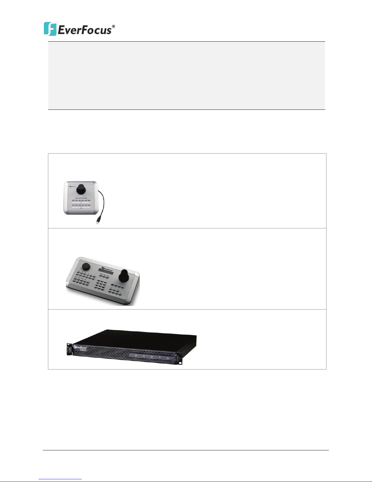
ENVR8304D-8CH / ENVR8304E-8CH
• EKB200 (USB controller keyboard: connect to the PC or the NVR to control the PTZ
•
• EDA450 (eSATA Storage Device: connect to the eSATA port of the NVR). Please refer to
a. Use only two AAA dry cell batteries.
b. Do not dispose of the batteries in a fire as it may explode.
5. Be sure to use this cable to connect the LAN port to the Uplink port (9TX) of the NVR,
please see 2.3 Basic Connection.
6. These three items are packed in a box, and the CD contains the User Manual of the
NVR Smart Switch.
1.4 Optional Accessories
cameras connected to the NVR). Please refer to 6.8.6 EKB200 Setting and the User
Manual of the EKB200 Keyboard.
EKB500 (RS-485 keyboard: connect to the RS-485 port to control the PTZ cameras
connected to the NVR). Please refer to 6.1 Camera and the User Manual of the EKB500
Keyboard.
No. 2, Figure 1-3.
6
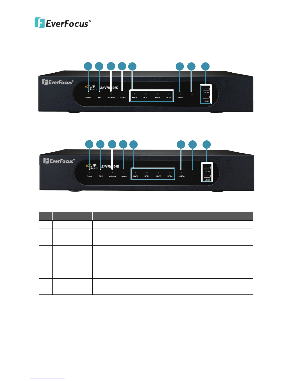
1.5 Front Panel
1
2 3 4
5
8
7
6
1
2
3
4
5
8
7
6
ENVR8304D:
ENVR8304E:
ENVR8304D-8CH / ENVR8304E-8CH
No. Name Description
1 Power
2 REC
3 LAN
4 Alarm
5 HDD1~4
6 eSATA
7 IR Receiver
8 USB1 / USB2
Indicates the power is on.
Indicates the NVR is recording.
Indicates the NVR is connected to the network.
Indicates an alarm input is triggered.
Separately indicates the internal HDD 1~4 is activating.
Indicates the external HDD is activating.
Receiver for signals from the IR remote control.
USB2.0 ports for connecting to a mouse, external storage device,
or EKB200 keyboard.
Figure 1-2
7
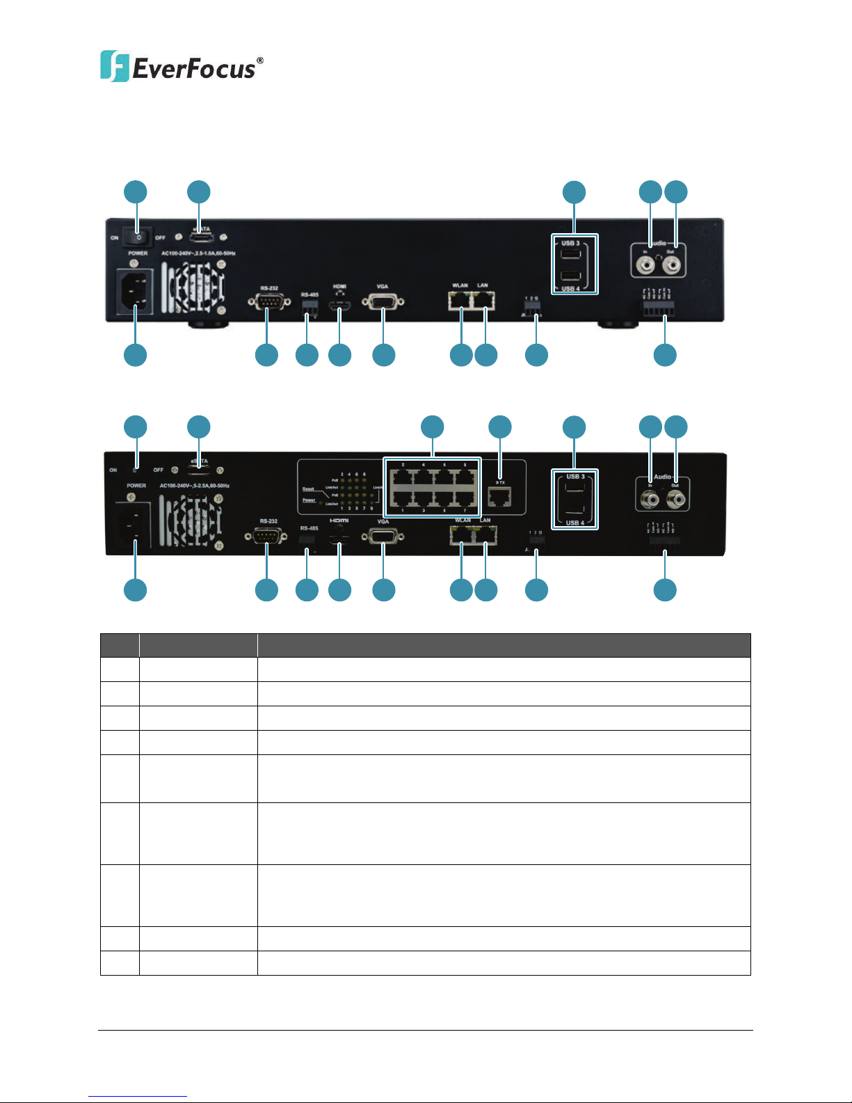
1.6 Rear Panel
1 2
8
5
6 7
9 10 11 12 13 1514
16
1
2
3
4
8
5
6
7
9
10
11 12
13 15
14
16
Connects to the audio input devices, such as microphones. Note that
are required.
Connects to the audio output devices, such as speakers. Note that the
ENVR8304D:
ENVR8304E:
ENVR8304D-8CH / ENVR8304E-8CH
No. Name Description
1 Power
2 eSATA Port
3 PoE Port 1~8
4 Uplink Port
5 USB3 / USB4
Audio Input
6
(RCA socket)
Audio Output
7
(RCA socket)
8 Power Port
9 RS-232 Port
Press to turn On / Off the NVR.
Connects to an external eSATA storage device. (EDA450)
Connects to 8 IP cameras without extra power supply.
Connects to the LAN port of the NVR using the supplied RJ-45 Cable.
The USB2.0 ports for connecting to a mouse, external storage device
or EKB200 keyboard.
the microphone with a (built-in) amplifier and external power supply
speaker with a (built-in) amplifier and external power supply are
required.
Connects to the 100-240 VAC~ power using the supplied Power Cord.
Connects to the RS-232 device. Please refer to 2.3.7 RS-232 Port.
Figure 1-3
8

ENVR8304D-8CH / ENVR8304E-8CH
Connects to the RS-485 device, such as EverFocus’ EKB-500 keyboard.
Connects to the Main monitor using a HDMI cable. Please refer to
Connects to the Main monitor using a VGA cable. Please refer to 2.3.3
Connects to the network using a standard RJ-45 CAT5 10/100Mb
ENVR8304D: Connects to the Uplink Port of a PoE device using a
10 RS-485 Port
11 HDMI Port
12 VGA Port
13 WLAN
14 LAN
15 Alarm Input
16 Alarm Output
Please refer to 2.3.6 RS-485 Port.
2.3.3 Monitor Connection.
Monitor Connection.
Ethernet cable. Please refer to 2.5 Connecting the NVR to the
Network.
standard RJ-45 CAT5 10/100Mb Ethernet cable. Please refer to 2.3.1
Camera Connection.
ENVR8304E: Connects to the (4) Uplink Port using the supplied RJ-45
Cable. Please refer to 2.3.1 Camera Connection.
Connects up to 2 alarm inputs. Please refer to 2.3.5 Alarm IO.
Connects to 2 alarm output devices. Please refer to 2.3.5 Alarm IO.
9
ENVR8304D-8CH / ENVR8304E-8CH
Silver Screw
HDD Bracket
2
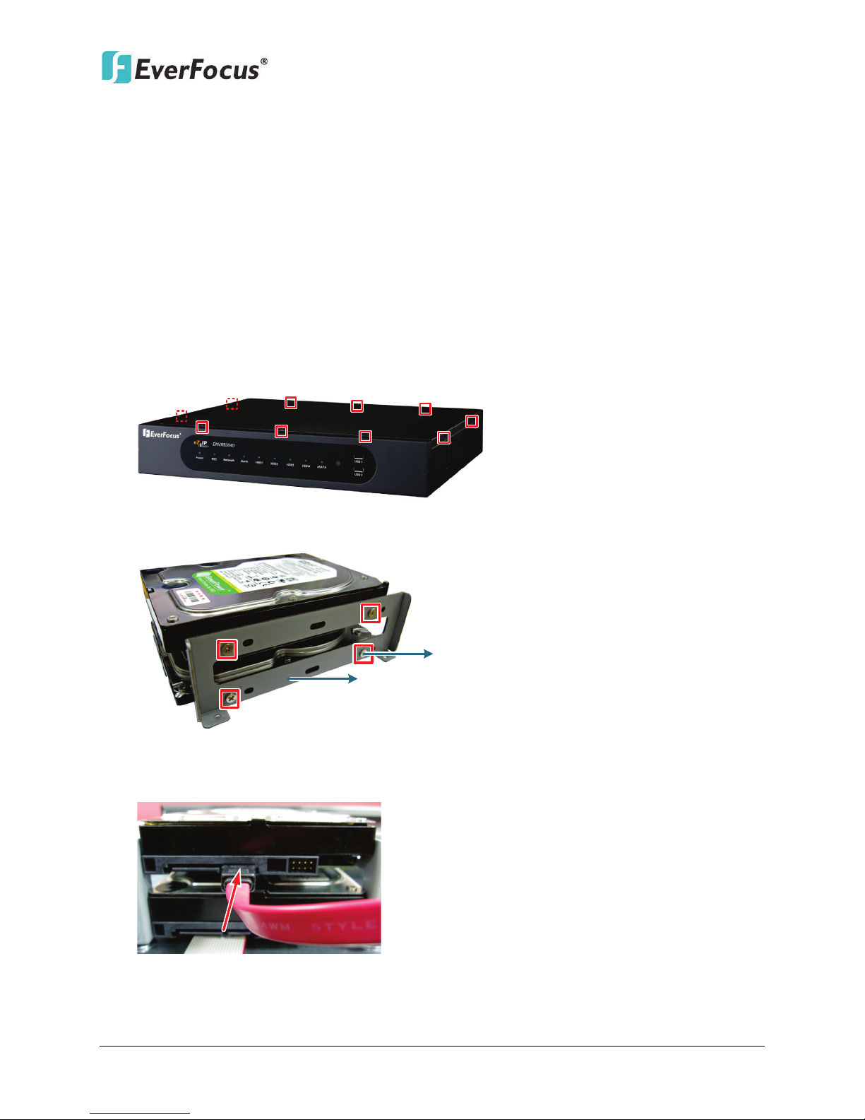
2. Installation
2.1 Hard Disk Drive Installation
1. Make sure the NVR is power-off.
2. Unscrew the ten housing screws on the NVR, and open the housing.
Chapter
Figure 2-1
3. Screw two HDD brackets on both sides of the HDDs using the Sliver Screws.
Figure 2-2
4. Use the SATA Cable, and connect one end to the SATA port on the small PCB inside the
NVR, and the other end to the SATA port on the HDD.
Figure 2-3
10
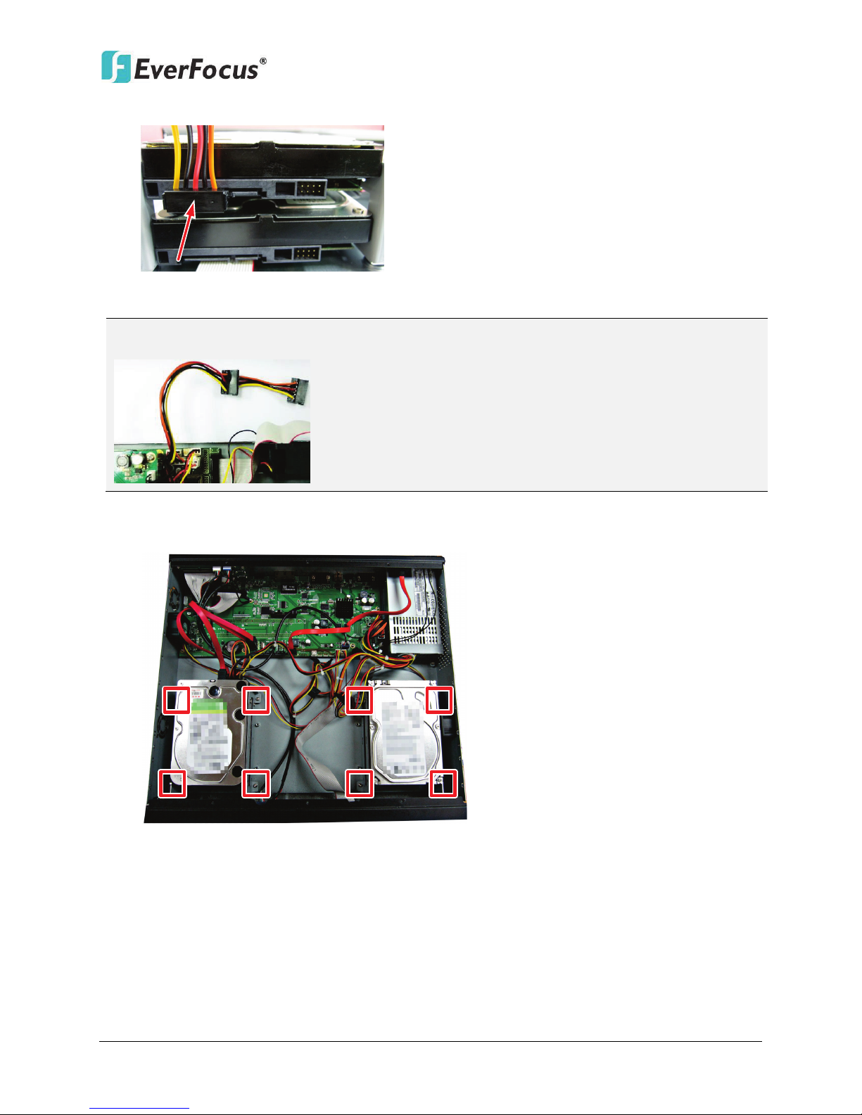
ENVR8304D-8CH / ENVR8304E-8CH
Note: The internal power cable is connected to the Main board inside the NVR. The power
5. Connect the internal power cable to the HDD.
Figure 2-4
cable features two connectors, which can be used to connect to two HDDs.
6. Screw the HDDs with the brackets inside the NVR using the Washer Head Screws.
Figure 2-5
7. Screw back the housing to the NVR.
11

ENVR8304D-8CH / ENVR8304E-8CH
SATA Hard Disk
Model
Capacity
Constellation ES.3 SATA3 ST4000NM0033
4TB
Constellation CS SED SATA3 T3000NC000
3TB
CE-Video SATA3 / ST3500312CS
500GB
CE-Video SATA3 / ST1000VM002
1TB
CE-Video SATA3 / ST2000VM003
2TB
CE-Video SATA3 / ST3000VM002
3TB
CE-Video SATA3 / ST4000VM000
4TB
ST4000VX000
4TB
SV35 SATA6 7200/ ST1000VX000
1TB
SV35 SATA6 7200/ ST2000VX000
2TB
SV35 SATA6 7200/ ST3000VX000
3TB
Constellation CS SATA3 7200 / ST1000NC000
1TB
Constellation CS SATA3 7200 / ST3000NC000
3TB
CE-Video SATA6 5900RPM / ST1000VM002
1TB
CE-Video SATA6 5900RPM / ST2000VM003
2TB
SV35 SATA3 7200/ST3000VX000
3TB
SV35 SATA3 7200/ST2000VX000
2TB
SV35 SATA3 7200/ST1000VX000
1TB
CE-Video SATA3 / ST2000VM003
2TB
CE-Video SATA3 / ST1000VM002
1TB
WD40PURX-64GVNYO
4TB
WD30PURX-64P6ZY0
3TB
WD20PURX-64P6ZY0
2TB
WD10PURX-64D85Y0
1TB
WD10EURX SATA3
1TB
WD30EURS SATA2
3TB
WD10EVVS SATA
1TB
WD20EFRX
2TB
WD30EFRX
3TB
WD4001FAEX
4TB
WD RE SATA/64MB Cache WD4000FYYZ
4TB
2.1.1 Hard Disk Compatibility List
Please use the hard disk models recommended in the list below to ensure your hard disks will
be compatible.
Seagate
Western Digital
Note: If using two or more hard disks, please choose the hard disks with the same capacity.
12

ENVR8304D-8CH / ENVR8304E-8CH
2.2 Rack Mount
To install rack ears on the NVR, use the supplied two Rack Ears and the four M3 (φ6.8) Screws
for rack mount installation on both side.
Figure 2-6
13
ENVR8304D-8CH / ENVR8304E-8CH
Power Supply
Main Monitor
(HDMI)
Main Monitor
(VGA)
Web Remote
Client
PowerVideo
Plus
(CMS)
NVR Smart Switch
Mouse &
EKB200 Keyboard
IP Cameras 1 ~ 8
EVNR8304D-8CH
4
5
1
2
Line Level
Audio In
7
Line Level
Audio Out
8
6
2.3 Basic Connection
The instructions below describe the basic connection for ENVR8304D-8CH and ENVR8304E-8CH.
ENVR8304D:
Figure 2-7
1. Using the supplied Power Cord, connect one end to the 100-240 VAC~ port on the NVR and
the other end to the 100-240 VAC~ power outlet.
2. To view videos, connect a monitor to the HDMI or VGA port using the HDMI or VGA cable
supplied by the monitor manufacturer.
3. To manage the NVR over network, use a standard RJ-45 CAT5 10/100Mb Ethernet cable to
connect the WLAN port of the NVR to the network. Please refer to 2.5 Connecting the NVR
to the Network.
4. Connect the LAN port of the NVR to the Uplink port of a PoE device using a standard RJ-45
CAT5 10/100Mb Ethernet cable. Please see 2.3.1 Camera Connection for more details.
5. Connect the IP cameras to the 1~8 camera ports at the rear of the PoE switch using
Ethernet cables without separate power sources. Please see 2.3.1 Camera Connection for
more details.
6. Optionally connect a mouse or a keyboard (EKB200) to the NVR to control the system. You
can also control the system using the supplied IR Remote Controller.
7. Connect a microphone to the Audio-in RCA socket of the NVR. Note that the microphone
with a (built-in) amplifier and external power supply is required.
8. To listen to audio of video source, connect a speaker to the Audio-out RCA socket. Note
that the speaker with a (built-in) amplifier and external power is required.
14
ENVR8304E:
Power Cord
Main Monitor
(HDMI)
Main Monitor
(VGA)
Web Remote
Client
PowerVideo Plus
(CMS)
Network
Line Level
Audio In
Line Level
Audio Out
IP Cameras 1 ~ 8
Mouse &
EKB200 Keyboard
1 2
3
4
5
6 7
8
ENVR8304D-8CH / ENVR8304E-8CH
1. Using the supplied Power Cord, connect one end to the 100-240 VAC~ port on the NVR and
the other end to the 100-240 VAC~ power outlet.
2. To view videos, connect a monitor to the HDMI or VGA port using the HDMI or VGA cable
supplied by the monitor manufacturer.
3. Connect the IP cameras to the 1~8 camera ports using RJ-45 CAT5 10/100Mb Ethernet
cables without separate power sources. Please see 2.3.1 Camera Connection for more
details.
4. To manage the NVR over network, use a standard RJ-45 CAT5 10/100/1000Mb Ethernet
cable to connect the WLAN port of the NVR to the network. Please refer to 2.5 Connecting
the NVR to the Network.
5. Connect the LAN port of the NVR to the Uplink port (9TX) using the supplied RJ-45 CAT5
10/100/1000Mb Ethernet cable. Please see 2.3.1 Camera Connection for more details.
6. Optionally connect a mouse or a keyboard (EKB200) to the NVR to control the system. You
can also control the system using the supplied IR Remote Controller.
7. Connect a microphone to the Audio-in RCA socket of the NVR. Note that the microphone
with a (built-in) amplifier and external power supply is required.
8. To listen to audio of video source, connect a speaker to the Audio-out RCA socket. Note
that the speaker with a (built-in) amplifier and external power is required.
Figure 2-8
15
ENVR8304D-8CH / ENVR8304E-8CH
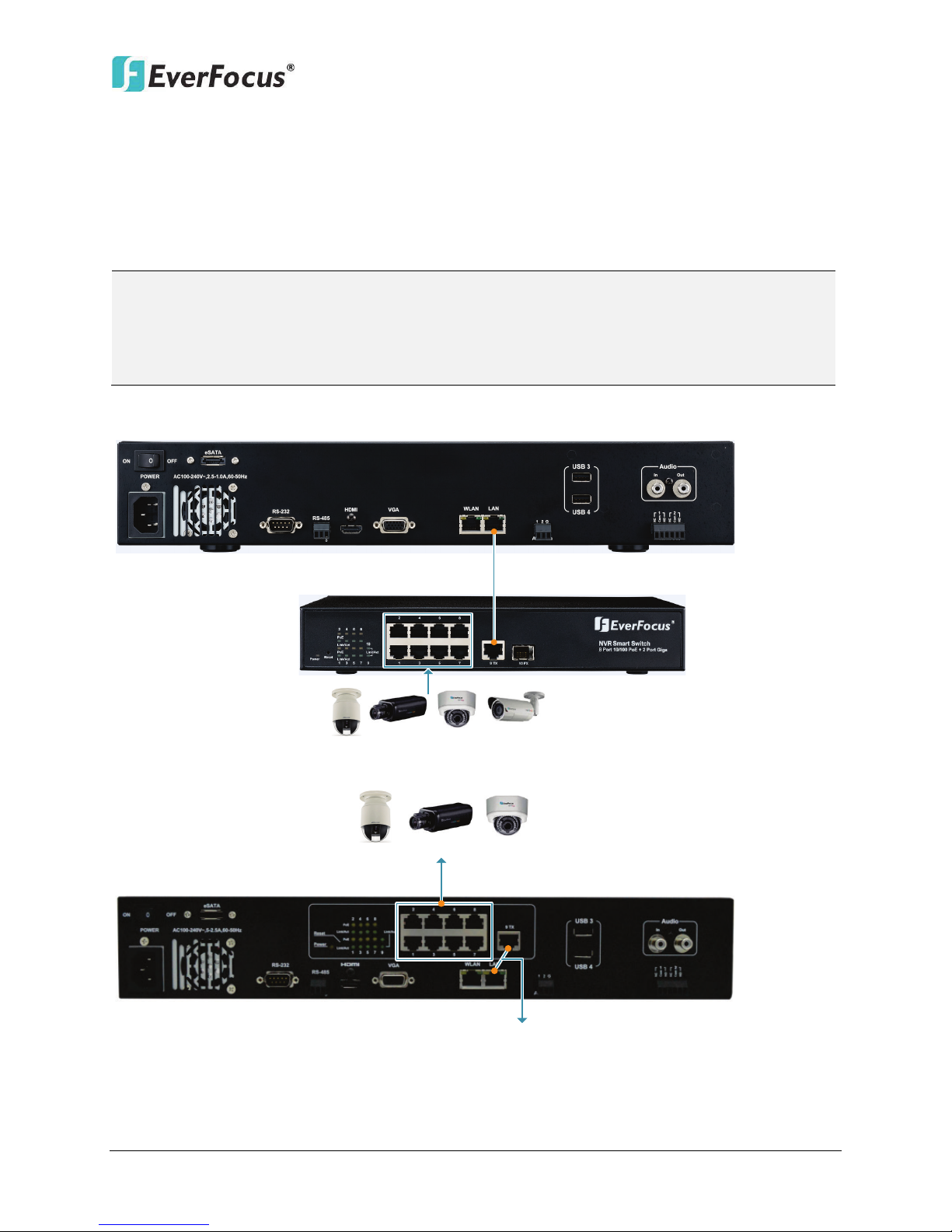
Note:
NVR Smart Switch
IP Cameras 1 ~ 8
IP Cameras 1 ~ 8
Connect the two ports using
the supplied RJ-45 Cable
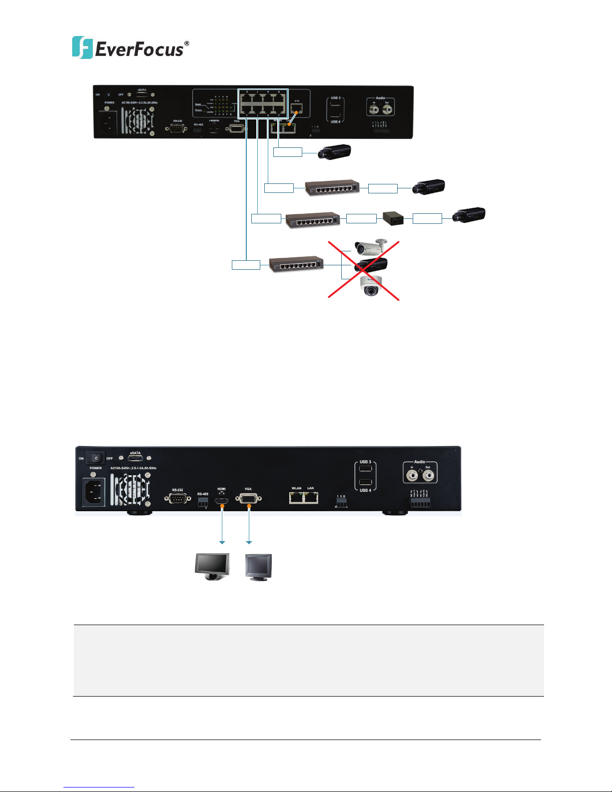
2.3.1 Camera Connection
ENVR8304D: Connect the LAN Port to the Uplink port of the PoE device (NVR Smart Switch)
using the supplied RJ-45 Cable. Connect the IP cameras to the 1~8 camera ports to the PoE port
1~8 using Ethernet cables.
ENVR8304E: Connect the LAN Port to the Uplink port of the NVR using the supplied RJ-45 Cable.
Connect the IP cameras to the 1~8 camera ports to the PoE port 1~8 using Ethernet cables
1. If the length between the PoE switch and the IP camera exceeds 100 meters, please see
2.3.2 Cable Length Extension for cable length extension instruction.
2. The total PoE power budget is 130W; please make sure the total Power Consumption of
all the connected IP cameras doesn’t exceed 130W.
ENVR8304D:
ENVR8304E:
Figure 2-9
16
ENVR8304D-8CH / ENVR8304E-8CH
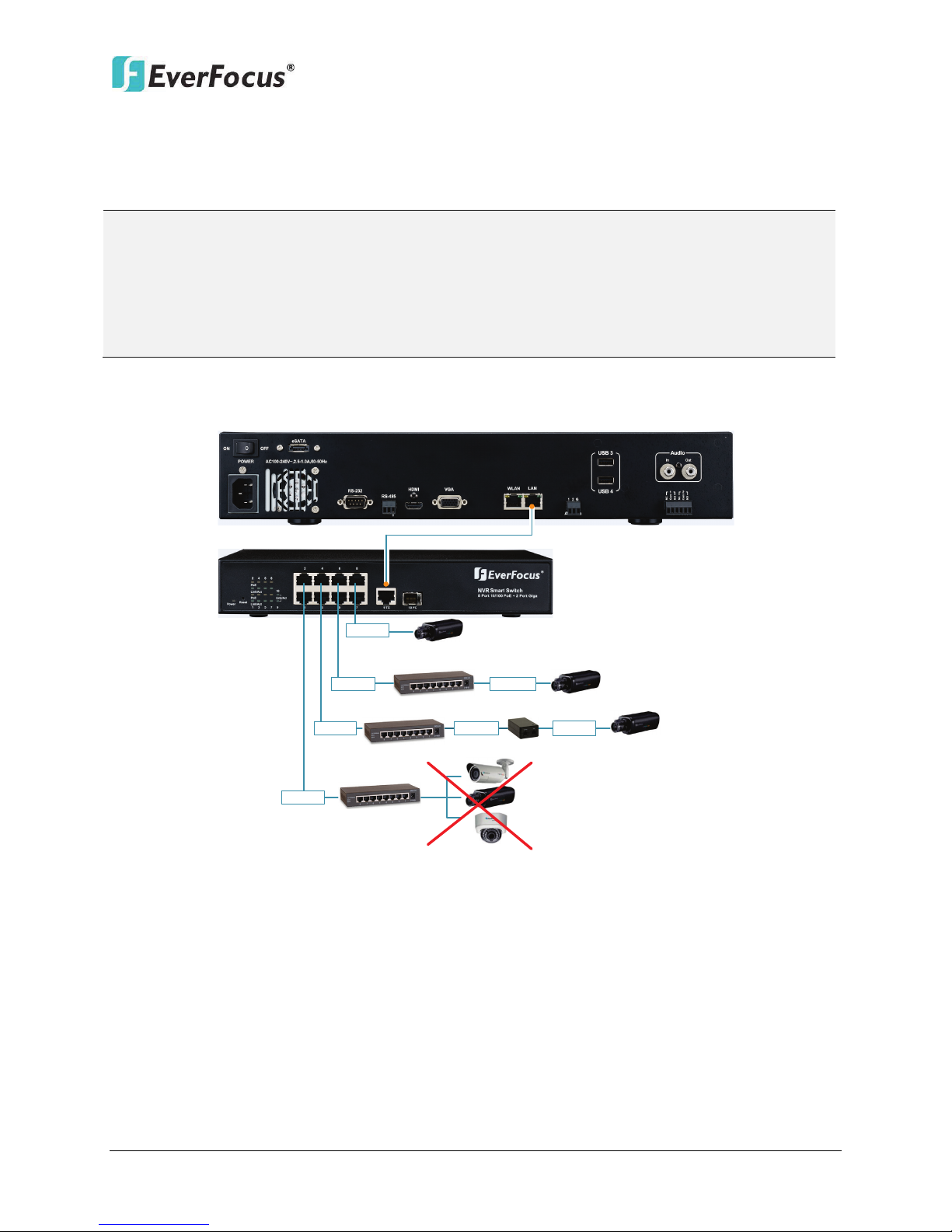
Note:
EVNR8304D
NVR Smart Switch
Hub
Hub
Hub
100 M
100 M
100 M
100 M
100 M
100 M
100 M
PoE Injector
The camera
requires separate
power supply.
Connect to one
camera only.
2.3.2 Cable Length Extension
The Ethernet connection is effective within 100 meters in distance. If the distance between the
PoE switch and the IP cameras is over 100 meters, you need to use a hub, PoE injector or PoE
extender, which should be connected to one camera only.
1. It is required to provide power supply additionally for the camera connecting by a hub
for extension.
2. For stable connection and operation, the user should establish a dedicated
communication line for IP cameras in the same network so that the router connection is
not allowed.
ENVR8304D:
Figure 2-10
17
ENVR8304E:
Hub
Hub
Hub
100 M
100 M
100 M
PoE Injector
The camera
requires separate
power supply.
Connect to one
camera only.
100 M
100 M
100 M
100 M
Main Monitor
(HDMI)
Main Monitor
(VGA)
HDMI Cable
VGA Cable
Note:
ENVR8304D-8CH / ENVR8304E-8CH
Figure 2-11
2.3.3 Monitor Connection
The NVR provides 2 main monitor outputs with identical functionality - VGA and HDMI. You can
connect the monitor to the VGA or HDMI port on the rear panel of the NVR. Both of the VGA
and HDMI video outputs can be used simultaneously and deliver full HD resolution (1920 x 1080,
progressive, 60 Hz. Vert., 68 KHz hor.).
This figure uses ENVR8304D as an example.
Figure 2-12
1. The connected monitors’ specifications must comply with the resolution requirements.
2. Do not exceed the max. HDMI cable length of 15 meters.
3. The standard HDMI cables can support cable length up to 3 meters. For longer distances, such
as 15 meters, it is highly recommended to use high quality HDMI cables.
18
ENVR8304D-8CH / ENVR8304E-8CH
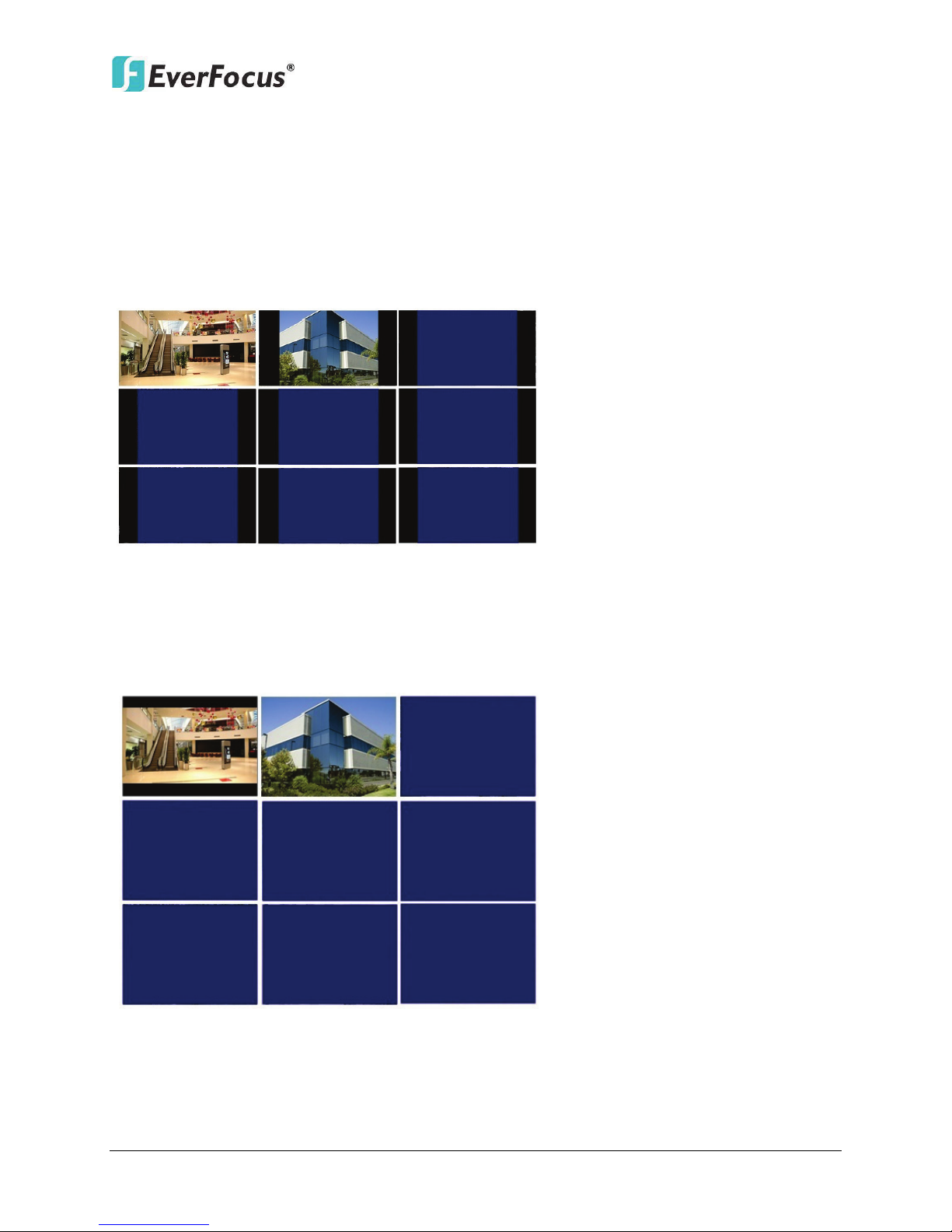
Screen Mode: 1920x1080 (16:9)
Camera Ratio: 16:9
Camera Ratio: 4:3
Screen Mode:
800
x600
/ 1024x768 /1280
x1024
(
4:
3)
Camera Ratio
:
16:9
Camera Ratio: 4
:
3
2.3.4 Display Aspect Ratio
It is recommended to select the same ratio of the screen resolution and the camera live view
display to avoid black bars showing on the live view screen as the images below.
If you select 1920x1080 (16:9) screen resolution in the Screen Mode drop-down list (see 6.5.1
Monitor OSD), it is recommended to also change the camera live view display to 16:9 aspect
ratio in the Ratio drop-down list (see 6.1.6 Adjust).
If selecting 800x600, 1024x768 or 1280x1024 (4:3) screen resolution in the Screen Mode
drop-down list (see 6.5.1 Monitor OSD), it is recommended to also change the camera live view
display to 4:3 aspect ratio in the Ratio drop-down list (see 6.1.6 Adjust).
Figure 2-13
Figure 2-14
19
ENVR8304D-8CH / ENVR8304E-8CH
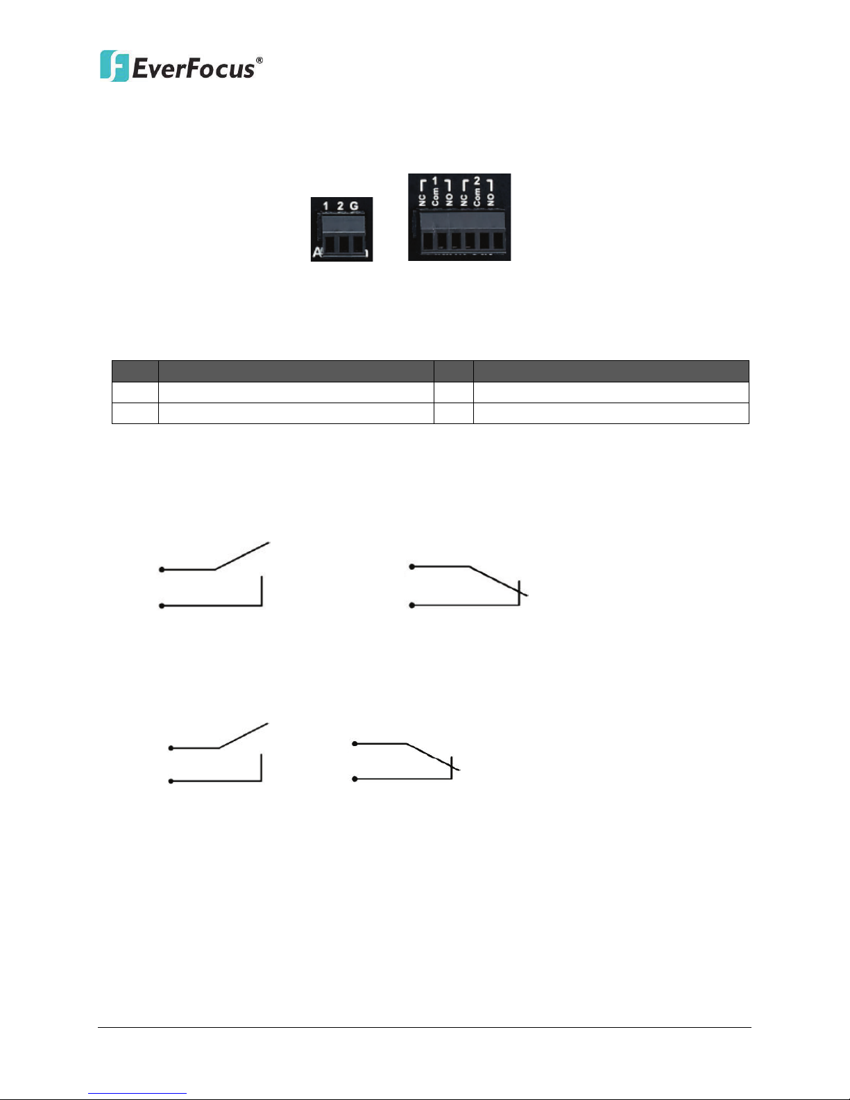
Alarm In
Alarm Out
No.
Description
No.
Description
1
ALM_IN1
2
ALM_IN2
G
GND
ALMIN
GND
ALMIN
GND
Alarm Input with N.O. contact in idle state Alarm Input with N.C. contact in idle state
ALMOUT
+
ALMOUT -
ALMOUT +
ALMOUT -
2.3.5 Alarm I/O
The NVR provides two alarm inputs and two alarm outputs. Please refer to the table below for
PIN assignment.
Figure 2-15
Alarm Input
Alarm Input Contacts
This NVR provides one alarm input per camera. All
inputs are programmable N.O. (Normal Open) or N.C. (Normal Closed). All settings are
programmed in the ALARM / Event menu.
Alarm Output Contacts
The relay output provides either Normally Open or Normally Closed dry contacts.
20
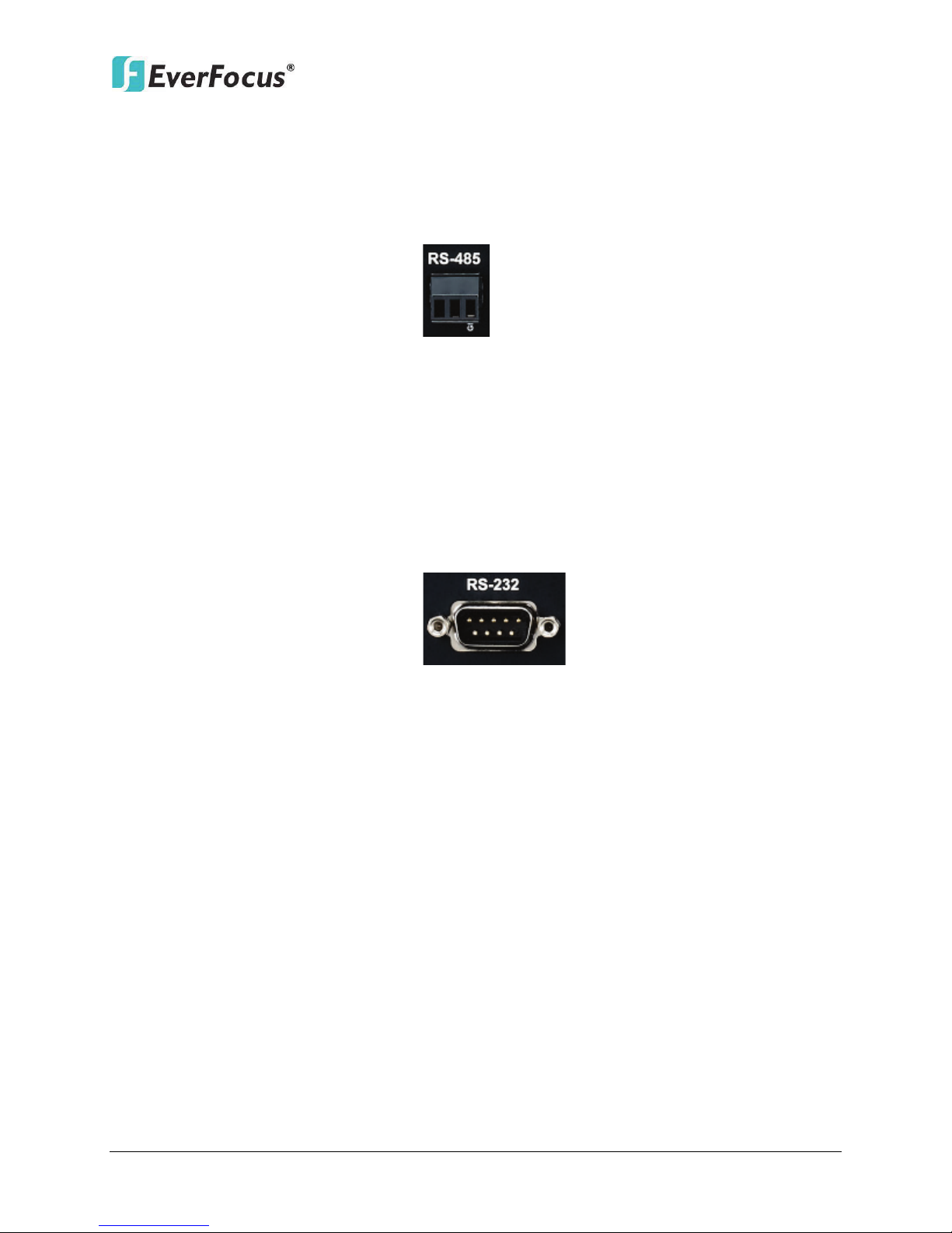
ENVR8304D-8CH / ENVR8304E-8CH
+ -
G
2.3.6 RS-485 Port
The RS-485 port, located on the rear panel of the NVR, can be used to connect to an RS-485
keyboard, such as EverFocus’ EKB500, for controlling NVR and HD PTZ cameras. For details on
the RS-485 configurations on the NVR, please refer to 6.8.5 I/O Control. The RS-485 pin
assignment is as follows:
Figure 2-16
2.3.7 RS-232 Port
The RS-232 port, located on the rear panel of the NVR, can be used to connect to an RS-232
data input device such as POS system. The RS-232 port of the NVR is a 9 pin D-Sub socket. For
details on the RS-232 configurations on the NVR, please refer to 6.8.5 I/O Control.
Figure 2-17
2.4 Turning On / Off the Power
Before powering on the NVR, please make sure the internal HDDs have been installed properly.
When you have completed the basic cable connections, you are ready to turn on the NVR.
To turn on the power, connect the supplied Power Cord to the power outlet and turn on the Power
Switch.
REC LED will remain light up. After hearing 1 beeps from the NVR, you can start operating. To
turn off the power, simply unplug the Power Cord from the power outlet. You can also press the
Power Switch on the rear panel to turn on and off the NVR without unplugging the Power Cord.
All of the LED indicators on the front panel will light up for a second, but the Power and
21
 Loading...