

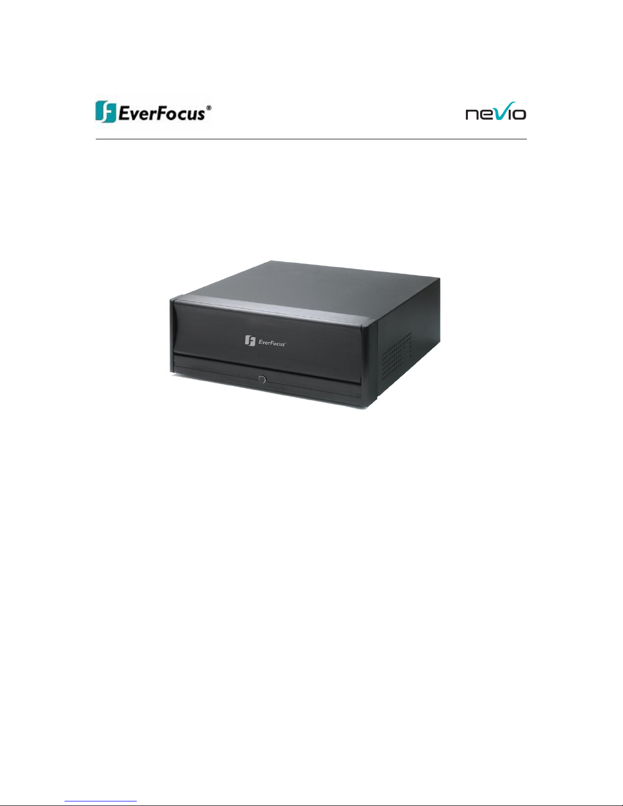
EverFocus ENR 400 Installation Manual
IInnssttaallllaattiioonn MMaannuuaall
EENNRR 440000
NNeettwwoorrkk VViiddeeoo RReeccoorrddeerr

ENR 400 Installation Manual
2 of 81 ENR400_ma_inst_en_rev01
Safety Precautions
• To avoid any damage, please consider the following safety warnings:
• Never place the recorder near to heaters, furnaces, other heat sources or under direct solar
irradiation.
• Operate the device only in locations providing the tolerable operating temperature range
0°C~40°C/32°F ~ +104°F.
• Make sure that the device‘s ventilation slots are not covered or sheeted.
• For cleaning, make sure the device is plugged off and only use a damp cloth without acid detergent.
• Install the device only in dry and dustproof surroundings. Protect the device against any liquid‘s
penetration.
• Avoid the penetration of any artefacts, e.g. through ventilation slots.
• Do not attempt to disassemble the appliance. To prevent electric shock, do not remove screws or
covers. There are no user-serviceable parts inside. Contact qualified service personnel for
maintenance. Handle the appliance with care. Do not strike or shake, as this may damage the
appliance.
• Do not operate appliance with other than specified power supplies. The input power source of the
power supply is 100 ~ 240 VAC.
• Avoid any affection of the device through vibrations or mechanical shock at the recorder‘s installation
location.
• Avoid to power off NVR by the backside power switch or disconnecting power cable during
operation.
ATTENTION! This is a class A product which may cause radio interference in a domestic environment; in
this case, the user may be urged to take adequate measures.
Your EverFocus product is designed and manufactured
with high quality materials and components which can
be recycled and reused.
This symbol means that electrical and electronic
equipment, at their end-of-life, should be disposed of
separately from your household waste.
Please, dispose of this equipment at your local
community waste collection/recycling centre.
In the European Union there are separate collection
systems for used electrical and electronic product.
Please, help us to conserve the environment we live in!
Ihr EverFocus Produkt wurde entwickelt und
hergestellt mit qualitativ hochwertigen Materialien
und Komponenten, die recycelt und wieder
verwendet werden können.
Dieses Symbol bedeutet, dass elektrische und
elektronische Geräte am Ende ihrer Nutzungsdauer
vom Hausmüll getrennt entsorgt werden sollen.
Bitte entsorgen Sie dieses Gerät bei Ihrer örtlichen
kommunalen Sammelstelle oder im Recycling
Centre.
Helfen Sie uns bitte, die Umwelt zu erhalten, in der
wir leben!
This Product is RoHS compliant.
WEE
The information in this manual was current upon publication. The manufacturer reserves the right to revise and
improve his products. Therefore, all specifications are subject to change without prior notice. Misprints reserved.
Please read this manual carefully before installing and using this unit. Be sure to keep it handy for later
reference.

ENR 400 Installation Manual
3 of 81 ENR400_ma_inst_en_rev01
CONTENT
1 INTRODUCTION ..................................................................................................................................... 5
2 MAIN FEATURES ................................................................................................................................... 5
3 SPECIFICATIONS .................................................................................................................................. 6
3.1 TECHNICAL DATA .................................................................................................................................. 6
3.2 SUPPORTED CAMERA MODELS* ............................................................................................................ 7
3.3 DIMENSIONS ........................................................................................................................................ 8
3.4 DELIVERY SCOPE ................................................................................................................................. 8
3.5 OPTIONAL ACCESSORIES ...................................................................................................................... 8
4 HARDWARE INSTALLATION ................................................................................................................ 9
4.1 FRONT PANEL CONTROLS AND CONNECTORS ......................................................................................... 9
4.2 BACK PANEL CONNECTORS .................................................................................................................. 9
4.3 STATUS LED GIGABIT LAN PORT ........................................................................................................ 10
4.4 SYSTEM CONNECTIONS ....................................................................................................................... 10
5 SYSTEM SETUP ................................................................................................................................... 11
5.1 FIRST TIME SYSTEM START ................................................................................................................ 11
5.2 MAIN CONSOLE SCREEN CONTROLS..................................................................................................... 11
5.3 QUICK START SETUP .......................................................................................................................... 12
5.4 DETAILED SETUP ............................................................................................................................... 18
5.4.1 Setting - General ........................................................................................................................................................... 18
5.4.2 Setting - Camera ........................................................................................................................................................... 20
5.4.3 Setting - I/O Device ....................................................................................................................................................... 26
5.4.4 Setting - PTZ - Config .................................................................................................................................................... 27
5.4.5 Setting - Hotline (communication settings) ................................................................................................................... 28
5.4.6 Setting - User Account .................................................................................................................................................. 29
5.4.7 Setting - Address book .................................................................................................................................................. 30
5.4.8 Setting - Monitor display ................................................................................................................................................ 30
5.4.9 Setting - Joystick ........................................................................................................................................................... 31
5.5 GUARD - LIVE EVENT / EVENT ACTION CONFIGURATION ........................................................................ 33
5.5.1 Event types .................................................................................................................................................................... 34
5.5.2 Event actions ................................................................................................................................................................. 46
5.6 SCHEDULE SETUP .............................................................................................................................. 52
5.6.1 Setup new schedule manually ....................................................................................................................................... 53
5.6.2 Copy Schedule .............................................................................................................................................................. 54
5.6.3 3.5 Week Mode ............................................................................................................................................................. 54
5.6.4 Conigure - Encoding Option Panel ............................................................................................................................... 56
5.7 E-MAP .............................................................................................................................................. 57
5.8 COUNTING APPLICATION ............................................................................................................. 59
5.9 NETWORK SERVICES .......................................................................................................................... 61
5.9.1 Network service: Live Streaming ................................................................................................................................... 61
5.9.2 Network Service: Remote Playback .............................................................................................................................. 64
5.9.3 Network Service: Remote Playback .............................................................................................................................. 65
5.9.4 Network Service: Remote Playback .............................................................................................................................. 67
5.9.5 Network Service: 3GPP Service .................................................................................................................................... 68
5.9.6 Network Service: Remote Desktop ............................................................................................................................... 69
5.9.7 Network Service: Central Management ......................................................................................................................... 69
6 APPENDIX A: DB TOOL ...................................................................................................................... 70
6.1 REPAIR DATABASE ............................................................................................................................. 71
6.2 EXPORT CONFIGURATIONS ................................................................................................................. 74

ENR 400 Installation Manual
4 of 81 ENR400_ma_inst_en_rev01
7 APPENDIX B: 3 GPP SETUP EXAMPLES .......................................................................................... 75
7.1 CONFIGURATION IN ENR .................................................................................................................... 75
7.2 CONFIGURATION MOBILE PHONE ......................................................................................................... 76
7.2.1 BenQ-Siemens E81 ....................................................................................................................................................... 76
7.2.2 BenQ P50 ...................................................................................................................................................................... 78
8 APPENDIX C: INSTALLATION REMOTE DESKTOP TOOL ............................................................... 81

ENR 400 Installation Manual
5 of 81 ENR400_ma_inst_en_rev01
1 Introduction
The NeVio ENR network video recorders are designed for recording and managing of IP video devices. Easy
and intuitive operation, combined with intelligent search functions guarantee a fast an efficient evaluation of
video records.
The compatibility to many IP cameras of other manufacturers allow the installation of the ENR range in a
wide range of security applications.
2 Main Features
Management of up to 32 channels from Megapixel cameras, IP cameras and video servers
Multi-brand IP product support
Local and remote PTZ control
Digital PTZ
Bidirectional audio
I/O control of IP-Video devices
Multi-Language support
Dual monitor support
Integrated video analytics
Integrated counting application
System and event log database
Support for EKB-200 USB Joystick
3GPP live view support
Easy installation with automatic camera search

ENR 400 Installation Manual
6 of 81 ENR400_ma_inst_en_rev01
3 Specifications
3.1 Technical data
Physical
IP video channels
4 (expandable up to 32 with 7 x ENR U4)
Recording / playback rate
Up to 25 IPS / channel
Total recording rate
Up to 400 IPS in 4CIF resolution, up to 800 IPS in CIF resolution (depending on camera type / compression
settings/method) // up to 85 MBit/s total input stream
Boost record function
Event recording with adjustable quality and frame rate
View modes
1/4/6/9/10/13/16/25/36 (depending on number of installed licenses)
Recording resolution
Up to 1280 x 1024
Compression method
H.264 / MJPEG / MPEG4
Audio
Bidirectional transmission, 1 audio channel per video channel (depending on IP device specification)
Internal HDD
Up to 4 x 8,9 cm (3,5”) SATA recording HDD + 1 system HDD
Video export
Internal DVD-RW drive, USB 2.0 interface
Network interface
1.000 Mbit/s, RJ45, standards IEEE 802.3, IEEE 802.3u, IEEE 802.3ab, IEEE 802.3x
Further interfaces
USB2.0 6 x, PS2 keyboard/mouse
Alarm I/O
Support of I/O contacts of connected IP devices (depending on IP device specification)
Monitor output
1 x VGA out, 1 x VGA/DVI out, dual monitor operation possible;
supported GUI resolutions 1024x768, 1200x900, 1280x1024, 1600x1200
Power
110 ~ 230 V AC, 300 VA max.
Ambient temperature
0°C ~ +40°C
Housing
Steel, aluminium front, black
Dimensions (WxHxD)
430 x 171,5 x 439,6 mm, 19”, 4U, optional 19" mounting brackets available
Weight
11 kg
Functionality General / System
Menu language support
Danish, English, German, Finnish, French, Greek, Italian, Japanese, Korean,
Portuguese, Russian, Slovakian, Spanish, Thai, Czech, Turkish, Hungarian, Chinese
E-Map
Unlimited number of maps or other graphics with free placement of camera or I/O icons
Monitor output
GUI in 4:3 format; dual monitor support, 2nd monitor can be used for additional live and/or playback view
System monitor
Permanent monitoring of CPU load / temp., memory, network load, HDD usage with log and display function
Database management
Integrated tool for database reconstruction, repair or relocation; export option for configuration file
Functionality / Live View
Video analytics
General motion, missing object, camera occlusion, foreign object, lose focus, signal lost
each alarm can trigger up to 10 different event reactions
PTZ
PTZ control in OSD or with EKB 200 joystick for PTZ cameras; digital software PTZ for all cameras
Functionality / Recording
Recording methods
Continuous, schedule, event (motion / contact)
Schedule
Individual for each camera, daily schedule with 6 possible recording modes
Recording rates
1~25 IPS adjustable for each camera (depending on camera specification)
Functionality / Playback
Multi-channel playback
Up to 16 channels time-synchronized
Search functions
Time / Date via calendar and time bar; intelligent search with modes general motion, missing object, camera
occlusion, foreign object, signal lost
Video enhancement
Saturation, contrast, brightness, sharpness
Video export
Snapshot in JPEG format, video export in AVI or ASF format
Video backup
Backup of multiple camera video data to local / network video drive or CD/DVD
Functionality / Remote Access
Remote video access methods
Remote client software live view (up to 2 windows with up to 16 x view each at 1 PC) ,
Remote client software playback view (up to 16 x view) with remote backup function (multiple channel
backup up to 16 channels)
Web browser (live / playback with up to 16 x view),
3G mobile phone client (rtsp streaming support required);
Unlimited number of installations for all remote applications
Max. number of remote video
channel access
128 video channels total
Remote maintenance
Remote desktop viewer allows complete network access to ENRxx NVR (1 monitor display only supported)
including configuration

ENR 400 Installation Manual
7 of 81 ENR400_ma_inst_en_rev01
3.2 Supported Camera Models*
* For a complete list of supported IP products, please refer to the current “ENR Product List”.
Supported IP Cameras / Video server Status: Version 3.1.4.7 / October 20109
Manufacturer
Supported Products
EverFocus
EAN800A*; EAN800AW*; EAN850A*; EAN900*; EDN800*; EDN85 0*; EZN850*; EVS100; EVS400; EAN750
ACTI
SED 2100; SED 2120; SED 2140; SED 2310; SED 2320; SED 2400; SED 2420; SED 2600; SED 2610; SEM 1110; CAM 5130; CAM
5140; CAM 5150; CAM 5200; CAM 5201; CAM 5221: CAM 5300; CAM 5301; CAM 5321; CAM 5500; CAM 6100; CAM 6200; CAM
6220; CAM 6500; CAM 6510; CAM 6520; CAM 6600; CAM 6610; CAM 6620; CAM 6630; CAM 7100; CAM 7120;CAM 7200; CAM
7220; CAM 7300; CAM 7301; CAM 7320; CAM 7321; CAM 7322; ACD 2100; ACD 2200; ACD 2300; ACD 2400; ACM 1011; ACM
1231; ACM 1311; ACM 1431; ACM 1432; ACM 3001; ACM 3211; ACM 3311; ACM 4100; ACM 4200; ACM 5001; ACM 5601, ACM
5611; ACM 5711; ACM 7411; ACM 8511;TCM 4301*; TCM 5311*
Arecont
AV1300; AV1305*; AV2000; AV2100; AV2105*; AV2155*; AV3100; AV3105*; AV3130; AV5100; AV5105*; AV8180; AV8360;
Atlantis Land
A02-OIPCAM1; A02-OIPCAM2; A02-OIPCAM3; A02-IPCAM5; A02-IPCAM6; A02-IPCAM7; A02 -IPCAM8; A02-IPCAM9; A02IPCAM10; A02-IPCAM11; A02-IPCAM12; A02-IPCAM13; A02-IPCAM14; A02-IPCAM15; A02-IPCAM16; A02-IPCAM17;
Axis
205; 206; 206M; 206W; 207; 207W; 207MW; 209FD; 209FD-R; 209MFD; 209MFD-R; 210; 210A; 211; 211A; 211M; 211W; 212; 213;
214; 215; 216FD; 216FD-V; 216MFD; 216MFD-V; 221; 223M; 225FD; 231D; 231D+; 232D; 232D+; 233D; 240Q; 241Q; 241QA;
241S; 241SA; 242S; 243Q; 243SA; 247S; 2460; M1011*; M1011-W*; M1031-W*; p3301*; p3301V*; Q1755*; Q7401*; Q7406Blade*
Cisco
PVC300
D-Link
DCS-6620; DCS-6620G; DCS-5220; DCS-5300; DCS-5300G; DCS-2120; DCS-3420; DCS-3220; DCS-3220G; DCS-2100; DCS2100G; DVS-104; DVS-301; DCS-900; DCS-G900; DCS-910; DCS-920; DCS-950; DCS-950G; DCS-3110; DCS-3410; DCS-3415;
DCS-5220(TW); DCS-5610; DCS-6110; DCS-6111;
Dynacolor
nZH06X; nZH10X; nZH21X
Fine
TCP-690; TCP-690DN; TCP-HP930; WB-8211SD; WB-8411; CDV-3V930; TCP-690U; TCP-HP930U; WB- 8211SDU; CDV-3V930U;
EP-936; EP-908; EP-601; EP-201; EP-221; EP-221DN
Hitron
HNCB-E1SN; HNG-E1SAW0S4; HWD125MN; HECMC4V0C4
IcanTek
ICanView220; ICanView222; ICanView230; ICanView232; ICanView240; ICanView250; ICanView260; ICanView270; ICanView280;
ICanView290; ICanserver510;
IQinVision
IQeye301; IQeye301m; IQeye301w; IQeye302; IQeye302w; IQeye303; IQeye303w; IQeye501; IQeye510; IQeye511; IQ eye601;
IQeye602; IQeye603; IQeye701; IQeye702; IQeye703; IQeye705; IQeye751; IQeye752; IQeye753; IQeye755
JVC
VN-C20U; VN-E4(U); VN-C205U; VN-C215U; VN-C655U;
LevelOne
FCS-0010; FCS-0020; FCS-1010; FCS-1030 V1.0; FCS-1030 V2.0; FCS-1040; FCS-1050; FCS-1060; FCS-1070; FCS-1081; FCS1081A; FCS-1091; FCS-1101; FCS-3000; FCS-3021; FCS-4010; FCS-5011; FCS-5030; FCS-7011; WCS- 0010; WCS-0020; WCS1090; WCS-2060; WCS-2010 V1.0; WCS-2010 V2.0; WCS-2030 V1.0; WCS-2030 V2.0; WCS-2030 V3.0; WCS-2040; WCS-2070
Linksys
PVC2300; WVC2300; WVC210
Lorex
LNE3003
Lumenera
le045c; le045c-dn; le075c; le075c-dn; le165c; le165c-dn; le175c; le175c-dn; le259c; le275c; le275c-dn; le375c; le375c-dn; le11059c;
Li165C-OV3
Mobotix
M10D-Night; M12D-Sec; M12D-IT-DNight; M12D-Sec-Dnight; M12D-Web; M22M-IT; M22M-Sec; M22M-Sec-Night; D12Di-IT; D12DiSec; D22M-IT-Night; M12D-SEC-Dnight-D43N43; Q22M-SEC-D11
Moxa
Vport 25; Vport 251; Vport 254; Vport 351
Panasonic
BB-HCM311; BB-HCM331; BB-HCM371; BB-HCM381; BB-HCM403; BB-HCE481; BB-HCS301; BB-HCM511; BB-HCM515; BBHCM527; BB-HCM531; BB-HCM581; BL-C10; BL-C1; BL-C20; BL-C30; BL-C111; BL-C131; KX-HCM110; KX-HCM280A; WJNT304; WJ-NT314; WV-NP1000; WV-NP1004; WV-NM100; WV-NP240; WV-NP244; WV-NS202; WV-NW484; WV-NS954; WVNS950; WV-NW964; WV-NW484S
Pixord
100; 120/126/128; 200/206; 201; 205; 207; 240; 241; 261; 262; 263; 300; 400/42X; 461; 463; 1000; 1401; 2000: 4000; 405; 410;
405M; 411/412
Planet
ICA-510; ICA-700; ICA-151W; ICA-151; ICA-750; ICA-107W; ICA-107P; ICA-107; ICA-108; ICA-108W; ICA-120; ICA-230; ICA230W; ICA-230P; ICA-M230; ICA-310; ICA-310W; ICA-312; ICA-312v2; ICA-350; ICA-350-V2; ICA-501; ICA-525; ICA-530; ICA-651;
ICA-601; IVS-110
Probe
IP fixed camera, IP PTZ camera
Samsung Electronics
C6475
Seorim
SVC-3030/41NR-DN; SVG-3110; SVG-3410; SVD-3020-PT Z; SVD-3020;
Sony
SNC-CS3; SNC-Z20; SNC-RZ30; SNC-CS10; SNC-CS11; SNC-DF40; SNC-DF70; SNC-P1; SNC-P5; SNC-RZ25; SNC-CS50;
SNC-DF50*; SNC-DF80*; SNC-RX530*; SNC-RX550*; SNC-RX570*; SNC-RZ50; SNT-V704; SNC-CM120; SNC-DM110; SNCDM160; SNC-CS20; SNC-DS10; SNC-DS60
Toshiba
IK-WB02A; IK-WR01A; IK-WB21A; IK-WB15A
Truen
TCS-200
ENR 400 Installation Manual
8 of 81 ENR400_ma_inst_en_rev01
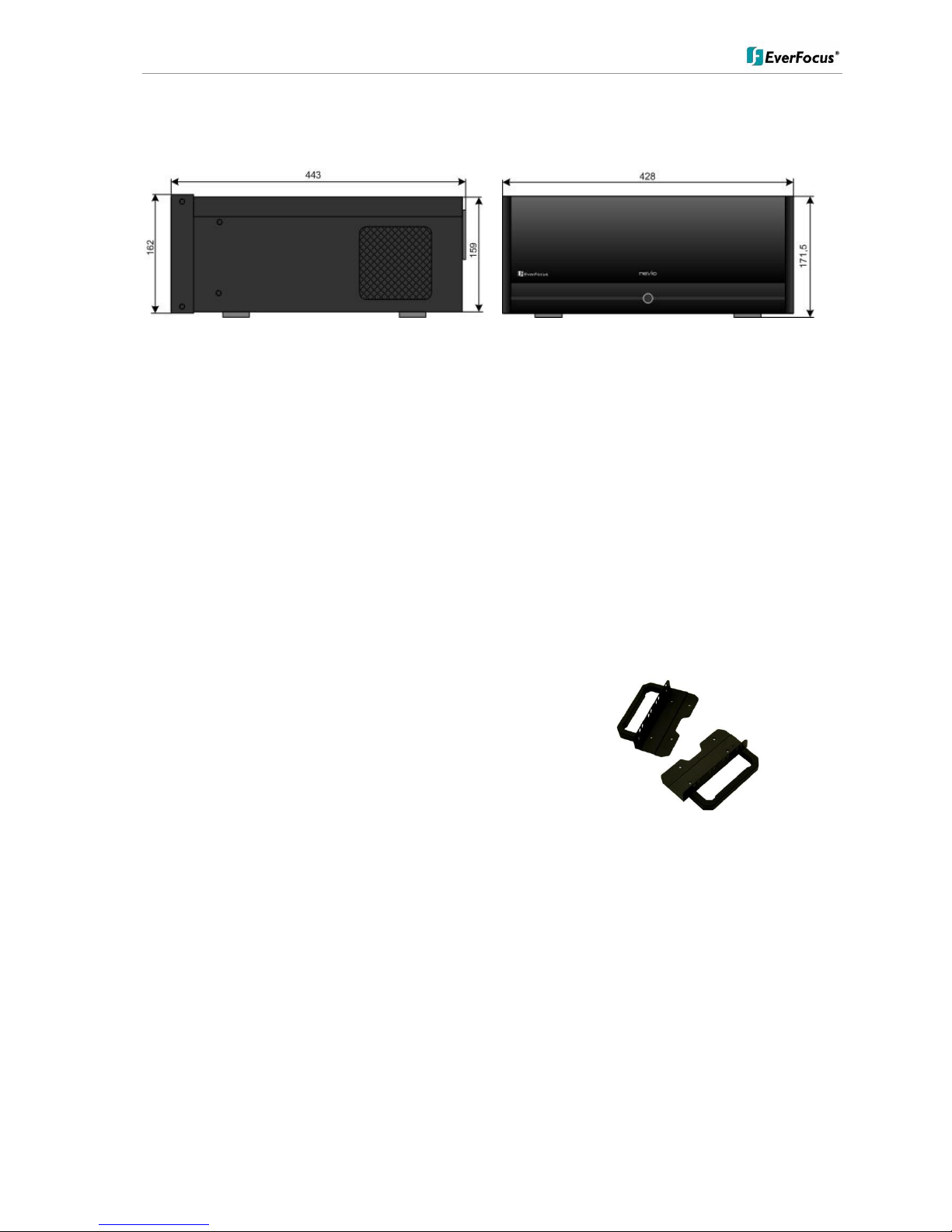
3.3 Dimensions
3.4 Delivery scope
ENRxxx depending on ordered version
PC keyboard
PC mouse
DVI-VGA adaptor
CD-ROM with recovery software, remote software and documentation (software includes: Remote
Live Client, Remote Playback Client, Database Maintenance Tool, Backup Software)
User manual
3.5 Optional Accessories
BA RK01 – 19” rack mounting brackets
Material: aluminium handle, steel mounting plate
Dimensions handle (LxD): 115 x 40 mm
Dimensions (WxLxD): 24 x 135 x 95 mm
Colour: black
Weight: 200 g
Note: The brackets are for fixation in 19" rack only. Due to the weight of the ENR device, additional support
brackets for the 19" rack are required!
ENR 400 Installation Manual
9 of 81 ENR400_ma_inst_en_rev01
4 Hardware installation
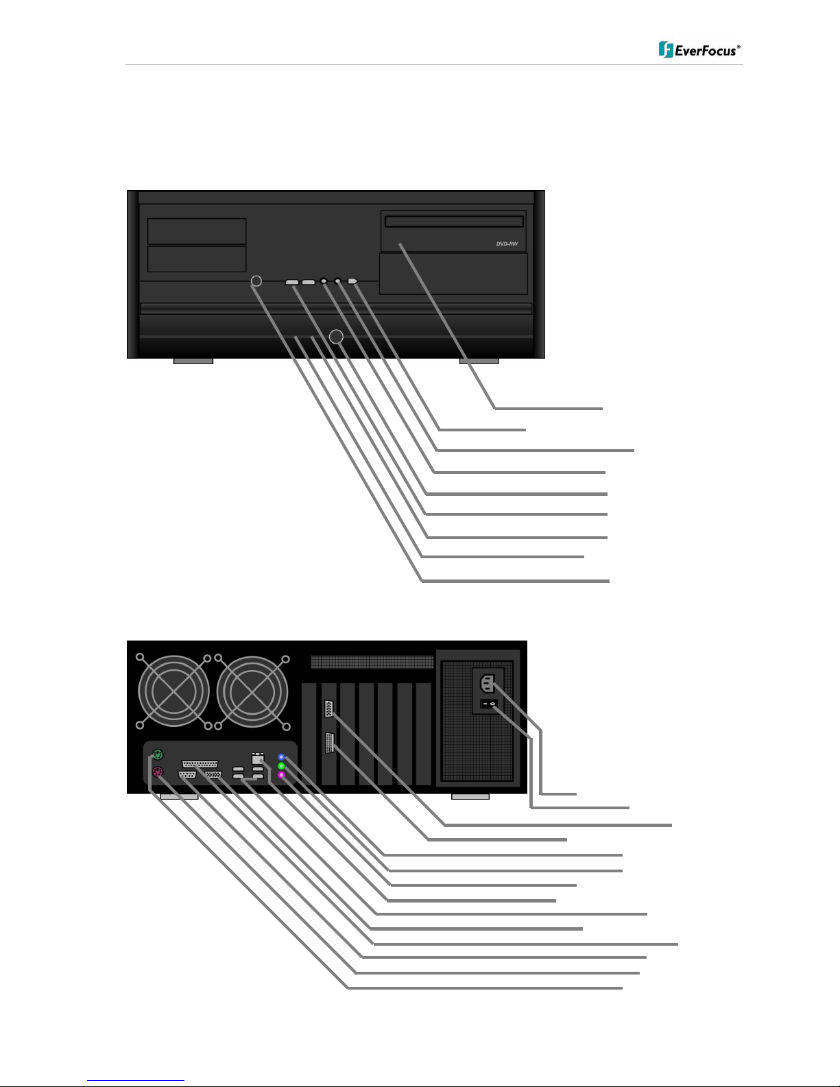
4.1 Front panel controls and connectors
4.2 Back panel connectors
DVD-RW drive
Firewire-connector (reserved)
Audio out
Microphone in
Power switch
2 x USB 2.0
Power LED
HDD Access LED
Reset switch
Power in socket 110/230 VAC
Mains Power switch
VGA - Output
DVI / VGA (with adapter) Output
Audio line input (blue)
Audio output (green)
Audio microphone input (pink)
LAN (RJ45) port, Gigabit interface
USB 2.0 port 4 x
VGA out (reserved, not used)
Parallel port
Serial RS232 port
PS/2 mouse socket
PS/2 keyboard socket

ENR 400 Installation Manual
10 of 81 ENR400_ma_inst_en_rev01
4.3 Status LED Gigabit LAN port
The LAN RJ45 socked has 2 integrated LED for status of the LAN connectivity:
4.4 System connections
The ENR series is designed for network recording in Local Area Network (LAN).
NOTE: Recordings of cameras, which are connected with router/DSL lines via internet are not supported
For full performance it is recommended to install a separate network for the IP video security system.
Further on the LAN connection between network switch and EVR should support Gigabit network
transmission.
The following figure shows a typical installation:
ENR 400 Installation Manual
11 of 81 ENR400_ma_inst_en_rev01
5 System Setup
5.1 First Time System Start
With factory default user settings the ENR will boot automatically and starts the ENR software application without
requiring Windows Login and Application login.
Switch on the backside power switch and push the front power switch to start the ENR.
The ENR application starts with administrator user right level.
With this setting the ENR will also recover record mode in case of restart after power loss.
For setup of user accounts incl. passwords please refer to chapter "User Account Settings".
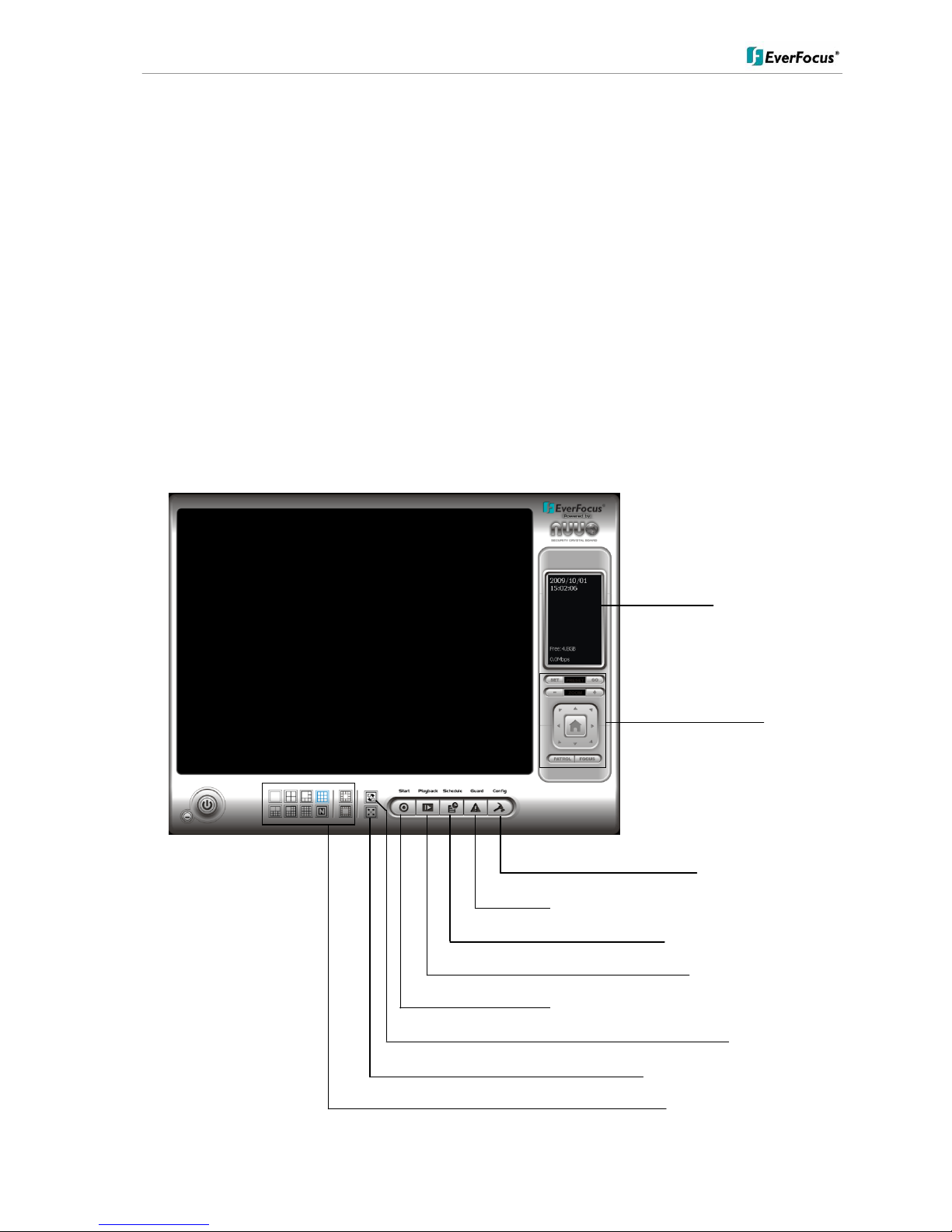
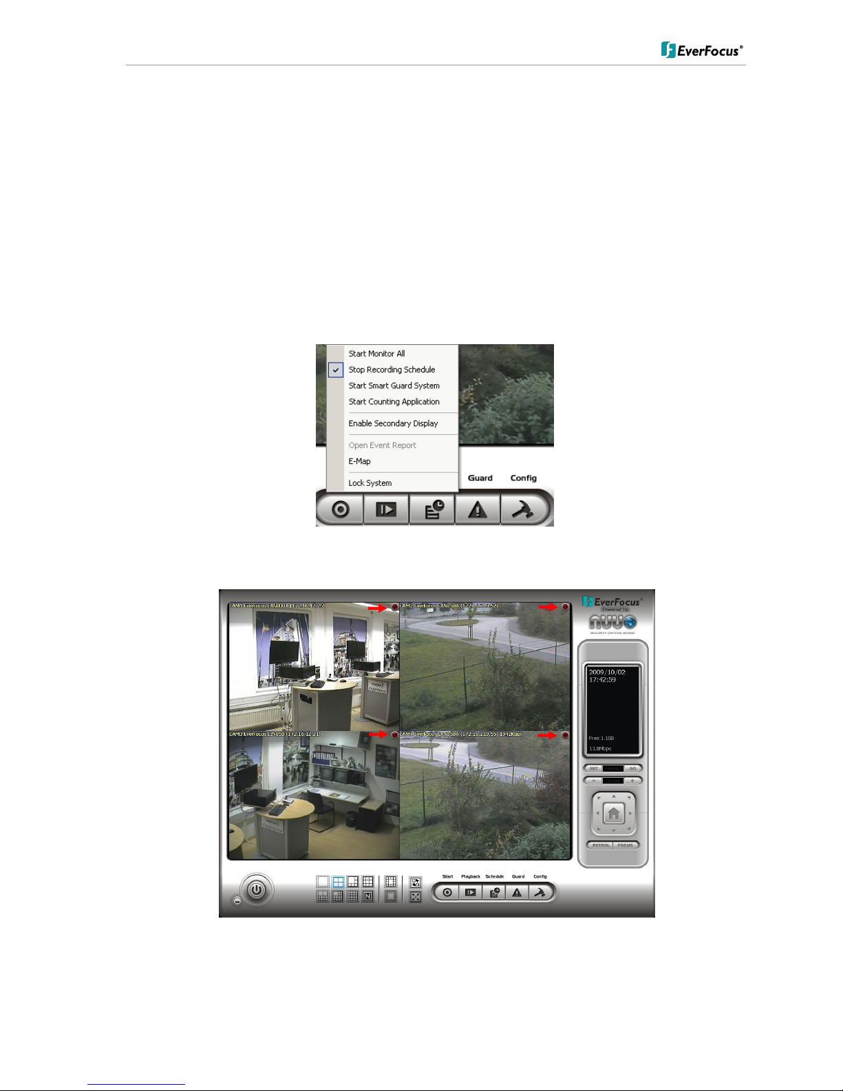
5.2 Main Console screen controls
After start-up the main screen will appear:
Status display area
PTZ control
System configuration
"Guard" mode setup (live monitoring events)
Scheduled recording setup
Start Playback window
Start: Start / disable application components
Sequence mode
Fullscreen display (frameless)
Multiscreen display modes
ENR 400 Installation Manual
12 of 81 ENR400_ma_inst_en_rev01
5.3 Quick Start Setup
This chapter describes the minimum installation steps to install IP-cameras for standard (continuous) recording.
Note: Precondition for this quick start setup is that all IP cameras of the system are installed in the same network
and IP address range as the ENR. The default IP setting of the ENR is DHCP mode with alternative IP
setting (if the network doesn’t support DHCP):
IP: 192.168.1.100
Subnet mask: 255.255.0.0
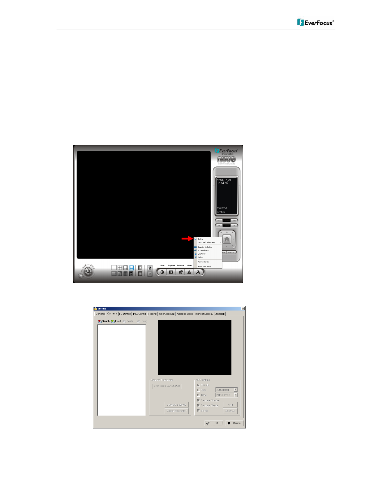
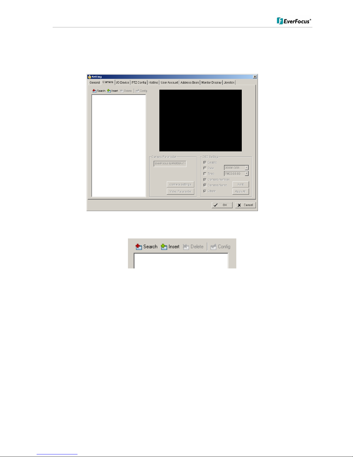
1. Open camera setup menu >CONFIG > SETTING > tab CAMERA:
After selecting the tab CAMERA, the screen shows the camera setup with an empty camera list.
The camera setup supports 2 methods to install cameras:
ENR 400 Installation Manual
13 of 81 ENR400_ma_inst_en_rev01
+Search: Express setup for camera types supporting UPnP. (EverFocus Nevio IP camera series support UPnP).
+Insert: Manual input of camera data for camera types, not supporting UPnP.
Camera setup with SEARCH function
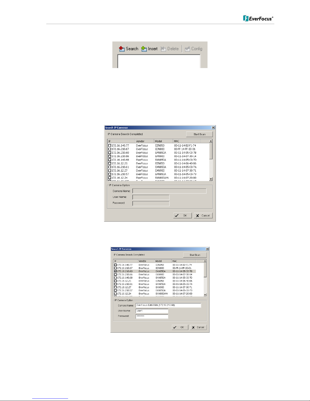
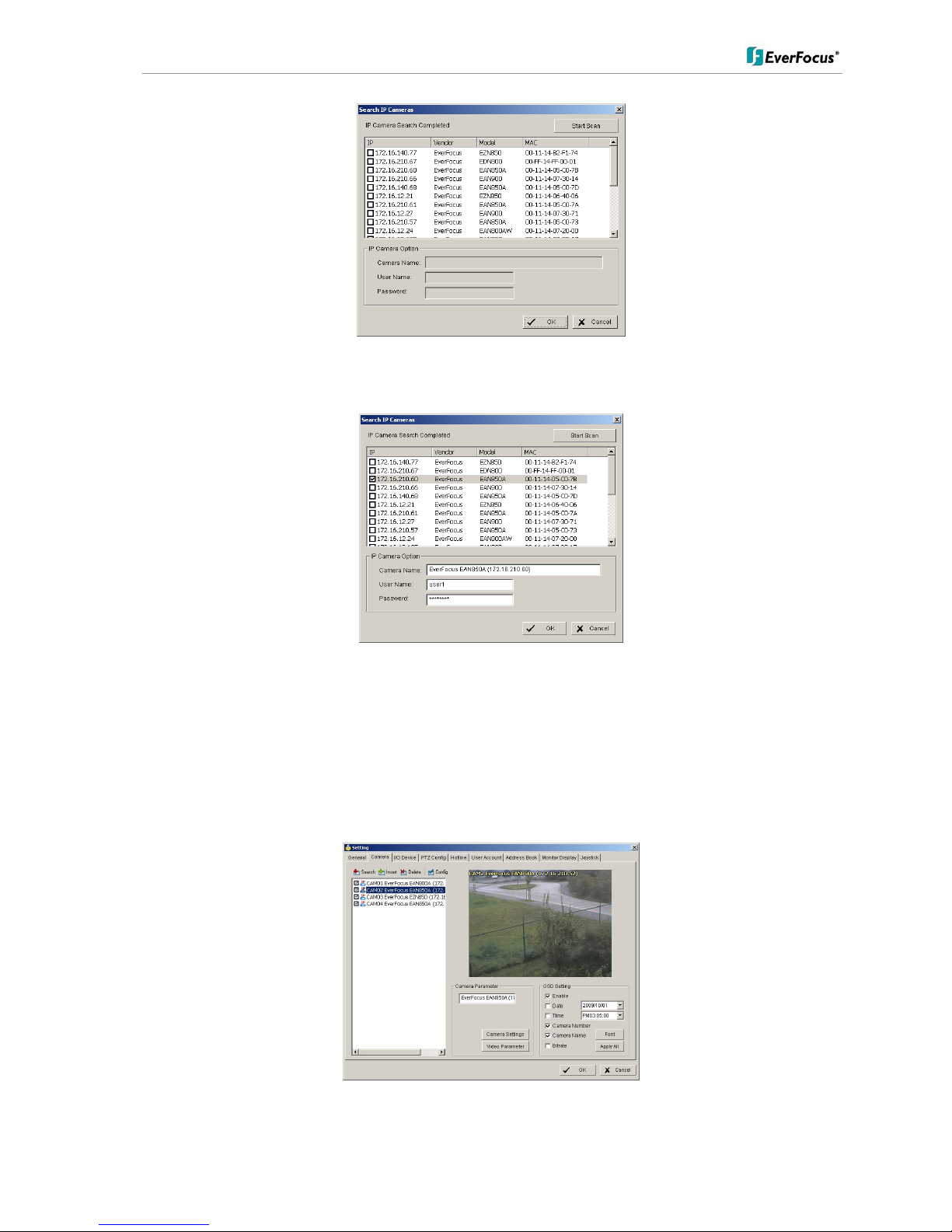
Click on +SEARCH to install cameras with UPnP support, a list with all available cameras appears:
Select a camera for installing and activate the checkbox at left side:
Enter user name and password for this camera and if applicable the camera name.
Default user name and password for EverFocus NEVIO cameras is:
User name (admin level): user1
Password: 11111111
ENR 400 Installation Manual
14 of 81 ENR400_ma_inst_en_rev01
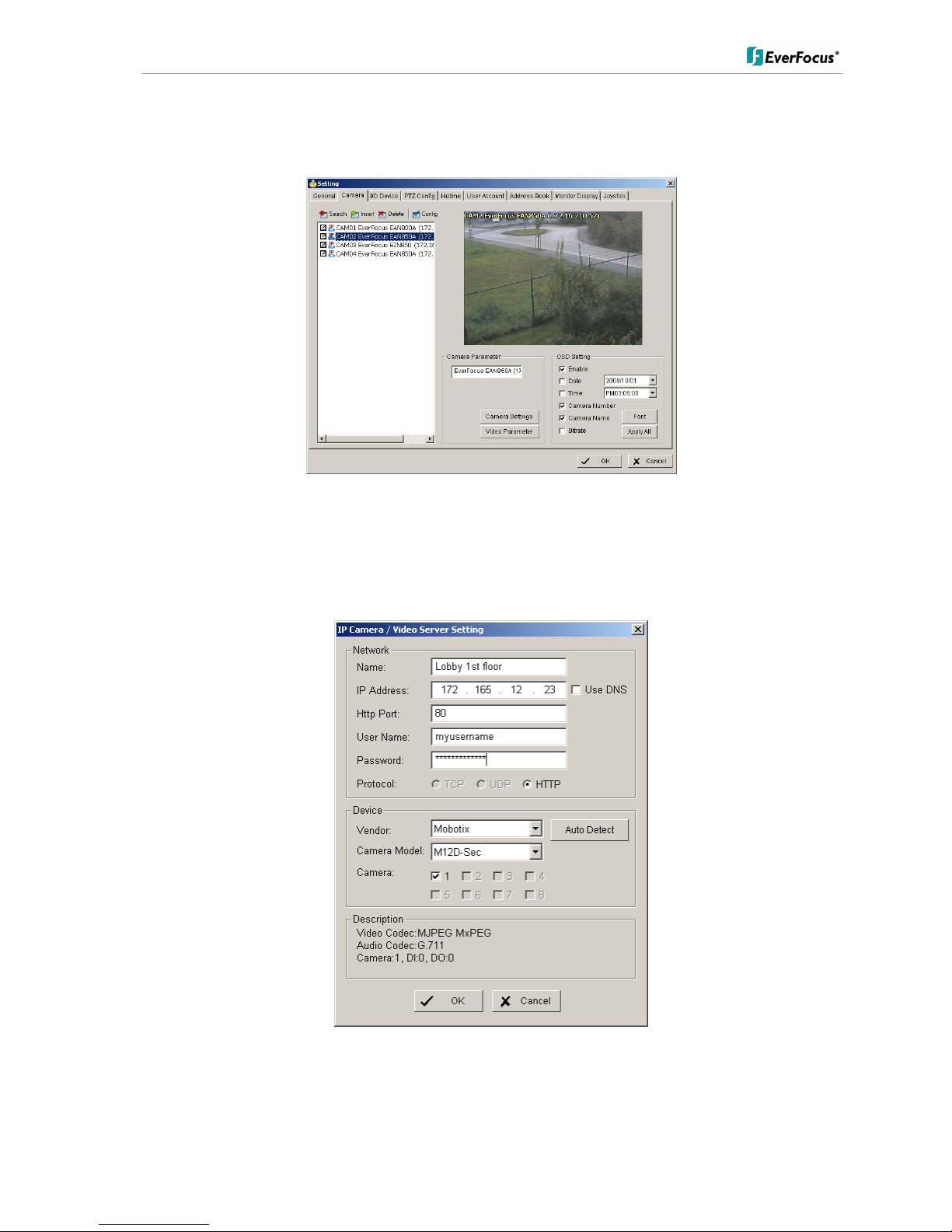
After setting the desired cameras confirm with OK to take over these cameras in the ENR camera list:
Manual IP camera setup
Alternative to the search function it is possible to setup cameras including IP settings manually. Click the button
+INSERT to open the setup window:
Enter IP parameter and user name / password.
Under DEVICE select a listed vendor and camera model or use the AUTO DETECT function.
Click OK to take over the settings.
ENR 400 Installation Manual
15 of 81 ENR400_ma_inst_en_rev01
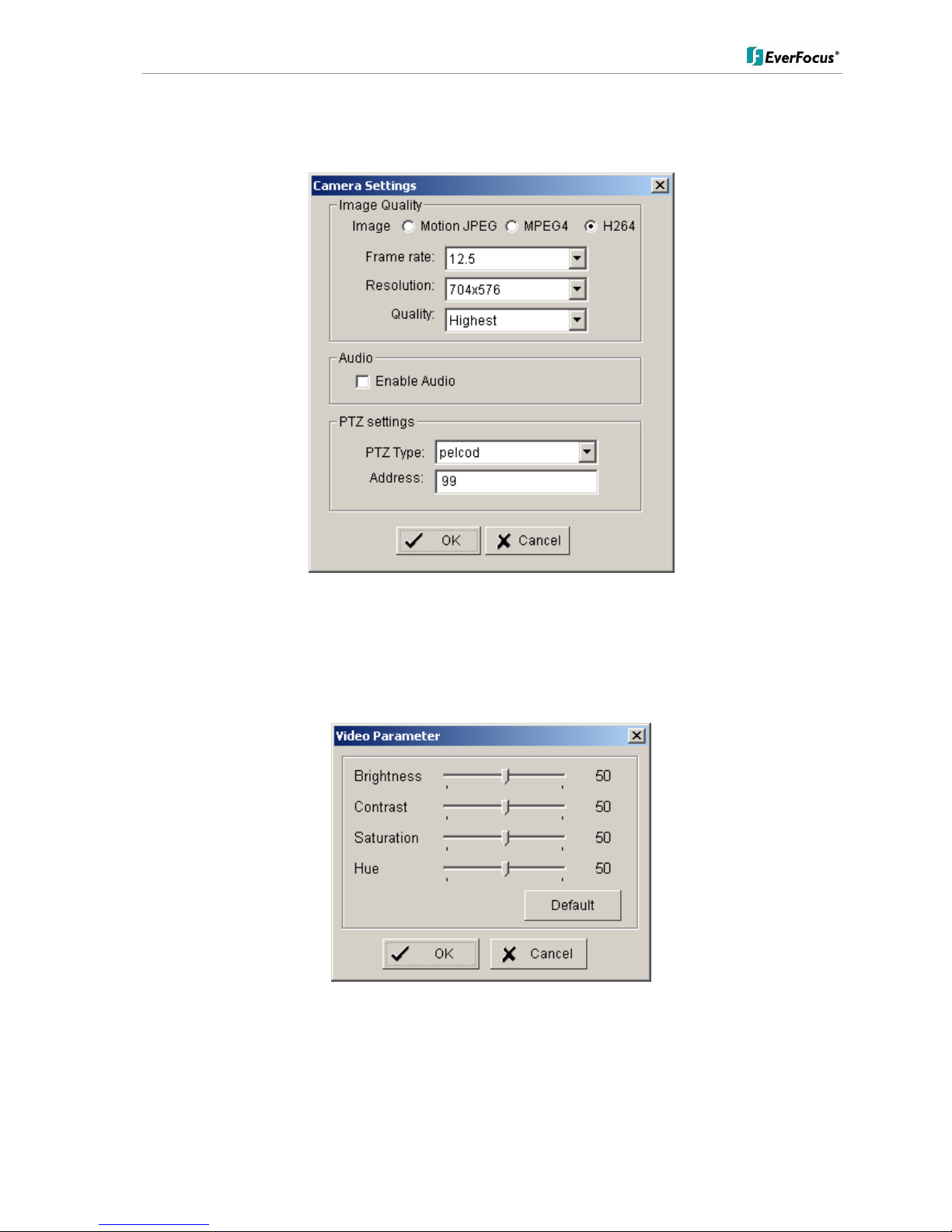
For changing frame rate and recording image quality select a camera from the list and press CAMERA
SETTINGS button:
The window shows current camera settings. Possible values depend on camera type.
Change the setting to the recording system requirements and confirm with OK.
Optional it is possible to adjust camera display setting, click on VIDEO PARAMETER:
After adjusting the display parameters confirm with OK.
ENR 400 Installation Manual
16 of 81 ENR400_ma_inst_en_rev01
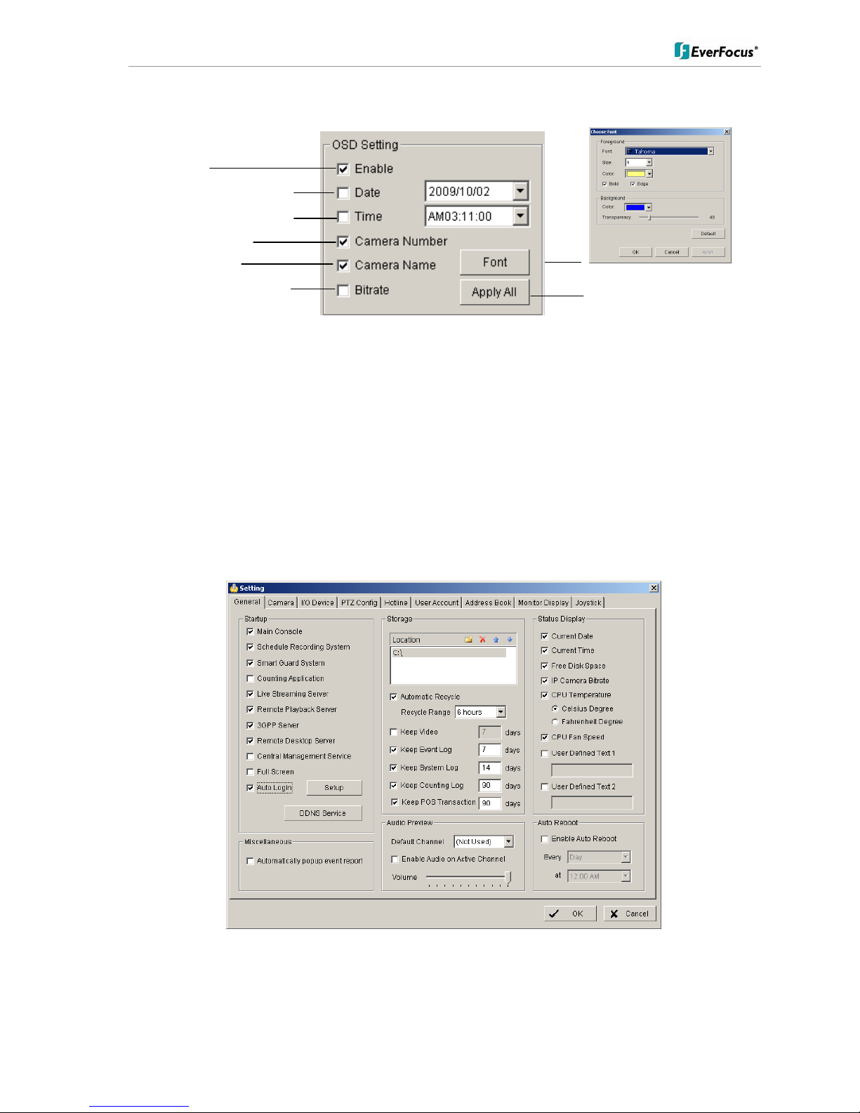
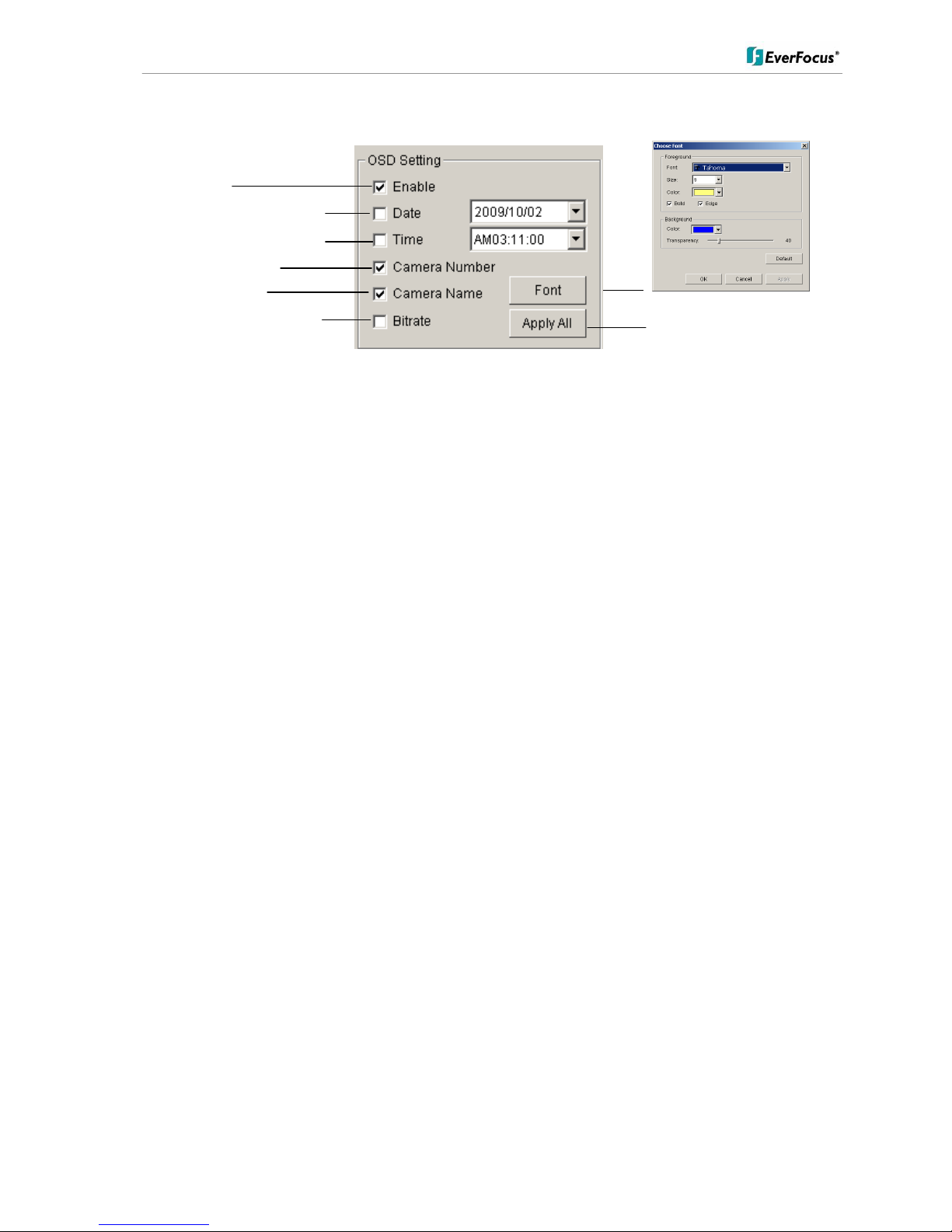
On lower right side of camera setup screen are additional settings for On Screen Display overlay display:
If all settings are done, confirm with OK in CAMERA setup menu.
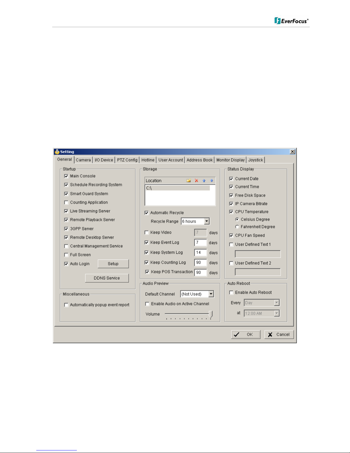
Minimum settings in GENERAL menu.
Open camera setup menu >CONFIG > SETTING > tab GENERAL:
1. Please double-check, that all recording HDD are entered correctly under LOCATION.
These drives are entered already by factory depending on order (1 to 4 HDD).
2. Check and adjust the other important recording settings:
Automatic Recycle: with activated checkbox the ENR will delete oldest records, if the recording HDD are filled.
Recycle Range: interval (1h to 1 day), how often ENR checks for deleting old records
Keep Video: If activated, the ENR will delete video data after a defined time period. If not activated, the ENR will
use full HDD capacity for achieving max. recording time.
OSD on/off
OSD of date / date adjustment
OSD of time / time adjustment
OSD camera number
OSD camera name
OSD bitrate of single camera
OSD font settings
Apply selection to all listed cameras
ENR 400 Installation Manual
17 of 81 ENR400_ma_inst_en_rev01
If recording shall start automatically after application start, activate the checkbox SCHEDULE RECORDING
SYSTEM under START-UP.
Confirm all settings with OK.
With these basic settings the ENR is configured already for continuous recording.
For more detailed settings including schedule and event management refer to the following chapters DETAILED
SETUP.
Finally check under > Start, that RECORDING SCHEDULE is activated.
The system will record now, recording is indicated by a red point in each recording video channel.
ENR 400 Installation Manual
18 of 81 ENR400_ma_inst_en_rev01
5.4 Detailed Setup
Following chapters describe the setup options of the ENR in all details.
5.4.1 Setting - General
open with > CONFIG > SETTING
This menu defines general parameters, display and start-up behaviour of the ENR.
Start-up - Behaviour of ENR after booting
Main Console:
with activated checkbox the ENR application starts automatically after
Windows start
Smart Guard System:
with activated checkbox the life event management will be activated at ENR
start
Counting application:
with activated checkbox the counting application will be activated at ENR start

ENR 400 Installation Manual
19 of 81 ENR400_ma_inst_en_rev01
Live streaming server:
with activated checkbox the steaming server for live view will be activated at
ENR start
Remote playback server:
with activated checkbox the steaming server for playback view will be activated
at ENR start
3GGP server:
with activated checkbox the 3GGP mobile phone server will be activated at
ENR start
Remote desktop server:
with activated checkbox the remote desktop server will be activated at ENR
start
Central management service:
reserved
Full screen:
with activated checkbox the ENR application will start in full screen mode
Auto login:
with activated checkbox the ENR application requires no manual login.
Storage - Settings for storage location and general recording parameters
Location
List of recording HDD and recording path. Please check, if all drives are listed.
Automatic Recycle
with activated checkbox the ENR will delete oldest records, if the recording
HDD are filled.
Recycle range
interval (1h to 1 day), how often ENR checks for deleting old records
Keep video
If activated, the ENR will delete video data after a defined time period. If not
activated, the ENR will use full HDD capacity for achieving max. recording
time.
Keep event log
If activated, the ENR will delete event log data older than the entered value in
days
Keep system log
If activated, the ENR will delete system log data older than the entered value in
days
Keep counting log
If activated, the ENR will delete counting log data older than the entered value
in days
Keep POS transaction
reserved
Audio Preview - Live monitoring audio settings
Default channel
Select the audio channel, which is active in any multi-view without selecting a
camera in this view
Enable Audio on Active
Channel
If activated, Audio output will change to selected camera channel
Volume
Audio output volume
ENR 400 Installation Manual
20 of 81 ENR400_ma_inst_en_rev01
Status Display - Display options for global status display (right side of main screen)
Display options, displayed with activated checkbox
Current time
Current date
Free disk space (total for all recording drives)
IP camera bitrate (summarised input stream)
CPU Temperature (not supported)
CPU fan speed (not supported)
User defined text 1 (free editable)
User defined text 2 (free editable)
Auto reboot
With activated checkbox the system will reboot in defined time interval.
If you use this function, make sure to activate under START-UP:
Main console
Schedule recording system
Auto login
Otherwise the recording function will not recover automatically after reboot.
5.4.2 Setting - Camera
1. Open camera setup menu >CONFIG > SETTING > tab CAMERA:
ENR 400 Installation Manual
21 of 81 ENR400_ma_inst_en_rev01
After selecting the tab CAMERA the screen shows camera setup with an empty camera list.
The camera setup supports 2 methods to install cameras:
+Search: Express setup for camera types, which support UPnP. (EverFocus Nevio IP camera series support
UPnP).
+Insert: Manual input of camera data for camera types, which have no UPnP support.
Camera setup with SEARCH function
Click on +SEARCH to install cameras with UPnP support, a list with all available cameras appears:
ENR 400 Installation Manual
22 of 81 ENR400_ma_inst_en_rev01
Select a camera for installing and activate the checkbox at left side:
Enter user name and password for this camera and if applicable the camera name.
Default user name and password for EverFocus NEVIO cameras is:
user name (admin level): user1
password: 11111111
After setting the desired cameras confirm with OK to take over these cameras in the ENR camera list:

ENR 400 Installation Manual
23 of 81 ENR400_ma_inst_en_rev01
Manual IP camera setup
Alternative to the search function it is possible to setup cameras including IP settings manually. Click the button
+INSERT to open the setup window:
Enter IP parameter and user name / password.
Under DEVICE select a listed vendor and camera model or use the AUTO DETECT function.
Click OK to take over the settings.

ENR 400 Installation Manual
24 of 81 ENR400_ma_inst_en_rev01
For changing frame rate and recording image quality select a camera from the list and press CAMERA
SETTINGS button:
The window shows current camera settings. Possible values depend on camera type.
Change the setting to the recording system requirements and confirm with OK.
Optional it is possible to adjust camera display setting, click on VIDEO PARAMETER:
After adjusting the display parameters confirm with OK.
ENR 400 Installation Manual
25 of 81 ENR400_ma_inst_en_rev01
On lower right side of camera setup screen are additional settings for On Screen Display overlay display:
If all settings are done, confirm with OK in CAMERA setup menu.
OSD on/off
OSD of date / date adjustment
OSD of time / time adjustment
OSD camera number
OSD camera name
OSD bitrate of single camera
OSD font settings
Apply selection to all listed cameras
 Loading...