

EverFocus ENDEAVOR EDRHD-2H14, ENDEAVOR EDRHD-4H14 User Manual
User Manual
E
E
N
N
E
((E
D
D
D
D
E
E
R
R
AVV
A
H
H
O
R SS
O
R
D--22
D
D++
D
H1144 // 44
H
H
H
D
D
DVV
D
H44))
H
R
R

EVERFOCUS ELECTRONICS CORPORATION
ENDEA VOR SD+HD D VR
Instruction Manual
2010 EverFocus Electronics Corp
www.everfocus.com
All rights reserved. No part of the contents of this manual may be reproduced or transmitted in any form or by
any means without written permission of the Everfocus Electronics Corporation.
Release Date: Feb. 2011
QuickTime is a registered trademark of the Apple Computer, Inc.
Windows is a registered trademark of the Microsoft Corporation.
Linksys is a registered trademark of the Linksys Corporation.
D-Link is a registered trademark of the D-Link Corporation.
DynDNS is a registered trademark of the DynDNS.org Corporation.
Other product and company names mentioned herein may be the trademarks of their respective owners.

Safety Precautions
Refer all work related to the installation of this product to qualified service personnel or system
installers.
Do not block the ventilation openings or slots on the cover.
Do not drop metallic parts through slots. This could permanently damage the appliance. Turn the
power off immediately and contact qualified service personnel for service.
Do not attempt to disassemble the appliance. To prevent electric shock, do not remove screws or
covers. There are no user-serviceable parts inside. Contact qualified service personnel for
maintenance. Handle the appliance with care. Do not strike or shake, as this may damage the
appliance.
Do not expose the appliance to water or moisture, nor try to operate it in wet areas. Do take immediate
action if the appliance becomes wet. Turn the power off and refer servicing to qualified service
personnel. Moisture may damage the appliance and also may cause electric shock.
Do not use strong or abrasive detergents when cleaning the appliance body. Use a dry cloth to clean
the appliance when it is dirty. When the dirt is hard to remove, use a mild detergent and wipe gently.
Do not overload outlets and extension cords as this may result in a risk of fire or electric shock.
Do not operate the appliance beyond its specified temperature, humidity or power source ratings. Do
not use the appliance in an extreme environment where high temperature or high humidity exists. Use
the DVR at indoor type temperatures within 0°C~40°C (32°F~104°F) and at relative humidity between
20%~80%. The input power source for this device is 12VDC though a power supply which operates
from100~240VAC.
Read Instructions
All the safety and operating instructions should be read before the unit is operated.
Retain Instructions
The safety and operating instructions should be retained for future reference.
Heed Warnings
All warnings on the unit and in the operating instructions should be adhered to.
Follow Instructions
All operating and use instructions should be followed.
Cleaning
ii

Unplug the unit from the outlet before cleaning. Do not use liquid cleaners, abrasive or aerosol
cleaners. Use a damp cloth for cleaning
Attachments
Do not use attachments not recommended by the product manufacturer as they may cause hazards.
Water and Moisture
Do not use this unit near water-for example, near a bath tub, wash bowl, kitchen sink, or laundry tub,
in a wet basement, near a swimming pool, in an unprotected outdoor installation, or any area which is
classified as a wet location.
Servicing
Do not attempt to service this unit by yourself as opening or removing covers may expose you to
dangerous voltage or other hazards. Refer all servicing to qualified service personnel.
Power Cord Protection
Power supply cords should be routed so that they are not likely to be walked on or pinched by items
placed upon or against them, playing particular attention to cords and plugs, convenience receptacles,
and the point where they exit from the appliance.
Object and Liquid Entry
Never push objects of any kind into this unit through openings as they may touch dangerous voltage
points or short-out parts that could result in a fire or electric shock. Never spill liquid of any kind on the
unit.
"Rack Mount Instructions - The following or similar rack-mount instructions are included with the installation
instructions:
A) Elevated Operating Ambient - If installed in a closed or multi-unit rack assembly, the operating ambient
temperature of the rack environment may be greater than room ambient. Therefore, consideration should
be given to installing the equipment in an environment compatible with the maximum ambient temperature
(Tma) specified by the manufacturer.
B) Reduced Air Flow - Installation of the equipment in a rack should be such that the amount of air flow
required for safe operation of the equipment is not compromised.
C) Mechanical Loading - Mounting of the equipment in the rack should be such that a hazardous condition
is not achieved due to uneven mechanical loading.
D) Circuit Overloading - Consideration should be given to the connection of the equipment to the supply
circuit and the effect that overloading of the circuits might have on overcurrent protection and supply wiring.
Appropriate consideration of equipment nameplate ratings should be used when addressing this concern.
iii
y
E) Reliable Earthing - Reliable earthing of rack-mounted equipment should be maintained. Particular
attention should be given to supply connections other than direct connections to the branch circuit (e.g. use
of power strips)."
ATTENTION! This is a class A product which may cause radio interference in a domestic environment; in
this case, the user ma
be urged to take adequate measures.
Federal Communication Commission Interference Statement
This equipment has been tested and found to comply with the limits for a Class B digital device, pursuant to
Part 15 of the FCC Rules. These limits are designed to provide reasonable protection against harmful
interference in a residential installation. This equipment generates, uses and can radiate radio frequency
energy and, if not installed and used in accordance with the instructions, may cause harmful interference to
radio communications. However, there is no guarantee that interference will not occur in a particular
installation. If this equipment does cause harmful interference to radio or television reception, which can be
determined by turning the equipment off and on, the user is encouraged to try to correct the interference by
one of the following measures :
•Reorient or relocate the receiving antenna.
•Increase the separation between the equipment and receiver.
•Connect the equipment into an outlet on a circuit different from that to which the receiver is connected.
•Consult the dealer or an experienced radio/TV technician for help.
FCC Caution: Any changes or modifications not expressly approved by the party responsible for compliance
could void the users’ authority to operate this equipment.
WEEE
This Product is RoHS compliant.
The information in this manual was current upon publication. The manufacturer reserves the right to revise and improve his products.
Therefore, all specifications are subject to change without prior notice. Manufacturer is not responsible for misprints or typographical
errors.
Please read this manual carefully before installing and using this unit. Be sure to keep it handy for later reference.
iv

TABLE OF CONTENTS
1 PRODUCT OVERVIEW..................................................................................................... 1
1.1 FEATURES....................................................................................................................... 1
1.2 PACKAGE CONTENTS................................................................................................... 3
1.3 SPECIFICATIONS ........................................................................................................... 4
1.4 FRONT
1.5 REAR
2 INSTALLATION................................................................................................................ 11
2.1 HD-CCTV WIRING FOR VIDEO INPUTS ............................................................................. 11
2.1.1 Understanding HD-CCTV signals and wiring ......................................................................................11
2.1.2 HD-CCTV signal...................................................................................................................................11
2.1.3 Cable types............................................................................................................................................12
2.1.4 Cable installation..................................................................................................................................13
2.1.5 BNC-plug...............................................................................................................................................13
2.1.6 Extended cable lengths with repeater EHA-RPT / converter EHA-SRX ...............................................13
2.1.7 Extended cable lengths with fiber optics transmission..........................................................................14
2.1.8 MONITOR INSTALLATION..................................................................................................................15
2.2 AUDIO INSTALLATION .............................................................................................. 15
2.3 ALARM CONTACTS INSTALLATION....................................................................... 16
2.3.1 Alarm Input Contacts............................................................................................................................16
2.3.2 Alarm Output Relay...............................................................................................................................16
2.4 RS-485 KEYBOARD / PTZ INSTALLATION......................................................................... 16
2.4.1 General RS-485 bus installation ...........................................................................................................17
2.4.2 RS-485 ports..........................................................................................................................................18
2.4.3 EKB-500 connection with network patch cable.....................................................................................18
2.4.4 EKB-500 connection to several DVRs...................................................................................................18
2.4.5 Speed Dome Installation .......................................................................................................................18
2.5 USB-M
2.6 NETWORK
2.6.1 Direct PC Connection through Crossover Network Cable ...................................................................19
2.6.2 Network Connection through Patch Cable............................................................................................20
2.7 FINAL
PANEL ................................................................................................................ 6
PANEL................................................................................................................... 9
OUSE INSTALLATION ............................................................................................ 19
CONNECTION .......................................................................................... 19
INSTALL PROCESS.......................................................................................... 21
3 MOUSE AND FRONT PANEL OPERATION ............................................................... 22
3.1 GENERAL USB MOUSE OPERATION....................................................................... 22
3.1.1 How to select a channel / Enable audio................................................................................................22
3.1.2 OSD Root Menu.....................................................................................................................................22
3.1.3 Operation in the Configuration Menus.................................................................................................23
3.1.4 Field Input Options ...............................................................................................................................23
2.2 G
2.2.1 How to select a channel / Enable audio.......................................................................................................25
2.2.2 OSD Root Menu ...........................................................................................................................................25
2.2.3 Front Panel Key Review...............................................................................................................................25
ENERAL FRONT PANEL OPERATION ............................................................................... 25
v

2.2.4 Operation in Configuration Menu.........................................................................................................25
2.2.5 Field Input Options ...............................................................................................................................26
3. GENERAL DVR OPERATIONS...................................................................................... 28
3.1 RECORD......................................................................................................................... 28
3.2 LOGIN............................................................................................................................. 28
3.3 SELECT CAMERA OPERATION................................................................................. 29
3.5 PLAYBACK.................................................................................................................... 30
3.6 PTZ.................................................................................................................................. 31
3.6.1 General PTZ control (if PTZ cameras are installed)..................................................................................31
3.6.2 Express Control of PTZ.........................................................................................................................32
3.7 LAYOUT......................................................................................................................... 34
3.7.1 Bring a camera to full screen mode.......................................................................................................34
3.8 CHANNEL
SWITCHING............................................................................................... 34
3.9 DISPLAY ........................................................................................................................ 35
3.10 SEQUENCE.................................................................................................................. 35
3.11 ZOOM........................................................................................................................... 35
3.12 SEARCH....................................................................................................................... 36
3.12.1 Time Search...........................................................................................................................................37
3.12.2 Event Search..........................................................................................................................................37
3.12.3 Smart Search .........................................................................................................................................38
3.12.4 Snapshot Search ....................................................................................................................................41
3.13 COPY............................................................................................................................ 43
3.14 LOGOUT...................................................................................................................... 44
4 DVR CONFIGURATION.................................................................................................. 45
4.1 CONFIGURATION MENU............................................................................................ 45
4.2 EXPRESS........................................................................................................................ 45
4.3 CAMERA SETTING ...................................................................................................... 48
4.3.1 Basic Setting..........................................................................................................................................48
4.3.2 Video Adjust (apply to analog camera only).........................................................................................50
4.3.3 Motion ...................................................................................................................................................51
4.3.4 Video Loss.............................................................................................................................................54
4.4 RECORD & PLAY SETTING........................................................................................ 56
4.4.1 Record...................................................................................................................................................56
4.4.2 Built-in Calculator ................................................................................................................................57
4.4.3 Play .......................................................................................................................................................58
4.5 ALARM & EVENT SETTING....................................................................................... 59
4.5.1 Alarm .....................................................................................................................................................59
4.5.2 Event......................................................................................................................................................61
4.6 SCHEDULE SETTING................................................................................................... 69
4.6.1 Express Setup .......................................................................................................................................69
4.6.2 Holidays ................................................................................................................................................70
4.6.3 Schedule ................................................................................................................................................71
4.6.4 Alarm Action .........................................................................................................................................76
4.7 NETWORK SETTING.................................................................................................... 80
4.7.1 LAN .......................................................................................................................................................80
4.7.2 EMAIL...................................................................................................................................................82
vi

4.7.3 DDNS ....................................................................................................................................................83
4.7.4 Alarm Server .........................................................................................................................................85
4.7.5 Network Test..........................................................................................................................................86
4.8 DISK
4.8.1 Disk .......................................................................................................................................................87
4.8.2 Lock/Format..........................................................................................................................................88
INFORMATION................................................................................................... 87
4.9 DISPLAY SETTING....................................................................................................... 89
4.9.1 Monitor OSD.........................................................................................................................................89
4.9.2 Main M/T SEQ ......................................................................................................................................90
4.10 SYSTEM SETTING..................................................................................................... 91
4.10.1 Date/Time..............................................................................................................................................91
4.10.2 Daylight Saving.....................................................................................................................................92
4.10.3 User.......................................................................................................................................................93
4.10.4 I/O Control ............................................................................................................................................96
4.10.5 Misc. ......................................................................................................................................................97
4.11 INFORMATION........................................................................................................... 99
4.11.1 System....................................................................................................................................................99
4.11.2 Log.......................................................................................................................................................100
5 NETWORKING OVERVIEW........................................................................................ 102
5.1 INTRODUCTION TO TCP/IP............................................................................................. 102
5.2 SUBNET MASKS.............................................................................................................. 102
5.3 GATEWAY ADDRESS....................................................................................................... 102
5.4 VIRTUAL PORTS.............................................................................................................. 103
5.5 PRE-INSTALLATION ........................................................................................................ 103
5.6 WHAT IS YOUR NETWORK SETUP?.................................................................................. 104
5.7 SIMPLE ONE TO ONE CONNECTION................................................................................. 105
5.8 DIRECT HIGH SPEED MODEM CONNECTION ................................................................... 110
5.9 ROUTER OR LAN CONNECTION...................................................................................... 112
6 REMOTE OPERATION FROM BROWSER.................................................................... 115
6.1 CONNECTING TO ENDEAVOR SD+HD ...................................................................... 115
6.2 BROWSER SECURITY SETTING .................................................................................. 116
6.2.1 Installing ActiveX controls..................................................................................................................116
Enabling ActiveX Controls..................................................................................................................................119
6.3 REMOTE LIVE VIEW................................................................................................. 122
6.4 REMOTE PLAYBACK................................................................................................ 124
7 EVERFOCUS DDNS SETUP.......................................................................................... 125
8 LINKSYS & D-LINK PORT FORWARDING ............................................................. 127
8.2 TYPICAL LINKSYS PORT FORWARDING
8.3 TYPICAL
D-LINK PORT FORWARDING ................................................................ 129
............................................................. 127
9 TROUBLESHOOTING
APPENDIX A: TIMING OF ALARM MODES.................................................................... 134
APPENDIX B: EXPRESS SETUP RECORDING VALUE SELECTION RULES .......... 137
................................................................................................... 132
vii

APPENDIX C: REMOTE CONTROL................................................................................... 139
viii

Chapter
1
1 PRODUCT O VERVIEW
Begin your migration to the High Definition revolution in CCTV technology without changing your
installation methods. For definitive identification in critical areas, capture scenes with stunning HD
clarity; for traditional applications connect standard definition analog CCTV cameras. Carry uncompressed
full motion MEGAPIXEL DIGITAL and analog NTSC video back to their respective inputs on the
ENDEAVOR HD+SD DVR over standard coaxial cable*! Attach familiar BNC connectors to both HD-CCTV
and analog cameras and to the ENDEAVOR HD+SD DVR, then display live and recorded images in
astounding detail on the HDMI main monitor screen. HD-CCTV with up to 6 times the resolution of the
analog cameras delivers the ability to zoom with clarity. HD images are so detailed, each sends a 1.5Gb/s
uncompressed digital video signal over the coax; the Endeavor HD – 2H14 DVR can process that total of
3Gb/s from 2 HD-CCTV cameras, as well as the video from 14 analog cameras, for live viewing and H.264
recording at HD resolutions of 1080p (~2 megapixel @ 15 fps/camera) or 720p (~1 megapixel @ real time
30fps/camera), plus real time 30FPS at D1 recording capability on all 14 analog cameras. Dedicated
mega-bandwidth coax signal paths from each HD camera to this HD Hybrid DVR eliminate the need for
compression, addressing, and complex network design.
The ENDEAVOR HD+SD DVR is a powerful, full featured, embedded DVR with all the capabilities, familiar
front panel controls, user friendly mouse driven Graphical User Interface, plug-and play ease of installation
and setup and proven, reliable Linux based operating system that you expect from a state of the art
EverFocus DVR. More than that, it is designed and built in our factory, backed by our Support Team, and
carries our standard three year DVR warranty (including the hard drives). Start adding some High Definition
Security Surveillance to your systems at your own pace, with a name you know and trust: the ENDEAVOR
HD+SD DVR from Everfocus Electronics puts the future in your hands – TODAY!
*Up to 500’ nominal for digital signals on RG59; more with lower loss cable and/or optional repeaters.
1.1 FEA TU RES
o Both HD-CCTV Megapixel Video Inputs and Analog Video Inputs
o Choose 720p or 1080p HD resolution recording for HD-CCTV Video Inputs up to 30 FPS/camera
o H.264 Compression format to minimize optimize disk space consumption
o Dual streaming to optimize remote viewing bandwidth utilization
o Real time recording rate and playback rate – up to 30fps@D1 on analog and 30fps@HD on HD-CCTV
o Recording resolution and rate can be set independently for each camera, and changed via user defined
schedule
o Multiple Main Monitors : HDMI 1080p / VGA (1920x1080) output for stunning image clarity
o Pentaplex Operation (Simultaneous live, recording, playback, archiving and remote viewing)
1

o User friendly GUI with graphical icons and visual indicators
o Free EverFocus DDNS Service static IP address is not required for reliable remote access
o Supports eSATA external HDD array (EDA450)
o Supports remote/mobile monitoring via PC browsers, SmartPhones and iPhone/Android apps
o Multiple Control Inputs: mouse/front panel/ IR remote control/EKB500 keyboard
o Express Setup: A unique menu option for quick & easy installation and setup
o Express Playback: Simply point, click and drag the playback bar to view desired recordings
o Express Archive: Archive video instantly (to USB) while playing back
o Express Search: Use the intuitive playback bar with simple drag & drop operations
o Smart Search: Review recorded video to identify motion in area(s) of interest
o Snapshot search: choose an interval and direction, view a series of snapshots to quickly isolate
incidents
o Remote configuration support from built-in web interface
o Gigabit Ethernet interface for remote network viewing and control
o Audio recording capabilities
o Up to 4 internal HDDs
o Built-in DVD burner
o 2 USB 2.0 ports for video archive and mouse usage
o Multi-language support
o Watermark capabilities to identify intentional modifications of recorded data
o Compatible with FREE EverFocus Central Management Software
o USB Mouse and IR remote control included
o 19” Rack mountable – rack ears included
2

1.2 PACKA GE CONTENTS
Standard Package
-Digital Video Recorder x1
-User Manual x 1
-Power Cord x1
-Mouse x 1
-19” Rack mounting adapters (pair) x 1
-Terminal Block x 5
-IR Remote Control x 1
-Battery x 2
-Audio-in connector (D-sub to RCA) x 1
-HDD Fixing Bracket x 4 set
-SATA cable x 4
-Screws x 16 for HDD
-Screws x 8 for HDD fixing bracket
3

1.3 SPECIFICA TIO NS
ENDEAVOR HD+SD DVR
EDR HD-2H14 EDR HD-4H4
HD-CCTV Camera Inputs 2 BNC SMPTE292m compliant 4 BNC SMPTE292m compliant
Analog Camera Inputs 14 BNC 4 BNC
Looping Analog Camera Outputs 14 BNC 4 BNC
Compression Format H.264
Dual Streaming Yes (Configurable)
HD Recording Rate/Resolution
Choose one resolution for both channels
Analog Recording Rate/Resolution
Resolution and rate can be set independently
per camera up to the total D1 recording
capacity
HD Playback Rate/Resolution
Analog Playback Rate/Resolution
Mobile View
Pentaplex Operation Simultaneous Live, Recording, Playback, Archive and Remote
Main Monitor Outputs
(simultaneous display)
Audio Inputs 16 Inputs (RCA, line level) 8 Inputs (RCA, line level)
Audio Outputs 2 Outputs (RCA, line level)
Recording Modes Manual, Schedule and Event
Playback Search Date/Time, Event, Tex, Smart, Snapshot
Alarm Inputs 16 8
Alarm Outputs 4 Alarm Outputs – Form “C” rated at 30VDC, 1A
Video Pause Yes
Video Loss Detection Yes
Motion Detection Yes
Event Log Yes
Watch Dog Timer Yes
Internal HDD Support 4 Internal HDD (up to 8Tb max at time of printing)
External HDD Support 1 eSATA
DVD Drive DVD RW Built In
User Interface Color GUI (Graphical User Interface)
OS Embedded Linux
Network/Protocol Gigabit Ethernet; TCP-IP / DHCP/ PPPoE / DDNS / UDP / SMTP /
Control PTZ via OSD Local and via web interface
1080p 30fps NTSC / 25ps PAL 60fps NTSC / 50ps PAL
720p 60fps NTSC / 50ps PAL 120fps NTSC / 100ps PAL
D1 420fps NTSC / 350ps PAL 120fps NTSC / 100ps PAL
1080p Up to 30fps NTSC / 25fps PAL Up to 60fps NTSC / 50fps PAL
720p Up to 60fps NTSC / 50fps PAL Up to 120fps NTSC / 100fps PAL
D1 Up to 420fps NTSC / 350fps
Up to 120fps NTSC / 100fps PA
PAL
Live view on PDA or Smart Phones (MobleFocus FREE app for iPhone®
and Android™) plus various web browsers
Viewing
1080p HDMI (socket Type A 19 pin female) and
VGA 1920 x 1080 @ 60 Hz (D-Sub socket 15 pin female)
SSL / HTTP / NTP/ ICMP / ARP
4

USB 2 Front Panel USB 2.0 port
Schedule Setting Support Express and Advanced Schedule Setting
User Access 3 Levels of User Access Support
RS-232 9-pin D-Sub socket (male)
RS-485 1 RS485 (2 RJ45 connector)
Power Source 100VAC~240VAC
Power Consumption 110W max. with 4 x HDD
Dimensions (L x W x H) 423 x 430 x 79.5 mm / 16.6" x 16.9" x 3.2"
Temperature 0°C~40°C / 32°F~104°F (20~80% humidity)
Certificates CE, FCC, UL (pending)
Supported PTZ Protocols EverFocus, Pelco D, Pelco P, Samsung, Transparent
5
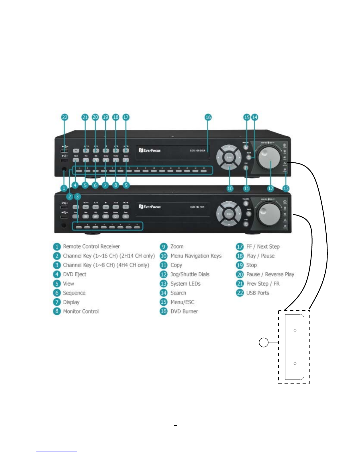
1.4 FRONT PANEL
Your primary interaction with your new DVR will be through the Front Panel buttons and their
corresponding buttons on the included IR Remote Control. Take a moment to learn where the keys are as
the remainder of the manual will refer to them often.
Figure 1-1 Front Panel
23
6

1) Remote Control Receiver: Receiver for IR remote control
2) Channel keys 1~16: Press channel key (CH1~CH16) to display that channel in full screen view.
CH1~CH14 are analog video. CH15 and CH16 are HD-CCTV video.
3) Channel keys 1~8: Press channel key (CH1~CH8) to display that channel in full screen view.
CH1~CH14 are analog video.
4) DVD Eject: Press this button to eject the DVD.
5) View: Press this key to switch between 4x, PiP (Picture In Picture),full screen, 6x, 7x, 8x, 9x, 10x, 13x
and 16x.
6) SEQ: Press this key to enter the auto sequential switching mode. The sequence dwell time can be set in
“Display Setting” tab of the Menu.
7) Display: Press this key to switch display of channels and status bar.
8) Monitor: Switch between Main monitor and Call monitor (Function reserved).
9) Zoom: In full screen mode, 2x and 4x electronic zoom. Zoom screen can be moved through arrow keys.
Pressing the Menu/ESC key again switches the electronic zoom off.
10) Menu Navigation Keys: Instead of or in combination with a mouse, you can use these keys to change
the Menu settings.
11) Copy: Press this key to enter Copy Menu
12) JOG/SHUTTLE: Shuttle (outer wheel): In playback mode, use the SHUTTLE for fast forward / fast
reverse playback.
JOG (inner wheel): In PAUSE mode, use the jog to move frame by frame. Within
menu functions, use the jog to adjust the values / parameters. Use Jog to highlight
individual cameras. Use either Shuttle or Jog to switch between MENU
Jog
parameters.
Shuttle
13) System LED
POWER: LED indicating power on
HDD: LED indicating HDD active
Alarm: LED indicating Alarm active
Network: LED for network traffic
Record: LED indicating Record active
7

14) Search: Press this key to enter Search Menu
15) Menu/ESC: Press this key to enter/exit MAIN SETUP MENU
16) DVD burner: DVD+RW burner
17) ►►/I►: Fast Forward playback or step forward playback depending on playback mode
18) ►/ I I: Forward playback or pause
19) ■ : Stop playback
20) I I / ◄: Reverse playback or pause
21) ◄I /◄◄: Fast reverse playback or step reverse playback depending on playback mode
22) USB ports: Use one port for connecting USB-Flash-Drive to copy/archive video or for firmware
upgrades. Use the other port for connecting the mouse.
23) Ear-mount: Use two M3 screws (φ6.8) to fix the ear-mount.
8
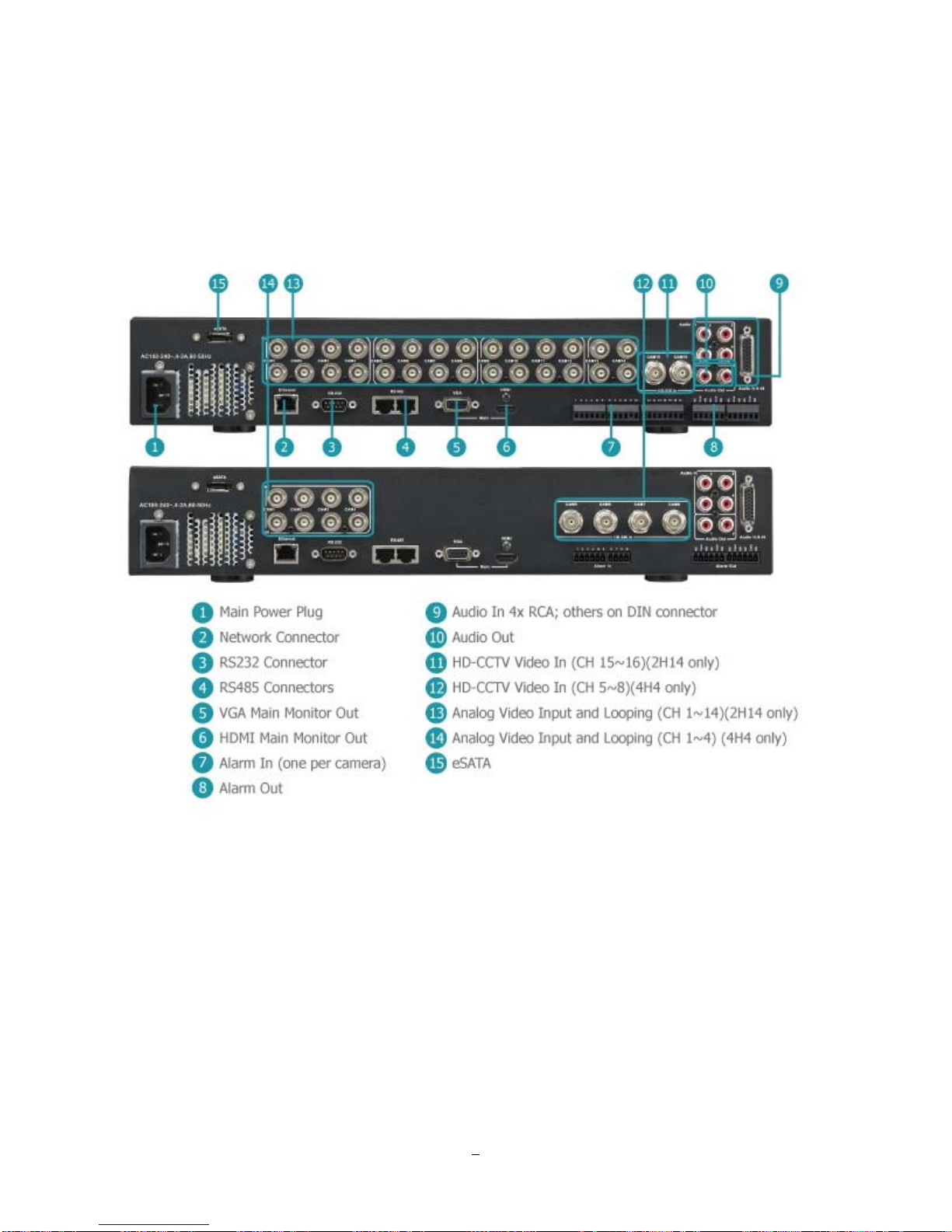
1.5 REAR PANEL
During initial setup you will be connecting your DVR to multiple input and output devices. This is done
through the rear panel.
1) Main POWER: Plug the 120~240VAC power source provided into the power socket.
2) ETHERNET: RJ-45 network connection 10/100Mbps Ethernet. There are two LEDs on the LAN jack;
Green LED means network is connected, amber LED flickers when data is being exchanged.
3) RS232 Connector: 9-pin D-Sub control input for RS-232.
4) RS485 Connectors: For remote control via RS-485 keyboards and telemetry control for attached PTZ
devices
Figure 1-2 Rear Panel
9

5) VGA Main Monitor Out: Connect a VGA monitor to the VGA output connection. DVR can auto detect
the best resolution from the connected VGA monitor. If DVR detection fails, the default resolution will be
1920x1080 60Hz vertical, 68 KHz horizontal.
6) HDMI Main Monitor Out: Provides an uncompressed all-digital video interface between the HD DVR
and HDMI-compatible monitor. HDMI output format is 1920x1080p 60Hz vertical, 68 KHz horizontal.
7) Alarm In: Connect up to 16 alarm inputs, selectable between N.O./N.C. contacts.
8) Alarm Out: N.C or N.O type alarm out (form “C”).
9) Audio In 4x RCA, others on DIN connector: Connect line level output of an audio preamplifier to the
audio input connection corresponding to the appropriate camera.
10) Audio Out: Connect to the line level input of an audio amplifier.
11) HD-CCTV Video In (CH15~16) (2H14 only): Connect HD-SDI camera’s video output (CH15~16) or
other HD-SDI video source to the video input connection.
12) HD-CCTV Video In (CH5~8) (4H4 only): Connect HD-SDI camera’s video output (CH5~8) or other
HD-SDI video source to the video input connection.
13) Analog Video Input and looping (CH1~14) (2H14 only): Connect camera’s video output (CH1~14) or
other composite video source to the video input connection.
14) Analog Video Input and looping (CH1~4) (4H4 only): Connect camera’s video output (CH1~4) or
other composite video source to the video input connection.
15) eSATA: Used for external SATA HDD bay. Note: Hot-swappable model does not support eSATA.
10
2 Installation
2.1 HD-CCTV wiring for video inputs
2.1.1 Understanding HD-CCTV signals and wiring
Even if EverFocus HD-CCT
technology - the requirements for wiring and cable types are some different.
This chapter explains some basic facts for HD-CCTV signals and cable requirements.
2.1.2 HD-CCTV signal
V equipment uses coaxial cable and BNC type plugs similar to standard CCTV
In result to the high resolution and uncompressed image transmission from the camera high frequencies
are used for HD-CCT
V signal transmission.
EverFocus HD-CCTV technology is mostly based on the SMPTE-292M standard, which defines HD-SDI
(High Definition - Serial Digital Interface) video transmission.
In classic CCTV video standards PAL/NTSC the frequency bandwidth is < 6MHz for high resolution
cameras.
HD-CCTV works with up to 1.5 GHz, so this technology requires ~ 250 times higher frequency than
PAL/NTSC based CCTV.
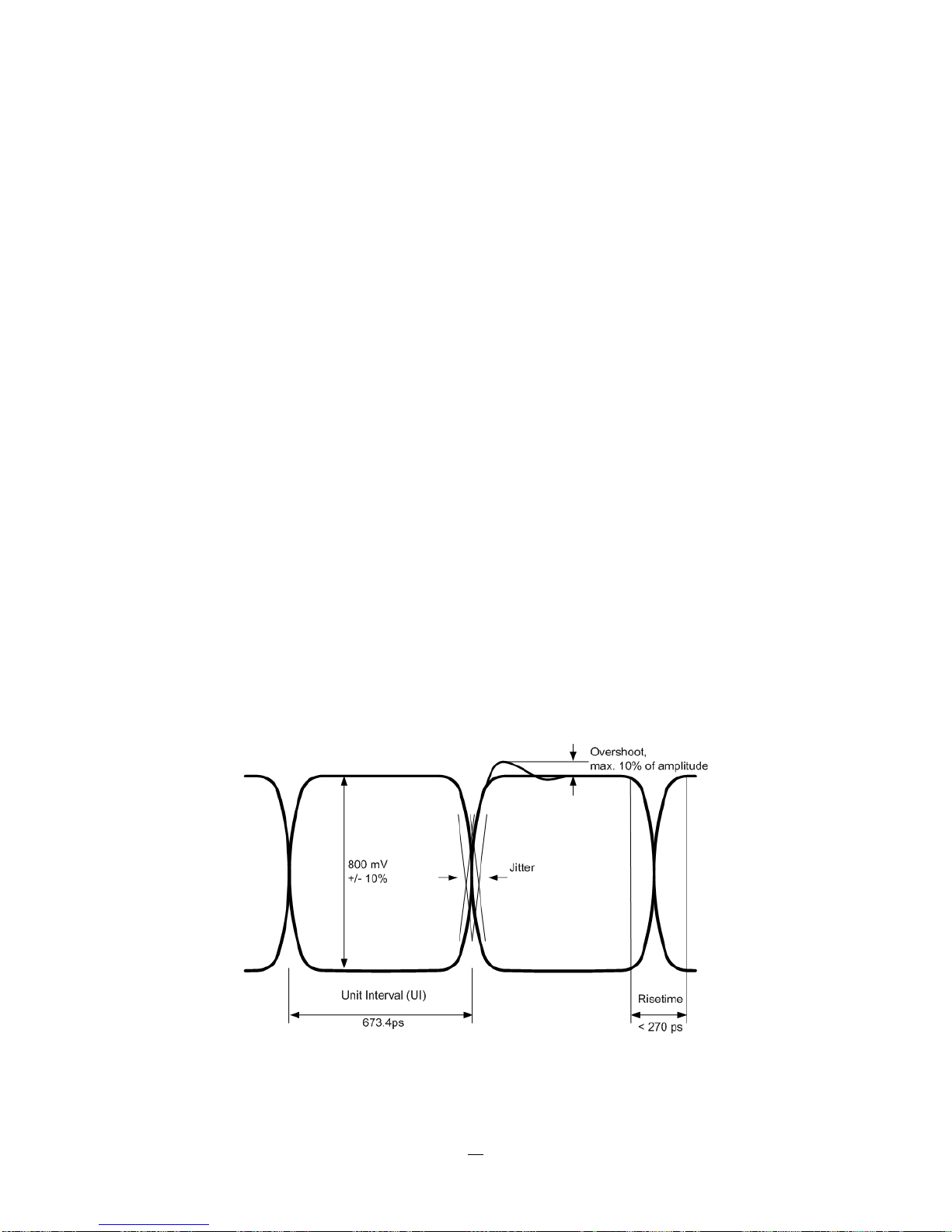
The figure below shows the basic timing and signal levels of a full HD (1920x1080) signal:
The diagram shows the total difference of HD-CCTV signals to classic NTSC or PAL signals.
Timing of HD-SDI signal ("Eye"-diagram)
11

Well known signal parts such as Sync, Burst and others do not exist here.
The high frequencies do not allow a signal evaluation by standard oscilloscopes or other standard video
measurement tools. Only quite expensive HD-SDI analyzers and upscale HF - oscilloscopes could be used
here. In most cases such equipment is not available at installation site.
For this reason a careful specification of the cable type is mandatory for system planning, especially in
applications with long cable distances.
2.1.3 Cable types
The short description of HD-SDI signals above explains, why high frequency attenuation of the used video
cable has a high influence on the achievable maximum cable length. Further on also the Return Loss of the
coaxial cable and plug influences signal stability.
The standard RG-59 cable types - the most common in the CCTV industry - are originally designed for
lower frequencies.
However, due to the new optimized receiver interfaces of EverFocus HD-CCTV equipment it is also
possible to use standard RG-59 cable for distances of over 100m.
High quality, low loss RG-59 cable types allow distances up to 160m.
Longer cable distances can be achieved with low loss RG-6 or RG-11 type coaxial cables.
Generally are cable types with 75 Ω impedance required.
Attenuation at 1 GHz: < 32 dB per 100m (328 feet)
Return Loss attenuation: > 20 dB
Impedance: 75 Ω
The table below gives an orientation for achievable cable distances:
Cable Type Attenuation in dB at 1
GHz per 100 m / 328 ft
Max. Cable distance in
m ft
RG-59 24 ~ 40 * 70 ~ 160 230~520
RG-6 15 ~ 35 * 100 ~ 190 330~620
RG-11, CATV-
8 ~ 16 * 180 ~< 250 590~<820
lowloss cables
* Low quality cable may have higher attenuation
12
2.1.4 Cable installation
Please make sure, that the coaxial cable is not squeezed at any position.
Also the max. bending radius defined by the cable manufacturer should be considered.
General rule: maximum bending radius = 10 x outer cable diameter
Bending creates pressure on the center conductor, causing it to move through the dielectric toward the
inside of the bend. This affects impedance and return loss and reduces the maximum possible cable length.
Please try to avoid any BNC - adapter or any connectors in the BNC cable.
Looping HD-SDI signals by BNC T-connectors to other devices is not possible.
2.1.5 BNC-plug
Also the BNC - plug plays an important role for clear HD-CCTV signal transmission.
Standard BNC plugs for CCTV have a quite high attenuation and may cause return losses due to reflection
effects.
We recommend using of HD-Video approved BNC plugs.
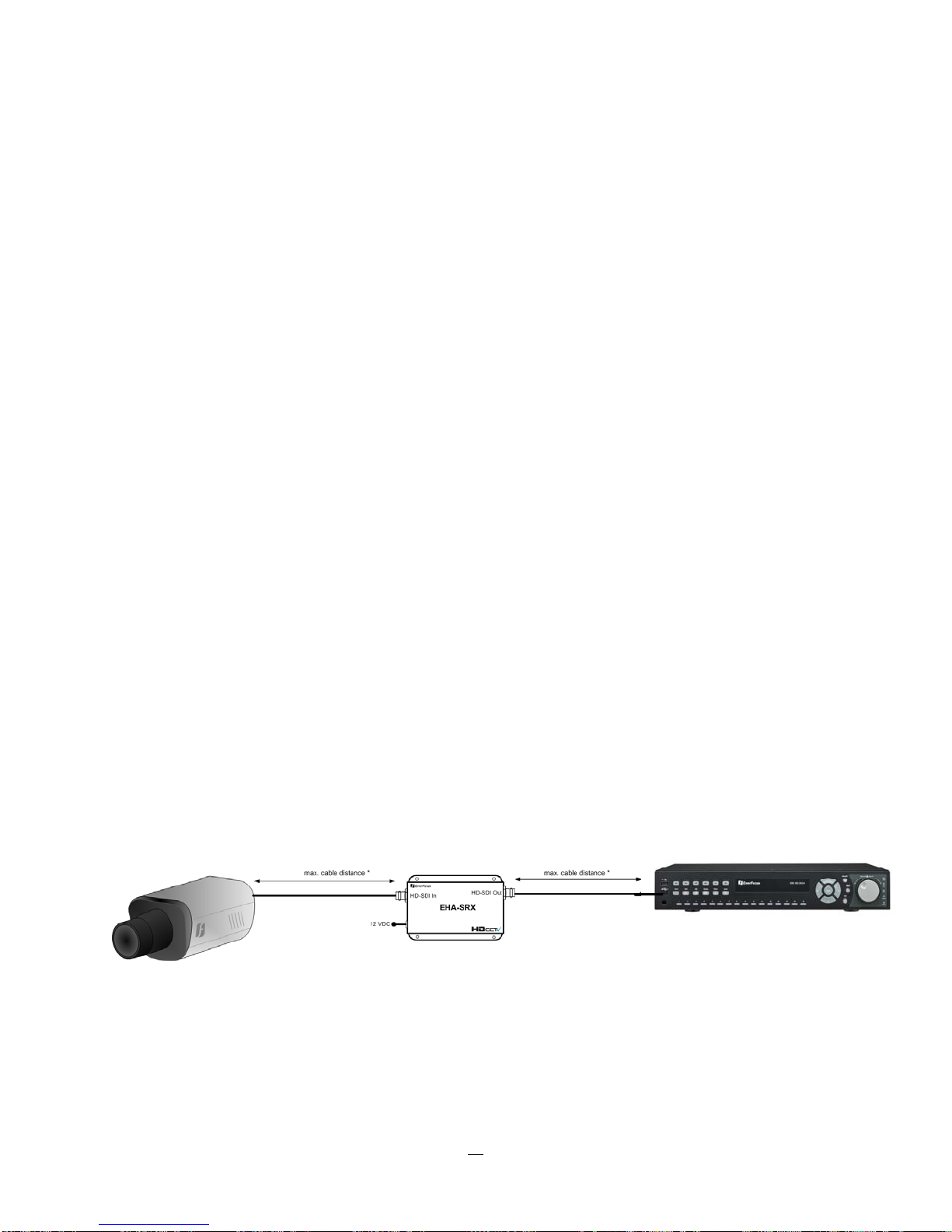
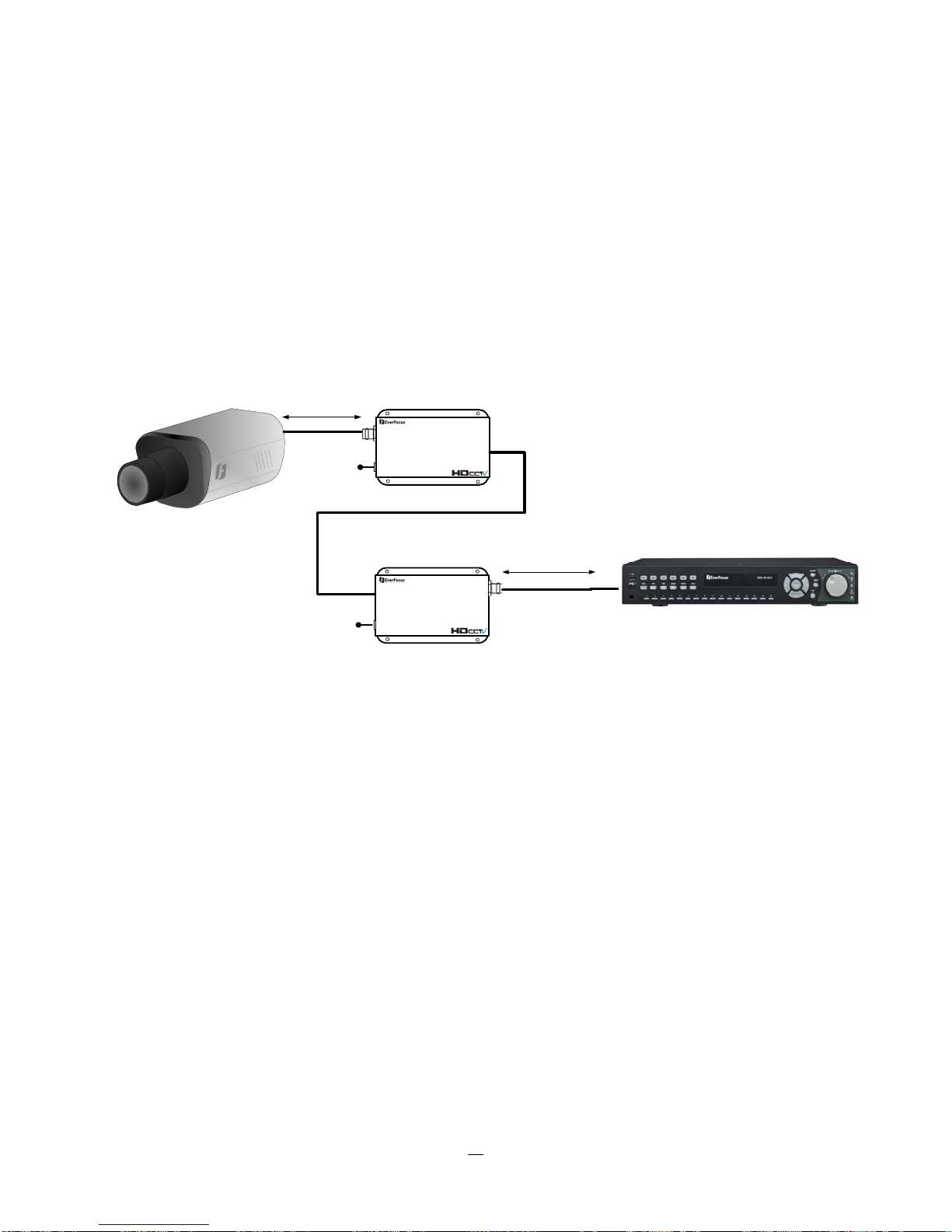
2.1.6 Extended cable lengths with repeater EHA-RPT / converter EHA-
SRX
The maximum cable distance between camera and DVR and DVR / repeater can be doubled by installing
EHA-RPT in the video line. EHA-SRX is a combined HD-SDI cable extender and HD-SDI to HDMI
converter.
The HD-SDI output of EHA-SRX allows adding one more complete coaxial cable length.
* max. coaxial cable depends on installed cable type
13
2.1.7 Extended cable lengths with fiber optics transmission
The maximum distance between camera and receiving device can be extended by fiber optics cable.
The transmitters and receivers are available for multi-mode and single-mode fiber cables:
EHA-FTX-MM: Fiber optics transmitter multi-mode, max. transmission distance 500 m
EHA-FTX-SM: Fiber optics transmitter single-mode, max. transmission distance 21 Km
EHA-RTX-MM: Fiber optics receiver multi-mode, max. transmission distance 500 m
EHA-RTX-SM: Fiber optics receiver single-mode, max. transmission distance 21 Km
max. coaxial cable distance *
12 VDC
HD-SDI In
EHA-FTX
Fiber Optical Cable
EHA-....X-MM:Multi Mode - up to 500 m
EHA-....X-SM: Single Mode: up to 21 Km
Fiber out
max. coaxial cable distance *
12 VDC
Fiber in
12 VDC
HD-SDI Out
EHA-FRX
* max. coaxial cable depends on installed cable type
The fiber optics interface of EHA-FTX / EHA-FRX requires LC type plugs for the fiber optics cable.
14
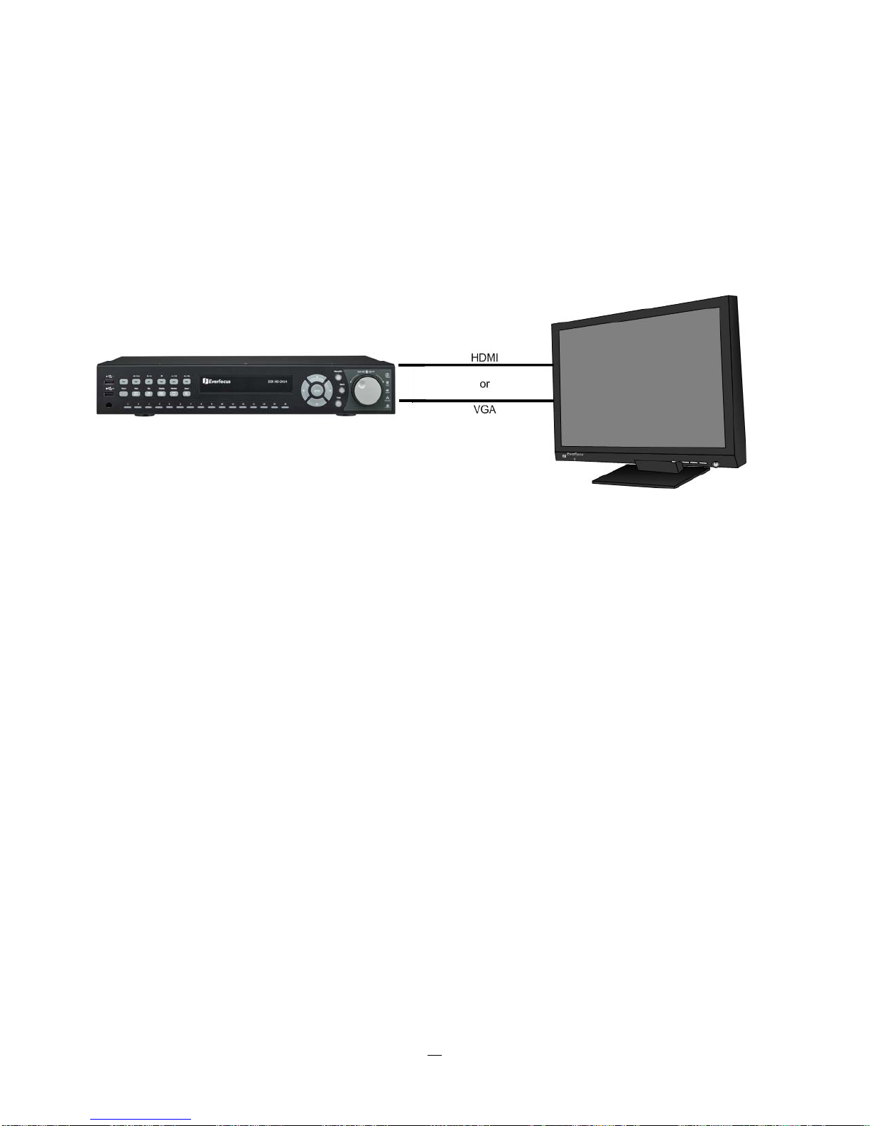
2.1.8 MONITOR INSTALLATION
The ENDEAVOR SD+HD DVR provides 2 main monitor outputs with identical functionality - VGA and HDMI.
Both outputs can be used simultaneously and deliver full HD output resolution (1920x1080, progressive, 60
Hz. vert., 68 KHz hor.).
Make sure that the connected monitor's specifications comply with these resolution requirements.
Please do not exceed the max. HDMI cable length of 15 m.
For cable length up to 3 m standard HDMI cables mostly work well, for longer distances (especially in the
15m range) please use only high quality HDMI cable.
2.2 AUDIO INSTALLATION
EDR HD-2H14 DVR provides 16 line level audio inputs and 2 line level audio outputs. EDR HD-4H4
provides 8 line level audio inputs and 2 line level audio outputs. The first 4 audio outputs are RCA
connectors, the rest are on DIN connectors.
Audio out 1 is for local audio output, whereas Audio out 2 is reserved for the audio transmitted from the
remote site back to the DVR.
ATTENTION: The direct connection of a non-amplified microphone is not supported (a microphone
amplifier is required). The audio output requires an amplifier to drive a speaker or headphones.
The installation must be connected with audio coax cable and RCA plugs.
AUDIO RECORDING FUNCTIONALITY:
15

Audio recording is activated / deactivated in the Camera Menu for Camera #1~16 respectively. Please
check and always comply with local laws and regulations when using audio recording.
The audio channel is always recorded together with video and is independent of the image recording rate.
Though the audio record control is done in the Camera #1~16 screen, there is no specific camera
allocation.
2.3 ALARM CONT A CTS INSTALLATION
The alarm inputs can be used to start recording or for recording rate adjustment. In addition, alarm
reactions such as camera display on the monitor, buzzer, e-mail and network alarm are available. The
alarm output relay can be switched if required. Alarm input response actions can be controlled according to
a flexible schedule.
2.3.1 Alarm Input Contacts
This DVR provides one alarm input per camera. All inputs are programmable N.O. (Normal Open) or N.C.
(Normal Closed) Inputs have to be switched by dry contacts.
Alarm input with N.O. (Normal Open) contact Alarm input with N.C. (Normal Closed) contact
in idle state in idle state
All settings are programmed in the ALARM menu (Section 0).
2.3.2 Alarm Output Relay
The relay output provides either Normally Open or Normally Closed dry contacts.
Output relay in idle state
2.4 RS-485 keyboard / PTZ Installation
All functions can be remote-controlled by the EKB-500 universal keyboard. Using the EEPbus protocol,
digital video recorders, keyboards and speed domes can be installed on one single RS-485 bus. One
system can comprise up to 8 keyboards.
16
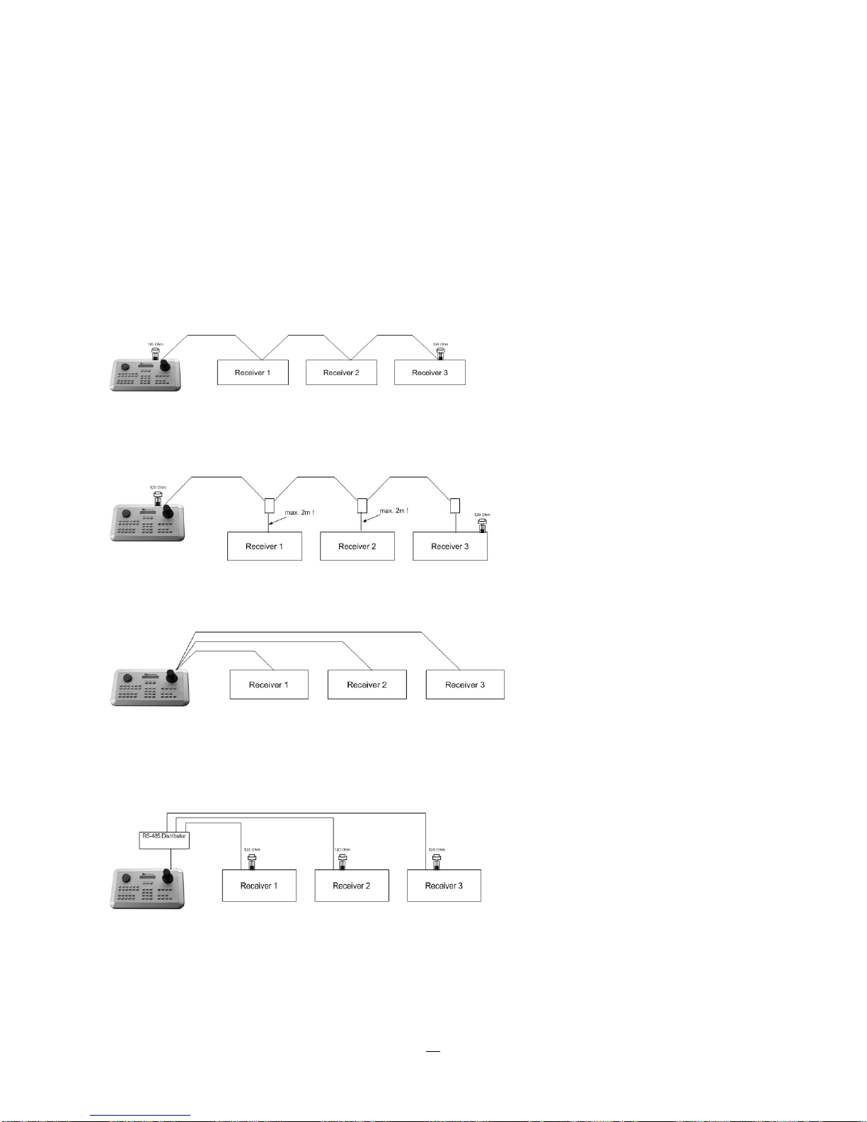
2.4.1 General RS-485 bus installation
The EKB-500 keyboard uses a RS-485 simplex wiring; the signal is transferred via a single twisted pair line.
CAT5 network cable is recommended, UTP version (unshielded) is sufficient for normal applications. A
shielded cable should be used if the installed cables are expected to be highly susceptible to interference.
The number of devices installed in one bus is limited to 32, and the maximum cable length is 3,900 feet.
Both of these can be expanded using a signal distributor EverFocus Model EDA997A (see below).
Both the first and the last device in series should be terminated with 120 Ohm resistance in order to
minimize line reflections.
RS-485 bus serial wiring
Cable length from box to device („Stubs“) has to be limited to 2m using connector boxes.
RS-485 bus serial wiring with connector boxes and connection cable
Direct RS-485 bus star wiring is not supported unless using an EverFocus Model EDA997A (see below).
Improper RS-485 bus star wiring
An EDA997A RS-485 signal distributor may be used to use a star wiring configuration.
Star wiring with RS-485 signal distributor
17
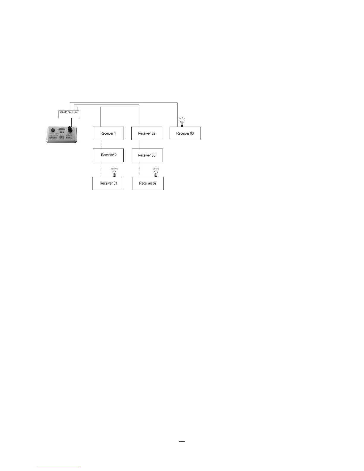
A RS-485 distributor can also be used to increase the maximum number of devices on the bus as well as
the total range. Each distributor output provides another RS-485 bus. This allows each output to extend an
additional 1200m, and it also enables the additional connection of 31 further devices to each output (the
output itself represents one device).
The maximum system expandability depends on the RS-485 address range of the installed devices.
System expansion with RS-485 signal distributor
ATTENTION: EDA997A signal distributors are unidirectional! This means that the signal only flows from
the input towards the outputs. Therefore, e.g. the interconnection of several keyboards is not possible with
these types of signal distributor!
2.4.2 RS-485 ports
This DVR provides two independent RS-485 ports with 2 RJ-45 plugs each (loop-through).
2.4.3 EKB-500 connection with network patch cable
For a simple, short distance installation, recorder and keyboard can be connected directly using a standard
CAT5 network cable with an 8-pin connector at only one end, and at the other end the Pin 3 wire connected
to RS485 “+” (plus) and the pin 6 wire connected to RS-485 “-“ (minus).
2.4.4 EKB-500 connection to several DVRs
For long distance installations connecting several DVRs, please use an EDA997A signal distributor to
connect. For further details on keyboard connection, please refer to the EKB-500 manual.
RS-485 port communication settings are configured in the I/O CONTROL menu (Section 5.10.4 System
Setup: I/O - control).
2.4.5 Speed Dome Installation
Speed dome or telemetry receiver pan/tilt/zoom control is available through web browser or the optional
PowerCon software if the DVR is connected to a network. Local telemetry control is provided by USB mouse control or by the optional EKB-500 keyboard.
Supported protocols: EverFocus, Pelco-D, Pelco-P, Samsung, Transparent
18
Required DVR settings: RS-485 receiver address in CAMERA menu
(Section 4.3)
RS-485 parameters and protocol in the I/O CONTROL menu
(Section 5.10.4)
ATTENTION: Some Pelco-
D / -P protocol domes and receivers require an address offset of -1, i.e. the
address assigned to the dome / receiver in the DVR camera menu must be 1 below the address set in the
dome / receiver itself!
2.5 USB-Mouse installation
Connect the USB mouse to one of the 2 USB ports. (This can be done while DVR is powered on) The rear
USB V1.0 port is recommended to reserve the higher speed front USB V2.0 port for video copy/export.
NOTE: Recommended mouse types are Logitech® and Microsoft® wired USB wheel-mouse. Wireless
USB mouse is not supported.
2.6 NETWORK CONNECTION
This section only describes physical connection to an Ethernet network. This step must be completed
before the DVR can connect to the network. There are two basic types of connection:
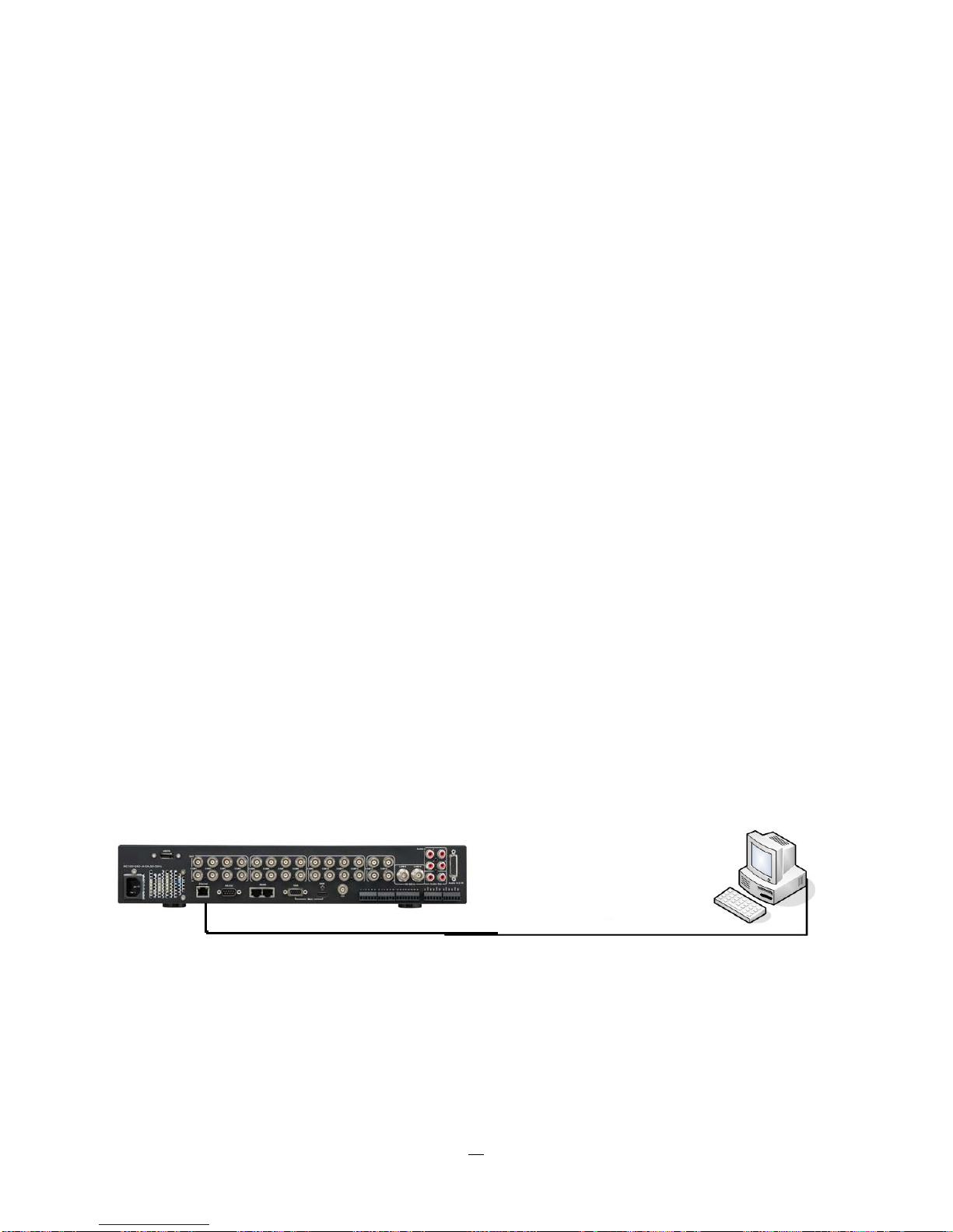
2.6.1 Direct PC Connection through Crossover Network Cable
The point-to-point connection of DVR and PC requires a crossover (crossed) network cable. This type of
connection is ONLY used for direct connection to a single PC. Make sure that the PC is equipped with a
10/100Mbps compatible network connection.
Figure 2-1 Direct PC Connection
19
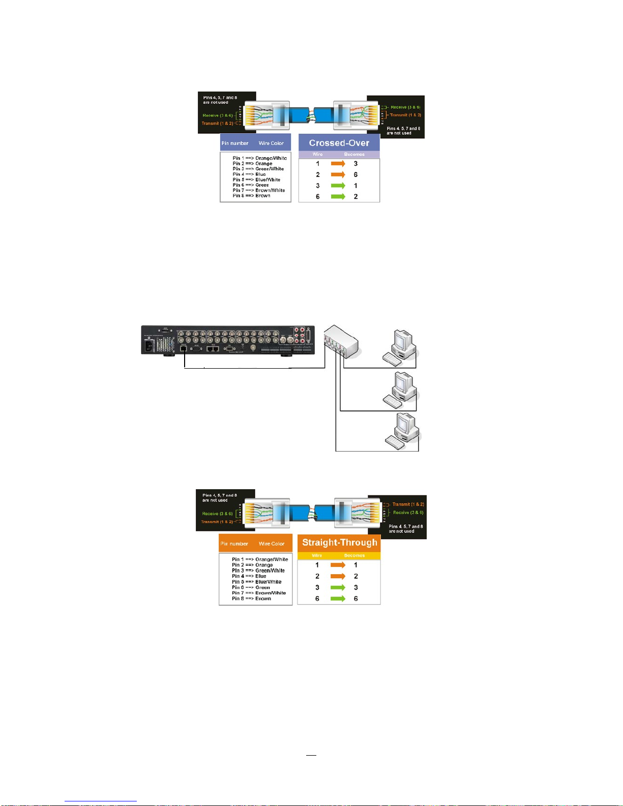
Pinout of crossover-cable
2.6.2 Network Connection through Patch Cable
The connection to an existing network requires a normal patch cable (straight-through). Th
shows the connection to a network switch or router.
Figure 2-2 Network Connection through Patch Cable
e illustration
Pinout of straight patch cable
20

2.7 FINAL INSTALL PROCESS
Once you have completed the basic wiring connections, you are ready to turn on the DVR. Simply plug in
the power source. The POWER LED will light up if power is normal. Once the system has finished loading,
you can begin to set up the menu options for the DVR.
21
 Loading...