

EverFocus ENDEAVOR 264X4 User Manual
User Manual
E
E
N
N
D
D
E
E
AVV
A
O
R 226644
O
R
X44
X
DVV
D
R
R

EVERFOCUS ELECTRONICS CORPORATION
ENDEA VOR 264X4 D VR
Instruction Manual
2010 EverFocus Electronics Corp
www.everfocus.com
All rights reserved. No part of the contents of this manual may be reproduced or transmitted in any form or by
any means without written permission of the Everfocus Electronics Corporation.
Release Date: Jan. 2011
QuickTime is a registered trademark of the Apple Computer, Inc.
Windows is a registered trademark of the Microsoft Corporation.
Linksys is a registered trademark of the Linksys Corporation.
D-Link is a registered trademark of the D-Link Corporation.
DynDNS is a registered trademark of the DynDNS.org Corporation.
Other product and company names mentioned herein may be the trademarks of their respective owners.

Safety Precautions
Refer all work related to the installation of this product to qualified service personnel or system
installers.
Do not block the ventilation openings or slots on the cover.
Do not drop metallic parts through slots. This could permanently damage the appliance. Turn the
power off immediately and contact qualified service personnel for service.
Do not attempt to disassemble the appliance. To prevent electric shock, do not remove screws or
covers. There are no user-serviceable parts inside. Contact qualified service personnel for
maintenance. Handle the appliance with care. Do not strike or shake, as this may damage the
appliance.
Do not expose the appliance to water or moisture, nor try to operate it in wet areas. Do take immediate
action if the appliance becomes wet. Turn the power off and refer servicing to qualified service
personnel. Moisture may damage the appliance and also may cause electric shock.
Do not use strong or abrasive detergents when cleaning the appliance body. Use a dry cloth to clean
the appliance when it is dirty. When the dirt is hard to remove, use a mild detergent and wipe gently.
Do not overload outlets and extension cords as this may result in a risk of fire or electric shock.
Do not operate the appliance beyond its specified temperature, humidity or power source ratings. Do
not use the appliance in an extreme environment where high temperature or high humidity exists. Use
the DVR at indoor type temperatures within 0°C~40°C (32°F~104°F) and at relative humidity between
20%~80%. The input power source for this device is 12VDC though a power supply which operates
from100~240VAC.
Read Instructions
All the safety and operating instructions should be read before the unit is operated.
Retain Instructions
The safety and operating instructions should be retained for future reference.
Heed Warnings
All warnings on the unit and in the operating instructions should be adhered to.
Follow Instructions
All operating and use instructions should be followed.
Cleaning
ii

y
Unplug the unit from the outlet before cleaning. Do not use liquid cleaners, abrasive or aerosol
cleaners. Use a damp cloth for cleaning
Attachments
Do not use attachments not recommended by the product manufacturer as they may cause hazards.
Water and Moisture
Do not use this unit near water-for example, near a bath tub, wash bowl, kitchen sink, or laundry tub,
in a wet basement, near a swimming pool, in an unprotected outdoor installation, or any area which is
classified as a wet location.
Servicing
Do not attempt to service this unit by yourself as opening or removing covers may expose you to
dangerous voltage or other hazards. Refer all servicing to qualified service personnel.
Power Cord Protection
Power supply cords should be routed so that they are not likely to be walked on or pinched by items
placed upon or against them, playing particular attention to cords and plugs, convenience receptacles,
and the point where they exit from the appliance.
Object and Liquid Entry
Never push objects of any kind into this unit through openings as they may touch dangerous voltage
points or short-out parts that could result in a fire or electric shock. Never spill liquid of any kind on the
unit.
ATTENTION! This is a class A product which may cause radio interference in a domestic environment; in
this case, the user ma
be urged to take adequate measures.
Federal Communication Commission Interference Statement
This equipment has been tested and found to comply with the limits for a Class B digital device, pursuant to
Part 15 of the FCC Rules. These limits are designed to provide reasonable protection against harmful
interference in a residential installation. This equipment generates, uses and can radiate radio frequency
energy and, if not installed and used in accordance with the instructions, may cause harmful interference to
radio communications. However, there is no guarantee that interference will not occur in a particular
installation. If this equipment does cause harmful interference to radio or television reception, which can be
determined by turning the equipment off and on, the user is encouraged to try to correct the interference by
one of the following measures :
•Reorient or relocate the receiving antenna.
•Increase the separation between the equipment and receiver.
•Connect the equipment into an outlet on a circuit different from that to which the receiver is connected.
•Consult the dealer or an experienced radio/TV technician for help.
FCC Caution: Any changes or modifications not expressly approved by the party responsible for compliance
could void the users’ authority to operate this equipment.
iii

WEEE
This Product is RoHS compliant.
The information in this manual was current upon publication. The manufacturer reserves the right to revise and improve his products.
Therefore, all specifications are subject to change without prior notice. Manufacturer is not responsible for misprints or typographical
errors.
Please read this manual carefully before installing and using this unit. Be sure to keep it handy for later reference.
iv

TABLE OF CONTENTS
1 PRODUCT OVERVIEW ..................................................................................................... 1
1.1 FEATURES....................................................................................................................... 1
1.2 PACKAGE CONTENTS................................................................................................... 3
1.3 SPECIFICATIONS ........................................................................................................... 4
1.4 FRONT PANEL ................................................................................................................6
1.5 REAR PANEL................................................................................................................... 9
1.6 MONITOR INSTALLATION......................................................................................... 11
1.7 AUDIO INSTALLATION ..............................................................................................11
1.8 ALARM CONTACTS INSTALLATION....................................................................... 12
1.8.1 Alarm Input Contacts............................................................................................................................12
1.8.2 Alarm Output Relay...............................................................................................................................12
1.9 RS-485 KEYBOARD / PTZ INSTALLATION......................................................................... 12
1.9.1 General RS-485 bus installation ...........................................................................................................12
1.9.2 RS-485 socket pin assignment...............................................................................................................14
1.9.3 EKB-500 connection with network patch cable.....................................................................................14
1.9.4 EKB-500 connection to several DVRs...................................................................................................14
1.9.5 Speed Dome Installation .......................................................................................................................14
1.10 USB-MOUSE INSTALLATION.......................................................................................... 15
1.11 NETWORK CONNECTION........................................................................................ 15
1.11.1 Direct PC Connection through Crossover Network Cable ...................................................................15
1.11.2 Network Connection through Patch Cable............................................................................................16
1.12 FINAL INSTALL PROCESS....................................................................................... 17
2 MOUSE AND FRONT PANEL OPERATION ............................................................... 18
2.1 GENERAL USB MOUSE OPERATION....................................................................... 18
2.1.1 How to select a channel / Enable audio................................................................................................18
2.1.2 OSD Root Menu.....................................................................................................................................18
2.1.3 Operation in the Configuration Menus.................................................................................................19
2.1.4 Field Input Options ...............................................................................................................................19
2.2 G
2.2.1 How to select a channel / Enable audio.......................................................................................................21
2.2.2 OSD Root Menu ...........................................................................................................................................21
2.2.3 Front Panel Key Review...............................................................................................................................21
2.2.4 Operation in Configuration Menu.........................................................................................................21
2.2.5 Field Input Options ...............................................................................................................................22
ENERAL FRONT PANEL OPERATION ...............................................................................21
3. GENERAL DVR OPERATIONS...................................................................................... 24
3.1 RECORD......................................................................................................................... 24
3.2 LOGIN............................................................................................................................. 24
3.3 SELECT CAMERA OPERATION................................................................................. 25
3.5 PLAYBACK.................................................................................................................... 26
v

3.6 PTZ.................................................................................................................................. 27
3.6.1 General PTZ control (if PTZ cameras are installed)..................................................................................27
3.6.2 Express Control of PTZ.........................................................................................................................28
3.7 LAYOUT......................................................................................................................... 30
3.7.1 Bring a camera to full screen mode.......................................................................................................30
3.8 CHANNEL
SWITCHING............................................................................................... 30
3.9 DISPLAY ........................................................................................................................ 31
3.10 SEQUENCE.................................................................................................................. 31
3.11 ZOOM........................................................................................................................... 31
3.12 SEARCH....................................................................................................................... 32
3.12.1 Time Search...........................................................................................................................................33
3.12.2 Event Search..........................................................................................................................................33
3.12.3 Smart Search .........................................................................................................................................34
3.12.4 Snapshot Search ....................................................................................................................................37
3.13 COPY............................................................................................................................ 39
3.14 LOGOUT...................................................................................................................... 40
4 DVR CONFIGURATION .................................................................................................. 41
4.1 CONFIGURATION MENU............................................................................................ 41
4.2 EXPRESS........................................................................................................................ 41
4.3 CAMERA SETTING ...................................................................................................... 44
4.3.1 Basic Setting..........................................................................................................................................44
4.3.2 Video Adjust ..........................................................................................................................................47
4.3.3 Motion ...................................................................................................................................................48
4.3.4 Video Loss.............................................................................................................................................51
4.4 RECORD & PLAY SETTING........................................................................................ 52
4.4.1 Record...................................................................................................................................................53
4.4.2 Built-in Calculator ................................................................................................................................53
4.4.3 Play .......................................................................................................................................................55
4.5 ALARM & EVENT SETTING....................................................................................... 56
4.5.1 Alarm .....................................................................................................................................................56
4.5.2 Event......................................................................................................................................................58
4.6 SCHEDULE
4.6.1 Express Setup .......................................................................................................................................66
4.6.2 Holidays ................................................................................................................................................67
4.6.3 Schedule ................................................................................................................................................68
4.6.4 Alarm Action .........................................................................................................................................74
SETTING................................................................................................... 66
4.7 NETWORK SETTING.................................................................................................... 78
4.7.1 LAN .......................................................................................................................................................78
4.7.2 EMAIL...................................................................................................................................................80
4.7.3 DDNS ....................................................................................................................................................81
4.7.4 Alarm Server .........................................................................................................................................83
4.7.5 Network Test..........................................................................................................................................84
4.8 DISK
4.8.1 Disk .......................................................................................................................................................85
4.8.2 Lock/Format..........................................................................................................................................86
INFORMATION................................................................................................... 85
4.9 DISPLAY SETTING....................................................................................................... 87
4.9.1 Monitor OSD.........................................................................................................................................87
4.9.2 Main M/T SEQ ......................................................................................................................................88
vi

4.9.3 Call M/T SEQ........................................................................................................................................89
4.10 SYSTEM SETTING..................................................................................................... 90
4.10.1 Date/Time..............................................................................................................................................90
4.10.2 Daylight Saving.....................................................................................................................................91
4.10.3 User.......................................................................................................................................................92
4.10.4 I/O Control ............................................................................................................................................95
4.10.5 Misc. ......................................................................................................................................................96
4.11 INFORMATION........................................................................................................... 98
4.11.1 System....................................................................................................................................................98
4.11.2 Log.........................................................................................................................................................99
5 NETWORKING OVERVIEW ........................................................................................ 101
5.1 INTRODUCTION TO TCP/IP............................................................................................. 101
5.2 SUBNET MASKS.............................................................................................................. 101
5.3 GATEWAY ADDRESS....................................................................................................... 101
5.4 VIRTUAL PORTS.............................................................................................................. 102
5.5 PRE-INSTALLATION ........................................................................................................ 102
5.6 WHAT IS YOUR NETWORK SETUP?.................................................................................. 103
5.7 SIMPLE ONE TO ONE CONNECTION................................................................................. 104
5.8 DIRECT HIGH SPEED MODEM CONNECTION ................................................................... 109
5.9 ROUTER OR LAN CONNECTION...................................................................................... 111
6 REMOTE OPERATION FROM BROWSER.................................................................... 114
6.1 CONNECTING TO ENDEAVOR..................................................................................... 114
6.2 BROWSER SECURITY SETTING .................................................................................. 115
6.2.1 Installing ActiveX controls..................................................................................................................115
6.2.2 Enabling ActiveX Controls..................................................................................................................118
6.3 REMOTE LIVE VIEW................................................................................................. 121
6.4 REMOTE PLAYBACK................................................................................................ 123
7 EVERFOCUS DDNS SETUP .......................................................................................... 124
8 LINKSYS & D-LINK PORT FORWARDING ............................................................. 126
8.2 TYPICAL LINKSYS PORT FORWARDING............................................................. 126
8.3 TYPICAL
9 TROUBLESHOOTING
D-LINK PORT FORWARDING ................................................................ 128
................................................................................................... 131
APPENDIX A: TIMING OF ALARM MODES.................................................................... 133
APPENDIX B: EXPRESS SETUP RECORDING VALUE SELECTION RULES
.......... 136
APPENDIX C: REMOTE CONTROL................................................................................... 138
vii

Chapter
1
1 PRODUCT O VERVIEW
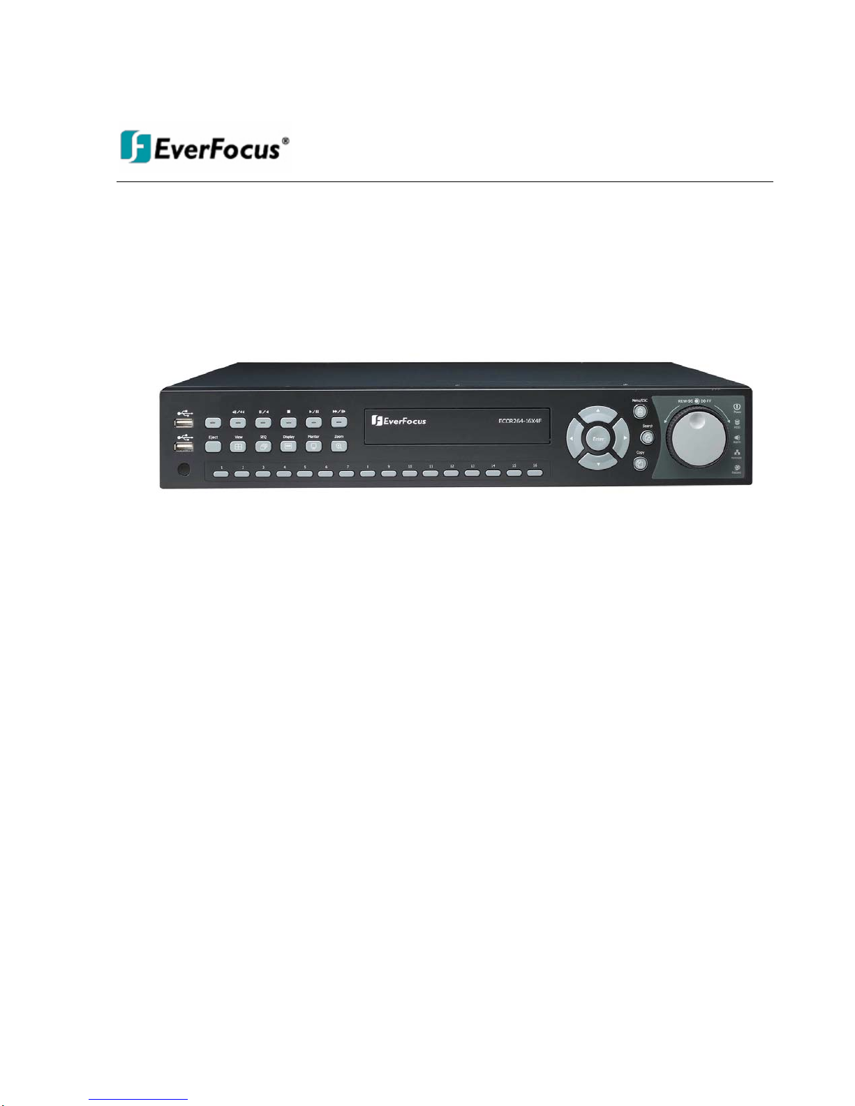
The introduction of the ENDEAVOR264 adds the advantages of H.264 compression to the power and
flexibility of the already popular ENDEAVOR DVR. State of the art H.264 compression techniques enhance
recorded video storage capacity and conserve network transmission bandwidth while maintaining high
image quality. This powerful DVR is capable of real time recording at full 4CIF resolution on all 16 channels.
Plus, the ability to independently configure image resolution and frame rate for individual cameras allows
some cameras to be recorded at D1 while others are set at CIF or 2CIF to optimize the recording
parameters for each application. Viewing live or recorded video, the full HD 1080p display proves superior
clarity on a massive scale, allocating two megapixels of resolution to the main monitor display. HDMI digital
output renders stunning images from any source, and enhances motion reproduction to deliver smoother
and crisper looking video.
The new enhanced color Graphical User Interface (GUI) makes configuration over the network, from the
front panel or with the included mouse fast and easy. An Express Setup option allows rapid configuration of
time & date, global recording settings and network configuration from a single screen. Choose from
continuous, event or schedule recording, or pick the number of days you want to record and the Express
Setup does the rest. View live, play back recorded video and configure the DVR remotely over a LAN or
WAN with the included web browser interface; check your home or business on the go from a cell phone or
PDA – the ENDEAVOR264 supports multiple remote access methods.
On playback, in addition to traditional date/time and event searches ENDEAVOR DVR also provides
powerful Smart and Snapshot Search functions. Review recorded video and let the DVR identify motion in
area(s) of interest during playback, or choose a starting date/time, an interval and direction and view a
series of snapshots extracted from recorded video to quickly isolate and play back relevant video for
efficient review of significant activities.
1.1 FEA TU RES
- D1 real time recording rate and playback rate for all cameras
- H.264 Compression format for efficient disk utilization and network bandwidth conservation
- Real time recording rate and playback rate for all cameras
- Normal and event recording frame rate can be set independently for each camera
- Recording resolution can be changed at different times of the day via schedule
- Multiple Main Monitors: VGA / HDMI (Max:1920X1080) Main monitor outputs
- Call monitor: additional composite BNC output with multiplex and/or sequenced views
1

- Simultaneous recording at D1 or 2CIF with real time streaming at CIF for remote web viewing to conserve
bandwidth
- Pentaplex Operation (Simultaneous live, recording, playback, archiving and remote viewing)
- Free EverFocus DDNS Service - static IP address is not required for reliable remote access
- User friendly GUI with graphical icons and visual indicators
- Supports eSATA (EDA450; optional)
- Supports 3GPP for mobile monitoring
- Gigabit Ethernet interface for remote network viewing and control
- Audio recording capabilities on all channels
- Multiple Control Inputs: mouse/front panel/IR remote controller (included)/EKB500 keyboard/web interface
- Built-in record time calculator for fast recording estimation
- Express Setup: A unique menu option for quick & easy installation
- Express Archive: Archive video instantly (to USB) while playing back
- Express Playback: Simply point, click and drag the playback bar to view desired recordings
- Express Search: Use the intuitive playback bar with simple drag & drop operations
- Smart Search: Identify movement from recorded video within the specified area
- Snapshot search: Show snapshots from recorded video at a specified interval to quickly locate significant
events
- Remote configuration support from the built-in web interface
- 10/100M Ethernet interface for remote network viewing and control
- On-screen PTZ control via mouse or front panel
- Support for up to 4 fixed internal HDD.
- Built-in DVD burner*
- 2 USB 2.0 ports (located on front panel) for video archive and mouse usage
- Multi-language support
- Watermark capabilities to identify intentional modifications to exported data
- 19” Rack mountable
- USB Mouse, rack mount ears and IR remote control included
*Feature may not be available on all models
2

1.2 PACKA GE CONTENTS
Standard Package
-Digital Video Recorder x1
-User Manual x 1
-Power Cord x1
-Mouse x 1
-19” Rack mounting adapters (pair) x 1
-Terminal Block x 5
-IR Remote Control x 1
-Battery x 2
-Audio-in connector (D-sub to RCA) x 1
-HDD Fixing Bracket x 4 set
-SATA cable x 4
-Screws x 16 for HDD
-Screws x 8 for HDD fixing bracket
3

1.3 SPECIFICA TIO NS
Endeavor264X4
Number of Channels 16
Compression Format H.264
Recording Rate/Resolution (Max)
Playback Rate/Resolution
Dual Streaming for remote viewing 480 NTSC / 400 PAL (CIF)
Mobile View Support
Pentaplex Operation Simultaneous Live, Recording, Playback, Archive and Remote Viewing
Video Inputs 16 BNC (NTSC/PAL automatic selection)
Looping Video Outputs 16 BNC, auto terminating
Main Monitor Outputs HDMI (1080p), VGA (1080P)
Call Monitor Output BNC (NTSC/PAL; follows input type)
Audio Inputs 16 total: 4xRCA; 12 on DIN connector (supplied); Line level.
Audio Outputs 2xRCA; Line level
Recording Modes Manual, Schedule and Event; or, choose Number of Days
Playback Search Date/Time, Event, Motion in Recorded Video, snapshot by Interval
Alarm Inputs 16 inputs
Alarm Out 4 form “C” (SPDT) relays; 30VDC@1A rating
Video Pause Yes
Video Loss Detection Yes
Motion Detection Yes
Event Log Yes
Watch Dog Timer Yes
Internal HDD 4 Internal SATA HDD
External HDD 1 eSATA (Model EDA450; optional)
Built-in DVD Burner DVD Burner (Optional)
User Interface GUI(Graphical User Interface)
OS Embedded Linux
Network/Protocol Gigabit Ethernet; TCP-IP / DHCP/ PPPoE / DDNS
Control PTZ via OSD Yes (via both local and remote interfaces)
USB 2 USB 2.0 port (on Front Panel)
Schedule Setting Supports Express and Advanced Schedule Setting
User Access 3 Levels of User Access Defined
RS-232 9-pin D-Sub socket (male)
RS-485 RJ45x2 for DVR control input and PTZ control output; data loops through
Power Source 100~240VAC ,110W max
Live view on PDA or smart phone browsers, plus various web browsers
480 NTSC /400 PAL (D1)
480 NTSC /400 PAL (Half D1)
480 NTSC /400 PAL (CIF)
480 NTSC /400 PAL (D1)
480 NTSC /400 PAL (Half D1)
480 NTSC /400 PAL (CIF)
Mobile Focus apps for iPhone, Android and others
4

Dimensions (L x W x H) 430 x 423 x 72 mm / 16.93" x 16.65" x 3.13"
Temperature 0°C~40°C / 32°F~104°F (20~80% humidity)
Certificates CE, FCC, UL
Supported PTZ Protocols EverFocus, Pelco D, Pelco P, Samsung, Transparent
5
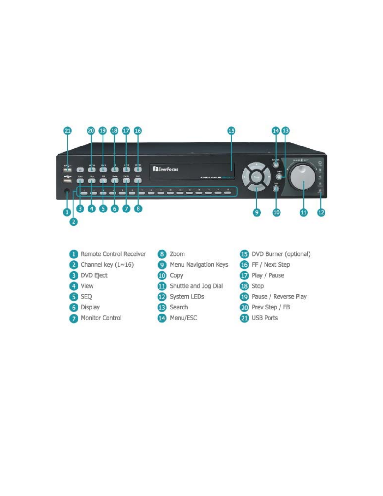
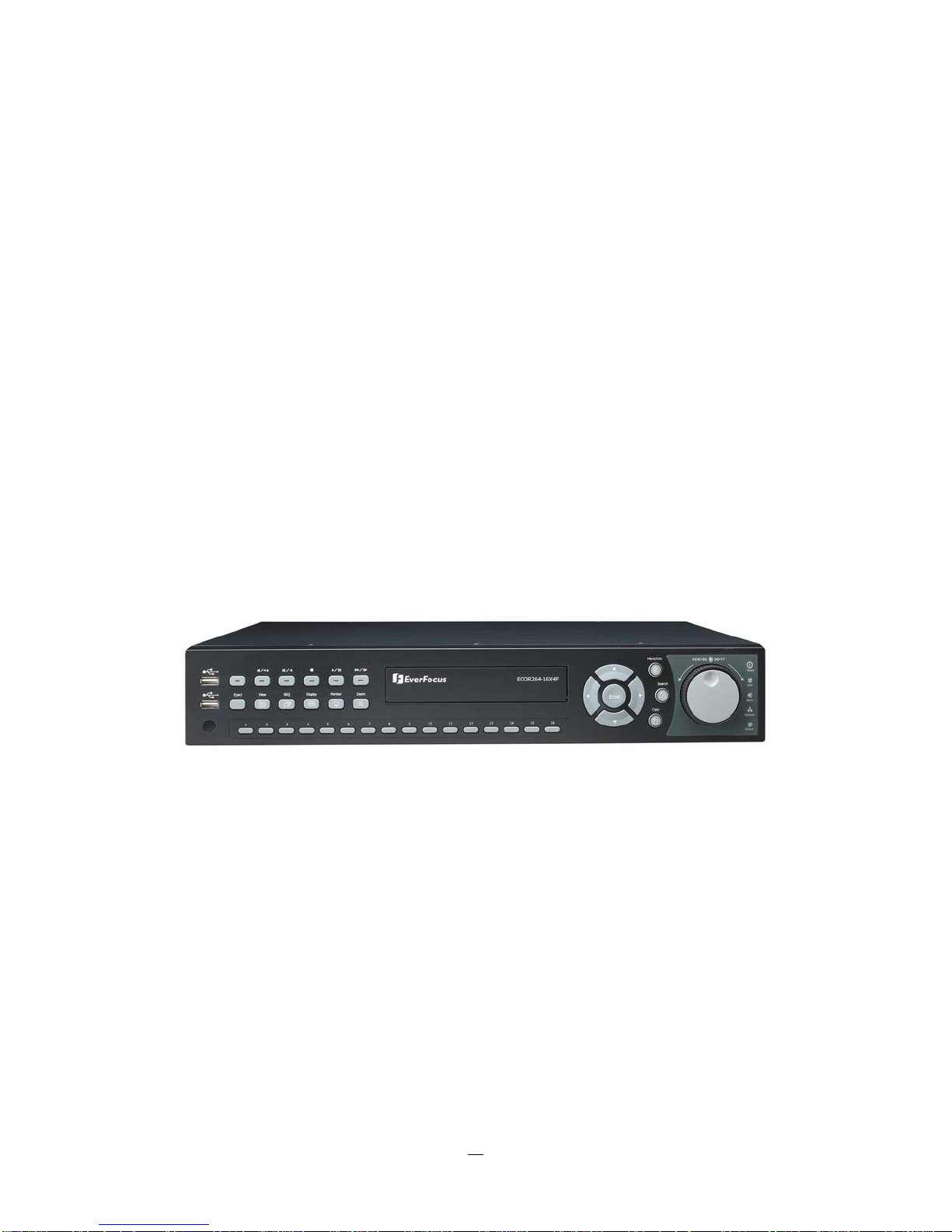
1.4 FRONT PANEL
Your primary interaction with your new DVR will be through the Front Panel buttons and their
corresponding buttons on the included IR Remote Control. Take a moment to learn where the keys are as
the remainder of the manual will refer to them often.
1) Remote Control Receiver: Receiver for IR remote control.
2) Channel keys 1~16: Press channel key (CH1~CH16)to display that channel in full screen view.
3) DVD Eject: Press this button to eject the DVD.
4) View: Press this key to switch between 4x, PiP (Picture In Picture),full screen, 9x, 10x, 13x and 16x.
Note: PIP display is not available in playback mode.
Figure 1-1 Front Panel
6

5) SEQ: Press this key to enter the auto sequential switching mode. The sequence dwell time can be set
in “Display Setting” tab of the Menu. For more detail about SEQ, please see “Section 4.9.2 Display
Setting-Main M/T SEQ”.
6) Display: Press this key to switch display of channels and status bar.
7) Monitor: Switch between Main monitor and Call monitor.
8) Zoom: In full screen mode, 2x electronic zoom. Zoom screen can be moved through arrow keys.
Pressing the zoom key again switches the electronic zoom off.
9) Menu Navigation Keys: Instead of or in combination with a mouse, you can use these keys to
change the Menu settings.
10) Copy: Press this key to enter Copy Menu. For more detail about Copy function, please see “Section
3.13 Copy”.
11) JOG/SHUTTLE: Shuttle (outer wheel): In playback mode, use the SHUTTLE for fast forward / fast
reverse playback.
JOG (inner wheel): In PAUSE mode, use the jog to move frame by frame. Within
menu functions, use the jog to adjust the values / parameters. Use Jog to highlight
Jog
Shuttle
individual cameras.
Use either Shuttle or Jog to switch between MENU parameters.
12) System LED
POWER: LED indicating power on.
HDD: LED indicating HDD active
Alarm: LED indicating Alarm active.
Network: LED for network traffic.
Record: LED indicating Record active.
13) Search: Press this key to enter Search Menu. For more detail about the Search function,
please see “Section 3.12 Search”.
14) Menu/ESC:
Press this key to enter/exit MAIN SETUP MENU.
15) DVD burner: DVD+RW burner for DVD model. (D models only) (Replaced by hot swap drive on
“R” models).
16) ►►/I►: Fast Forward playback or step forward playback depending on playback mode.
17) ►/ I I: Forward playback or pause
7

18) ■ Stop playback
19) I I / ◄: Reverse playback or pause
20) ◄I /◄◄: Fast reverse playback or step reverse playback depending on playback mode.
21) USB ports: For connecting USB-Flash-Drive to copy/archive video or for firmware upgrades.
8
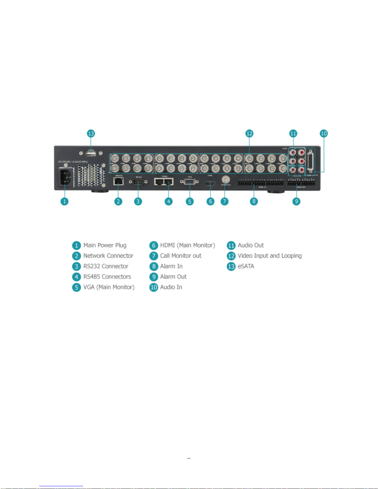
1.5 REAR PANEL
During initial setup you will be connecting your DVR to multiple input and output devices. This is done
through the rear panel.
1
○
POWER: Plug the 120~240VAC power source provided into the power socket.
2
○
ETHERNET: RJ-45 network connection 10/100Mbps Ethernet. There are two LEDs on the LAN jack;
Green LED means network is connected, amber LED flickers when data is being
exchanged.
3
○
RS232 socket: 9-pin D-Sub control input for RS-232.
4
○
RS485 socket: For remote control via RS-485 keyboards and telemetry control for attached PTZ
devices
Figure 1-2 Rear Panel
9

5
○
VGA Out: Connect a VGA monitor to the VGA output connection. DVR can auto detect the best
resolution from the connected VGA monitor. If DVR detection fails, the default
resolution will be 1920x1080 60Hz vertical, 68 KHz horizontal.
6
○
HDMI Out: Provides an uncompressed all-digital video interface between the HD DVR and HDMI-
compatible monitor. HDMI output format is 1920x1080p 60Hz vertical, 68 KHz horizontal.
7
○
Call: Call monitor output. Spot monitor for full screen live display, sequence mode and alarm
camera switching.
8
○
Alarm In: Connect up to 4 alarm inputs, selectable between N.O./N.C. contacts.
9
○
Alarm Out: N.C or N.O type alarm out (form “C”).
10
○
Audio In: Connect line level output of an audio preamplifier to the audio input connection
corresponding to the appropriate camera.
11
○
Audio Out: Connect to the line level input of an audio amplifier.
12
○
Video In: Connect camera’s video output or other composite video source to the video input
connection.
13
○
eSATA: Used for external SATA HDD bay. Note: Hot-swappable model does not support eSATA.
10
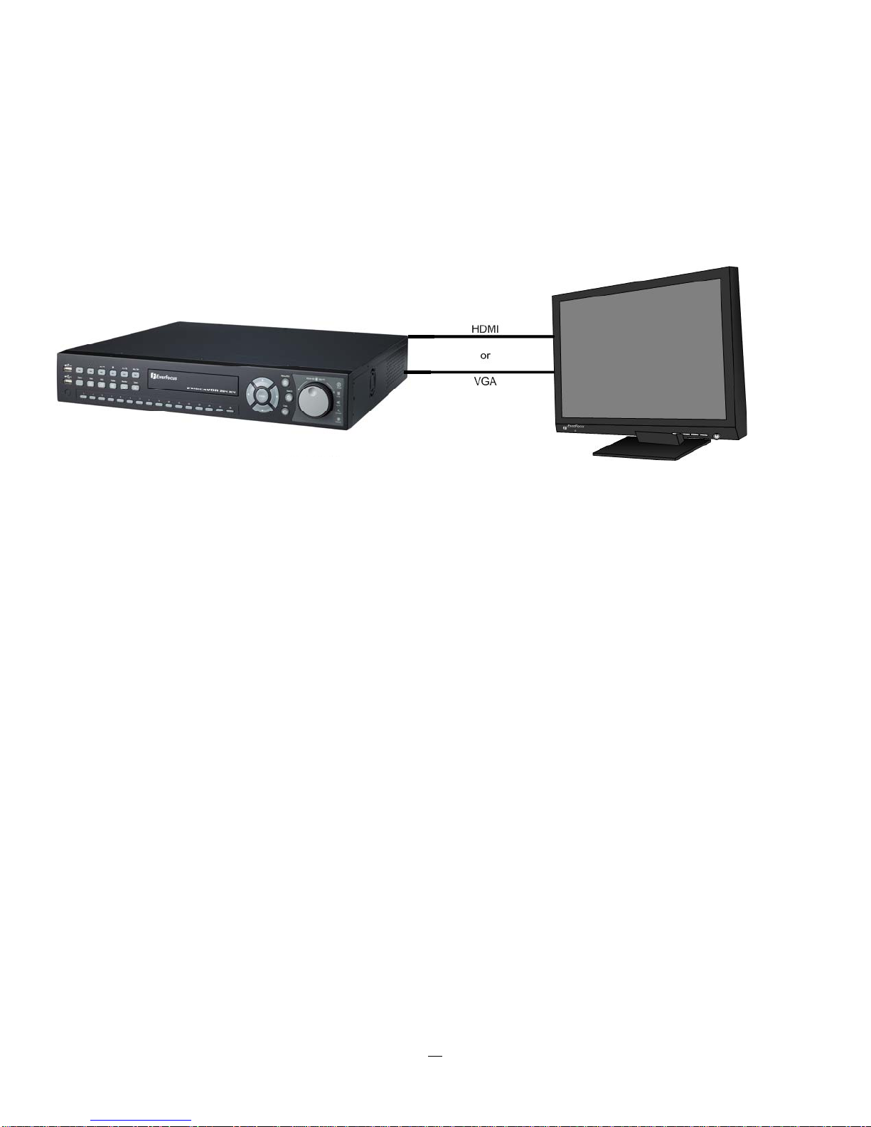
1.6 MONITOR INSTALLATION
The ENDEAVOR DVR provides 2 main monitor outputs with identical functionality - VGA and HDMI.
Both outputs can be used simultaneously and deliver full HD output resolution (1920x1080, progressive, 60
Hz. vert., 68 KHz hor.).
Make sure that the connected monitor's specifications comply with these resolution requirements.
Please do not exceed the max. HDMI cable length of 15 m.
For cable length up to 3 m standard HDMI cables mostly work well, for longer distances (especially in the
15m range) please use only high quality HDMI cable.
1.7 AUDIO INSTALLATION
This DVR provides 4 line level audio inputs and 1 line level audio output.
ATTENTION: The direct connection of a non-amplified microphone is not supported (a microphone
amplifier is required). The audio output requires an amplifier to drive a speaker or headphones.
The installation must be connected with audio coax cable and RCA plugs.
AUDIO RECORDING FUNCTIONALITY:
Audio recording is activated / deactivated in the Camera Menu for Camera #1~4 respectively. Please check
and always comply with local laws and regulations when using audio recording.
The audio channel is always recorded together with video and is independent of the image recording rate.
Though the audio record control is done in the Camera #1~4 screen, there is no specific camera allocation.
11

1.8 ALARM CONT A CTS INSTALLATION
The alarm inputs can be used to start recording or for recording rate adjustment. In addition, alarm
reactions such as camera display on the monitor, buzzer, e-mail and network alarm are available. The
alarm output relay can be switched if required. Alarm input response actions can be controlled according to
a flexible schedule.
1.8.1 Alarm Input Contacts
This DVR provides one alarm input per camera. All inputs are programmable N.O. (Normal Open) or N.C.
(Normal Closed) Inputs have to be switched by dry contacts.
Alarm input with N.O. (Normal Open) contact Alarm input with N.C. (Normal Closed) contact
in idle state in idle state
All settings are programmed in the ALARM menu (Section 0).
1.8.2 Alarm Output Relay
The relay output provides either Normally Open or Normally Closed dry contacts.
Output relay in idle state
1.9 RS-485 keyboard / PTZ Installation
All functions can be remote-controlled by the EKB-500 universal keyboard. Using the EEPbus protocol,
digital video recorders, keyboards and speed domes can be installed on one single RS-485 bus. One
system can comprise up to 8 keyboards.
1.9.1 General RS-485 bus installation
The EKB-50
CAT5 network cable is recommended, UTP version (unshielded) is sufficient for normal applications. A
shielded cable should be used if the installed cables are expected to be highly susceptible to interference.
The number of devices installed in one bus is limited to 32, and the maximum cable length is 3,900 feet.
Both of these can be expanded using a signal distributor EverFocus Model EDA997A (see below).
0 keyboard uses a RS-485 simplex wiring; the signal is transferred via a single twisted pair line.
12
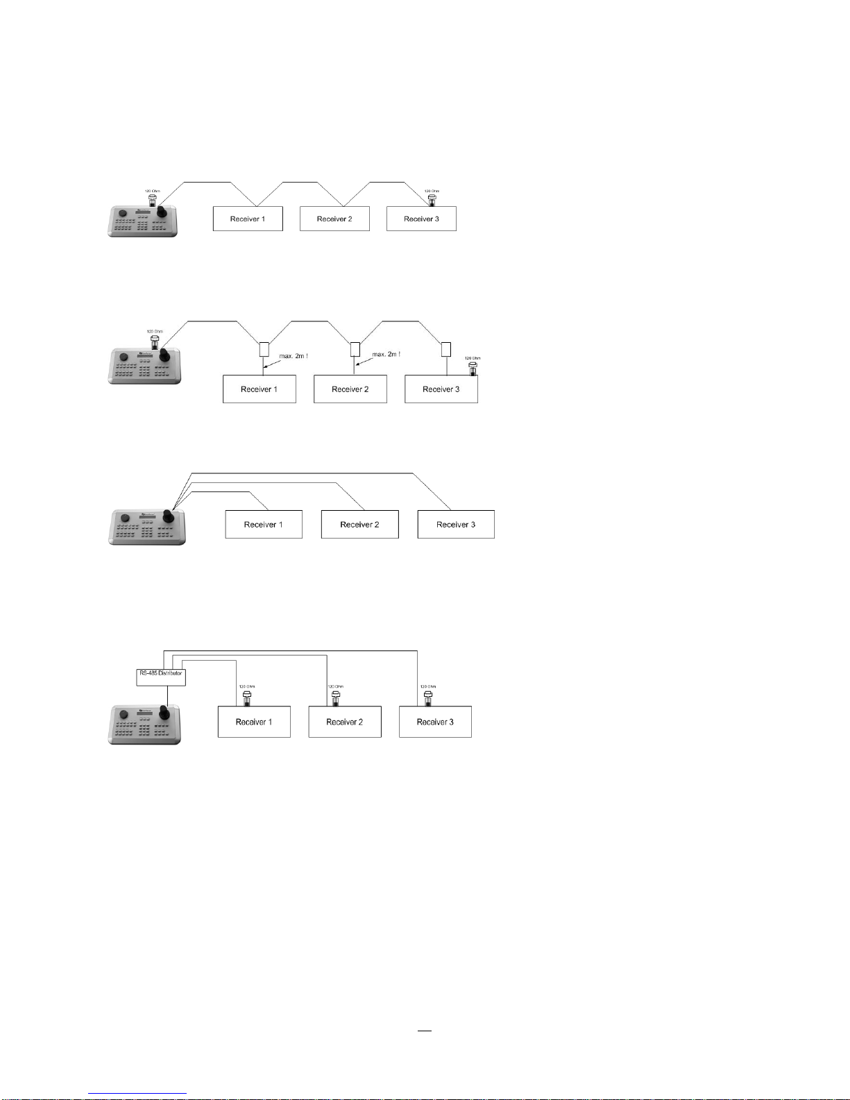
Both the first and the last device in series should be terminated with 120 Ohm resistance in order to
minimize line reflections.
RS-485 bus serial wiring
Cable length from box to device („Stubs“) has to be limited to 2m using connector boxes.
RS-485 bus serial wiring with connector boxes and connection cable
Direct RS-485 bus star wiring is not supported unless using an EverFocus Model EDA997A (see below).
Improper RS-485 bus star wiring
An EDA997A RS-485 signal distributor may be used to use a star wiring configuration.
Star wiring with RS-485 signal distributor
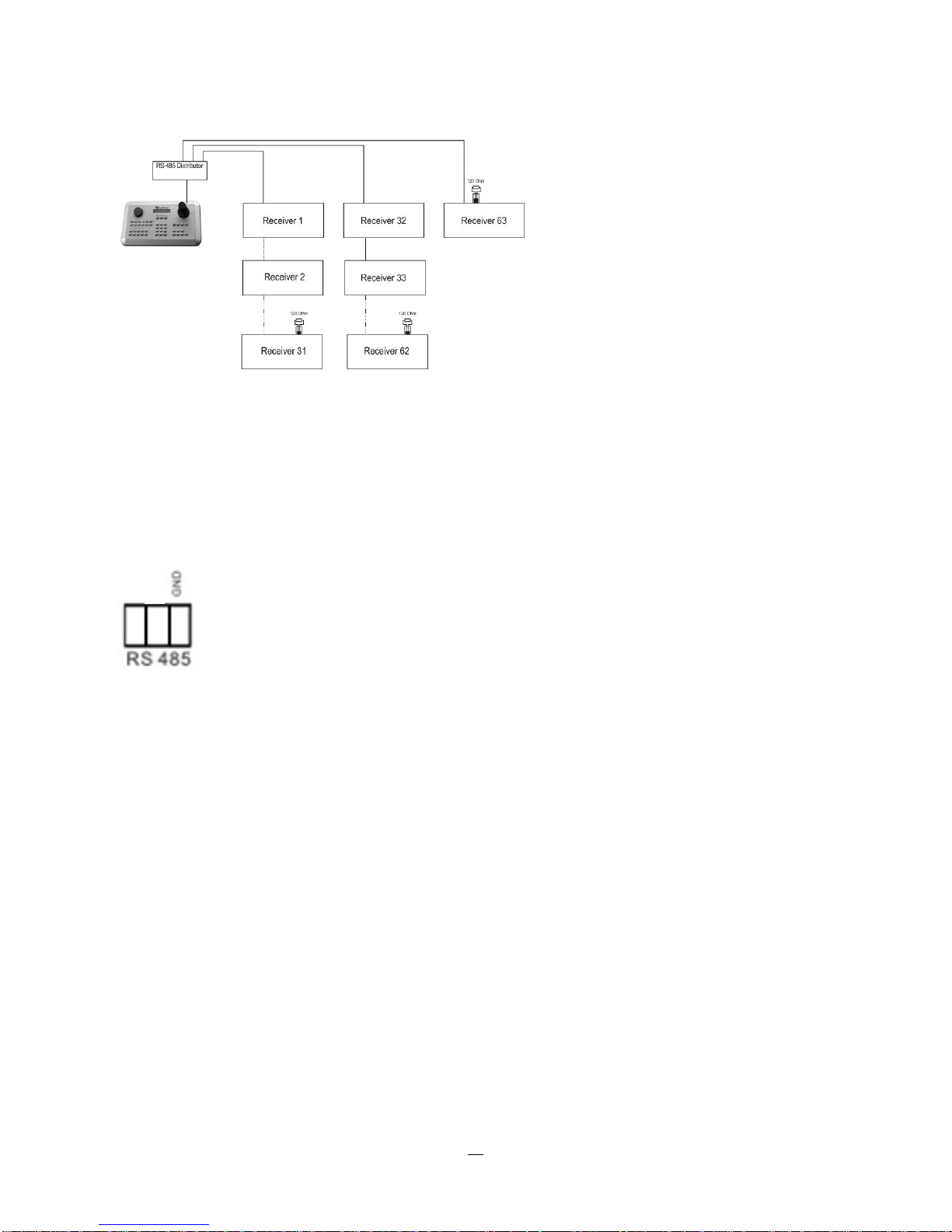
A RS-485 distributor can also be used to increase the maximum number of devices on the bus as well as
the total range. Each distributor output provides another RS-485 bus. This allows each output to extend an
additional 1200m, and it also enables the additional connection of 31 further devices to each output (the
output itself represents one device).
The maximum system expandability depends on the RS-485 address range of the installed devices.
13
System expansion with RS-485 signal distributor
ATTENTION: EDA997A signal distributors are unidirectional! This means that the signal only flows from
the input towards the outputs. Therefore, e.g. the interconnection of several keyboards is not possible with
these types of signal distributor!
1.9.2 RS-485 socket pin assignment
The RS485 pin assignment is as follows:
+
I
1.9.3 EKB-500 connection with network patch cable
For a simple, short distance installation, recorder and keyboard can be connected directly using a standard
CAT5 network cable with an 8-pin connector at only one end, and at the other end the Pin 3 wire connected
to RS485 “+” (plus) and the pin 6 wire connected to RS-485 “-“ (minus).
1.9.4 EKB-500 connection to several DVRs
For long distance installations connecting several DVRs, please use an EDA997A signal distributor to
connect. For further details on keyboard connection, please refer to the EKB-500 manual.
RS-485 port communication settings are configured in the I/O CONTROL menu (Section 5.10.4 System
Setup: I/O
- control).
1.9.5 Speed Dome Installation
Speed dome or telemetry receiver pan/tilt/zoom control is available through web browser or the optional
PowerCon software if the DVR is connected to a network. Local telemetry control is provided by USB mouse control or by the optional EKB-500 keyboard.
Supported protocols: EverFocus, Pelco-D, Pelco-P, Samsung, Transparent
14
Required DVR settings: RS-485 receiver address in CAMERA menu
(Section 4.3)
RS-485 parameters and protocol in the I/O CONTROL menu
(Section 5.10.4)
ATTENTION: Some Pelco-
D / -P protocol domes and receivers require an address offset of -1, i.e. the
address assigned to the dome / receiver in the DVR camera menu must be 1 below the address set in the
dome / receiver itself!
1.10 USB-Mouse installation
Connect the USB mouse to one of the 2 USB ports. (This can be done while DVR is powered on) The rear
USB V1.0 port is recommended to reserve the higher speed front USB V2.0 port for video copy/export.
NOTE: Recommended mouse types are Logitech® and Microsoft® wired USB wheel-mouse. Wireless
USB mouse is not supported.
1.11 NETWORK CONNECTION
This section only describes physical connection to an Ethernet network. This step must be completed
before the DVR can connect to the network. There are two basic types of connection:
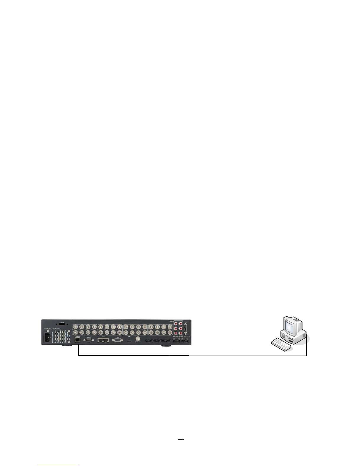
1.11.1 Direct PC Connection through Crossover Network Cable
The point-to-point connection of DVR and PC requires a crossover (crossed) network cable. This type of
connection is ONLY used for direct connection to a single PC. Make sure that the PC is equipped with a
10/100Mbps compatible network connection.
Figure 1-3 Direct PC Connection
15
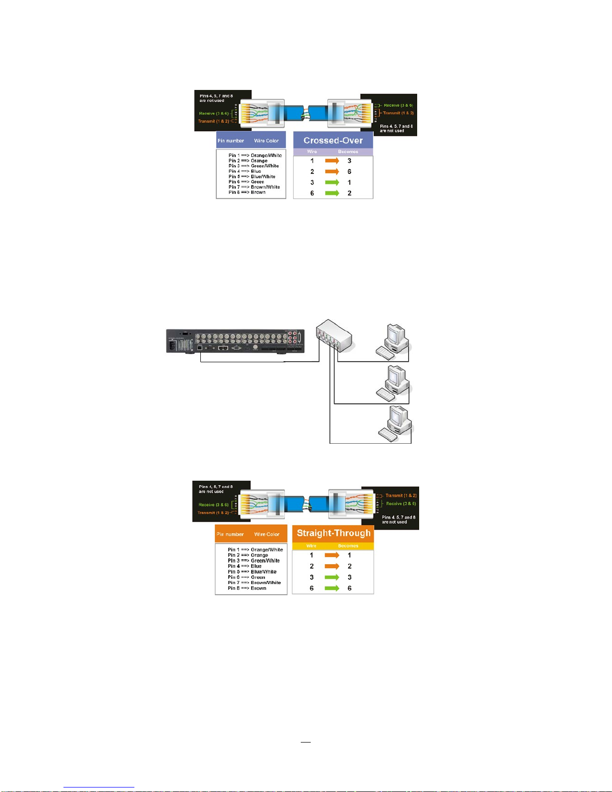
Pinout of crossover-cable
1.11.2 Network Connection through Patch Cable
The connection to an existing network requires a normal patch cable (straight-through). Th
shows the connection to a network switch or router.
Figure 1-4 Network Connection through Patch Cable
e illustration
Pinout of straight patch cable
16

1.12 FINAL INSTALL PROCESS
Once you have completed the basic wiring connections, you are ready to turn on the DVR. Simply plug in
the power source. The POWER LED will light up if power is normal. Once the system has finished loading,
you can begin to set up the menu options for the DVR.
17

Chapter
3
2 MOUSE AND FRONT P ANEL OPERATION
ENDEAVOR DVRs support multiple sources to control the DVR. It can be controlled with a mouse, the front
panel, an EKB500, and the handheld IR remote control.
This chapter will cover the basic operation using the mouse and the front panel buttons.
2.1 GENERAL USB MOUSE OPERA TION
2.1.1 How to select a channel / Enable audio
1. In a view consisting of more than one channel, users can select a channel by clicking once on the
desired channel screen. The selected screen will be highlighted by a white frame.
2. Double clicking on a channel screen will display full screen for this channel.
3. To enable audio out, click the audio icon (ex: ) at lower side of the screen. This system has only
one audio out. Click this button to enable or disable the audio-out mode.
2.1.2 OSD Root Menu
1. Right-click the mouse to obtain the DVR menu bar (see Figure 2-1 OSD Root Menu ). When you move
the mouse over each icon, its title will be displayed at the top of the control bar.
Figure 2-1 OSD Root Menu
2. Click on any icon to perform that action. These actions are covered in detail in Chapter 3.
3. Click the “X” in the top-right corner to close the DVR control bar.
18
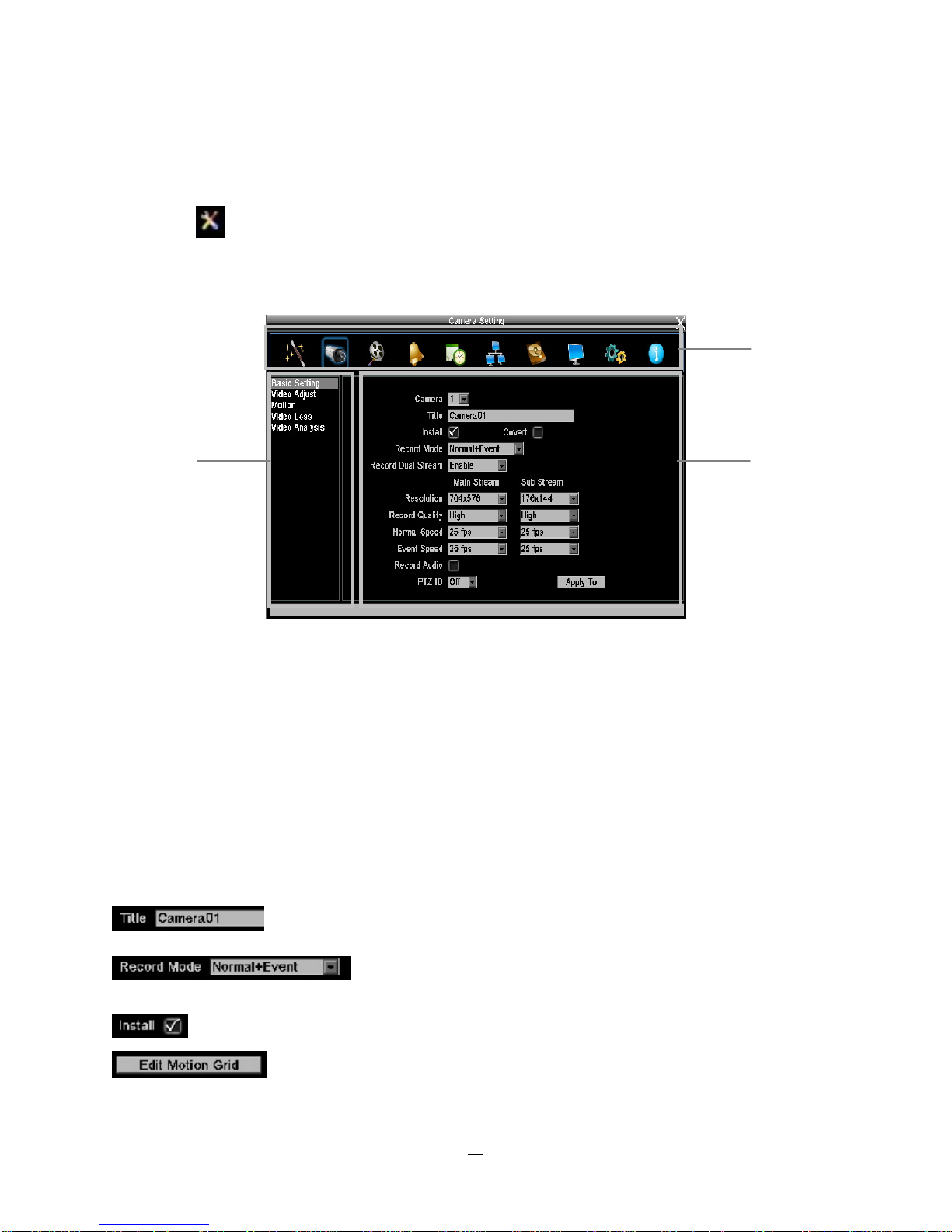
2.1.3 Operation in the Configuration Menus
Click on the
icon to access the Configuration Menu.
The Configuration menu screens (shown in Figure 2-2 OSD Menu) are divided into 3 main sections.
1
2
3
Figure 2-2 OSD Menu
1. In section 1, there are ten setup options available. Move the mouse over an icon and click to select it.
2. In section 2, the choices for the selected icon will be displayed. Click on a choice to select it.
3. In section 3, all the options for the selected choice will be available. Click on a field to make changes.
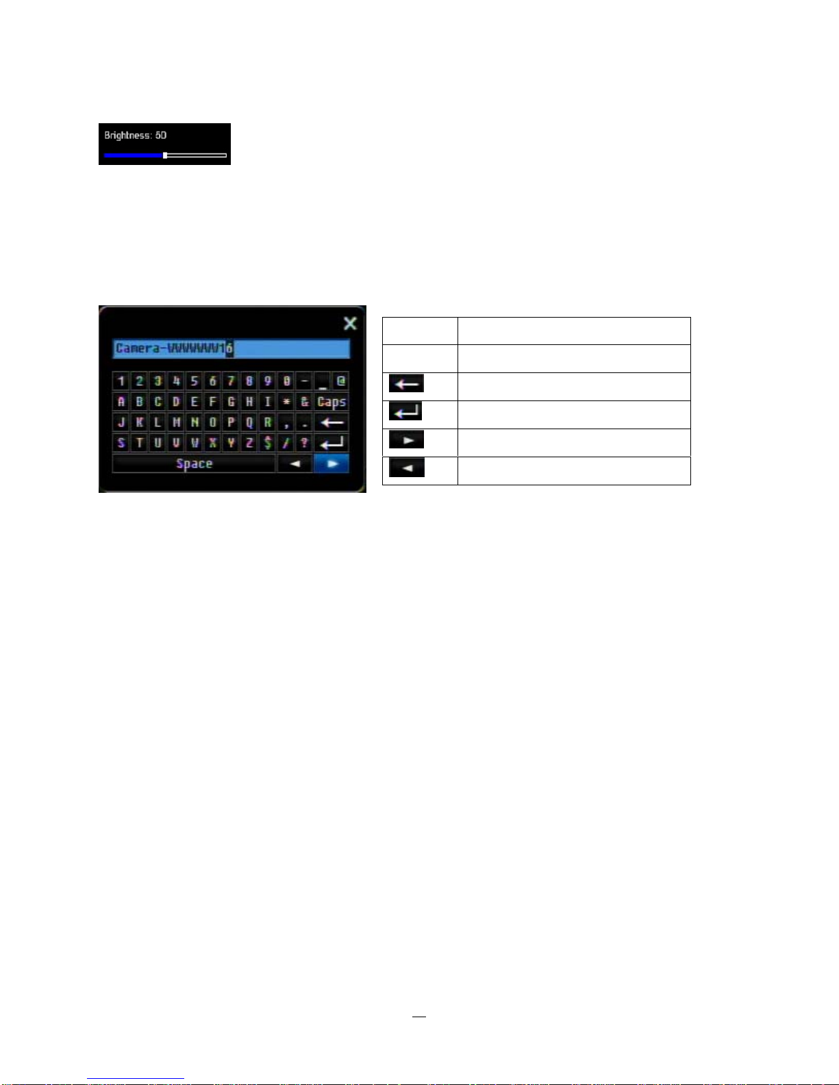
2.1.4 Field Input Opt
The following are examples of different types of fields available in the Configuration menu.
Textbox: Click on the box and an on-screen keyboard will appear*. (see note about
the on-screen keyboard below)
directly click on an option to select it.
Check box: Click on the box to enable it (checked) or disable it (unchecked).
Button: Click the button to execute the function.
ions
Dropdown box: Click on the down arrow to see all selections, then
19
Bar: Click and hold on the bar to adjust the set point Left or Right.
* Note about on-screen keyboard:
Click on a button to input that character.
The buttons on the right and bottom have the following functions:
Space Enter a space
Caps Switch to capital letters
Delete the letter
Confirm the selection
Move to right
Move to left
20
2.2 General Front Panel Operation
2.2.1 How to select a channel / Enable audio
1. In a view consisting of more than one channel, press the arrow keys (Up/Down/
Right/Left) to scroll
through each channel that is displayed. The selected channel will be highlighted by white frame.
Pressing the “left” or “right” arrow when the last/first camera (1,4, 9 or 16) is highlighted will select all
cameras.
2. While channel #1 is selected, press the “Enter” button to turn Audio On/ Off.
2.2.2 OSD Root Menu
1. Press “Me
nu” key to display the DVR menu bar. Use the left/right arrows to scroll over each icon. The
title for each icon will be displayed on top of the menu bar.
2. Press “Enter” key on any icon to perform that action. These actions are covered in detail in Chapter 3
3. Press “Menu” to close the DVR menu bar.
2.2.3 Front Panel Key Review
The basic principle of front panel operation is to use arrow keys to navigate among the menu items. Use
the “Enter” key to confirm a selection or enter the next level menu. Press the “Menu” key to enter the Main
Menu or exit from the current level of the menu.
2.2.4 Operation in Configuration Menu
Press “Menu”, use the arrow keys to highlight the “Configuration” icon, and press “Enter” with
“Configuration” icon highlighted to bring up the Configuration menu.
NOTE: If the require password option is active, you will need to log in first. Refer to “Section 3.2 LOGIN” for
information on logging in. The menu (shown in Figure 2-3 OSD Menu ) is divided into 3 main sections.
21
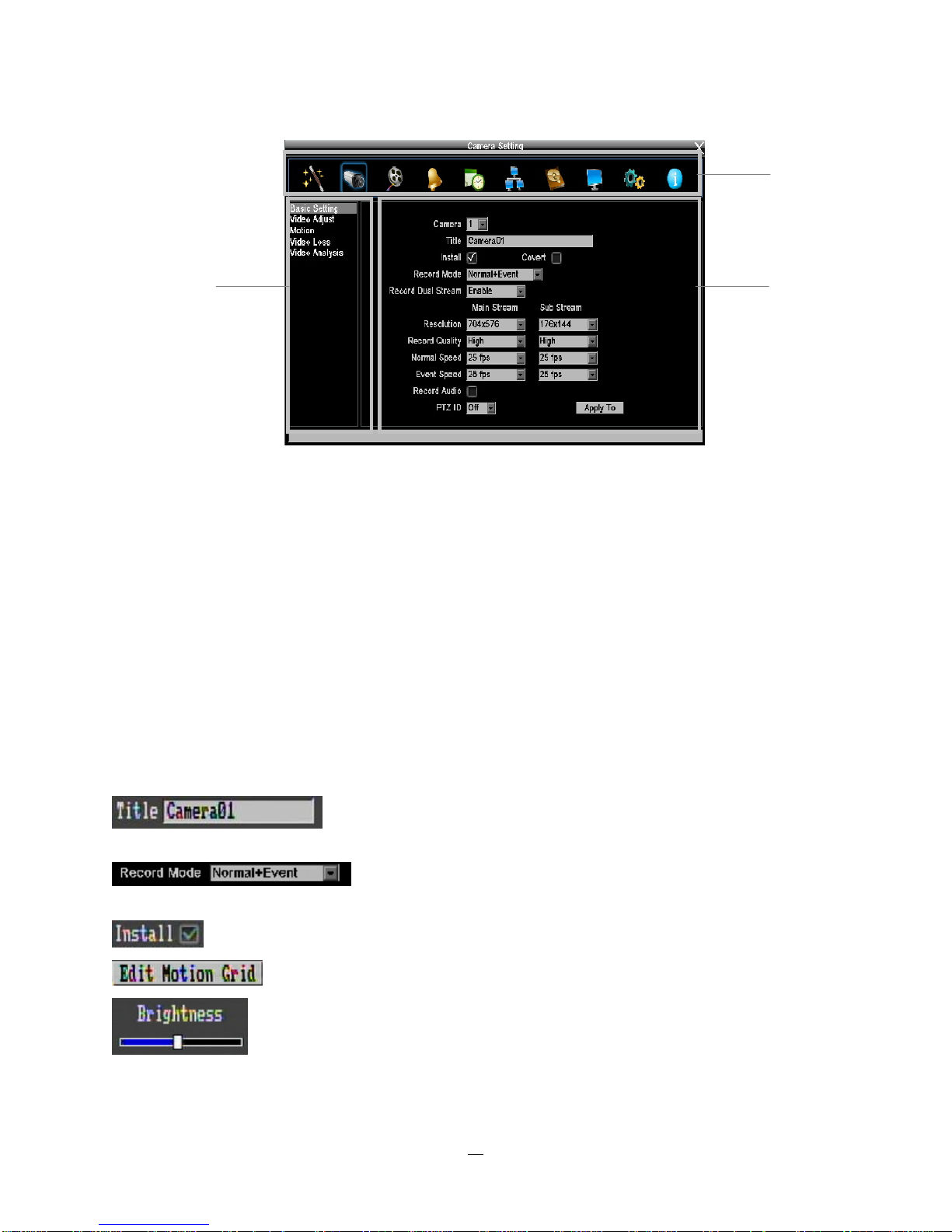
1
2
3
Figure 2-3 OSD Menu
1. In section 1, there are ten setup options available. Use arrow keys to highlight an icon and press “Enter”
to select it.
2. In section 2, the main choices for the selected icon will be displayed. Use Up/Down arrow keys to
highlight a choice and press “Enter” to select it.
3. In section 3, all the options for the selected choice will be available here. Use arrow keys to move
between items and press “Enter” to make changes to that item.
Note: press the “Menu” button to go back to the previous menu section/level.
2.2.5 Field Input Options
note about on-screen keyboard below)
arrow keys to highlight the desired option and press “Enter” again to select it.
Check box: Press “Enter” key on a setting to enable it (checked) or disable it (unchecked).
Button: Press “Enter” key to execute the function.
Bar: Press “Enter” key to activate the slider, then use arrow keys to adjust the setting.
Press “Enter” again to finalize the changes.
Textbox: Press Enter key and an on-screen keyboard will appear*. (see
Dropdown box: Press “Enter” key to show the available options. Use
22
 Loading...