

Page 1
Indoor Outdoor
EFN Series Fisheye Network Camera
3MP 360 ePanoramic View, IP68, IK10
Quick Installation Guide
Copyright © EverFocus Electronics Corp,
Release Date: August, 2014
Page 2
EFN Series Fisheye IP Camera
2
1
3
Rear View
Front View
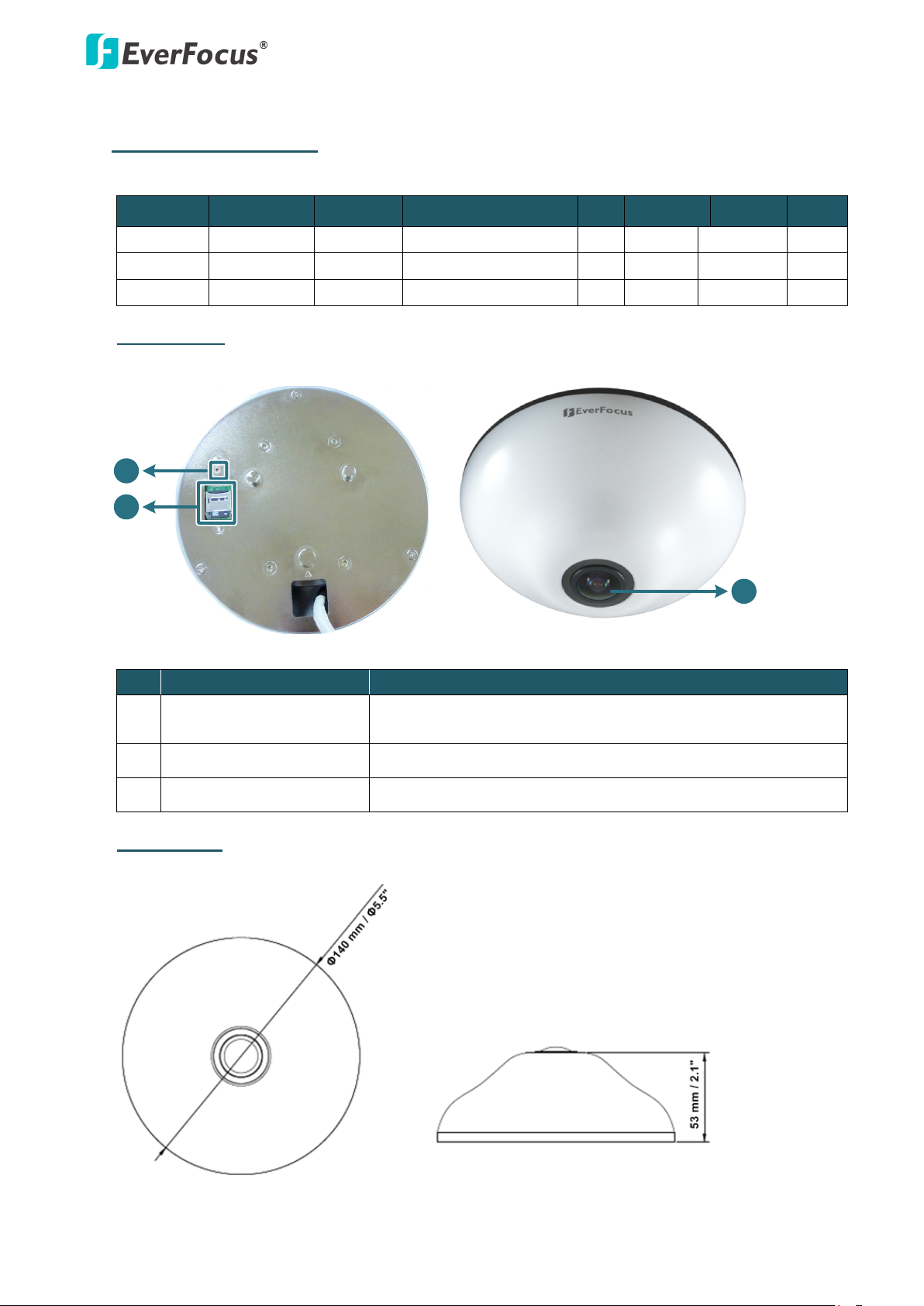
1. Physical Description
The EFN Series is designed for indoor and outdoor use. The series comes in three models:
Model Megapixel Type Protection Rating PoE 12 VDC Audio I/O
EFN3320 3 MP Indoor - Yes - - EFN3320
EFN3321 3 MP Outdoor IP68, IK10 Yes Yes Yes Yes
Indoor Type
3 MP Indoor - Yes Yes Yes Yes
No. Item Name Descriptions
1 Reset Button
Press the button for 7 seconds to reset all configurations to
the factory default settings.
2 Micro SDHC / SDXC Slot For inserting a micro SDHC / SDXC card.
3 Fisheye Lens Fisheye lens with fixed IRIS and IR corrected.
Dimensions
1
Page 3
2
4
1
52
6
3
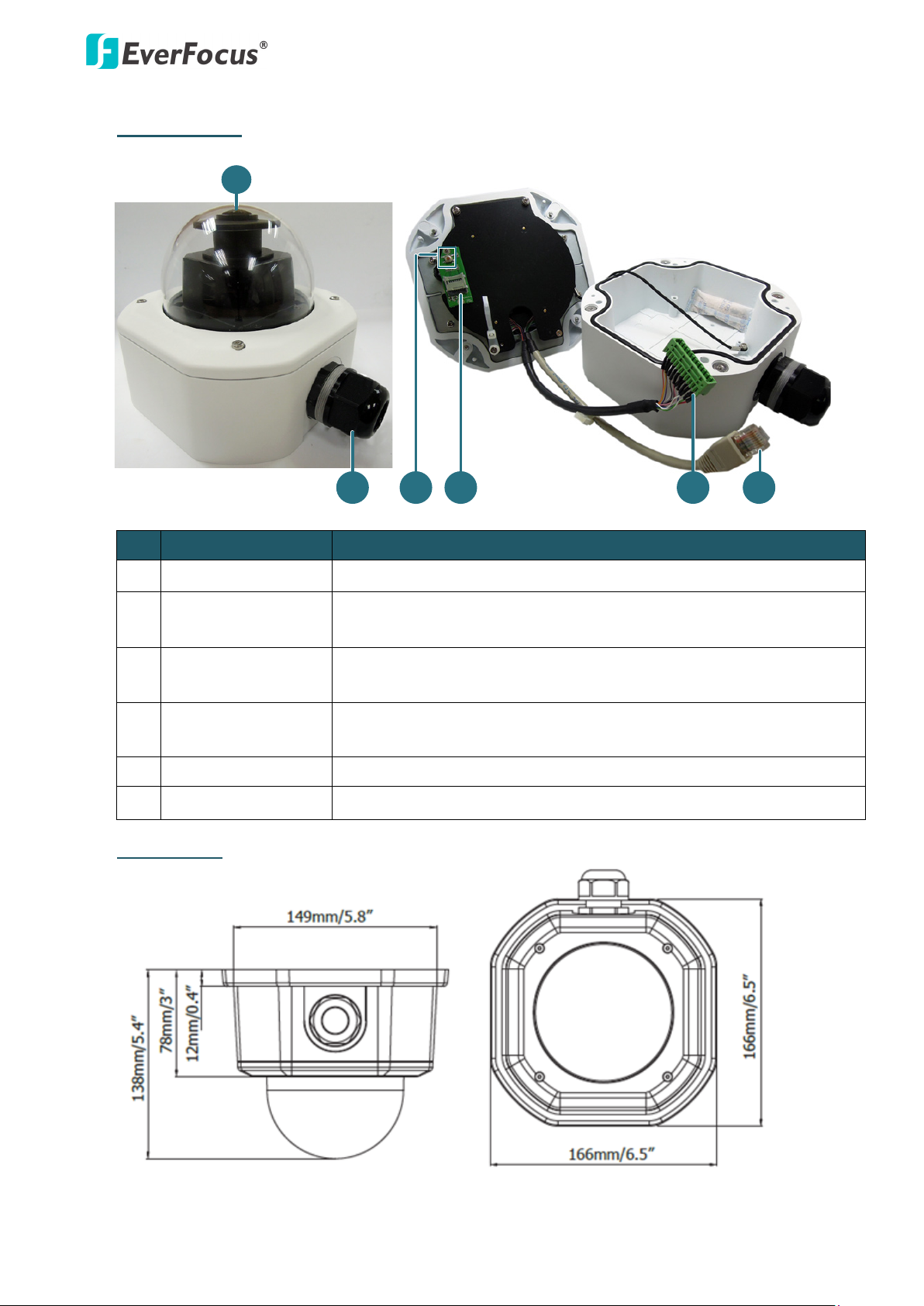
Outdoor Type
EFN Series Fisheye IP Camera
No
Item Name Descriptions
1 Lens Fisheye lens with fixed IRIS and IR corrected.
2 Cable Gland Equipped with three plugs inserted in the cable conduits for
waterproofing.
3 Reset Button Resets all configurations to the factory default settings. Press and
hold the Reset Button for 10 seconds by using a pen or a paper click.
4 Micro SDHC / SDXC
Insert a micro SDHC / SDXC card.
Slot
5 Terminal Block A 12-pin terminal block. See 2.Cables and Terminal Block below.
6 LAN / PoE Port Connects to a 10/100 Ethernet or PoE.
Dimensions
Page 4
EFN Series Fisheye IP Camera
3
Minimum System Requirement
Before installing, please check that your computer meets these system requirements.
• Operating System: Microsoft Windows XP / Vista (32-bit) / 7 (32-bit)
• Microsoft Internet Explorer 7 or above
Packing List
Please check that there is no missing item in the package before installing.
Indoor Type
• Camera x 1 • Screw x 3 (with 3 Anchors)
• RJ-45 Connector x 1 • Spacer x 1
• Mounting Template x 1 • Software CD x 1
• Tilting Wall Mount Bracket (15° tilt angle) x 1 • Quick Installation Guide x 1
Outdoor Type
• Camera x 1 • Desiccant Bag x 2
• Base Plate Screw x 4 • Inner Paper x 1
• Screw Anchor x 4 • Software CD x 1
• Hexagon Screwdriver x 1 • Quick Installation Guide x 1
Note:
1. Equipment configurations and supplied accessories vary by country. Please consult
your local EverFocus office or agents for more information. Please also keep the
shipping carton for possible future use.
2. Contact the shipper if any items appear to have been damaged in the shipping
process.
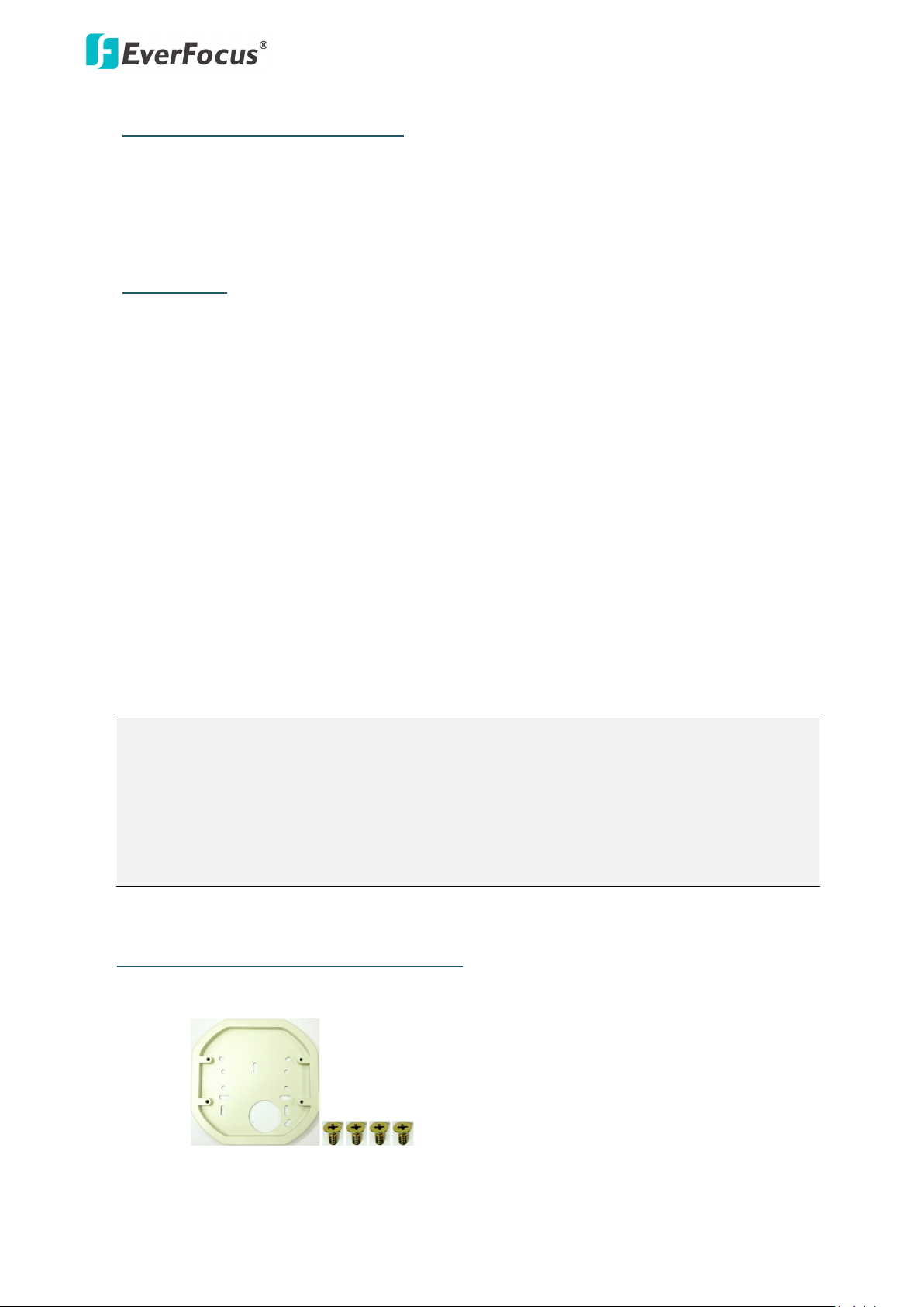
Optional Accessory (for Outdoor Type)
One Adapter Plate with 4 Screws
The Adapter Plate is designed for installing the
camera to the wiring box on the wall. Please
refer to Step 3.d in 3.3 Outdoor Type for more
details.
Page 5
EFN Series Fisheye IP Camera
4
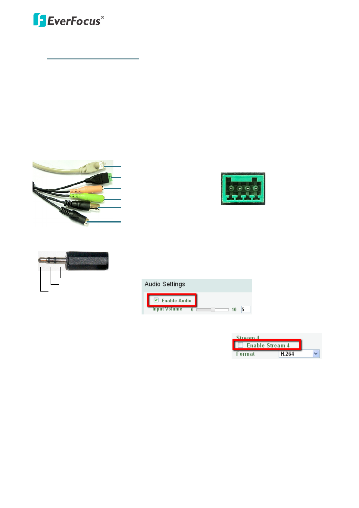
Alarm Input / Output
Audio Input (TRS Line-in)(Pink)
Audio Output (TRS Line-out)(Green)
Video Test-Out (BNC)
12 VDC Input
LAN / PoE Cable
4 3 2 1
Pin Assignment from Alarm I/O
Pin 1: Alarm In (+)
Pin 2: Alarm GND (-)
Pin 3: Alarm COM (-)
Pin 3: Alarm Out (+)
TRS Connector
Left Channel (Tip)
Right Channel (Ring)
Ground (Sleeve)
2. Cables and Terminal Block
This section describes the cables and terminal block of the fisheye cameras. The EFN3320 only
features a PoE cable.
For EFN3320c (Indoor)
The Cables provide connections for Network, power, audio input / output, alarm input / output and
video test output. Note that the audio line in/out cable features a 3.5mm TRS connector. Be sure to
prepare speakers / microphones with TRS connector (see TRS Connector image below). Also,
speakers / microphones with a (built-in) amplifier and external power supply are required.
To activate the Audio function, the Enable Audio must be checked.
See Audio Settings in 7.2.1 Streaming and Audio in the User’s
Manual.
For the Video Test-Out cable to work, the Stream 4 must be
disabled (unchecked), see Stream Settings in 7.2.1 Streaming
and Audio in the User’s Manual.
Page 6
EFN Series Fisheye IP Camera
5
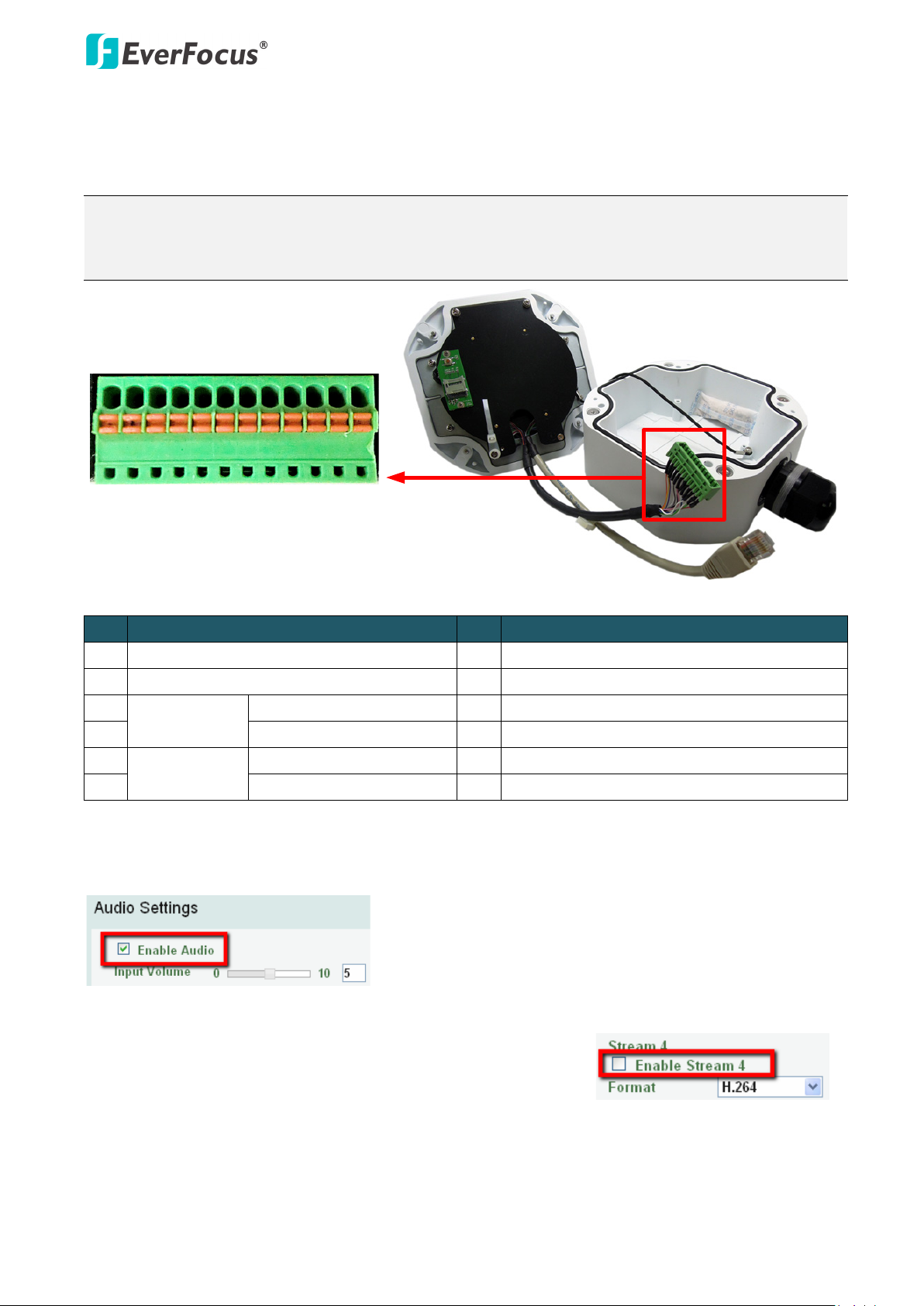
1 2 3
4 5 6 7 8 9
10 11 12
Camera Module
For EFN3321 (Outdoor)
The I/O terminal block, located on the camera module, can be used to develop applications for
alarm input and output, two-way audio, TV-output or a variety of other functions.
Note:
1. You can unplug the terminal block from the camera module for easier wiring.
2. Microphones / speakers with an (built-in) amplifier and external power supply are required.
No. Functions No. Functions
1 12 VDC Input 7 Audio Input C (TRS Line-in)
2 Digital GND 8 Audio GND
3
Alarm Out
Alarm Output C (+) 9 Audio Output (TRS Line-Out)
4 Alarm COM C (-) 10 Audio GND
5
Alarm In
Alarm Input C (+) 11 CVBS Output
6 Digital GND (-) 12 Digital GND
To activate the Audio function, the Enable Audio must be checked. See Audio Settings in 7.2.1
Streaming and Audio in the User’s Manual.
For the Video Test-Out cable to work, the Stream 4 must be
disabled (unchecked), see Stream Settings in 7.2.1 Streaming
and Audio in the User’s Manual.
Page 7
EFN Series Fisheye IP Camera
6
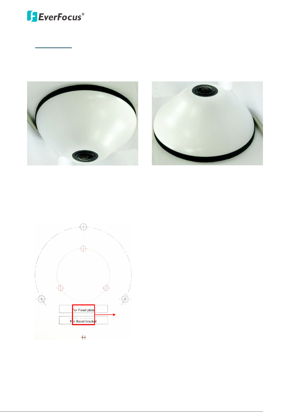
Ceiling Mount Desk Mount
For the Tilting Wall Mount Bracket
Drill a hole only if you want to run
the cables through the ceiling / desk.
3. Installation
3.1 Indoor Type – Ceiling / Desk Mount
1. Stick the Mounting Template to the ceiling / desk. Drill the three red cross marks on the inner
circle, and the square below only if you wish to run the cables through the ceiling / desk. Note
that the square below also indicates the cable position. Point the square below to the direction
for running the cables.
Page 8
EFN Series Fisheye IP Camera
7
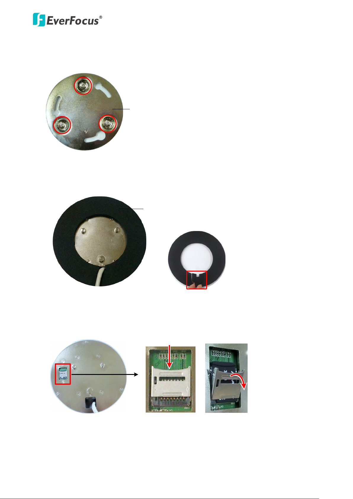
Base Plate
Spacer
Push
Pull
Rear side of the camera
2. Insert the supplied three Anchors into the three holes and then screw the Base Plate to the
ceiling / desk using the supplied three Screws.
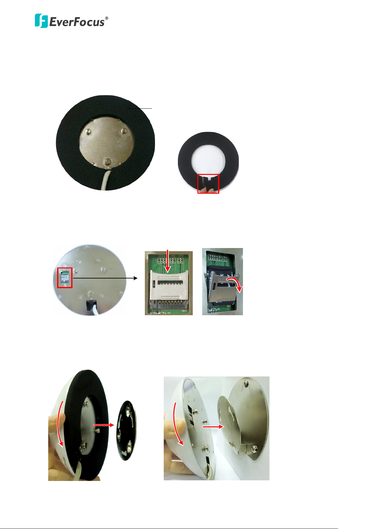
3. Place the Spacer onto the rear side of the camera. Remove the cut-out from the Spacer only if
you want to run the cables along the ceiling / desk.
4. Optionally insert the micro SDHC / SDXC card to the push-pull type SD card slot on the rear side
of the camera.
Page 9

EFN Series Fisheye IP Camera
8
Rear side of the camera
Base Plate
With the Tilting Wall Mount Bracket
With the Base Plate
5. Align the three latches on the camera with the three holes on the Base Plate, attach the camera
to the Base Plate and then rotate clockwise to secure the camera to the Base Plate. Note that
the triangle mark on the rear side of the camera and the Base Plate should point to the same
direction.
6. Connect the network or power cable to the camera. The installation is now complete.
3.2 Indoor Type-Wall Mount
You can mount the camera to the wall using the supplied Base Plate or the Tilting Wall Mount
Bracket.
Page 10

EFN Series Fisheye IP Camera
9
Drill a hole only if you want to
run the cables through the wall.
Toward the ground
For the Tilting Wall Mount Bracket
Base Plate
Tilting Wall Mount Bracket
1. Stick the Mounting Template to the wall. Drill the three red cross marks on the inner circle. If
you want to use the supplied Tilting Wall Mount Bracket, drill the three black cross marks on
the outer circle. Drill the square below only if you wish to run the cables through the wall. Note
that the square below also indicates the cable position. Point the square below to the direction
for running the cables.
2. Insert the supplied three Anchors into the three holes and then screw the Base Plate / Tilting
Wall Mount Bracket to the wall using the supplied three Screws.
Page 11
EFN Series Fisheye IP Camera
10
Spacer
Push
Pull
Rear side of the camera
With Base Plate With Tilting Wall Mount Bracket
3. If you are using the Base Plate, place the Spacer onto the rear side of the camera. This step is
only for the Base Plate mounting. Remove the cut-out from the Spacer only if you want to run
the cables along the wall.
4. Optionally insert the micro SDHC / SDXC card to the push-pull type SD card slot on the rear side
of the camera.
5. Align the three latches on the camera with the three holes on the Base Plate / Tilting Wall
Mount Bracket, attach the camera to the Base Plate / Tilting Wall Mount Bracket and then
rotate clockwise to secure the camera to the Base Plate / Tilting Wall Mount Bracket.
Page 12

EFN Series Fisheye IP Camera
11
Rear side of the camera
Base Plate
Tilting Wall Mount Bracket
Note that the triangle mark on the rear side of the camera should point to the same direction
with the triangle mark on the Base Plate / Tilting Wall Mount Bracket.
6. Connect the network or power cable to the camera. The installation is now complete.
3.3 Outdoor Type
The following instruction is an example of Wall Mount installation. You can apply this instruction to
Ceiling / Desk Mount as well.
Ceiling Mount Desk Mount Wall Mount
1. Unscrew the four screws and remove the cover from the camera.
Page 13

EFN Series Fisheye IP Camera
12
Camera Case
Base Plate
Base Plate
Wiring Box
Wall
Circle Plate
Camera Case
2. Unscrew the four screws and remove the Base Plate from the Camera Case.
3. Screw the Base Plate to the ceiling / wall / desk using the supplied four screws.
If you want to wire the cables through the bottom of the Camera Case, follow the steps
below:
a. Remove the Circle Plate on the bottom of the Camera Case. You can simply loosen the Circle
Plate using a coin.
Page 14

EFN Series Fisheye IP Camera
13
Cable Gland
Camera Case
Base Plate
Wall
Base Plate Wiring BoxAdapter Plate
b. Loosen and remove the Cable Gland from the Camera Case. Screw the Cable Gland to the
hole on the bottom of the Camera Case.
c. Screw the Circle Plate to the side hole on the camera Case.
d. Screw the Base Plate to the ceiling / wall / desk.
If you want to install the camera to a wiring box, you have to screw the Adapter Plate
between the Base Plate and the Wiring Box.
Page 15
EFN Series Fisheye IP Camera
14
Base Plate
Camera Case
Screw Body
Screw Cap
Stopper Claw
Plug
Stopper
Adjustment Ring(s)
Cable Gland Cable Gland
Screw Cap
Plug Stopper
Cable Conduit
4. Screw the Camera Case back to the Base Plate.
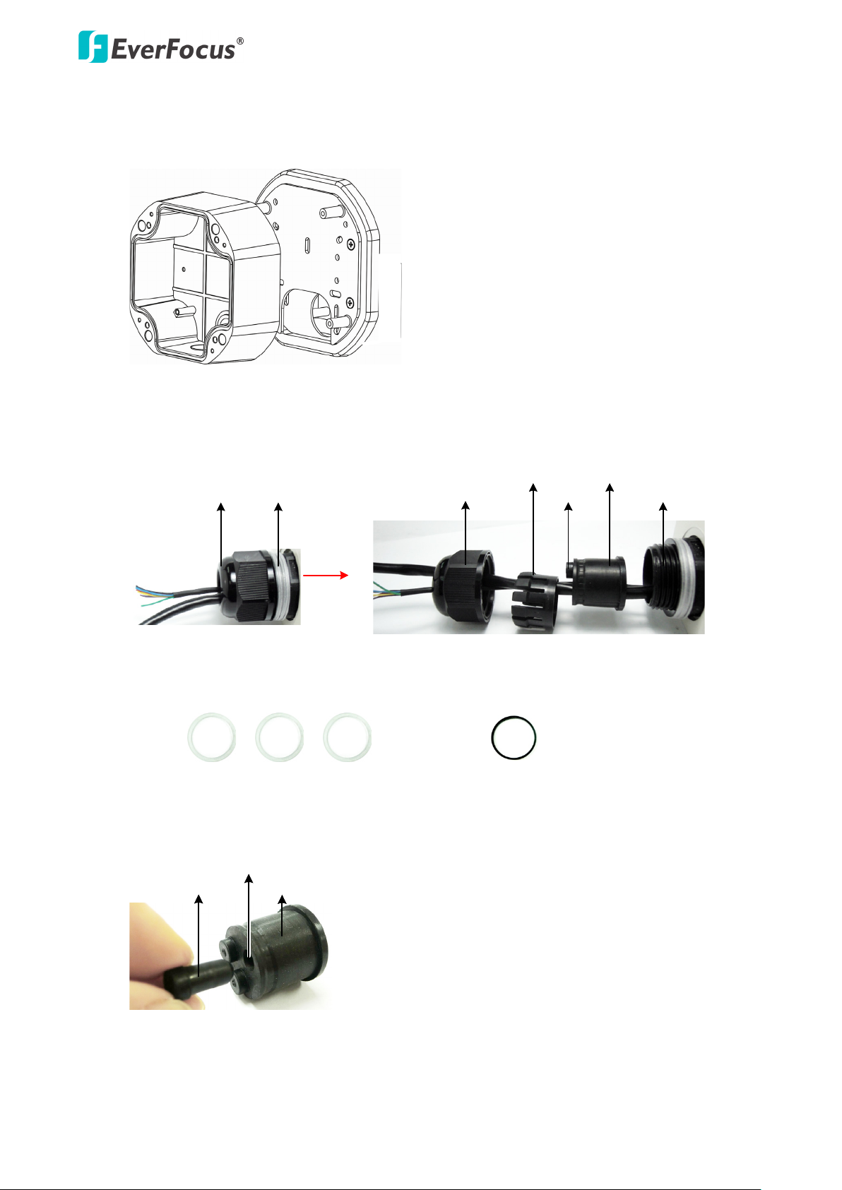
5. Insert the PoE cable or the additional cables through the Cable Gland. Up to three cables can be
inserted. Note that except the PoE cable, additional wires have to be bundled into a cable with
diameter ranging from 5.3mm to 6.4mm (see Step d below).
a. Keep the supplied 6 Adjustment Rings for waterproofing.
b. Remove the Plug(s) from the Stopper (depends on the number of cables inserted). One
• Transparent x 5 (1 mm thickness)
• Black x 1 (0.5 mm thickness)
Cable Conduit can only be inserted with one cable.
Page 16

EFN Series Fisheye IP Camera
15
Slitted Cable Conduit
c. Insert the PoE cable through the Cable Conduit, if your PoE cable already has a RJ-45
connector, then you can use the Slitted Cable Conduit.
d. Optionally insert the additional wires, such as power (if you want to power the camera
through a 12 VDC power source), alarm and audio cables, through the other Cable Conduit.
Note that one Cable Conduit can only be inserted with one cable. The Cable Conduit has
been tested to support cable diameter between 5.3mm and 6.4mm. Please refer to the
image below to bundle the lose wires before inserting to the Cable Conduit.
e. Tighten the Screw Cap all the way to the Adjustment Ring(s).
f. Due to the variable cable diameters, for better waterproofing, it is strongly recommended
that you apply silicon sealants to the inner Screw Cap.
6. Connect the PoE cable to the LAN / PoE port on the camera module.
7. If you have inserted additional wires, connect the wires to the terminal block. Please refer to 2.
Cables and Terminal Block for pin assignment.
Page 17

EFN Series Fisheye IP Camera
16
8. Optionally insert a micro SDHC / SDHC card to the card slot.
9. Stick the supplied 2 desiccant bags inside the camera case.
Note: It is highly recommended to replace the desiccant bags every time when you open
the camera.
10. Place and screw the camera module back to the camera case.
Page 18
EFN Series Fisheye IP Camera
17
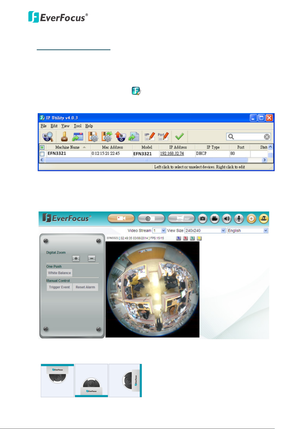
4. Accessing the Camera
You can look up the IP address and access the Web interface of the camera using the IP Utility (IPU)
software included in the software CD. Please connect the camera in the same LAN of your
computer.
1. Install and then start the IPU program . The following IPU window appears. The IPU will
automatically search the IP devices connected in the LAN.
Double click the IP address of the desired device, the login window pops up. Type the user ID
and password to log in. By default, the user ID is user1 and the password is 11111111. Click OK,
the Live View window appears.
Note that for the first time user, you will be prompted to choose a desired mounting type of
your fisheye camera. Click to select a mounting type, the above live view window appears.
Page 19

EFN Series Fisheye IP Camera
18
ons for viewing the camera feed. If asked,
To enable Remove Live View, Firmware Upgrade and ActiveX Prompt on Internet
Most networks uses DHCP to assign IP address, if you are unsure of your
Note:
1. You might be required to install some add-
click Run Add-on.
2.
Explorer, some settings have to be complete. Please refer to 4.2 Settings for Microsoft
Internet Explorer in the User’s Manual.
2. To optionally configure the Machine Name, IP Address, IP Type or Port Number using the IPU:
a. Log in the camera by checking the desired model and then click the Log in icon.
b. Type the Username and Password. Click the OK button, the Login status displays.
Note:
1. The default user ID is user1 and the default password is 11111111.
2. If you select more than one camera that has the same user ID / password, you will
be able to log in several cameras at once.
c. Right click the column to configure the settings. Click the Apply Changes button to
apply and save the settings.
Note:
network settings, please consult your network administrators for configuration details.
Page 20

EFN Series Fisheye IP Camera
19
To set up a static IP:
Select Static from IP Type drop-down list and set up the desired IP Address, for example,
172.17.0.145. Please also set up the Subnet Mask and Gateway. Click the Apply Changes button to
apply and save the settings.
To show the Subnet Mask and Gateway items on the title bar, right click the title bar to display the
Customize Columns window, select Subnet Mask and Gateway and then click OK.
Page 21

EFN Series Fisheye IP Camera
20
Cat 5
Straight Through Cable
High-speed modem
Internet
High-speed modem
Internet
Straight-through LAN patch cable
Router
Cat 5 Straight Through Cable
Left: Pinout of a straight-through cable.
5. Connecting to the Network
You can use one of the methods below to connect the camera to the network.
Direct High-Speed Connection
In a Direct High-Speed Connection, the camera connects directly to a modem without the need for a
router. You need to set the static or dynamic WAN IP address assigned by your ISP (Internet Service
Provider) in the camera’s configuration web pages. To access the camera, just type
“http://xxx.xxx.xxx.xxx”, where xxx.xxx.xxx.xxx is the IP address given by your ISP. If you have a
dynamic IP address, this connection may require that you use DDNS for a reliable connection.
Please refer to 7.1.1 Network (DDNS) in the User’s Manual.
Router or LAN Connection
This is the most common connection in which the IP camera is connected to a router and allows
multiple users on and off site to see the IP camera on a LAN/WAN (Internet). The camera must be
assigned an IP address that is compatible with its LAN. By setting up port forwarding on the router,
you can remotely access the cameras from outside of the LAN via the Internet. To remotely access
the Web interface of the IP camera, please refer to 7.1.1 Network (DDNS) in the User’s Manual. To
set up port forwarding, please consult the manual of the router.
Page 22

EFN Series Fisheye IP Camera
21
Cat 5
Right: Pinout of a crossed-over cable.
One-to-One Connection (Directly from PC to IP camera)
You can connect directly without using a switch, router or modem. However, only the PC connected
to the camera will be able to view the IP camera. You will also have to manually assign a compatible
IP address to both the computer and the IP camera. Unless the PC has another network connection,
the IP camera will be the only network device visible to the PC. See the diagram below:
6. Upgrading Firmware
You can upgrade camera’s firmware using the IP Utility software, which is included in the software
CD.
1. Install and then start the IPU program , the following IPU window appears. The IPU will
automatically search the IP devices connected in the LAN.
2. Log in the camera by checking the desired model and then click the Log in icon. The Log
in dialog box appears.
Page 23

EFN Series Fisheye IP Camera
22
select more than one camera that has the same user ID / password, you will be
Up to 10 cameras can be simultaneously upgraded to the latest firmware. If you
please make sure the Power Consumption of
3. Type the Username and Password. Click the OK button, the Login status displays.
Note:
1. The default user ID is user1 and the default password is 11111111.
2. If you
able to log in several cameras at once.
3.
connect the cameras to a PoE switch,
the PoE switch is sufficient.
4. Click the Upgrade Firmware button , a browsing window appears.
5. Select the firmware file (.evb) and then click Open. The IPU will automatically upgrade the
firmware. The camera will reboot once the upgrade process is complete.
Page 24

EverFocus Electronics Corp.
EverFocus Taiwan:
12F, No.79, Sec. 1, Shin-Tai Wu Road,
Hsi-Chih, Taipei, Taiwan
TEL: +886 2 2698 2334
FAX: +886 2 2698 2380
www.everfocus.com.tw
marketing@everfocus.com.tw
EverFocus Europe - Germany:
Albert-Einstein-Strasse 1, D-46446
Emmerich, Germany
TEL: +49 2822 93940
FAX: +49 2822 939495
www.everfocus.de
sales@everfocus.de
EverFocus China - Beijing:
Room 609, Technology Trade Building,
Shangdi Information Industry Base,
Haidian District, Beijing 100085, China
TEL: +86 10 6297 3336~39
FAX: +86 10 6297 1423
www.everfocus.com.cn
marketing@everfocus.com.cn
EverFocus USA - California:
1801 Highland Avenue, Unit A, Duarte, CA 91010, USA
TEL: +1 626 844 8888
FAX: +1 626 844 8838
www.everfocus.com
sales@everfocus.com
EverFocus Japan:
3F, Kuramochi, Building II
2-2-3 Koto-Bashi, Sumida-Ku,
Toky o, 1 30-0022, Japan
TEL: +81-3-5625-8188
FAX: +81 3 5625 8189
www.everfocus.co.jp
info@everfocus.co.jp
EverFocus India:
Suite 803, Housefin Bhavan, C-21,
Bandra Kurla Complex, Bandra (East),
Mumbai 400051, India
TEL: +91 22 6128 8700
FAX: +91 22 6128 8705
www.everfocus.in
sales@everfocus.in
Your EverFocus product is designed
and manufactured with high qua lity
materials and compone nts which can
be recycled and reused.
This symbol means that electrical and
electronic equipment, at their
end-of-life, should be disposed of
separately from your household waste.
Please, dispose of this equipment at
your local community waste
collection/recycling centre.
In the European Union there are
separate collection systems for used
electrical and electro nic product.
Please, help us to conserve the
environment we live in!
Ihr EverFocus Produkt wurde entwickelt
und hergestellt mit qualitativ
hochwertigen Materia lien und
Komponenten, die recycelt und wieder
verwendet werden können.
Dieses Symbol bedeutet, dass
elektrische und elektronische Geräte am
Ende ihrer Nutzungsdauer vom
Hausmüll getrennt entsorgt werden
sollen.
Bitte entsorgen Sie dieses Gerät bei
Ihrer örtlichen kommuna len
Sammelstelle oder im Recycling Centre.
Helfen Sie uns bitte, die Umwelt zu
erhalten, in der wir leben
!
EverFocus China - Shenzhen:
4F, No. 2, D4 Building, Wan Yelong
Industrial Park, Tangtou Road, Shiyan,
Baoan, Shenzhen, Guangdong 518101, China
TEL: +86 755 2765 1313
FAX: +86 755 2765 0337
www.everfocus.com.cn
marketing@everfocus.com.cn
EverFocus USA - New York:
415 Oser Avenue, Unit S, Hauppauge, NY 11788, USA
TEL: +1 631 436 5070
FAX: +1 631 436 5027
www.everfocus.com
sales@everfocus.com
EverFocus China - Shanghai:
Room 403, Ruijin Business Center, No.96, Zhaojiabang
Road, Luwan district, Shanghai 200020, China
TEL: +86 21 6471 2229 / 6471 2291
FAX: +86 21 6471 0566
www.everfocus.com.cn
marketing@everfocus.com.cn
P/N: 4605PF3320B042A
 Loading...