

Page 1
Volume
1
EverAccess
User Manual
Doooorr
D
SSeerriieess CCoonnttrroolllleerr
Moodduullee ffoorr FFlleexx
M
EEFFM
M--DDRR--11AA
Page 2

EVERFOCUS ELECTRONICS CORPORATION
EFM-DR-1A
Instruction Guide
© 2004 Everfocus Electronics Corp
1801 Highland Ave Duarte CA 91010
Phone 626.844.8888 • Fax 626.844.8838
All rights reserved. No part of the contents of this manual may be reproduced or transmitted in any
form or by any means without written permission of the Everfocus Electronics Corporation.
Page 3

T able of Contents
CHAPTER 1
Product Overview
Features
Parts List
Specifications
CHAPTER 2
Installing the Door Module into the Controller
Reader/Door Index Conversion
CHAPTER 3
Terminal/LED Definitions
Door Module Terminal Definition
Door Module LED Definition
CHAPTER 4
Wiring
Connection to Readers
RS232 Format
Wiegand 26 Format
Connection to Door Lock
Connection to an Electric Strike
Connection to a Magnetic Lock
Connection to Door Sensor
Connection to Request-to-exit
Connection to Alarm Output
Notes
1
1
1
2
3
4
5
5
6
8
8
8
9
9
10
10
10
11
11
13
Page 4

Chapter
1
Product Overview
The EverAccess® Flex Series controller (part number: EFC-02-1A) incorporates
state-of-the-art technology and modular design to provide reliable performance, userfriendly installation, expansion capabilities, and flexible but powerful configuration
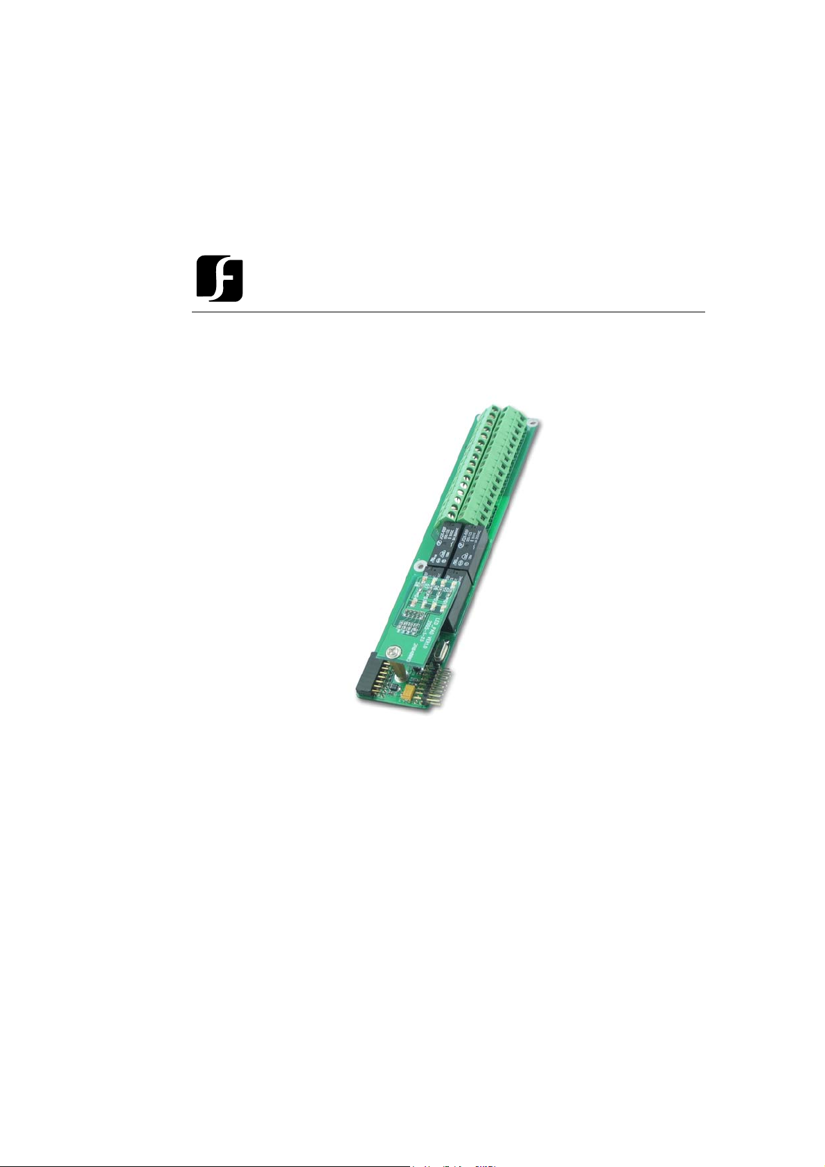
options. The door module (part number EFM-DR-1A) is the basic 2-door expansion
piece for the Flex Series Controller. It expands the control capabilities of the
controller by two readers.
The controller accommodates up to 4 door modules. The door modules are easily
installed; each module connects to the module to its right. The features for the door
module are listed in the next section.
Fea tures
¾ Supports two readers
¾ Supports both standard Wiegand format and EverAccess RS232 format
readers
¾ Provides 12VDC power supply to two readers
¾ Supports full controls on two doors, including door sensor, door lock relay,
request-to-exit
¾ Provides two alarm outputs
¾ Wiegand 26 and EverAccess RS232 formats supported
¾ Built-in transient voltage suppressor (TVS) to protect controller from electric
surge
¾ Large durable relay, max current draw up to 5A at 30VDC
¾ Built-in LEDs display the system status intuitively
Parts List
Please be careful when you unpack the box due to the electronics devices inside.
Check and make sure that you have all the items below inside the original box:
1
Page 5

¾ 3 mm*4 mm screws (to mount the module to the controller)
W
If an item appears to have been damaged in shipment, replace it properly in its carton
and notify the shipper. If any items are missing, notify your Everfocus Electronics
Corp. Sales Representative or Customer Service. The shipping carton is the safest
container in which the unit may be transported. Save it for possible future use.
In addition, the following EverAccess products are required for use with the door
module to achieve the correct functionality:
¾ EverAccess Flex Series Controller (part number EFC-02-1A)
¾ EverAccess proximity readers (part numbers ERR-871, ERK-871, ERM-
871)
Specifications
Items Parameter
Number of readers supported 2
Communication format
Number of doors supported 1 with both entry and exit readers
Input 2 for door sensors
Relay output 2 relay outputs for door lock
LED 2x4
Power supply Provided by the controller
Max current draw for relay outputs 5A
iegand26 or EverAccess RS-232 format
2 with entry reader for each door
2 for request-to-exit signals
2 relay outputs for alarm
2
Page 6
Chapte
r
2
Installing the Door
Module into the Controller
In this chapter, we will introduce how to mount the door module into an EverAccess
Flex Series controller. The definitions for the reader/door index is also explained.
The EverAccess Flex series controller can accommodates up to 4 door modules and
1 alarm module. The door modules are connected from right to left, with each new
module connecting easily in a cascading fashion. The door modules and the alarm
module can be placed in any sequence. The index will follow the same rules (refer to
next subsection).
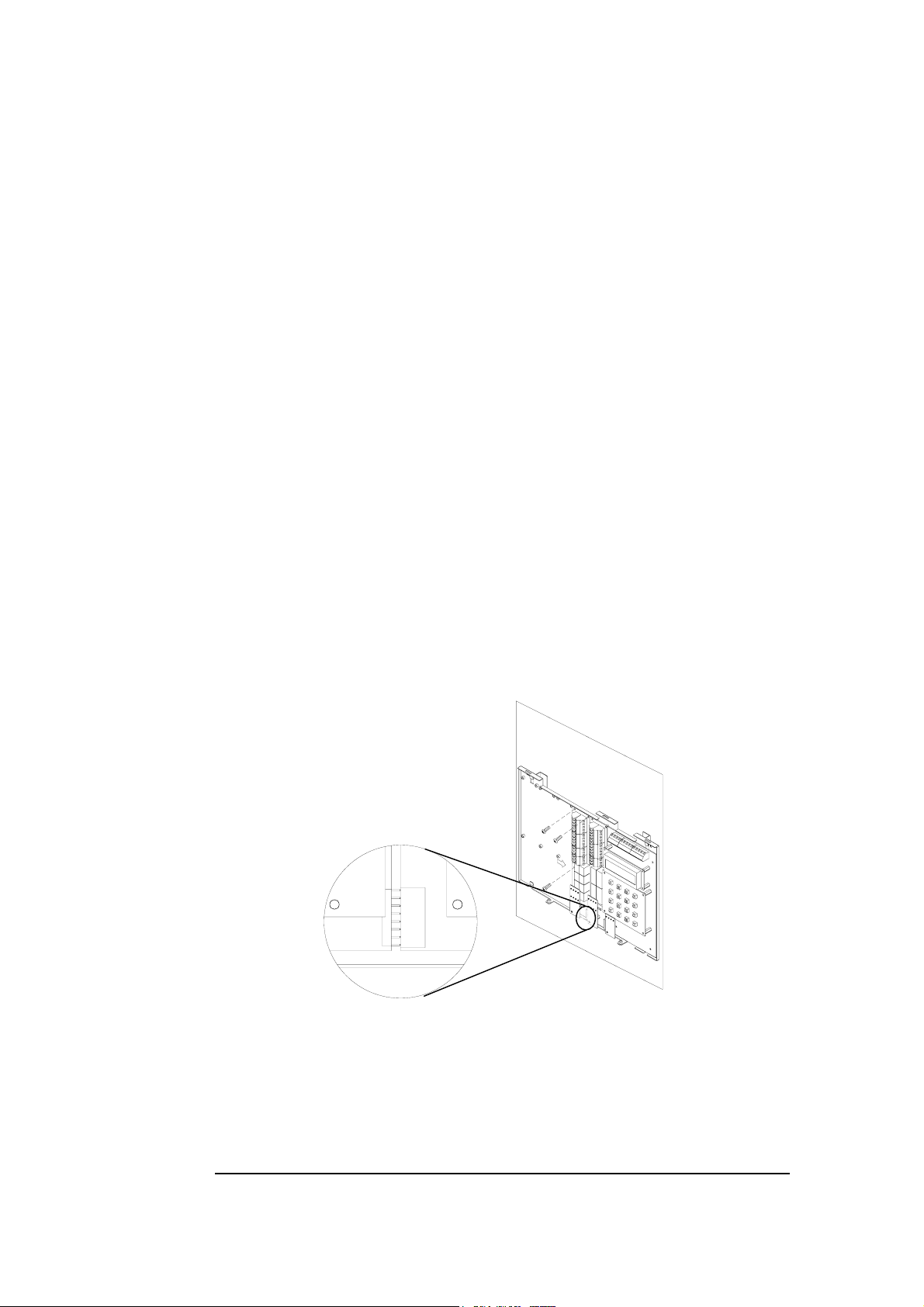
The steps to install a door module are described below:
2
1
Figure 2.1 Install a door Module to Controller
1. Connect the pins on the lower right corner of the new module to the connector
on the bottom left corner of the installed module. Make sure that the pins fit
snugly into the receiving module.
3
Page 7

2. Secure the module to the controller base board using the three screws (provided
in the module package).
Reader/Door Index Con version
One EverAccess Flex Series controller can accommodate up to 4 door modules, each
of which controls 2 readers. The index conversion of readers and is displayed below.
The readers/doors are counted 1 to 8 from right to left:
Figure 2.2 Reader/Door index conversions
Note: Each card reader can be associated with any door index. Please refer to section
5 for more details.
4
Page 8

Chapter
3
T erminal/LED Definitions
The definitions of the module terminals are presented in this chapter.
Door Module T erminal Definition
The terminals on the door modules are classified into two groups, each of which
controls two doors and the corresponding card readers. The right side terminals
(indexed from #1~#16) control one reader, while the left side terminals (indexed
from #17~#32) are responsible for the 2
As described in the “reader/door index conversion” section of the manual, the
reader’s index depends on the door module to which it is connected. For example,
consider one door module where terminals #1 ~#16 control Reader 1, and
#17~#32 control Reader 2. Table 3.1 shows the definition and wiring details for the
door module terminals.
nd
reader, as shown in the following figure.
Fig. 3.1 Door Module Terminal Definition
The definitions of the door module terminals are defined in the following table:
5
Page 9

Table 3.1 the definitions of the door module terminals
T
T
A
No Terminal
name
1 Reader1_Data0 Reader 1 Wiegand Data 0 17 Reader2_Data0 Reader 2 Wiegand Data 0
2 Reader1_Data1 Reader 1 Wiegand Data 1 18 Reader2_Data1 Reader 2 Wiegand Data 1
3 Reader1_DC
4 Reader1_GND GND for the Reader 1 20 Reader2_GND GND for the Reader 2
5 Reader1_ctrl Control line for reader 1 21 Reader2_ctrl Control line for Reader 2
6 RX_1 Port to TX signal to reader 1 22 RX_2 Port to TX signal to Reader 2
7 TX_1 Port to RX signal from reader 1 23TX_2 Port to RX signal from Rader 2
8 Door1_ Button
9 Door1_GND GND for terminal 8 & 10 25 Door2_GND GND for terminal 24 & 26
10 Door1_ Sensor Door sensor input for Door 1 26 Door2_ Sensor Door sensor input for Door 2
11 Door1_NO
12 Door1_COM
13 Door1_NC
14 Alarm1_NO
15 Alarm1_COM
16 Alarm1_NC
Power supply for reader 1.
Output +12 V voltage.
he request-to-exit button for
Door 1
Normally open pin for door
control relay 1
Common pin for door control
relay 1
Normally close pin for door
control relay 1
Normally open pin for alarm
output relay 1
Common pin for alarm output
relay 1
Normally close pin for alarm
output relay 1
Function No Terminal name Function
19 Reader2_DC
24 Door2_ Button
27 Door2_NO
28 Door2_COM
29 Door2_NC
30 Alarm2_NO
31 Alarm2_COM
32
larm2_NC
Power supply for Reader 2.
Output +12 V voltage.
he request-to-exit button for
Door 2
Normally open pin for door
control relay 2
Common pin for door control
relay 2
Normally close pin for door
control relay 2
Normally open pin for alarm
output relay 2
Common pin for alarm output
relay 2
Normally close pin for alarm
output relay 2
Door Module LED Definition
There are 8 LED indicators on each door module. The positions and indexes are
shown in Fig. 3.2. The definitions of these LED indicators are presented in Table 3.4
Fig. 3.2 Door Module LED Definition
The definitions of LEDs on the door module are defined in the following table:
6
Page 10

Table 3.2 The definition of LEDs on the door module
LED Meaning
1 On indicates the alarm relay #2 energized
2 On indicates reader #2 connected
3 On indicates the door sensor #2 is off (the door’s open)
4 On indicates door control relay #2 energized
5 On indicates the alarm relay #1 energized
6 On indicates reader #1 connected
7 On indicates the door sensor #1 is off (the door’s open)
8 On indicates door control relay #1 energized
7
Page 11

Chapte
r
4
Wiring
This chapter will describe, in detail, how to wire the terminals in the door modules.
Connection to Readers
As mentioned before, each door module can control up to two card readers with the
correct wiring. The supported reader formats are EverAccess RS232 and standard
Wiegand26. For instructions on connecting each type, please refer to Fig. 4.1 (a) for
the RS232 reader connection and Fig 4.1(b) for the Wiegand reader connection. (The
terminals for the 2
RS232 Format
nd
side of the door module are given in brackets)
3
(19)
(20)
4
(21)
5
6
(22)
7
(23)
Door
module
+12V
GND
Reader Ctrl
RX
TX
Red
Black
Yellow
Blue
Gray
1
4
G H I
7
PQRS
*
EverAccess
Fig. 4.1(a) Connection to the EverAccess reader using RS232 format
8
3
2
D E F
A B C
65
J K L
M N O
98
WXYZT U V
#0
Page 12

Wiegand 26 Format
(17)
1
2
(18)
3
(19)
4
(20)
5
(21)
Door
Reader_Data0
Reader_Data1
+12V
GND
Reader Ctrl
Green
Brown
Red
Black
Yellow
2
1
A B C D E F
56
G H I4J K L
7
PQRS T U V WXYZ
*
EverAccess
M N O
0#
3
98
module
Figure 4.1 (b) Connection to the EverAccess reader using Wiegand format
Each door module can provide +12V voltage for two card readers.
Twisted cable is recommended to connect the controller and card readers. The
maximum transmission distance between the reader and controller depends on the
gauge of the cable and the specification of the card reader. Please read the reader user
manual carefully before installing the cable for the readers.
Note: When installing a multi-reader system, it is strongly recommended that
all the card readers follow the same format, i.e. all of them are EverAccess
RS232 or Wiegand. Multiple formats could present compatibility problems: a
card may not be accepted by all the card readers in the system.
Connection to Door Lock
Each door module provides an interface to two door control relays. Terminal 11 ~13
are for door 1 and terminal 27~29 are for door 2. Terminal 12 and 28 are named
common terminal (COM). Terminal 13 and 29 are named normally closed terminal
(N.C.). Terminal 11 and 27 are named normally open terminal.
The electrical door lock must have a separate power supply. The power supply for the
electrical door lock depends on the specification of the lock. Carefully choose the
cable connecting the door locks to fit the current draw. Two common types of
electrical door locks in the market are electric strike locks and magnetic locks. The
connection methods for these examples are shown in Fig. 4.2 and 4.3 respectively.
9
Page 13

Connection to an Electric Strike
11
(27)
12
(28)
(29)
13
COM
Door
module
Fig.4.2 Example for connecting an electric strike
Connection to a Magnetic Lock
(27)1211
(28)
(29)
13
COM
N.O.
V+ V-
V-V+
N.C.
Door
module
Fig. 4.3 Example for connecting a magnetic lock
NOTE:
1. The maximum current outputted by the door lock relay on the door
module is less than 5A. If the current for door lock exceeds the capacity,
an external power relay is needed.
2. V+ in the figures represents one lead of power from an external power
source. When using DC Voltage for the lock, put the positive lead here.
When using AC the leads are interchangeable.
Connection to Door Sensor
The interface to the door sensor is also provided by the door module: door sensor 1
and door sensor 2 correspond to terminal 9 ,10 and 25, 26 on the door module.
10
Page 14

Door sensor
9
(25)
10
(26)
Door
module
Fig. 4.4 Example for connecting door sensor to controller
NOTE: Among these four terminals, terminal 9 and 25 are GND, shared by
the door sensor and request-to exit
Connection to Request-to-e xit
The door module also provides an interface to the request-to-exit button or sensor.
Door 1 and door 2 are connected to terminal 8, 9 and 24, 25 respectively.
(24)
(25)
8
9
EXIT
Door
module
Fig. 4.5 Connecting REX to controller
NOTE: Among these four terminals, terminal 9 and 25 are GND, shared by
the door sensor and request-to exit
11
Page 15

Connection to Alarm Output
A
A
The alarm module provides 8 alarm inputs and 8 alarm outputs. The user can assign
the corresponding relay status to the different events. There are three terminals:
COM, N.O and N.C. The wiring depends on the alarm device. Please read the user
manual of the external alarm devices before wiring. Using the 1
input as an example, the wiring is shown in Fig. 4.6 and 4.7.
st
channel alarm signal
25
26
27
N.O. terminal
C.terminal
N.O.
COM
larm
module
Fig. 4.6 Normally open connection for alarm output 1
C.terminal
25
26
27
COM
N.C. terminal
N.C.
Exteral
Alarming
Device
Exteral
Alarming
Device
larm
module
Fig. 4.7 Normally closed connection for alarm output 1
12
Page 16

Notes
13
Page 17

Head Office European Office
12F, No.79 Sec.1 Shin-Tai Wu Road, Albert-Einstein-Strasse 1,
Hsi-Chi, Taipei, Taiwan D-4644 6 E mmerich, German
Tel :+ 886-2-26982334 Tel : + 49-2822-9394-0
Fax :+ 886-2-26982380 Fax : + 49-2822-939495
USA Office Beijing office:
1801 Highland Ave.Duarte,CA Room 609,Technology Trade
Building.
91010 ,U.S.A Shangdi Information Industry Base,
Tel :+ 1-626-844-8888 Haidian District,Beijing China
Fax :+ 1-626-844-8838 Tel :+ 86-10-62971096
Fax :+ 86-10-62971423
Japan Office
1809 WBG Marive East 18F,
2-6 Nakase, Mihama-ku,
Chiba city 261-7118, Japan
Tel : + 81-43-212-8188
Fax : + 81-43-297-0081
EverAccess
 Loading...