

Page 1
Volume
1
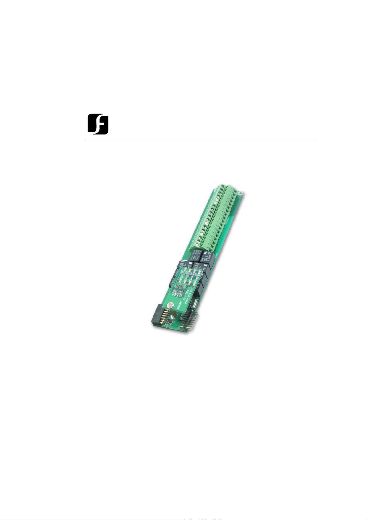
EverAccess
User Manual
AAllaarrm
m
Moodduullee ffoorr FFlleexx
M
SSeerriieess CCoonnttrroolllleerr
EEFFM
M--AALL--11AA
Page 2

EVERFOCUS ELECTRONICS CORPORATION
EFM-AL-1A
Instruction Guide
© 2004 Everfocus Electronics Corp
1801 Highland Ave Duarte CA 91010
Phone 626.844.8888 • Fax 626.844.8838
All rights reserved. No part of the contents of this manual may be reproduced or transmitted in any
form or by any means without written permission of the Everfocus Electronics Corporation.
Page 3

T able of Contents
CHAPTER 1
Product Overview
Features
Parts List
Specifications
CHAPTER 2
Installing an Alarm Module into the Controller
CHAPTER 3
Terminal/LED Definitions
Alarm Module Terminal Definition
Alarm Module LED Definition
CHAPTER 4
Wiring
Connection to Alarm Input
Connection to Alarm Output
Notes
1
1
1
2
3
4
4
5
6
6
6
8
Page 4

Chapter
1
Product Overview
The EverAccess® Flex Series controller (part number: EFC-02-1A) incorporates
state-of-the-art technology and modular design to provide reliable performance, userfriendly installation, expansion capabilities, and flexible but powerful configuration
options. The alarm module (part number EFM-AL-1A) is the alarm expansion unit
for the Flex Series Controller.
The alarm module provides 8 alarm inputs and 8 alarm outputs. With the expansion
alarm module and 4 door modules installed, the EverAccess Flex Series controller can
support up to 10 alarm inputs and 18 alarm outputs. The alarm module is installed in
a right to left cascading fashion. The features for the alarm module are listed in the
next section.
Fea tures
¾ Supports 8 alarm inputs
¾ Supports 8 alarm outputs
¾ Built-in transient voltage suppressor (TVS) to protect controller from electric
surge
¾ Large durable relay, max current draw up to 2A at 30VDC
¾ Built-in LEDs display the system status intuitively
Parts List
Please be careful when you unpack the box due to the electronics devices inside.
Check and make sure that you have all the items below inside the original box:
¾ 3 mm* 4mm screws (to mount the module to the controller)
If an item appears to have been damaged in shipment, replace it properly in its carton
and notify the shipper. If any items are missing, notify your Everfocus Electronics
Corp. Sales Representative or Customer Service. The shipping carton is the safest
container in which the unit may be transported. Save it for possible future use.
1
Page 5

In addition, the following EverAccess products are required for use with the door
module to achieve the correct functionality:
¾ EverAccess Flex Series Controller (part number EFC-02-1A)
Specifications
Items Parameter
Input 8 alarm inputs
Relay output 8 alarm outputs
LED 2x4
Power supply Provided by the controller
Max current draw for relay outputs 2A
2
Page 6

Chapte
r
2
Installing an Alarm
Module into the Controller
The EverAccess Flex series controller can accommodate up to 4 door modules and 1
alarm module. The alarm module connects to the door modules in a cascading
fashion. It can be installed in any of the 5 available positions; the order of installation
of the door modules and alarm module does not affect the functionality.
The steps to install an alarm module are described below:
2
1
Figure 2.1 Install an alarm module into Controller
1. Connect the pins on the lower right corner of the new module to the connector
on the bottom left corner of the installed module. Make sure that the pins fit
snugly into the receiving module.
2. Secure the module to the controller base board using the three screws (provided
in the module package).
3
Page 7

A
A
A
A
Chapter
3
T erminal/LED Definitions
The definitions of the module terminals are presented in this chapter.
Alarm Module T erminal Definition
There are 36 terminals on the alarm module. The positions and indexes are described
in Fig 3.1. The definitions are described in Table 3.1.
Fig. 3.1 Alarm Module Terminal Definition
The definitions of the alarm module terminals are defined in the following table:
Table 3.1 The definition of LEDs on the alarm module
Terminal
No
name
1 Alarm1_In
2 GND GND 20 GND GND
3 Alarm2_In
larm signal input 1 19Alarm5_In
larm signal input 2 21Alarm6_In
Function No
4
Terminal
name
Function
larm signal input 5
larm signal input 6
Page 8

4 Alarm3_In
A
A
A
A
A
5 GND GND 23 GND GND
6 Alarm4_In
7 Alarm1_NO Alarm 1 output for normally-open 25Alarm5_NO Alarm 5 output for normally-open
8 Alarm1_COM Alarm 1 output in common 26Alarm5_COM Alarm 5 output in common
9 Alarm1_NC Alarm 1 output for normally-close 27Alarm5_NC
10 Alarm2_NO Alarm 2 output for normally-open 28Alarm6_NOAlarm 6 output for normally-open
11 Alarm2_COM Alarm 2 output in common 29Alarm6_COMAlarm 6 output in common
12 Alarm2_NC Alarm 2 output for normally-close 30Alarm6_NCAlarm 6 output for normally-close
13 Alarm3_NO Alarm 3 output for normally-open 31Alarm7_NOAlarm 7 output for normally-open
14 Alarm3_COM Alarm 3 output in common 32Alarm7_COMAlarm 7 output in common
15 Alarm3_NC Alarm 3 output for normally-close 33Alarm7_NCAlarm 7 output for normally-close
16 Alarm4_NO Alarm 4 output for normally-open 34Alarm8_NOAlarm 8 output for normally-open
17 Alarm4_COM Alarm 4 output in common 35Alarm8_COMAlarm 8 output in common
18 Alarm4_NC Alarm 4 output for normally-close 36Alarm8_NCAlarm 8 output for normally-close
larm signal input 3 22Alarm7_In
larm signal input 4 24Alarm8_In
larm signal input 7
larm signal input 8
larm 5 output for normally-close
Alarm Module LED Definition
There are 8 LED indicators on each door module. The positions and indexes are
shown in Fig. 3.2. The definitions of the LED indicators are presented in Table 3.2.
Fig. 3.2 Alarm Module LED Definition
The definitions of LEDs on the alarm module are defined in the following table:
Table 3.2 The definition of the LED indication on the alarm module
LED Meaning LED Meaning
1 Alarm 1 5 Alarm 5
2 Alarm 2 6 Alarm 6
3 Alarm 3 7 Alarm 7
4 Alarm 4 8 Alarm 8
The alarm LED has four different indications:
Light off: No alarm alert for the alarmed zone.
Light flashes slowly: The alarmed zone is in the alert delay stage.
Solid light on: The alarm alert is on for the alarmed zone
Light flashes quickly: The alarmed zone is in danger; alarm signal is input
5
Page 9

Chapte
r
A
4
Wiring
This chapter will describe, in detail, how to wire the terminals in the door modules.
Connection to Alarm Input
The alarm signals other than the fire alarm and alarm input 0 are controlled by the
alarm module, which contains 8 alarm inputs and 8 alarm outputs. Using the 5
channel alarm signal input as an example, the method to connect the alarm module to
the alarm sensor is shown in Fig. 4.1:
Alarm input
GND
19
20
Alarm sensor
for alarm in 5
larm
module
Fig.4.1 Connecting alarm-sensor to controller
th
Connection to Alarm Output
The alarm module provides 8 alarm inputs and 8 alarm outputs. The user can assign
the corresponding relay status to the different events. There are three terminals:
COM, N.O and N.C. The wiring depends on the alarm device. Please read the user
manual of the external alarm devices before wiring. Using the 5
output as an example, the wiring is shown in Fig. 4. 2 and 4. 3.
6
th
channel alarm signal
Page 10

A
A
25
26
27
larm
module
N.O. termina
N.O
COM
.
C.terminal
Fig. 4. 2 Normally open connection for alarm output 5
Exteral
Alarm
Device
25
26
27
larm
module
COM
C.terminal
N.C. terminal
Exteral
Alarming
Device
N.C.
Fig. 4. 3 Normally closed connection for alarm output 5
7
Page 11

Notes
8
Page 12

Head Office European Office
12F, No.79 Sec.1 Shin-Tai Wu Road, Albert-Einstein-Strasse 1,
Hsi-Chi, Taipei, Taiwan D-4644 6 E mmerich, German
Tel :+ 886-2-26982334 Tel : + 49-2822-9394-0
Fax :+ 886-2-26982380 Fax : + 49-2822-939495
USA Office Beijing office:
1801 Highland Ave.Duarte,CA Room 609,Technology Trade
Building.
91010 ,U.S.A Shangdi Information Industry Base,
Tel :+ 1-626-844-8888 Haidian District,Beijing China
Fax :+ 1-626-844-8838 Tel :+ 86-10-62971096
Fax :+ 86-10-62971423
Japan Office
1809 WBG Marive East 18F,
2-6 Nakase, Mihama-ku,
Chiba city 261-7118, Japan
Tel : + 81-43-212-8188
Fax : + 81-43-297-0081
EverAccess
 Loading...