

EverFocus EFC301FM User Manual
User Manual
EFC301FR
EFC301FM
ID/Mifare IP@DOOR TCP/IP
Network Access Control System
Volume
1

EVERFOCUS ELECTRONICS CORPORATION
EFC301FR
EFC301FM
Instruction Guide
2014 EverFocus Electronics Corp
All rights reserved. No part of the contents of this manual may be reproduced or transmitted in any form or
by any means without written permission of the EverFocus Electronics Corporation.

TCP/IP Network Access Controller
I
TABLE OF CONTENTS
1 Introduction ............................................................................................................ 1
1.1 Features .................................................................................................................... 2
1.2 Specification ............................................................................................................. 2
1.3 Packing List ............................................................................................................... 3
1.4 Optional Device ........................................................................................................ 3
1.5 Installation Procedures ............................................................................................ 4
1.6 Installation Preparation ............................................................................................ 4
1.6.1 Obtain a Floor Plan ....................................................................................... 4
1.6.2 Determine the Hardware and Location ....................................................... 5
1.6.3 Determine the Number of Controllers According to System Structure ....... 6
2 Hardware Installation .............................................................................................. 7
2.1 Installing the Controller ............................................................................................ 7
2.2 Definitions of Terminal Block and LEDs .................................................................... 8
2.3 Installing and Connecting the Readers ................................................................... 10
2.3.1 RS232 .......................................................................................................... 11
2.3.2 Wiegand (Self-adaptive) ............................................................................. 11
2.4 Connecting to the Door Lock .................................................................................. 12
2.4.1 Connecting to an Electric Strike ................................................................. 12
2.4.2 Connecting to a Magnetic Lock .................................................................. 12
2.5 Connecting to the Door Sensor .............................................................................. 13
2.6 Connecting to the Door Button .............................................................................. 13
2.7 Connecting to the Fire Alarm ................................................................................. 13
2.8 Connecting to the Alarm Input ............................................................................... 13
2.9 Connecting to the Alarm Output ............................................................................ 14
3 Connection ............................................................................................................. 15
3.1 Connecting to the Computer through the TCP/IP .................................................. 15
3.2 Connecting to Power .............................................................................................. 15
3.3 Restoring the Controller ......................................................................................... 16
3.4 Before First Use ...................................................................................................... 16
4 Operation Instructions of Hardware........................................................................ 17
4.1 Operation Instructions of Keystrokes on the Reader ............................................. 17
4.2 Operation of Home Page ........................................................................................ 18
4.3 Main Menu of System Setting ................................................................................ 20
4.4 System Setting ........................................................................................................ 20
4.4.1 Set Language .............................................................................................. 21
4.4.2 Set Date Format ......................................................................................... 21

TCP/IP Network Access Controller
II
4.4.3 Set Date ...................................................................................................... 22
4.4.4 Set Time ...................................................................................................... 22
4.4.5 Set Summer Time (Daylight Savings) .......................................................... 23
4.4.6 Set SYS Password ........................................................................................ 23
4.4.7 Set ARM Password ..................................................................................... 24
4.4.8 Set Backlight ............................................................................................... 25
4.4.9 Restore Expired Event ................................................................................ 25
4.4.10 Erase All Events .......................................................................................... 25
4.4.11 Restore Factory Setting .............................................................................. 26
4.5 Card Setting ............................................................................................................ 27
4.5.1 Add Card ..................................................................................................... 27
4.5.2 Delete Card ................................................................................................. 28
4.5.3 Set Card Properties ..................................................................................... 29
4.6 Reader Setting ........................................................................................................ 33
4.6.1 Enter Reader Setting Menu ........................................................................ 33
4.6.2 Set SYS Reader ............................................................................................ 33
4.6.3 Set AUS Reader ........................................................................................... 34
4.7 Door Setting ............................................................................................................ 34
4.7.1 Set Open Time ............................................................................................ 35
4.7.2 Set Over Time ............................................................................................. 35
4.7.3 Door Access Mode ...................................................................................... 36
4.8 Alarm Setting .......................................................................................................... 36
4.8.1 Composition of Alarm ................................................................................ 36
4.8.2 Basic Configuration of the Alarm ............................................................... 36
4.8.3 Enter Alarm Setting Menu .......................................................................... 37
4.8.4 AlarmIN Setting .......................................................................................... 37
4.9 Address Setting ....................................................................................................... 39
4.10 Set Network ............................................................................................................ 40
4.10.1 DHCP Setting .............................................................................................. 40
4.10.2 Set IP Address ............................................................................................. 40
4.10.3 Reset Network Setting ................................................................................ 41
4.11 System Info ............................................................................................................. 41
4.12 Introduction of System Operation ......................................................................... 41
4.12.1 Door Open by Swiping Card ....................................................................... 41
4.12.2 Door Open with Single Password ............................................................... 42
4.12.3 Door Open with Both Card and Password ................................................. 42
4.12.4 Door Open with Multiple Cards ................................................................. 42
4.12.5 Specific Door Control Mode ....................................................................... 43
5 Software Introduction ............................................................................................ 44

TCP/IP Network Access Controller
III
5.1 Main Functions ....................................................................................................... 44
5.2 Profiles of Highlighted Features ............................................................................. 44
5.3 TCP/IP-based Architecture of Access Control System............................................ 45
6 Getting Started ....................................................................................................... 46
6.1 Quick Start .............................................................................................................. 46
6.1.1 Set Access Rule ........................................................................................... 46
6.1.2 Multiple Card Addition Methods ............................................................... 47
6.1.3 Set Department and Cardholder ................................................................ 48
6.1.4 Configure and Manage Attendance ........................................................... 49
6.1.5 Real-time Monitoring ................................................................................. 50
6.1.6 Export Function .......................................................................................... 50
6.1.7 Print Function ............................................................................................. 51
6.2 First Use .................................................................................................................. 52
6.2.1 Login Page................................................................................................... 52
6.3 Get Familiar with the Browser Page ....................................................................... 53
6.3.1 Introduction of the Main Page ................................................................... 53
6.3.2 Menu .......................................................................................................... 53
6.3.3 Control Panel .............................................................................................. 54
6.3.4 System Event Record .................................................................................. 55
7 Basic Setting ........................................................................................................... 57
7.1 Change Password ................................................................................................... 57
7.2 Set User and Authority ........................................................................................... 58
7.3 User Group ............................................................................................................. 60
7.3.1 Add User Group .......................................................................................... 60
7.3.2 Change User Group .................................................................................... 60
7.3.3 Delete User Group ...................................................................................... 60
7.4 User Setting ............................................................................................................ 61
7.4.1 Add User ..................................................................................................... 61
7.4.2 Edit User ..................................................................................................... 62
7.4.3 Delete User ................................................................................................. 62
7.4.4 Export User Information ............................................................................. 62
7.4.5 Print User Information ............................................................................... 63
7.4.6 Search User ................................................................................................. 63
7.5 Local Server ............................................................................................................ 63
7.6 System Upgrade ..................................................................................................... 64
7.6.1 Online Upgrade .......................................................................................... 64
7.6.2 Local Upgrade ............................................................................................. 64
8 Cardholder ............................................................................................................. 66
8.1 Department Setting ................................................................................................ 66

TCP/IP Network Access Controller
IV
8.1.1 Add Department ......................................................................................... 66
8.1.2 Edit Department ......................................................................................... 67
8.1.3 Delete Department..................................................................................... 67
8.2 Cardholder Setting ................................................................................................. 68
8.2.1 Add Cardholder .......................................................................................... 68
8.2.2 Change Cardholder ..................................................................................... 71
8.2.3 Delete Cardholder ...................................................................................... 72
8.2.4 Export Cardholder Information .................................................................. 73
8.2.5 Print Cardholder Information ..................................................................... 73
8.2.6 Query Cardholder ....................................................................................... 73
8.3 Import Cardholders ................................................................................................ 73
9 Real-time Monitoring ............................................................................................. 75
9.1 Real-time Event ...................................................................................................... 75
9.2 Report ..................................................................................................................... 76
9.2.1 Query Cardholder Information ................................................................... 76
9.2.2 Export Cardholder Information .................................................................. 76
9.2.3 Print Cardholder Information ..................................................................... 76
10 Maintenance .......................................................................................................... 77
10.1 Data Backup ............................................................................................................ 77
10.1.1 Manual Backup ........................................................................................... 77
10.1.2 Automatic Backup ...................................................................................... 78
10.2 Restore ................................................................................................................... 78
10.2.1 Restore from FTP ........................................................................................ 78
10.2.2 Restore from Local ..................................................................................... 79
10.3 Purge Out-of-date Data .......................................................................................... 79
11 Controller Management ......................................................................................... 80
11.1 Controller Setting ................................................................................................... 80
11.1.1 Change Controller Information .................................................................. 80
12 Access Rule............................................................................................................. 83
12.1 Date Type ............................................................................................................... 83
12.1.1 Add Date ..................................................................................................... 83
12.1.2 Delete Date ................................................................................................. 84
12.2 Door Schedule ........................................................................................................ 85
12.3 Group Schedule ...................................................................................................... 86
12.3.1 Add Group Schedule ................................................................................... 86
12.3.2 Delete Group Schedule .............................................................................. 87
12.3.3 Set Group Schedule .................................................................................... 87
12.4 Access Group .......................................................................................................... 88
12.4.1 Add Access Group ....................................................................................... 88

TCP/IP Network Access Controller
V
12.4.2 Delete Access Group .................................................................................. 89
13 Card Management .................................................................................................. 90
13.1 Card Setting ............................................................................................................ 90
13.1.1 Add (Register) Card .................................................................................... 91
13.1.2 Edit/Change Card........................................................................................ 92
13.1.3 Change Cards in Batch ................................................................................ 93
13.1.4 Delete Card ................................................................................................. 93
13.1.5 Delete All Cards .......................................................................................... 93
13.1.6 Export Card Information ............................................................................. 93
13.1.7 Print Card Information ............................................................................... 93
13.1.8 Query Card.................................................................................................. 93
13.2 Card Import ............................................................................................................ 94
14 Report .................................................................................................................... 96
14.1 Card Report ............................................................................................................ 96
14.1.1 Query Card Information ............................................................................. 96
14.1.2 Export Card Information ............................................................................. 96
14.1.3 Print Card Information ............................................................................... 96
14.2 Card-dependent Event ........................................................................................... 97
14.2.1 Query Card-Related Events ........................................................................ 97
14.2.2 Import Card-Related Events ....................................................................... 97
14.2.3 Print Card-Related Events .......................................................................... 97
14.3 Card-independent Event ........................................................................................ 97
14.3.1 Query Card-Irrelevant Events ..................................................................... 98
14.3.2 Import Card-Irrelevant Events .................................................................... 98
14.3.3 Print Card-Irrelevant Events ....................................................................... 98
15 Basic Attendance Management .............................................................................. 99
15.1 Attendence Time Setting ........................................................................................ 99
15.2 Edit Attendence Time ............................................................................................. 99
15.2.1 Query Attendance Time ........................................................................... 100
15.2.2 Export Attendance Information ............................................................... 100
15.2.3 Print Attendance Information .................................................................. 100
15.3 Week Holiday Setting ........................................................................................... 100
15.3.1 Edit Weekend ........................................................................................... 101
15.3.2 Query Weekend........................................................................................ 101
15.3.3 Export Weekend ....................................................................................... 101
15.3.4 Print Weekend .......................................................................................... 102
15.4 Special Holiday Setting ......................................................................................... 102
15.4.1 Add Special Date ....................................................................................... 102
15.4.2 Query Special Holiday Setting .................................................................. 103

TCP/IP Network Access Controller
VI
15.4.3 Edit Special Date ....................................................................................... 103
15.4.4 Delete Special Date .................................................................................. 103
15.4.5 Export Special Date .................................................................................. 104
15.4.6 Print Special Date ..................................................................................... 104
16 Attendance Exception ........................................................................................... 105
16.1 No-Access-Attendance ......................................................................................... 105
16.1.1 Add No-Access-Attendance ...................................................................... 105
16.1.2 Query of Registration of Not Swiping a Card ........................................... 106
16.1.3 Edit Record of Not Swiping a Card ........................................................... 106
16.1.4 Delete Registration of Not Swiping a card ............................................... 107
16.1.5 Export Registration of Not Swiping a card ............................................... 107
16.1.6 Print Registration of Not Swiping a card .................................................. 107
16.2 Time-off Enroll ...................................................................................................... 107
16.2.1 Add Time-off Enroll .................................................................................. 107
16.2.2 Query Time-off Enroll ............................................................................... 108
16.2.3 Edit Time-off Enroll ................................................................................... 108
16.2.4 Delete Leave Record ................................................................................. 109
16.2.5 Export Time-off Enroll .............................................................................. 109
16.2.6 Print Time-off Enroll ................................................................................. 109
16.3 Overtime Enroll .................................................................................................... 109
16.3.1 Add Overtime Enroll ................................................................................. 110
16.3.2 Query Overtime Enroll ............................................................................. 110
16.3.3 Edit Overtime Enroll ................................................................................. 111
16.3.4 Delete Overtime Enroll Records ............................................................... 112
16.3.5 Export Overtime Enroll Records. .............................................................. 112
16.3.6 Print Overtime Enroll Record. .................................................................. 112
17 Attendance Report ............................................................................................... 113
17.1 Original Access Record ......................................................................................... 113
17.1.1 Query Original Access Record .................................................................. 113
17.1.2 Export Original Access Record .................................................................. 113
17.1.3 Print Original Access Record .................................................................... 113
17.2 Report by Cardholder ........................................................................................... 114
17.2.1 Generate Report by Cardholder ............................................................... 114
17.2.2 Export Report by Cardholder ................................................................... 114
17.2.3 Print Report by Cardholder ...................................................................... 114
17.3 Statistics by Cardholder ........................................................................................ 115
17.3.1 Generate Statistics by Cardholders .......................................................... 115
17.3.2 Export Statistics by Cardholders............................................................... 115
17.3.3 Print Statistics by Cardholder ................................................................... 115

TCP/IP Network Access Controller
VII
17.4 Statistics by Department ...................................................................................... 115
17.4.1 Generate Statistics by Department .......................................................... 116
17.4.2 Export Statistics by Department .............................................................. 116
17.4.3 Print Statistics by Department ................................................................. 116
1
1 Introduction
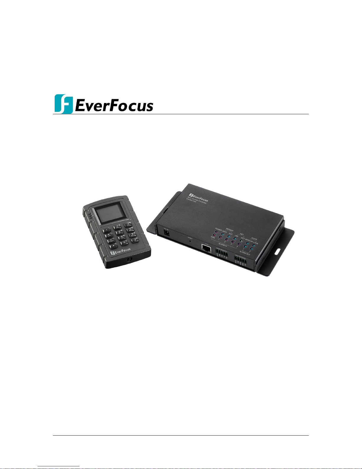
The EFC301F is a Linux-based IP access control system combined with a card reader and a
door controller. The series comes in two models, EFC301FR and EFC301FM, supporting ID
card and MIFARE card respectively.
The EFC301F system is designed to control single door, and connect up to two readers. You
can simply connect the system to the network using a Cat 5 cable or through the PoE and to
power through the PoE port. Built-in with an RFID module, the controller can manage more
than 100,000 cards and 1,000,000 event records, and support 2,048 management groups.
The user-friendly electronic map management function makes it easy to manage the access
or events through the Web browser. You can also easily configure the operation using the
keypad on the reader.
• EFC301FR: Supports ID card
• EFC301FM: Supports MIFARE card
Figure 1-1
Chapter
1

TCP/IP Network Access Controller
2
1.1 Features
Network access through CAT 5 cable ( 10M / 100M Ether net) or PoE
Remote setting, control and management; no software needed to be installed
Secure access through the Web browser is guaranteed by SSL (Secure Socket Layer)
Plug-and-play through DHCP or static IP
Multiple languages support and multilingual Web pages: English, Simplified Chinese
and Russian
On-line system update support
Control multiple controllers through central management software
Manage up to 100,000 cards and 1,000,000 event records
2,048 management groups support
Manage 10 time periods every day, with a minimum interval of 1 min
3 data types setting, up to 255 date settings support
Real-time electronic map display and edit support
Real-time event records support
Powerful management function: Access management according to time, date,
location, authority of card holder, etc.
Powerful alarm access function and protection setting / withdrawal function in the
protection area
1.2 Specification
Operating System
Linux embedded
Database
Built-in
Memory
512 M
Web Setting Page
Support setting, monitoring and management
Maximum Card Amount
100,000
Maximum Even Records
1,000,000
Door Control
Single door
Card password
8 digits
System password
8 digits
Protection Setting /
Withdrawal Password
8 digits
Alarm Input
5 inputs (1 fire alarm; 4 common alarms)
Alarm Output
2 outputs
Network Interface
100M ethernet interface
Baud Rate
9600 bps
Card Reading Distance
5 ~ 10 cm
Card Reading Time
200 ms
Programmable Time
Periods
Each day can be divided into 10 time-period with a
minimum time interval of 1 min.
Programmable Date
Each door supports independent 10 date settings (from
Sunday to Monday, and 3 customized dates)
Management Group
2,048
Management Plans
2,048
Daylight Saving Time
Yes
Card Expiration
Yes

TCP/IP Network Access Controller
3
Power-Fail Protection
Yes
Real-Time Clock Yes
Anti-Dismantle Switch
Yes, NC
Keypad
3×4
Access Control Mode
13 modes
Multi-Card Door Open
Mode
supports 4 × 4 locking class, and allows 4-shift × 4-card
(max.) multi-card door open setting
LCD Display
With Backlight,4×9 for Simplified Chinese,4×18 for English
and Russian
Buzzer
Built-in
Driving Current of Door
4A (Max.)
Driving Current of
Alarm Relay
4A (Max.)
Power Supply
POE,12 VDC±15%,1A
Power Consumption
< 10W
Maximum Current
600mA
Dimension (L x W x H)
123mm×77mm×27mm
Operating Temperature
0
℃~40℃
Operating Humidity
5%~95% (no condensation)
1.3 Packing List
Please check that there is no missing item in the package before installing.
EFC301F IP Access Control System x 1 (1 controller + 1 reader)
User’s Manual x 1
Mounting Kit for installing the reader:
- M3 mm *6 mm Screw x 2 sets
- ST2.9 mm *6 mm Screw x 2
- L-Type Spanner
Note: Contact the shipper if any items appear to have been damaged in the shipping
process. If any items are missing, notify your EverFocus Electronics Corp. Sales
Representative or Customer Service Branch. Please also keep the shipping carton for
possible future use.
1.4 Optional Device
Optional device can expand your controller’s capabilities and versatility. Please contact your
dealer for more information.
EverFocus USB desktop card reader (ERU171/181)
TCP/IP Network Access Controller
4
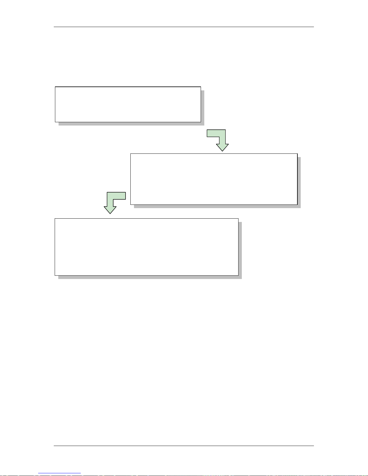
1.5 Installation Procedures
The Installation has three procedures described as below. Each procedure will be
introduced in the following sections in detail.
1.6 Installation Preparation
Before installation, users are advised to collect information properly which will make the
installation more smoothly and helps to reduce time and energy cost. For professional
constructors, the information below will be of great use.
1.6.1 Obtain a Floor Plan
Obtain a floor plan of the building in which the access control system is to be installed.
Obtaining a floor plan helps the installer determine what components need to be installed,
and where. It also is essential in determining the length of cable needed to connect readers
to the controller. A floor plan can be a blue print of the building, a design, or simply a
drawing of the facility. Any document showing the footprint of the building can be used.
The dimensions are important to note, especially when determining cable lengths. A floor
plan may be obtained from your local city hall.
Step 1: Installation Preparation
• Obtain a floor plan
• Determine the hardware and location
Step 2: Hardware Installation
• Installing the controller
• Connecting to the door lock / open button / sensor / bell
• Connecting the controller to the network
• Connecting to the alarm input / output
Step 3: Software Setup / Configuration
• Log in controller built-in software through IE on computer
• Set up user account for user software
• Set up controller and other equipment
• Set holidays, shifts and door access rule
• Log in card and set up card attributes
TCP/IP Network Access Controller
5
1.6.2 Determine the Hardware and Location
Determine which hardware to use and where it will be installed. This is the most crucial step
in the preparation stage. First, determine how many access points, or doors, need to be
managed by the access control system. These access points will control the security of the
facility, and can limit the entry and exit to and from any given area of the building. After
deciding which doors need to be controlled, the user must also determine the level of
security needed at each door. There are many ways to manage each door, using different
resources. These resources include, but are not limited to: proximity readers, mag strip
readers, relays, and request to exits. A few common door configurations are described
below:
1.6.2.1 One Set of EFC301F (One Reader) – The Basic Door Entry Control
The most basic configuration involves one EFC301F (controller + reader) and an electric
strike. In this configuration, a person presents a card to the reader, and is either granted
or denied access. The electric strike unlocks if the system grants access. Another
variation of this scenario involves setting the system up to monitor whether the door is
open, which allows the system to protect against propped open doors, or doors being
held open for too long.
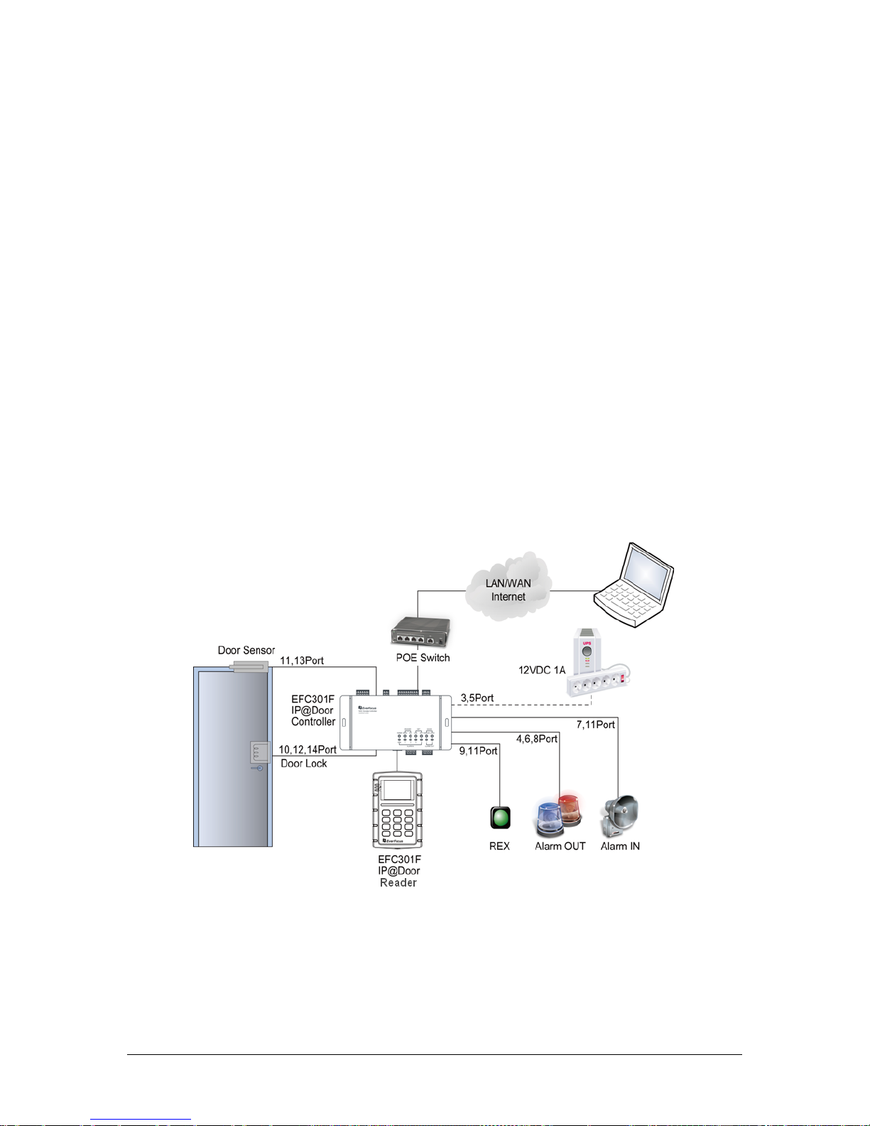
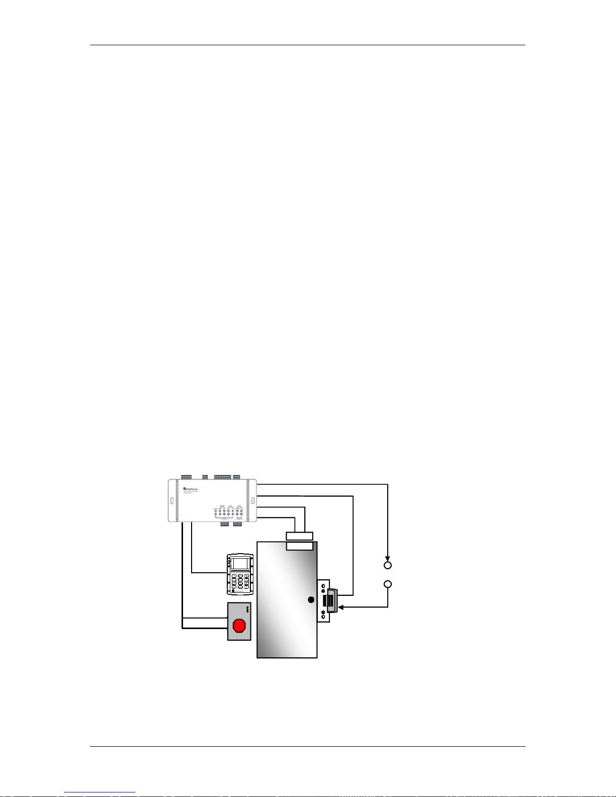
1.6.2.2 One Set of EFC301F (One Reader) + One Door Open Button – Control of Exit
Adding a door open button to the above scenario allows the system to control when to
allow people to exit through a door. The door open button equipment includes a
button which has to be pressed when a card holder exits, or a door sensor. The
equipment should be arranged on the secure side of the door.
Additional
Power Supply
V-
V+
Door Lock
Door
Sensor
EFC301F
Reader
EFC301F Controller
Door Open Button
Figure 1-2

TCP/IP Network Access Controller
6
1.6.2.3 One Set of EFC301F (Two Readers) – Control of both Entry and Exit
When the security grade is relatively high or the administrator requires the card holders
to get in or out at fixed time or date through specific door, one controller and two
readers are needed. Additional installation of one reader on the side of the door
requires the card holders to swipe the card when exiting and entering. This rule has
more reliable security regarding who can enter and who can exit and the administrator
can also master the entry and exit time of card holders.
1.6.3 Determine the Number of Controllers According to System Structure
Determine how many controllers and network interfaces are required.
Each EFC301F Controller can connect up to two readers. If the system requests installation
of more than two readers, the number of the controller will be increased. You can refer to
Chapter 3 for more details.

TCP/IP Network Access Controller
7
2 Hardware Installation
After the preparation work is finished, user can start installation. This chapter mainly
introduces how to install the hardware part, which is divided into four steps:
1. Install the controller.
2. Install the reader and connect the reader to the controller.
3. Connect the electric strikes or magnetic locks.
4. Connect the controller to the system computer and reader (optional).
2.1 Installing the Controller
The controller should be installed in an easily-accessible position. However, it should be
noticed that the controller is the core part of the entire system and can be used to change
database. After the installation site is selected, a relative secure clean position in which the
administrator is easy to operate should be selected. In order to facilitate power supply and
communication, a prepared wire chase must be arranged on the periphery of the controller
before installing the controller.
For installing the controller to the desired location, two screws or anchors have to be
prepared.
Screws
Wall
Chapter
2
TCP/IP Network Access Controller
8
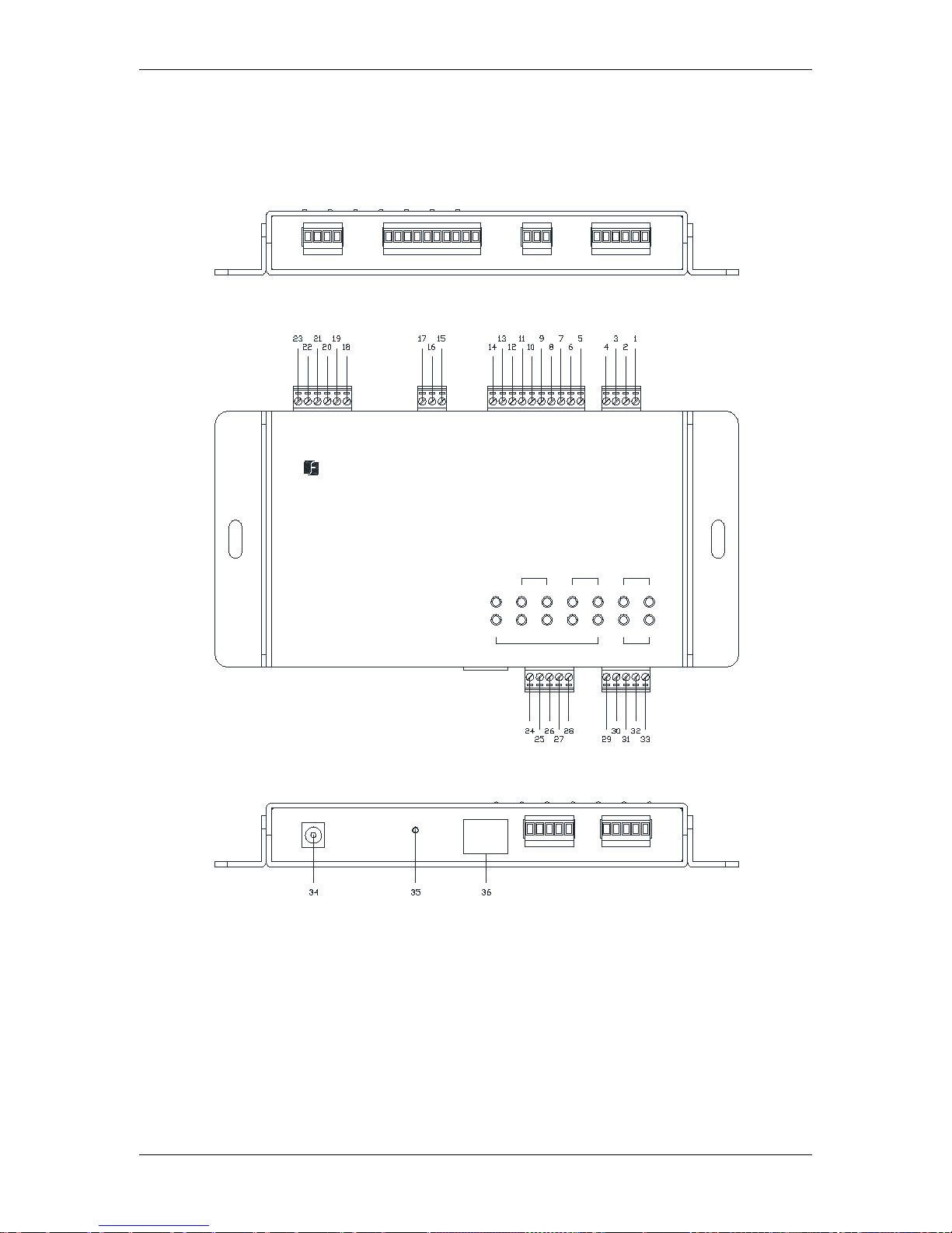
2.2 Definitions of Terminal Block and LEDs
You can connect up to two readers to the EFC301F controller. The images and tables below
show the information about the terminal block and LEDs.
POW
ER SENSOR1LOCK
3
AL
ARM IN
2 4
MA
IN A
UX
1 2FIRE
ALA
RM OU
T
DOORREADER
EverFocus
ControlUnit
RE
SET MAINREADER AUXREADERDCIN
CT
T
R
G
DCO
DAT
CT
DCO
G
DAT
NAV Access Controller
LNK ACT
NET
LAN
A
LA
RM
I
N D
OOR LOCKBUTTON& SENSOR ALARMOUT
OOMCOOM
C
M
E
D
D
D
D
D
TTON
D
NSOR
D

TCP/IP Network Access Controller
9
Table 2-1 Terminal Block on the Controller
No.
Terminal Name Function
1
Button &Sensor
GND
Ground
2
SENSOR
Door sensor input
3
GND
Ground
4
BUTTON
Door button input
5
Alarm IN
GND
Ground for alarm input
6
IN 4
Alarm input 4
7
GND
Ground for alarm input
8
IN 3
Alarm input 3
9
GND
Ground for alarm input
10
IN 2
Alarm input 2
11
GND
Ground for alarm input
12
IN 1
Alarm input 1
13
GND
Ground for alarm input
14
FIRE
Fire alarm input
15
Door Lock
NC
Normally closed end of door lock
16
COM
Common terminal of door lock output
17
NO
Normally opened end of door lock
18
Alarm OUT
2NC
Normally closed end of alarm output 2
19
2COM
Common terminal of alarm output 2
20
2NO
Normally opened end of alarm output 2
21
1NC
Normally closed end of alarm output 1
22
1COM
Common terminal of alarm output 1
23
1NO
Normally opened end of alarm output 1
24
Main Reader
DCOUT
12 VDC power output for reader
25
GND
Ground
26
RXD
RS232-TXD (transfer)
27
TXD
RS232-RXD (receive)
28
CTRL
Controller output
29
Aux Reader
DCOUT
12 VDC power output for reader
30
GND
Ground
31
DATA0
Wiegand DATA0
32
DATA1
Wiegand DATA1
33
CTRL
Controller output
34
DC IN
12 VDC power input
35
RESET
Reset button
36
LAN
LAN port (network / PoE)

TCP/IP Network Access Controller
10
Table 2-2 Definition of LEDs on the Controller
LED Definitions
POWER
Light up to indicate the power is on.
READER
MAIN
Light up to indicate the main reader is ready to use.
AUX
Light up to indicate the secondary reader is ready to use.
DOOR
SENSOR
Light up to indicate the door is opened.
LOCK
Light up to indicate the door is closed.
ALARM IN
FIRE
Blink to indicate the fire alarm is triggered.
Continuously light up to indicate its in the protection status.
1
Continuously light up to indicate the protection setup success
(in the protection setup statue).
Blink slowly to indicate the protection setup is progressing.
Blink quickly to indicate the alarm is triggered.
No light to indicate no protection setup or failure of alarm
input setup.
2
3
4
ALARM
OUT
1
Continuously light up to indicate the alarm output 1 is active.
2
Continuously light up to indicate the alarm output 2 is active.
2.3 Installing and Connecting the Readers
The reader has to be installed nearby the door and connected to the controller directly. You
can connect up to two readers to the EFC301F controller. The general procedure is
described below:
1. Mount each reader, following the instructions included with the reader. Typically, this
will include drilling two holes in the mounting wall, and then using the reader
mounting hardware to secure the reader to the mounting wall.
2. Once the readers are mounted, connect them to the door module. For wiring
definitions, please see previous sections in this manual.
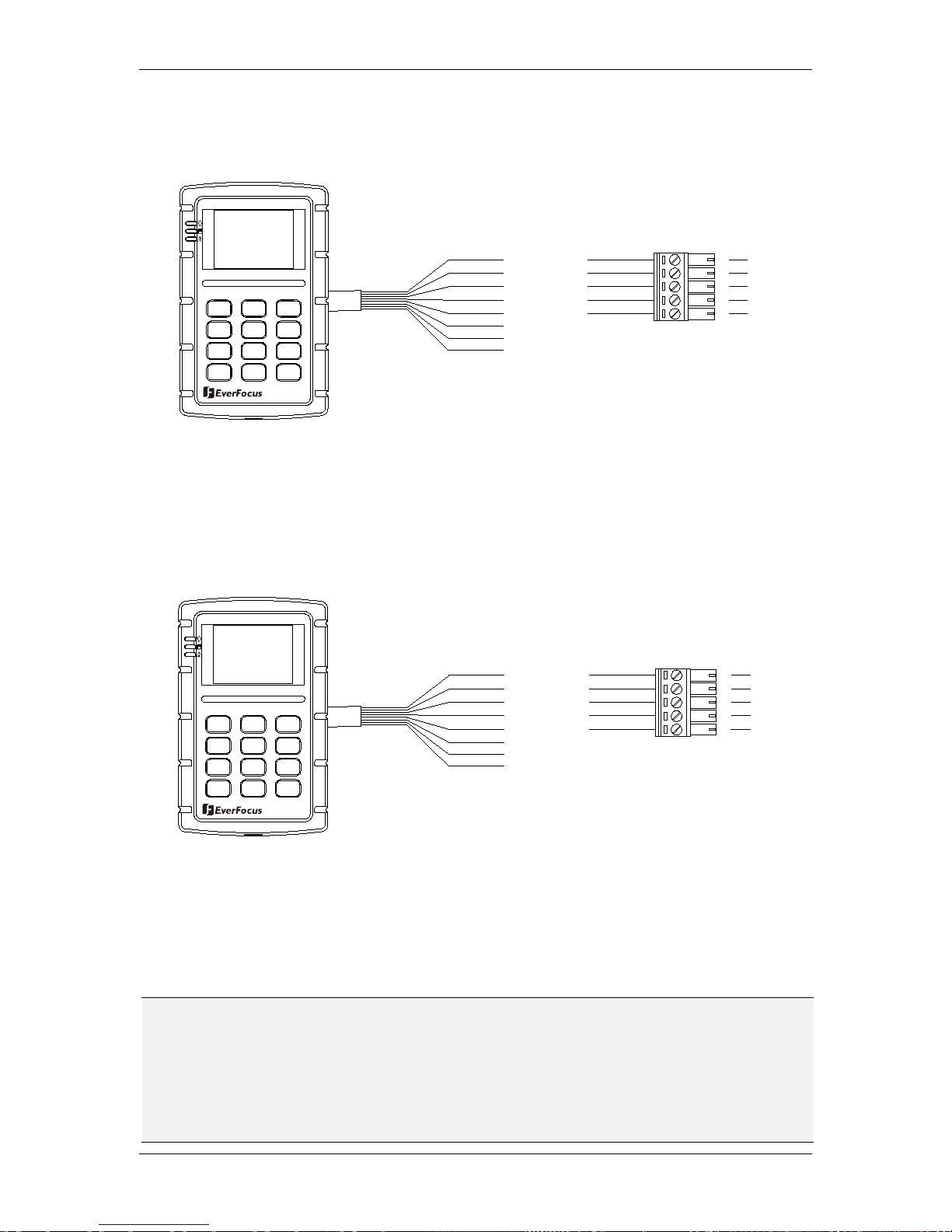
The EFC301F controller can control up to two readers. The supported reader formats are
EverAccess RS232 and Wiegand format. For instructions on connecting each type, please
refer to Figure 2-1 for the RS232 reader connection and Figure 2-2 for the Wiegand reader
connection.
TCP/IP Network Access Controller
11
2.3.1 RS232
Terminal 29-33 signifies RS232 reader.
Figure 2-1 Connecting to the reader using RS232 format
2.3.2 Wiegand (Self-adaptive)
Terminal 34-38 signifies Wiegand reader. The controller will automatically adjust to the
Wiegand format of the card reader.
Figure 2-2 Connecting to the reader using Wiegand format
The EFC301F controller can provide 12 VDC voltage for two card readers. Twisted cable is
recommended to connect the controller and card readers.
Note: The EFC301F controller can connect up to two readers. The Main Reader terminal,
designed for connecting to the RS232 reader, allows the
controller to display the
management user interface on the LCD display of the reader. Therefore, it is required to
connect an EverFocus RS232 reader with LCD display to the Main Reader terminal. The
AUX Reader terminal is only for connecting to the Wiegand reader
for indicating the door
status and alarm signals.
1
2
A B C
D E F
3
G H I4J K L
5 6
M N O
7
PQRS
T U V WXYZ
*
0 #
Red
Black
Yellow
Gray
Blue
Reader Ctrl
RX
TX
GND
+ 12V
98
32
33
30
31
29
Y
el
low
GND
+ 1
2V
37
38
35
36
3
4
Read
er
Ct
r
l
Black
R
ed
1
2
A B
C
D E F
3
G
H I
4
J K
L
5 6
M
N O
7
PQRS
T U V WXYZ
*
0 #
98
Re
ad
e
r_
Dat
a0
Re
a
de
r_D
ata
1
Bro
wn
Green
24
25
26
27
28
29
30
31
32
33
TCP/IP Network Access Controller
12
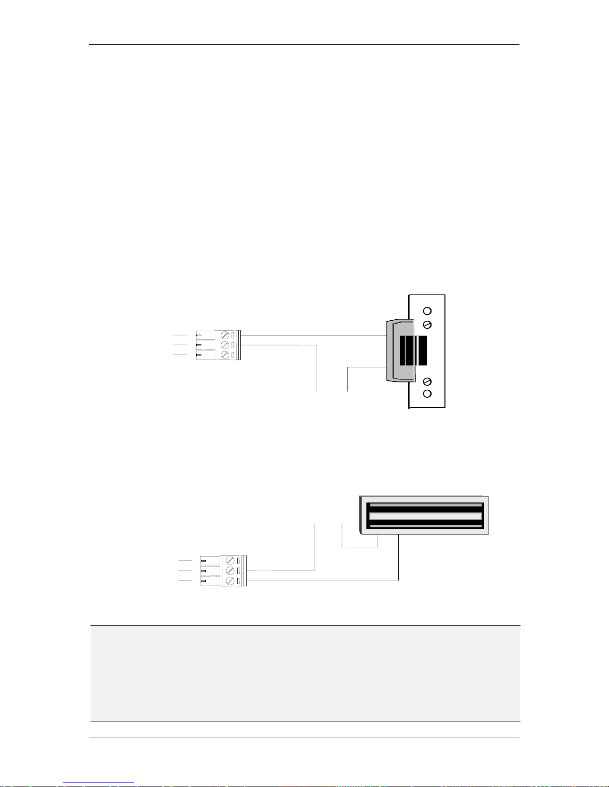
2.4 Connecting to the Door Lock
The controller provides one Door Lock terminal for locking / unlocking the door. You can
connect either an electric strikes or magnetic locks to the reader. Terminal 15 is used for
normally opened terminal (N.O.). Terminal 16 is used for common terminal (COM). Terminal
17 is used for normally closed terminal (N.C.).
The electrical door lock must have a separate power supply. The power supply for the
electrical door lock depends on the specification of the lock. Carefully choose the cable
connecting the door locks to fit the current draw. Two common types of electrical door
locks in the market are electric strike locks and magnetic locks. The connection methods for
these examples are shown in Figure 2-3 and Figure 2-4 respectively.
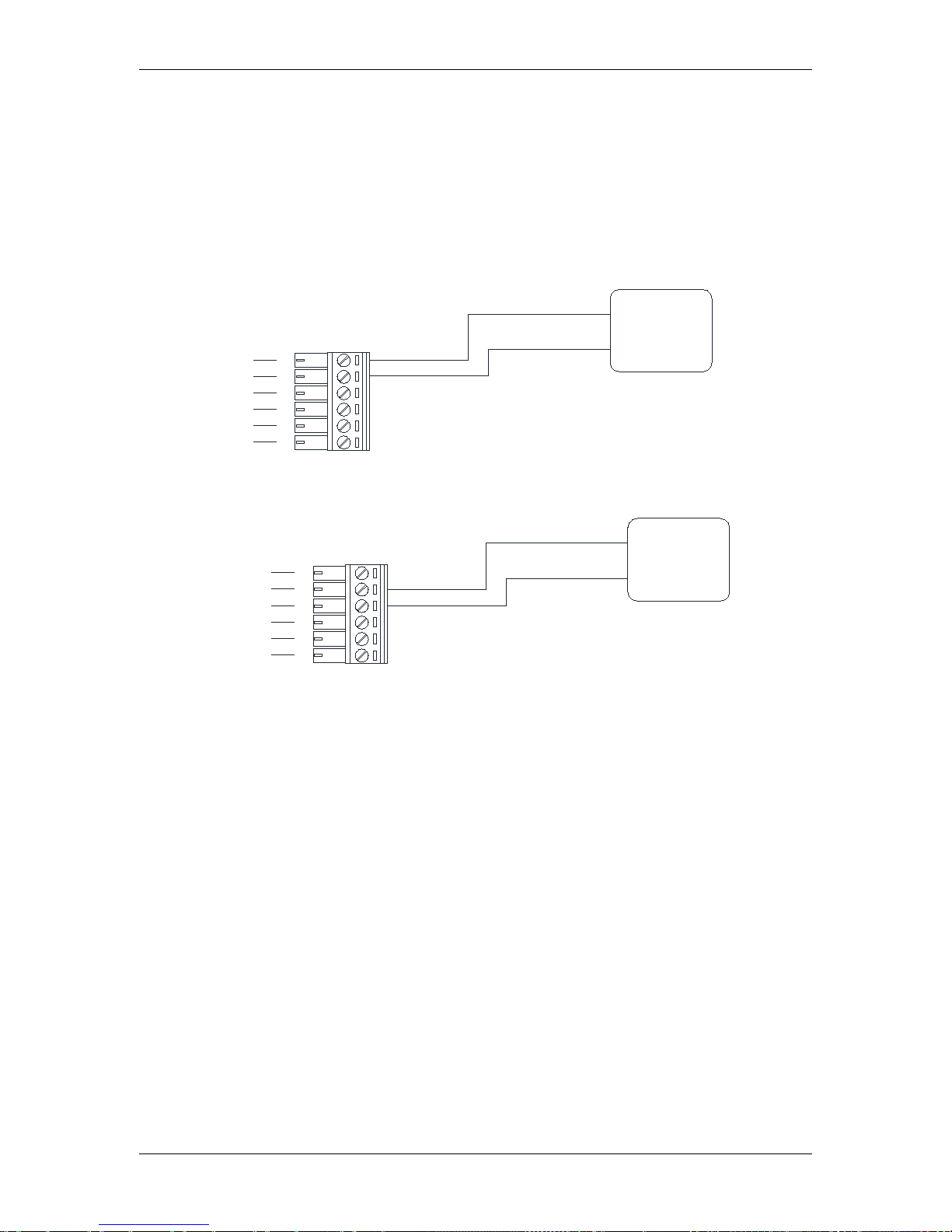
2.4.1 Connecting to an Electric Strike
Connect the Electric Strike to terminals 15-17 on the reader.
Figure 2-3 Example for connecting to an electric strike
2.4.2 Connecting to a Magnetic Lock
Connect the Magnetic Lock to terminals 15-17 on the reader.
Figure 2-4 Example for connecting to a Magnetic Lock
Note:
1. The maximum current outputted by the Door Lock relay on the controller is less than
5A. If the current of the door lock exceeds the capacity, an external power relay is
required.
2. V+ in the figures represents one lead of an external power source. When using DC
voltage, put the positive lead here. When using AC, the leads are interchangeable.
V+
V-
N.C.
COM
16
17
15
COM
N.O.
V-
V+
16
17
15
TCP/IP Network Access Controller
13
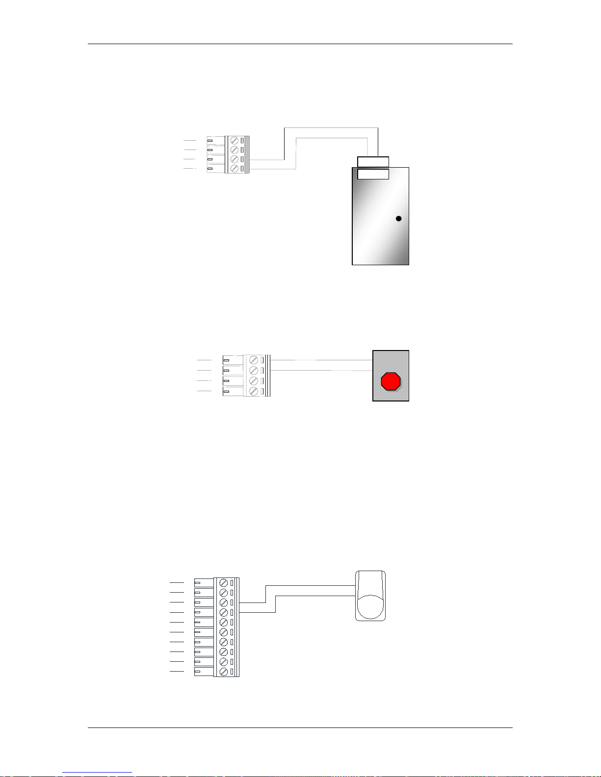
2.5 Connecting to the Door Sensor
The interface to the door sensor is also provided by the controller. Connect the door sensor
to terminals 1 and 2.
Figure 2-5 Example for connecting to the Door Sensor
2.6 Connecting to the Door Button
The interface to the door sensor is also provided by the controller. Connect the door sensor
to terminals 3 and 4.
Figure 2-6 Example for connecting to the Door Button
2.7 Connecting to the Fire Alarm
One fire alarm input is provided. The corresponding terminals are 13 and 14.
2.8 Connecting to the Alarm Input
Other than the fire alarm, 4 alarm inputs are provided. Using the alarm input 1 as an
example, the method to connect the alarm sensor to the alarm input 1 is shown in Figure
2-7:
Figure 2-7 Connecting the alarm sensor to the controller
Alarm sensor
for alarm in 1
Alar m input
GND
8
7
9
10
12
11
13
14
5
6
3 4 2 1 3 4 2
1
Door Sensor
TCP/IP Network Access Controller
14
2.9 Connecting to the Alarm Output
Two alarm outputs are provided. Users can assign the corresponding relay status to the
different events. There are three terminals: COM, N.O. and N.C. The wiring depends on the
alarm device. Please read the user manual of the external alarm devices before wiring.
Using the alarm output 1 as an example, the method to connect the alarm device to the
alarm output 1 is shown in figures below:
Figure 2-8 Connecting to the N.O. alarm device
Figure 2-9 Connecting to the N.C. alarm device
Exteral
Alarming
Device
C.terminal
N.O. terminal
COM
N.O.
21
20
22
23
18
19
N.C.
COM
N.C. terminal
C.terminal
Exteral
Alarming
Device
21
20
22
23
18
19
TCP/IP Network Access Controller
15
3 Connection
3.1 Connecting to the Computer through the TCP/IP
User can carry out basic setting through the keypad on the EFC301F reader or connection
with the computer via TCP/IP. User can carry complicated system administration by
accessing the embedded system in the controller through various browsers.
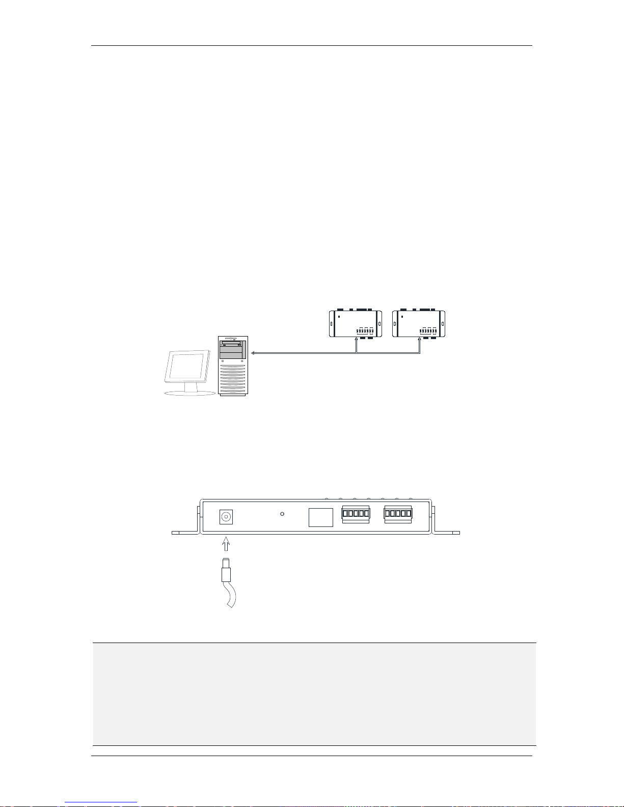
3.2 Connecting to Power
You can power the controller through a specific PoE network switch by connecting a
network cable to the LAN port on the controller, or by connecting a 12 VDC power source to
the power port on the controller.
Figure 3-1 Connecting to power
Note:
1. The voltage range of power source for EFC301F controller is 12 VDC±15%. The
maximum current of the controller is 600mA.
2. The distance from the power supply to the controller should be within 2 meters. In
addition, the electromagnetic lock and alarm equipment must be powered separately
from the controller. The controller can only supply power for controller and readers.
DAT
CT
DCO
G
DAT
RESET
MAINREADER AUX READER
DC IN LAN
CT
T
R
G
DCO
Chapter
3
TCP/IP
POWER
SENSOR1LOCK
3
ALARMIN
2 4
MAIN AUX
1 2FIRE
ALARMOUT
DOORREADER
EverFocus
ControlUnit
NAVAccessController
LNK ACT
NET
P
OW
ER
SENSOR1LOCK
3
ALARMIN
2 4
M
AI
N AUX
1 2FIRE
ALARMOUT
DOORREADER
EverFocus
ControlUnit
NAVAccessController
LNK ACT
NET
Controller Controller

TCP/IP Network Access Controller
16
3.3 Restoring the Controller
To restore the controller to the factory default settings, press the Reset button on the
controller using a paperclip.
Figure 3-2 Reset button on the controller
3.4 Before First Use
Before first use, please follow the instructions below:
1. Set up the IP address, date and time of the controller.
2. Set up the card properties.
3. Set up the alarm signals.
4. Set up the door settings.
5. Set up the date and time period.
RESET
RESET

TCP/IP Network Access Controller
17
4 Operation Instructions of Hardware
EFC301F integrates the card reader function, keystroke operation function, LCD display
function and control function. This chapter mainly introduces the functions of the system
and the relevant operating procedures. The simple settings of the controller can be
conducted through the keyboard and LCD display on the reader, and the operations of other
complex functions need to be controlled through the WEB browser. For details, please refer
to the description in the software chapter.
4.1 Operation Instructions of Keystrokes on the Reader
1 2 3
4 5 6
7 8 9
* 0 #
The 3×4 keyboard on the main card reader is shown in the figure above.
Main Interface
#: System function key
*: Protection setup / withdrawal key
Enter System Menu
#: OK
*: Cancel
“2”、“8”: Up and down movement
“4”: Enter previous menu. If no previous menu is available, return to main interface
“6”: Enter next menu
“5”: Select
Chapter
4
TCP/IP Network Access Controller
18
4.2 Operation of Home Page
After the system is installed, the LCD screen of the reader will display the date, day of the
week and time. This page is called the Home Page and various operations of the controller
will be correspondingly displayed here. After entering the system menu, each time “*” key
is pressed, it will return to the previous menu. In addition, not performing any operation for
1 min or continuously pressed “*”, will make the system automatically return to the Home
Page.
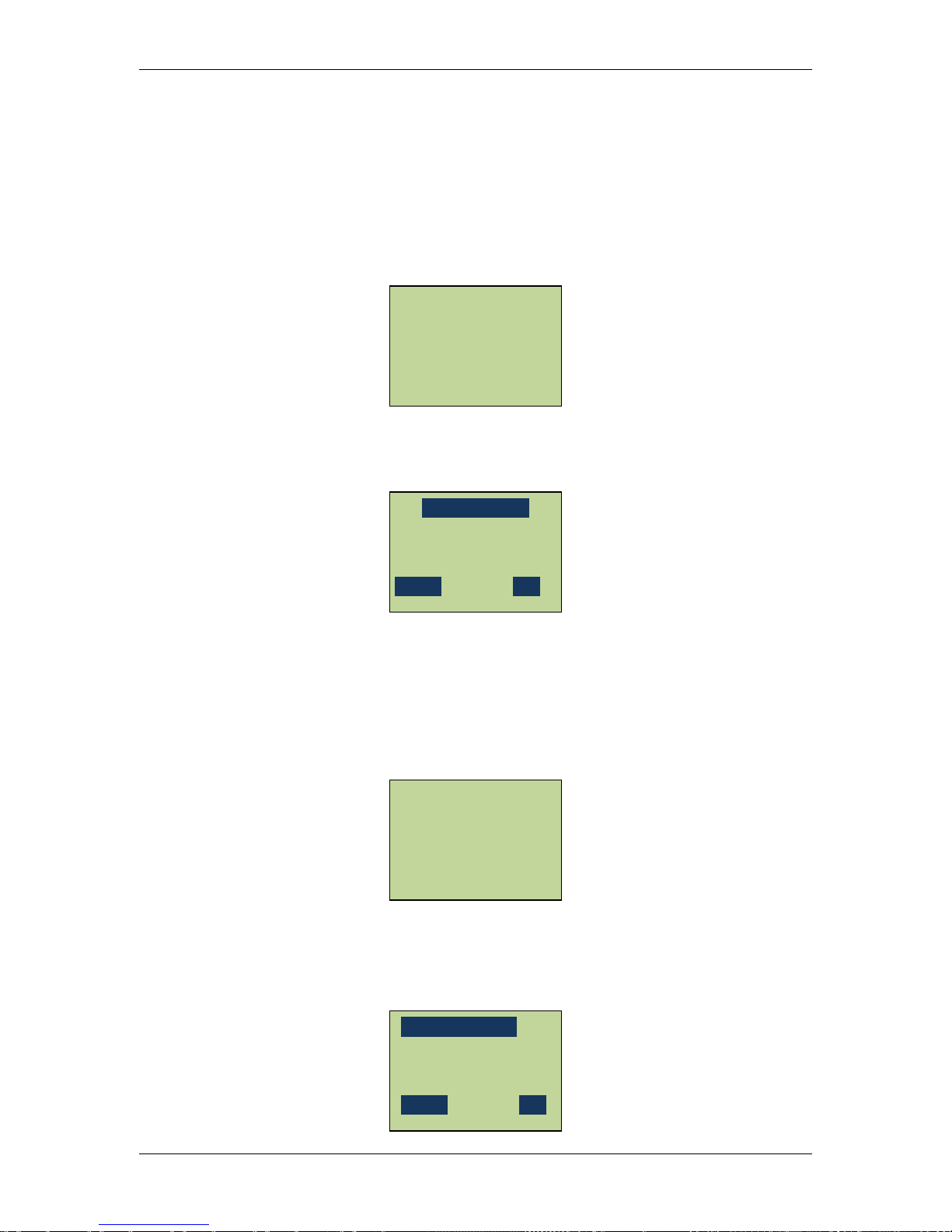
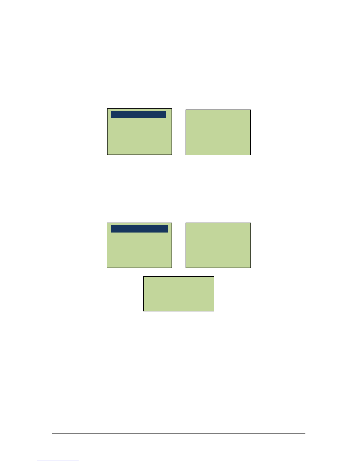
Press system key “#” on the Home Page and the system will request the user to input the
system administration password. See the figure below:
After inputting the system password, press the confirmation key “#” to enter the “System
Setting” menu. The default password of the system is 00000000. For security purposes,
after entering the system for the first time, please change the password as soon as possible
and properly maintain the password. If an incorrect password is entered three consecutive
times, the system will automatically sound the alarm and lock the keyboard for 1 min. Then,
after pressing any key, the following screen will show up:
Press “*” on the main interface of the system and the protection setup / withdrawal
administration. Interface will show up. First, the system requests that the user input the
alarm administration password.
Input ARM PIN
_ _ _ _ _ _ _ _
Cancel OK
2013-01-04
MON 09:38
Keyboard Locked!
Welcome!
Input SYS PIN
_ _ _ _ _ _ _ _
Cancel OK
2013-01-04
MON 09:38
Welcome
TCP/IP Network Access Controller
19
The default password of the system is 00000000. After entering the alarm administration
password, press “#.” If an incorrect password is entered three consecutive times, the system
will automatically sound the alarm and lock the keyboard for 1 min. For security purposes, it
is suggested that the user change the password after entering the system for the first time
and properly secure the password.
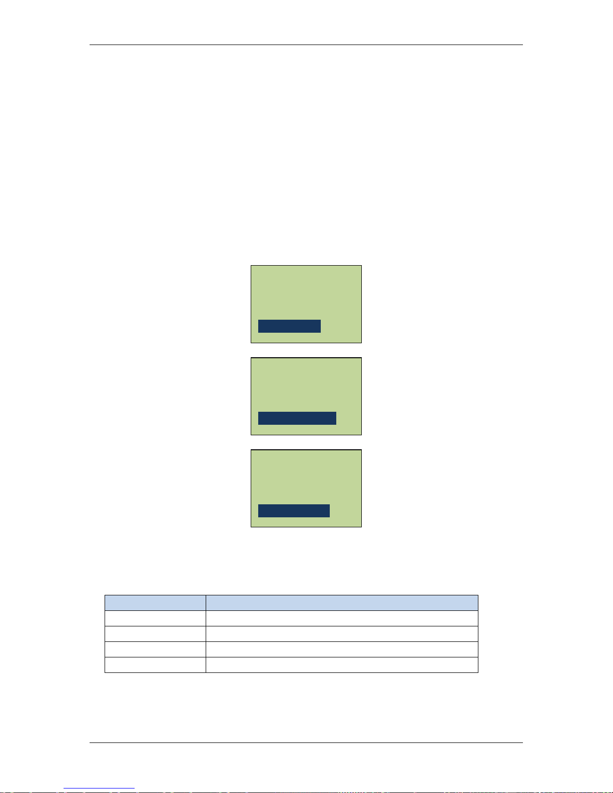
After the protection setup administration authority is successfully verified, enter the
protection setup administration system. If there currently is an alarm input or latched alarm
input, the system will request to reset the alarm. The system will prompt the user to press
“#” to reset the alarm system, carry out protection setup or withdrawal
operation, press “#” to toggle between protection setup and protection
withdrawal and press “*” to exit and save the settings on exit. If carrying out protection
setup operation of the system, after exit, the system will enter protection setup delaying
state.
Under the protection setup operation mode, the Alarm In LED lamp 1-4 on the casing of the
controller will indicate four different states, see Table 4-1:
Table 4-1 States of Indicator Lamp
Yellow LED System Protection State
Off
In protection withdrawal state
On In protection setup state
Slowly blink
In protection setup delaying state
Rapidly blink
In protection setup state, and alarm triggered.
System Armed
[#] To Disarm
System disarmed
[#] to Arm
Alarm Reset?
[#] To Reset
TCP/IP Network Access Controller
20
4.3 Main Menu of System Setting
After entering the System Setting menu, the numerical keys 2 and 8 have up and down
scrolling functions, respectively, the “*” key has the function of returning to the previous
menu or exiting the menu system and the “#” key has the function of confirming entry of
the current highlight menu. The main menu of the System Setting has eight submenu items.
After scrolling to the last menu item, continue rolling downward, it will return to the first
menu item.
4.4 System Setting
In the System Setting main menu, scroll to “System Setting” menu item and press “#” to
enter the “System Setting” menu. In the System Setting menu, there are 11 submenu items
in all. Users can carry out basic setup by selecting the corresponding menu items, such as
date, time, password, etc. After entering the “System Setting” menu, the following screen
will show up:
Roll up and down with the numerical keys 2 and 8 to select the menu items and press “#” to
enter the corresponding setup.
Restore Expired Event
Erase All Events
Restore Factory Setting
Auto Daylight
Set SYS Password
Set ARM Password
Set Backlight
Set Language
Set Date Format
Set Date
Set Time
Alarm Setting
Address Setting
Set Network
System Info
System Setting
Card Setting
Reader Setting
Door Setting

TCP/IP Network Access Controller
21
4.4.1 Set Language
In the “System Setting” menu, scroll to “Set Language” menu item and press “#” to enter
the “Set Language” interfaces.
Scroll to select Chinese, English or Russian, press “5” to select, press “#” to save setting and
exit and press “*” to cancel the setting.
4.4.2 Set Date Format
In the “System Setting” menu, scroll to “Set Date Format” menu item and press “#” to enter
the “Set Date Format” interface.
Users can select two date formats: “MM-DD-YY” or “YY-MM-DD.” The current date format is
displayed on LCD. Press “#” to toggle between the two formats. Press “*” to exit the data
display format setup interface. And return to the “System Setting” menu.
MM-DD-YYYY
[#]to toggle
YYYY-MM-DD
[#]to toggle
Set Language
Set Date Format
Set Date
Set Time
*English
简体中文
pyccknň
Set Language
Set Date Format
Set Date
Set Time
 Loading...