

EverFocus EDVR16D1, EDVR16F2, EDVR9D1, EDVR9F1, EDVR16F1 Instruction Manual
...
Instruction Manual
16/9/4 Channel Digital Video Recorder
EDVR SERIES

EVERFOCUS ELECTRONICS CORPORATION
EDVR SERIES
Instruction Guide
2005 EverFocus Electronics Corp
www.everfocus.com
All rights reserved. No part of the contents of this manual may be reproduced or transmitted
in any form or by any means without written permission of the Everfocus Electronics
Corporation.
Release Date: Oct. 2008

Federal Communication Commission Interference Statement
This equipment has been tested and found to comply with the limits for a Class B digital
device, pursuant to Part 15 of the FCC Rules. These limits are designed to provide
reasonable protection against harmful interference in a residential installation. This
equipment generates, uses and can radiate radio frequency energy and, if not installed
and used in accordance with the instructions, may cause harmful interference to radio
communications. However, there is no guarantee that interference will not occur in a
particular installation. If this equipment does cause harmful interference to radio or
television reception, which can be determined by turning the equipment off and on, the
user is encouraged to try to correct the interference by one of the following measures :
•Reorient or relocate the receiving antenna.
•Increase the separation between the equipment and receiver.
•Connect the equipment into an outlet on a circuit different from that to which the receiver
is connected.
•Consult the dealer or an experienced radio/TV technician for help. FCC Caution: Any
changes or modifications not expressly approved by the party responsible for compliance
could void the users’s authority to operate this equipment. This device complies with Part
15 of the FCC Rules. Operation is subject to the following two conditions: (1) This device
may not cause harmful interference, and (2) this device must accept any interference
received, including interference that may cause undesired operation. This device and its
antenna(s) must not be co-located or operating in conjunction with any other antenna or
transmitter.

CE Declaration
This equipment has been tested and found to comply with the limits for a CE Class A
digital device.
The changes or modifications not expressly approved by the party responsible for
compliance could void the user’s authority to operate the equipment.
In a domestic environment this product may cause radio interference. In which case the
user may be required to take adequate measures.

TABLE OF CONTENTS
1. PRODUCT OVERVIEW ..............................................................................................1
1.1 Features.................................................................................................................1
1.2 Specifications.........................................................................................................2
1.3 Front Panel Keypads .............................................................................................4
1.4 Back Panel Connections........................................................................................7
1.5 Monitor Display....................................................................................................10
2. INSTALLATION.........................................................................................................13
2.1 Packing................................................................................................................13
2.2 System Floorplan.................................................................................................13
2.3 Basic Wiring Instructions......................................................................................14
2.4 Final Install Process.............................................................................................15
3. DVR MENU SETUP ..................................................................................................16
3.1 Time/Date Setup Menu........................................................................................17
3.2 Camera Setup Menu............................................................................................21
3.3 Record Setup Menu.............................................................................................26
3.4 Alarm Setup Menu ...............................................................................................28
3.5 Motion Setup Menu..............................................................................................31
3.6 VIDEOLOSS Setup Menu....................................................................................34
3.7 Network Setup Menu ...........................................................................................36
3.7.1 CONFIG........................................................................................................36
3.7.2 ALARM (NETWORK) ....................................................................................38
3.7.3 EMAIL ...........................................................................................................39
3.7.4 PASSWORD..................................................................................................41
3.7.5 PPPoE...........................................................................................................42
3.7.6 DDNS............................................................................................................43
3.8 Schedule Setup Menu..........................................................................................44
3.9 Disk Setup Menu .................................................................................................46
3.10 Control Setup Menu...........................................................................................48
3.11 Warning Setup Menu..........................................................................................50
3.11.1 FAN FAULT..................................................................................................50
3.11.2 HDD TEMP..................................................................................................51
3.11.3 NO HDD ......................................................................................................53
3.11.4 HDD FULL...................................................................................................54
3.12 System Setup Menu...........................................................................................55
4. RECORDING OVERVIEW........................................................................................59

4.1 Instant (N) Recording Setup ................................................................................59
4.2 Schedule Recording Setup..................................................................................60
4.3 Event Recording Setup........................................................................................60
5. PLAYBACK OVERVIEW...........................................................................................63
5.1 Basic Playback ....................................................................................................63
5.2 Search Playback..................................................................................................65
6. COPYING VIDEO......................................................................................................68
6.1 Viewing a Copied File..........................................................................................70
7. CALL OVERVIEW.....................................................................................................72
8. SCREEN DISPLAY SETTING & MODE....................................................................74
8.1 Mode Button ........................................................................................................76
9. UPGRADE FIRMWARE............................................................................................77
10. NETWORKING OVERVIEW ...................................................................................78
10.1 Introduction to TCP/IP........................................................................................78
10.2 Subnet Masks....................................................................................................78
10.3 Gateway Address...............................................................................................79
10.4 Virtual Ports.......................................................................................................79
10.5 Pre-Installation...................................................................................................80
10.6 What Type of Network Connection do you have?..............................................81
10.7 Simple One to One Connection .........................................................................82
10.8 Direct High Speed Modem Connection..............................................................88
10.9 Router or LAN Connection.................................................................................90
11. LINKSYS PORT FORWARDING ............................................................................93
12. D-LINK PORT FORWARDING ...............................................................................97
13. DDNS....................................................................................................................101
13.1 Creating a DDNS Account...............................................................................101
14. VIEWING THROUGH INTERNET EXPLORER ....................................................103
14.1 Search .............................................................................................................107
14.1.1 Search by TIME.........................................................................................107
14.1.2 Search by EVENT.....................................................................................108
14.2 PTZ control......................................................................................................109
14.3 Remote Archive ............................................................................................... 111
14.4 Remote Configuration......................................................................................116
APPENDIX A: REMOTE CONTROL ..........................................................................123

APPENDIX B: ALARM BOARD CONFIGURATION ..................................................124
APPENDIX C: RJ45 (RS485) PIN ASSIGNMENT......................................................127
APPENDIX D: LAPSE MODE RECORDING TABLE.................................................128
APPENDIX E: INSTALLATION STEPS OF NERO INCD SOFTWARE......................132
APPENDIX F: SATA BOARD INSTALLATION...........................................................141
INDEX .........................................................................................................................143
TROUBLESHOOTING................................................................................................145

Safety Warning
WARNING
To reduce risk of fire or electric shock, do not expose this appliance to
rain or moisture.
CAUTION
Do not remove cover. No user serviceable parts inside. Refer
servicing to qualified service personnel.
Note:
This equipment has been tested and found to comply with the limits
for a Class A digital device,
The changes or modifications not expressly approved by the party
responsible for compliance could void the user's authority to operate
the equipment.
Note:
This is a class A product. In a domestic environment this product may
cause radio interference
In which case the user may be required to take adequate measures.
Notice:
The information in this manual was current when published.
The manufacturer reserves the right to revise and improve its products.
All specifications are therefore subject to change without notice.
CAUTION
Risk of explosion if battery is replaced by an incorrect type.
Dispose of used batteries according to the instructions.

Safety Precautions
Refer all work related to the installation of this product to qualified service
personnel or system installers.
Do not block the ventilation opening or slots on the cover.
Do not drop metallic parts through slots. This could permanently damage the
appliance. Turn the power off immediately and contact qualified service
personnel for service.
Do not attempt to disassemble the appliance. To prevent electric shock, do not
remove screws or covers. There are no user-serviceable parts inside. Contact
qualified service personnel for maintenance. Handle the appliance with care.
Do not strike or shake, as this may damage the appliance.
Do not expose the appliance to water or moisture, not try to operate it in wet
areas. Do take immediate action if the appliance becomes wet. Turn the power
off and refer servicing to qualified service personnel. Moisture may damage
the appliance and also cause electric shock.
Do not use strong or abrasive detergents when cleaning the appliance body.
Use a dry cloth to clean the appliance when it is dirty. When the dirt is hard to
remove, use a mild detergent and wipe gently.
Do not overload outlets and extension cords as this may result in a risk of fire
or electric shock.
Do not operate the appliance beyond its specified temperature, humidity or
power source ratings. Do not use the appliance in an extreme environment
where high temperature or high humidity exists. Use the appliance at
temperature within indoor type DVR for 0°C~40°C (32 °F~104°F) and a
humidity between 20%~80%. The input power source for this appliance is
100~240VAC.

Safety Precautions
Read Instruction
All the safety and operating instructions should be read before the unit is
operated.
Retain Instructions
The safety and operating instructions should be retained for future reference.
Heed Warnings
All warnings on the unit and in the operating instructions should be adhered to.
Follow Instructions
All operating and use instructions should be followed.
Cleaning
Unplug the unit from the outlet before cleaning. Do not use liquid cleaners or
aerosol cleaners. Use a damp cloth for cleaning
Attachments
Do not use attachment not recommended by the product manufacturer as they
may cause hazards.
Water and Moisture
Do not use this unit near water-for example, near a bath tub, wash bowl, kitchen
sink, or laundry tub, in a wet basement, near a swimming pool, in an unprotected
outdoor installation, or any area which is classified as a wet location.
Servicing
Do not attempt to service this unit by yourself as opening or removing covers
may expose you to dangerous voltage or other hazards. Refer all servicing to
qualified service personnel.
Power Cord Protection
Power supply cords should be routed so that they are not likely to be walked on
or pinched by items placed upon or against them, playing particular attention to
cords and plugs, convenience receptacles, and the point where they exit from
the appliance.
Object and Liquid Entry
Never push objects of any kind into this unit through openings as they may touch
dangerous voltage points or short-out parts that could result in a fire or electric
shock. Never spill liquid of any kind on the unit.

1111
1. Product Overview
The latest EverFocus digital video recorder generation is based on MPEG-4
compression technology, resulting in enhanced recording capacity and improved
network image transmission speed with high image quality. Comprehensive features
and extended event recording settings enable the almost universal application of this
DVR series.
11..11 FFeeaattuurreess
Pentaplex Operation (Live, Recording, Playback, Archiving, Remote Viewing)
Built-in MPEG4 Codec with Configurable Quality
Composite and VGA main outputs
EDVR16D1/F1, EDVR9D1/F1, EDVR4D1/F1: Variable Recording Speeds Up to
120/100(CIF) Pictures per second for NTSC/PAL
EDVR16D2/F2: Variable Recording Speeds Up to 240/200(CIF) Pictures per
second for NTSC/PAL
EDVR16D3: Variable Recording Speeds Up to 480/400 (CIF) Pictures per second
for NTSC/PAL
Audio Recording capabilities
2 way audio supported
Multiple Motion Detection Capabilities for each camera (28*22)
Support RS485 for PTZ and/or control keyboard
Built-in real time clock and Auto Time Synchronization with global NTP server
through Internet
F Serial (without DVD): Built-in up to Four 3.5” IDE Hard Disks can be added
D Serial (with DVD RW): Built-in up to Two 3.5” IDE Hard Disks can be added
Note: If you use SATA Hard Disk, a SATA board is an optional accessory to be purchased.
Please see Appendix F for SATA Hard Disk installation steps.
Ethernet Interface for Remote Network Viewing and Controlling
Shuttle/Jog Dial for Picture-by-Picture or Fast/Slow Viewing
Easy-to-use User Friendly Control via Front panel keypad, Shuttle/Jog, IR remote
controller (optional), and Control Keyboard (optional)
On-Screen Menus Operations with Multi-Language Support
Real-Time Live Display for all Cameras
2 USB 2.0 Interface, one for archiving and the other one for mouse usage
Support external DVD+RW for archiving
D Serial (with DVD RW): built-in DVD+RW for video clip exporting
Water Mark Capabilities helps to identify purposely modification of recorded data
USB2.0 port for video clip exporting, supports USB thumb drive
Chapter
1

2222
Free DDNS server for use with dynamic IP addresses
Remote configuration function
Remote Firmware Upgrade function
System diagnostic feature alerts users of HDD or system problems via Email or
alarm output
11..22 SSppeecciiffiiccaattiioonnss
Video Format NTSC or PAL
Operating System Embedded Linux
Video Input 16/9/4 camera inputs, BNC 1.0Vp-p, 75ohm
Video Output
1 Video Output for Main Monitor, BNC 1.0Vp-p, 75ohm
1 Video Output for Call Monitor, BNC 1.0Vp-p, 75ohm
1 VGA Output
16/9/4 Video Outputs for Looping, BNC 1.0Vp-p, 75ohm
Video Compression MPEG4
Video Resolution
Selectable
D1/F1
NTSC: 360X240(120IPS), 720X240(60IPS), 720X480(30IPS)
PAL: 360X288(100IPS), 720X288(50IPS), 720X576(25IPS)
D2/F2
NTSC: 360X240(240IPS), 720X240(120IPS), 720X480(60IPS)
PAL: 360X288(200IPS), 720X288(100IPS), 720X576(50IPS)
D3
NTSC: 360X240(480IPS), 720X240(240IPS), 720X480(120IPS)
PAL: 360X288(400IPS), 720X288(200IPS), 720X576(100IPS)
Video Display
Full, PIP(Live only), 4, 7, 9, 10, 13, 16 and 2X2 Zoom for Live and
Playback
Display Resolution 720X480 (NTSC) or 720X576 (PAL)
Video Pause Yes
Alarm Input 16/9/4 Alarm Inputs
Alarm Output 1 Alarm Output(D3:4 Alarm Outputs)
Hard Disk Storage 2 Internal 3.5" IDE Hard Disk
Recording Rate
D1/F1: Up to 120 IPS(360X240) for NTSC / Up to 100
IPS(360X288) for PAL
D2/F2: Up to 240 IPS(360X240) for NTSC / Up to 200
IPS(360X288) for PAL

3333
D3/F3: Up to 480 IPS(360X240) for NTSC / Up to 400
IPS(360X288) for PAL
Recording Mode
Continue, Time-lapse, Schedule or Event Recording (Motion,
Alarm)
Play Search By Date/Time or Event
Motion Detection
Yes,
with Multiple configurable detection areas (28X22) & 10 levels
of sensitivity
Video Loss Detection Yes
Event Log Yes
User Interface User friendly OSD Menu Driven
Setup On screen display setup
User Input Device
Front Panel Keypad with Shuttle/Jog, Keyboard(Optional), IR
remote Control, Mouse
Timer
Built-in real time clock and Auto Time Synchronization with global
NTP Server through Internet
Watch Dog Timer Yes
Title 12-characters title for each camera
Ethernet RJ-45 connector for network communications, 10/100Mbs
Archive 2 USB2.0, DVD RW (D series only); Internet Transmission
RS-232 9-pin female connector for local communication
RS-485 For control Keyboard or PTZ connection
Audio
4 mono (MIC) input for Ch1, 2, 3, 4
1 mono (Speaker) output from Ch1
Power Source 100VAC~240VAC
Power Consumption
240VAC, 65W Max
100VAC, 52W Max
Dimensions 402(L) X 430(W) X 72(H) mm ; 15.8"(L) X 16.9"(W) X 2.8"(H)
Weight 6.42kg ; 14.2lbs
Operating Temperature
0℃~40℃ ; 32oF ~ 104oF (20%~80% Humidity)
4444
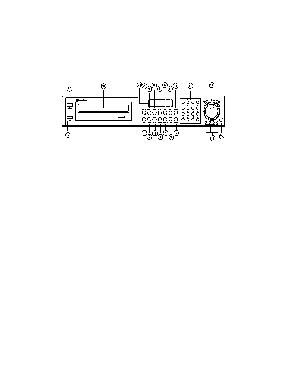
11..33 FFrroonntt PPaanneell KKeeyyppaaddss
Keys:
1
REC
Press this key to start instant recording.
2
STOP
Press this key to stop recording and playing back.
3
PLAY
Play Back.
4
PAUSE
Press this key to pause the playback picture.
5
SEARCH
Press this key to enter the SEARCH MENU.
6
COPY
Opens image export menu. In playback mode, the current playback position is
stored as image export start position.
7
ENTER
Press this key to enter items, or jump to next subentry in the menu setting.
8
DISPLAY
Press this key to switch display of channels, display color of channels (Black, Red,
Yellow, Pink, Blue and White are available as choices) and/or status bar.
5555
9
SELECT
On live view, press this key to assign a camera to a multi-screen or to adjust single
screen display properties. In menus, press this key to select certain features.
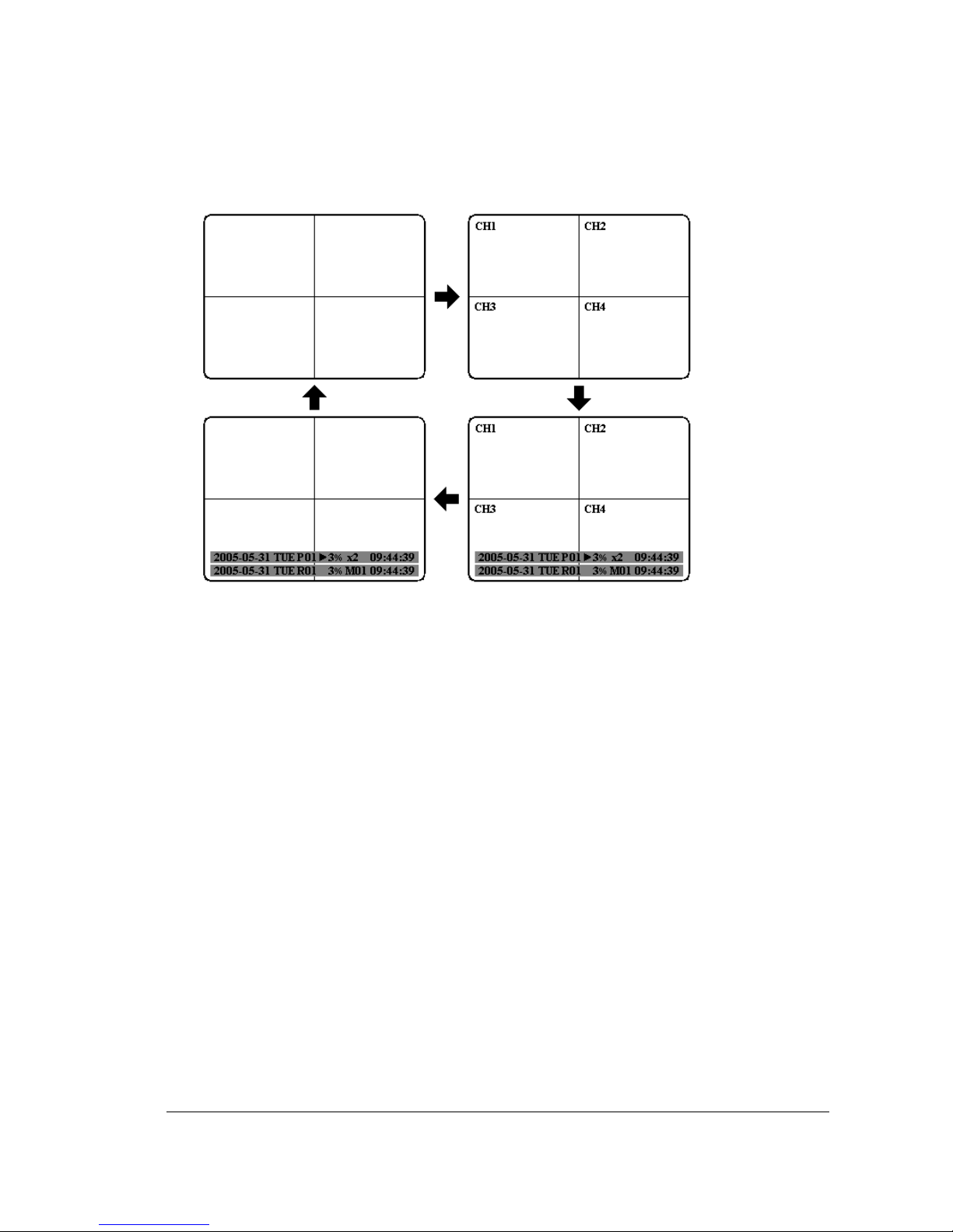
10
MODE
Switch PIP, 4, 7, 9, 10, 13 and 16 displays in Live and Playback modes.
11
ZOOM
In full screen mode, 2x electronic zoom. Zoom screen can be moved through JOG.
Enter key changes the direction. Pressing the zoom key again switches the
electronic zoom off.
In multiscreen mode: Image orientation adjustment. Use the JOG to adjust the
image to the respective monitor type. ENTER switches between horizontal and
vertical adjustment. Press the zoom key again to exit screen adjustment.
12
SEQ
Press this key to enter the auto sequential switching mode.

6666
13
CALL
Press this key to enter and set up CALL MENU.
14
Menu
Press this key to enter MAIN SETUP MENU or to exit from any submenu.
15
Shuttle and Jog Dial
Shuttle:
In the Playback mode, turn the Shuttle dial to fast
forward/rewind the video.
In the Pause mode, turn the Shuttle dial to slow
forward/rewind the video.
In the event list, turn the Shuttle to change pages.
Jog Dial:
In the Pause mode, turn the Jog dial to forward/rewind the
video frame by frame. In the Menu mode, turn the Jog dial to
change settings and values in subentries.
16
System LEDs
LEDs for system active HDD, ALARM and LAN display.
Note: External HDD LED will only be light on for EDVR16D3 model.
17
Channel Key (1~16)
Press channel key (CH1~CH16) to display that channel in full screen view.
18
Mouse
For connecting the mouse.
19
DVD+RW Burner
DVD+RW burner (only available for D series).
20
USB Slot
USB port allows you to archive files into your storages.
21
LCD Panel
To display Date and Time, and other system information.
22
IR receiver
Receiver for optional infrared remote control.
7777
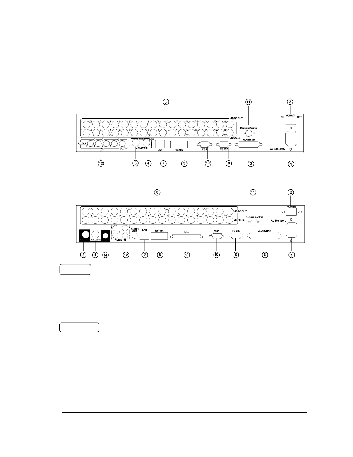
11..44 BBaacckk PPaanneell CCoonnnneeccttiioonnss
1
Main Power plug
Connect power jack (AC 100~240V).
2
Power Switch
Switch DVR on or off.
3
MAIN MONITOR
This connector is used for the main monitor display, a number of different display
modes may be selected for viewing.
4
CALL MONITOR
This connector is used for the call monitor. This monitor can only display a full
screen, but not able to enter Setup Menu.
POWER
MONITOR
For models:
EDVR16D1/F1, EDVR16D2/F2,
EDVR9D1/F1, EDVR4D1/F1
For model:
EDVRD3

8888
VIDEO IN
5
16 CH:
VIDEO OUT (1~16): BNC connectors for video looping out 1~16.
VIDEO IN (1~16): BNC connectors for video input 1~16.
9 CH:
VIDEO OUT (1~9): BNC connectors for video looping out 1~9.
VIDEO IN (1~9): BNC connectors for video input 1~9.
4 CH:
VIDEO OUT (1~4): BNC connectors for video looping out 1~4.
VIDEO IN (1~4): BNC connectors for video input 1~4.
ALARM INPUT/OUTPUT
6
ALM-INPUT
Normal open or normal close type alarm signal inputs.
The Alarm Input can be selected as normal open (N.O.) or normal close (N.C.) input
in the ALARM SETUP MENU. When an alarm occurs, alarm recording will
automatically start.
ALM-OUTPUT: A built-in relay offers 3 nodes which are ALM-COM (common),
ALM-NO (normal open) and ALM-NC (normal close) for external use.
Note: Please check APPENDIX B to see other available alarm input/output
functions.
LAN
7
LAN Connector
The RJ-45 LAN connector.
RS232
8
RS232 connector
9-pin Sub-D control input/output for service purpose.
RS485
9
RS485 connector
RJ 45 Connector to cascade/control multiple Digital Video Recorders.

9999
VGA
10
VGA
Connect to the monitor that has VGA input.
REMOTE CONTROL (extension cable is optional)
11
Remote Control
Connector for IR extension cable that has an IR remote control receiver.
AUDIO
12
Audio IN
Audio inputs 1~4 for recording, and it can be enabled by setting to “YES” or “NO” in
the RECORD SETUP MENU.
Audio OUT
Connect an audio output to a monitor or other device. Audio 1 corresponds to CH 1,
audio 2 corresponds to CH 2, audio 3 corresponds to CH 3 and audio 4 corresponds
to CH 4.
SCSI (Only available for EDVR16D3)
13
SCSI Connector
For connecting the optional external hard drive array (EDA800).
S-VIDEO (Only available for EDVR16D3)
14
S-Video
Provides S-Video connector.
10
1010
10
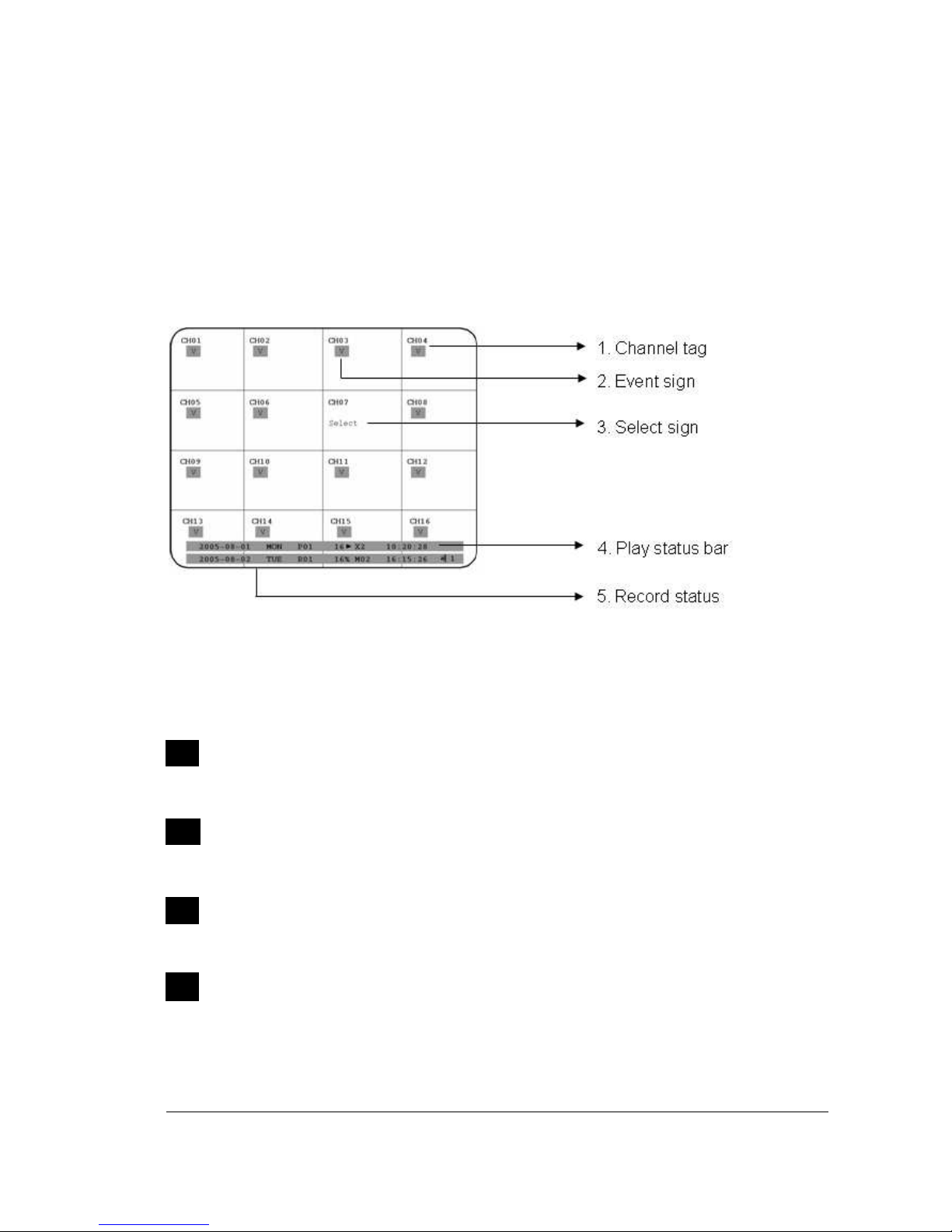
11..55 MMoonniittoorr DDiissppllaayy
The status information of the cameras or machine will show up, and be located at
different places on the screen.
1
. Channel tag
A channel tag indicates the channel name of the screen.
2
. Event sign
Event signals which are small icons with a capital letter and red background show
the events on each screen. There are a total of 6 different signals:
Alarm event.
Alarm event shows on a channel if an ALARM is enabled for that camera in the
ALARM SETUP MENU and an alarm is triggered.
Motion event.
Motion event only shows up when the camera’s MOTION is enabled in MOTION
SETUP MENU and the camera detects movement.
Video loss event.
Video loss event only shows when the camera’s VIDEOLOSS is enabled in
VIDEOLOSS SETUP MENU and the camera signal is lost.
Sequence sign.
Sequence sign shows up when the display is in sequence mode.
S

11
1111
11
The last display on the screen has a “*” sign in the top-middle. The sign will replace
the “*” in the display when sequence occurs.
Note: Sequence is invalid when the multi-screen display is showing all cameras.
Temperature indication.
This shows if the hard drive’s temperature is overheated.
Overheat temperature is determined in HDD TEMPERATURE of WARNING
SETUP MENU.
Fan fail indication.
This shows when the fan fails to work normally. If you get this warning, contact
technical support for assistance.
3
. Select sign: You can assign a camera to a display by pressing SELECT key in live
mode. Dial Jog to move the select sign to the display you would like to change camera,
and then press channel key on the front panel to choose that channel. Press SELECT
again to exit from this mode.
4
. Play status bar: The play status bar appears in play back mode if you enable a
status bar on the screen (Please see DISPLAY, 8th item of Front Panel Keypads).
There are three parts that will be shown: play date, play status, and play time.
1. Play date
The date on which the video was recorded.
2. Play status
“PAUSE”, when the video playback is paused.
“P## >” means normal play speed on the displayed disk number;
“P## <“ means normal reverse play speed on the displayed disk number;
“>> x N” means N time fast play speed;
“<< x N” means N time fast reverse play speed.
3. Play time
The play time at which the video is recorded. The time format depends on the
time format setting in the TIME/DATE SETUP MENU.
Play Date Play Status Play Time
S

12
1212
12
4. Record status bar
The record status bar appears when you enable a status bar on the screen.
There are four parts: current date, record status, event, and current time.
1. Current date
The current date which is set in the TIME/DATE SETUP MENU.
2. Record status
While the unit is recording, current HDD and percentage is displayed.
e.g: “R01 16%”: currently recording on HDD 1, 16% full.
3. Event
The current/last event that occurred.
4. Current time
The current time which is set in the TIME/DATE SETUP MENU.
5. Audio Ch
Displays which audio channel is currently active. This can be changed by
turning the Jog wheel in the live camera mode.
6. HDD/Fan status
“No Disk”: only shows when no disk is installed or detected.
“No Fan”: only shows when internal fan stops working.
“HDD OT”: only shows if hard drive is over temperature.
Current Date
Record Status
Event
Current Time
Audio Ch
HDD/Fan Status
13
1313
13
2. Installation
The installations described below should be done by qualified service personnel or
system installers.
22..11 PPaacckkiinngg
Please check accessories in the packing before installation.
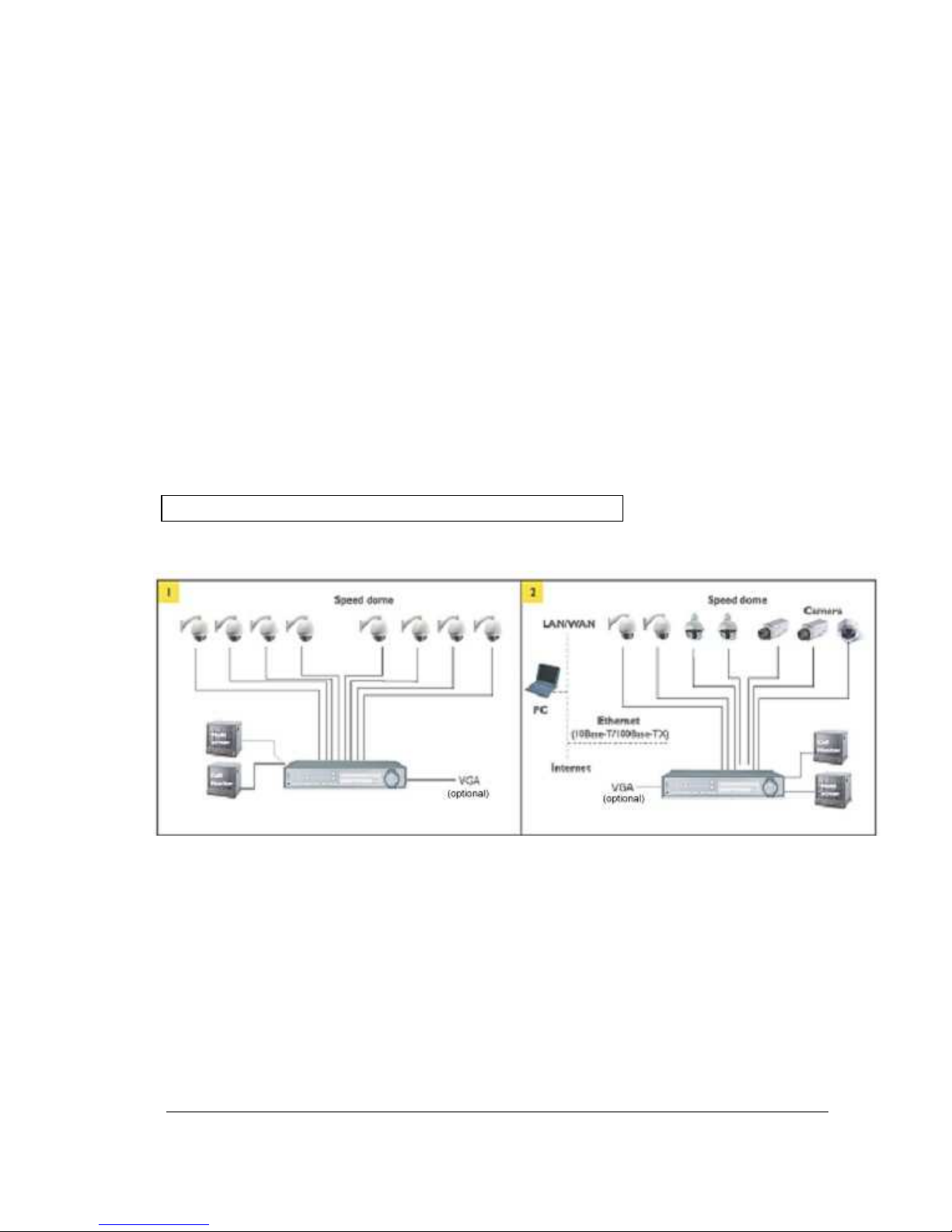
22..22 SSyysstteemm FFlloooorrppllaann
Please refer to the following diagrams for the system connections.
Note: Monitor and Camera must be purchased separately.
Diagram 2.1
Chapter
2

14
1414
14
22..33 BBaassiicc WWiirriinngg IInnssttrruuccttiioonnss
1. Power
Connect the power source or adapter into the power socket.
2. Cameras
Connect each cameras video output to the video input on the digital video recorder
shown in diagram 2.1.
Note: At least one camera (CH 1) must be connected before the system is running for
the auto detection of video standard to take effect.
3. Audio Input
The camera audio output or Microphone is connected to the audio input terminal at the
rear panel.
4. Audio Output
Connect the speaker or other audio listening devices to the audio output terminal on the
back of the digital video recorder.
5. Ethernet
The digital video recorder may be viewed from a PC via the LAN connector using a RJ45
Ethernet cable.
6. RS232
9-pin Sub-D control input/output for service purpose.
7. RS485
The digital video recorder can be controlled from a keyboard or a speed dome via
RS485.
Note: This can be done using a serial cable.
8. Main Monitor
Connect the main monitor output connector to a main monitor. The main monitor
displays selected live or recorded cameras in any available format.
Note: The main monitor must be connected in order to make configuration changes,
enter the main menu, or do a playback at the machine.

15
1515
15
9. Call Monitors
Connect the call monitor output connectors to a call monitor. The call monitor display
selected live cameras in full screen format.
Note: The call monitor will only display one full screen camera at a time.
22..44 FFiinnaall IInnssttaallll PPrroocceessss
Once you have completed the basic wiring installation and the hard disk drive installation
you are ready to turn on the DVR. Simply plug the power source you installed earlier. The
POWER LED lights will light up if power is normal. The next step is to set up the menu
options for the DVR.
16
1616
16
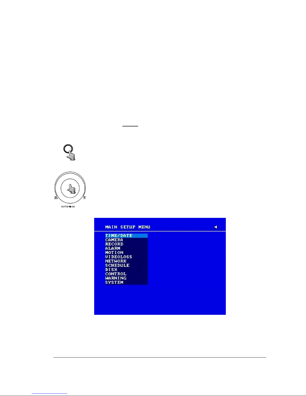
3. DVR Menu Setup
Assuming you have completed the first two chapters of this manual. You are now ready to
begin setting up the digital video recorder. The following chapter will walk you through the
detailed DVR Menu step by step and how to set the DVR for your specific application. To
begin this process, press the MENU key. Once inside the main menu you will find there are
12 setup option pages as follows.
Press the MENU key to enter or exit the MAIN SETUP MENU.
Press the MENU key in any sub-menu to go back to previous screen.
Dial the Jog clockwise or counterclockwise to scroll through the MAIN
MENU options or to change subentry values.
Press the ENTER key to go to the next subentry in a menu setting.
Press the CALL key to go to the previous subentry in a menu setting.
Diagram 3.1
Chapter
3
MENU
17
1717
17
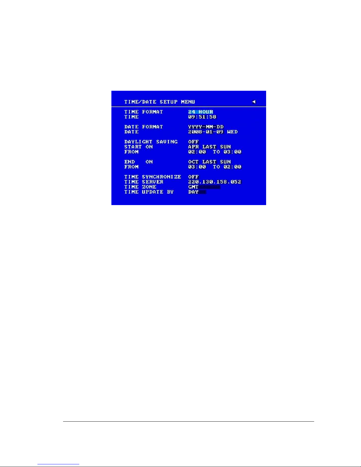
33..11 TTiimmee//DDaattee SSeettuupp MMeennuu
Diagram 3.2
Diagram 3.2 is a screen shot of the TIME/DATE SETUP MENU. This menu is used to set up
the correct time and date for your region of the world. You are able to setup daylight savings
as well as synch it with an internet based time server.
In the TIME/DATE SETUP MENU the following fields are defined as follows:
1. TIME FORMAT
This field represents the time format on the DVR. You can select between 12 HOUR and
24 HOUR format.
2. TIME
This field represents the current time on the DVR. To change this, simply use the Jog
Dial on the DVR.
The Time is represented as follows:
Hour: 00~23 (1 ~ 12 if TIME FORMAT is 12 HOUR); Minute: 00~59; Second: 00~59

18
1818
18
3. DATE FORMAT
This field represents the date format on the DVR. To change this, simply use the Jog Dial
on the DVR. There are three date formats to select from: YYYY-MM-DD, MM-DD-YYYY
and DD-MM-YYYY.
4. DATE
This field represents the date on the DVR. To change this, simply use the Jog Dial on the
DVR.
The date is represented as follows:
Year: 2000~2037 / Month: 01~12 / Date: 01~31 (Day of Week)
5. DAYLIGHT SAVING
This field represents the daylight savings on the DVR. To change this, simply use the Jog
Dial on the DVR. Select “ON” or “OFF” to enable or disable daylight saving time function.
In order to set a daylight saving time zone, you need to disable daylight saving first.
Enable the daylight saving after finish setting the time zone.
Note: Please double-check your current Time on DVR again after setting Daylight
Saving ON. If you are currently in daylight saving time period, then Daylight saving time
may be over-adjusted, as DVR will adjust daylight saving time even though you have
already set the current time which is daylight saving time.
6. START TIME
To set the start time of daylight saving time.
LAST
To set the start week of daylight saving time: Dial the jog to set the start week.
1 ST
2 ND
3 RD
4 TH
THU
SUN
TUE
MON
WED
SAT
To set the start month of daylight saving time: Dial the jog to set the start month.
FEB
MAR
JAN
APR
MAY
JUN
DEC
NOV
OCT
SEP
AUG
JUL
FRI
To set the start date of daylight saving time: Dial the jog to set the start date.

19
1919
19
8. TIME SYNCHRONIZE
Select “ON” or “OFF” to enable or disable time synchronize, which will update the correct
time automatically when network is connected. To change this, simply use the Jog Dial
on the DVR.
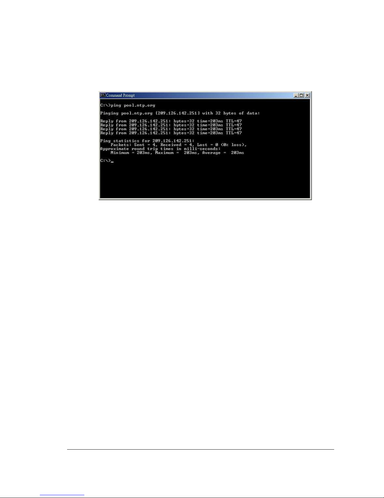
9. TIME SERVER
You can set the time server address that the DVR connects to for time synchronize. To
find the IP address of NTP Server, please follow these steps:
a) Go to a PC that is connected to the internet.
b) Click on “START” -> “RUN” -> type “cmd” and press “OK”.
To set the starting time change of daylight saving time: Choose the “FROM” time
and “TO” time when daylight savings starts.
7. END TIME
To set the end time of daylight saving time.
To set the ending time change of daylight saving time: Choose the “FROM” time
and “TO” time when daylight savings ends.
To set the end week of daylight saving time: Dial the jog to set the end week.
To set the end date of daylight saving time: Dial the jog to set the end date.
To set the end month of daylight saving time: Dial the jog to set the end month.
FEB
MAR
JAN
APR
MAY
JUN
DEC
NOV
OCT
SEP
AUG
JUL
LAST
1 ST
2 ND
3 RD
4 TH
THU
SUN
TUE
MON
WED
SAT
FRI
20
2020
20
c) In the Dos Prompt, type “ping pool.ntp.org” to find out the IP address of an NTP
Server.
Diagram 3.3
10. TIME ZONE
You can set the time zone that the DVR adjusts to when updating from the time
server.
Atlantic Daylight Time subtract 3 hours from GMT
Atlantic Standard Time subtract 4 hours from GMT
Eastern Daylight Time subtract 4 hours from GMT
Eastern Standard Time subtract 5 hours from GMT
Central Daylight Time subtract 5 hours from GMT
Central Standard Time subtract 6 hours from GMT
Mountain Daylight Time subtract 6 hours from GMT
Mountain Standard Time subtract 7 hours from GMT
Pacific Daylight Time subtract 7 hours from GMT
Pacific Standard Time subtract 8 hours from GMT
Alaska Daylight Time subtract 8 hours from GMT
Alaska Standard Time subtract 9 hours from GMT
Hawaii-Aleutian Daylight Time subtract 9 hours from GMT
Hawaii-Aleutian Standard Time subtract 10 hours from GMT
11. TIME UPDATE BY
Once you enable the TIME SYNCHRONIZE, you can select the synchronization
frequency by:
 Loading...