

Page 1
Instruction Manual
Volume
1
E
E
D
D
S
S
R
R
4
4
0
0
0
0
H
H
Page 2

EVERFOCUS ELECTRONICS CORPORATION
EDSR 400h Instruction Guide
© 2004 Everfocus Electronics Corp
2445 Huntington Drive
Phone 626.844.8888 • Fax 626.844.8838
All rights reserved. No part of the contents of this manual may be reproduced or transmitted in any
form or by any means without written permission of the Everfocus Electronics Corporation.
QuickTime is a registered trademark of the Apple Computer, Inc. Windows is a registered trademark
of the Microsoft Corporation in the United States and other countries. Linksys is a registered
trademark of the Linksys Corporation. D-Link is a registered trademark of the D-Link Corporation.
DynDNS is a registered trademark of the DynDNS.org Corporation. Other product and company
names mentioned herein may be the trademarks of their respective owners.
Page 3

Table of Contents
Introduction I
CHAPTER 1
Product Overview 1
Features 1
Specifications 2
Front Panel Keys 3
Back Panel Keys 5
CHAPTER 2
Installation 8
Basic Wiring Instructions 9
Hard Disk Drive Installation 10
Final Install Process 10
CHAPTER 4
Recording Overview 40
Basic Recording Setup 40
Timer Recording Setup 41
Motion Recording Setup 42
Alarm Recording Setup 43
CHAPTER 5
Playback Overview 45
Basic Playback 45
Search Playback 46
Segment List Playback 46
Alarm List Playback 47
Date/Time Playback 48
CHAPTER 3
DVR Menu Setup 11
Clock/Language Setting Menu 12
Title Setting Menu 14
Daylight Setting Menu 15
Timer Setting Menu 17
Normal Record Setting Menu 19
Alarm Record Setting Menu 21
Buzzer Setting Menu 24
Archive Setting Menu 26
Network Setting Menu 28
Sequence Setting Menu 30
RS232/RS485 Setting Menu 32
Motion Setting Menu 35
System Setting Menu 38
CHAPTER 6
Copying Video 50
Still Image Copy 50
Copy as a MOV File 51
Other Archiving Methods 52
Viewing Copied Files 52
CHAPTER 7
Audio Overview 53
CHAPTER 8
How to Upgrade Firmware? 54
CHAPTER 9
Networking Overview 56
Introduction to TCP/IP 56
Subnet Masks 56
Page 4

Gateway Address 57
Virtual Ports 57
Pre-Installation 58
What type of Network Connection 59
Simple One to One Connection 60
Direct High Speed Modem Connection 66
Router or LAN Connection 68
CHAPTER 10
Linksys Port Forwarding 71
Dynamic DNS 75
CHAPTER 13
Viewing through Internet Explorer 85
CHAPTER 14
Interface Specifications 89
Transmission Setting 90
Remote Control Protocol 90
APPENDIX A
Remote Control 93
CHAPTER 11
D-Link Port Forwarding 77
Dynamic DNS 80
CHAPTER 12
DDNS 82
Creating a DDNS Account 82
APPENDIX B
Time Lapse Recording Time 94
APPENDIX C
Alarm Board Configuration 96
TROUBLESHOOTING
Troubleshooting 99
Page 5

EVERFOCUS ELECTRONICS CORPORATION
Chapter
1
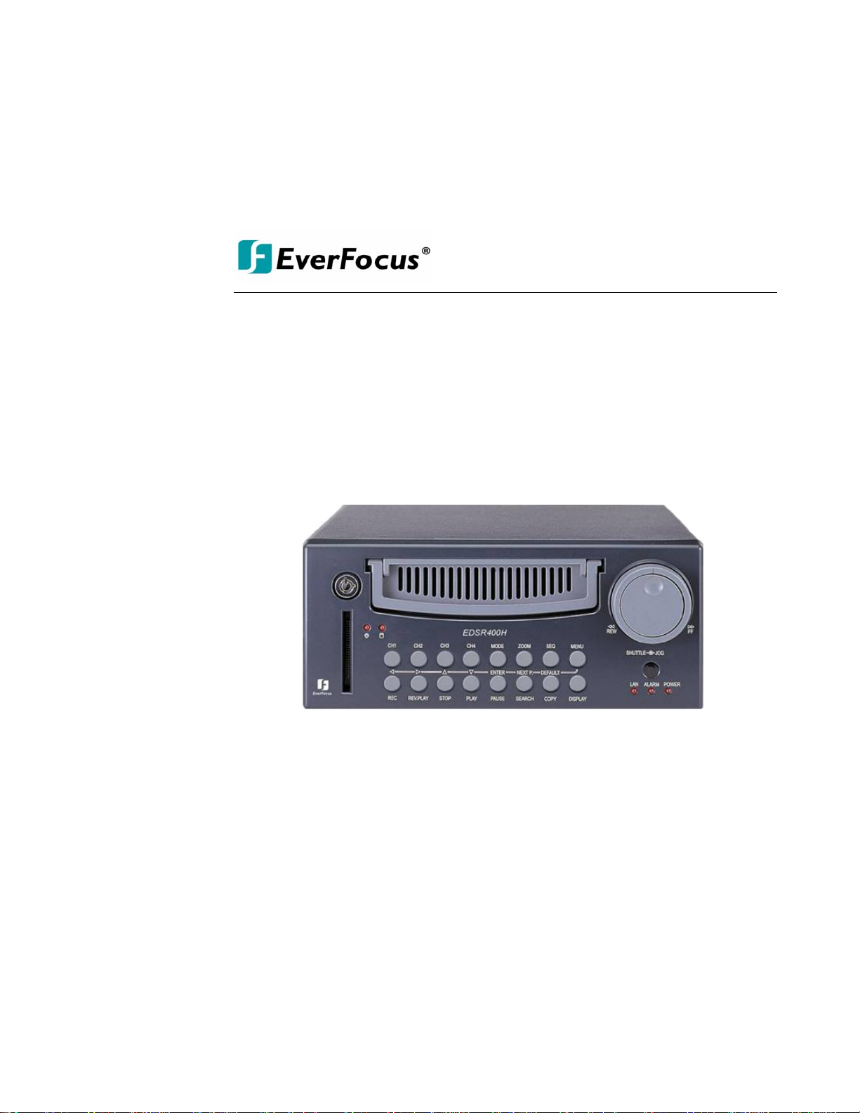
Product Overview
DVRs are the industry’s first full-featured digital video recorder designed specifically
for use within the security industry. The Digital Video Recorder incorporates all the
benefits of digital video recording, is simple to install, and operates just like a VCR.
Highly efficient compression technology and superior resolution of recorded images
make the Digital Video Recorder stand out from the competition as the best choice for
security surveillance.
Fea tures
¾ Easy-to-use control panel with common VCR and Multiplexer functions.
¾ Shuttle/Jog dial for picture-by-picture or fast/slow viewing.
¾ No tapes to manage, clean, or replace.
¾ Instant retrieval of stored video.
¾ On-screen setup menu and system timer.
¾ Ethernet TCP/IP connectivity for remote viewing.
¾ Pre-Alarm and Post-Alarm process.
¾ Built-in M-JPEG compression/decompression with configurable quality.
¾ Programmed with various time-lapse speeds.
¾ 3.5” IDE Type Hard Disks for storage with Hot-Swap tray.
¾ RS232 and RS485 for Remote Control.
¾ Real-Time Live Display for all Cameras.
¾ Variable recording speeds up to 60/50 fps for NTSC/PAL.
¾ Alarm-activated recording.
¾ Data can be stored in a Compact Flash Card.
¾ Audio recording capabilities.
1
Page 6

EVERFOCUS ELECTRONICS CORPORATION
Specifications
Video Format NTSC/PAL
Video Input 4 camera inputs (BNC),1Vp-p/75ohm
Video Output 1 BNC video out (1Vp-p/75 ohm) for Main Monitor
1 BNC video out (1Vp-p/75 ohm) for CALL Monitor
4 video out (1Vp-p/75ohm)for looping
Video Compression M-JPEG
Recording Resolution 720x484 (NTSC); 720x576 (PAL)
Compact Flash Memory Yes, Built-in Compact Flash card slot
Alarm Input 4 alarm inputs
Alarm Output 1 alarm outputs
Video Display Full, PIP, Quad and 2x2 zoom for Live and Playback
Video Loss Detection Yes
Ethernet RJ45 connectors for network communications
Event Log Yes
Hard Disk Storage 3.5” IDE type, Hot- swappable
Recording Mode Continuous, Time-lapse recording, Schedule or Event
Recording
Recording Rate Up to 60/50 fps for NTSC/PAL
Playback Rate Up to 60/50 fps for NTSC/PAL
Playback Search By Date/Time or Event/Segment
Setup On screen display setup
User Interface Menu Driven
User Input Device Front Panel Keypad
Timer Built-in real time clock
Watch Dog Timer Yes
RS-232 9-pin female connector
RS485 RJ11 Connector
Dimension 320.8mm (L) x 215mm (W) x 100mm (H)
Operating Temperature 0C~+40C
60 W Power Consumption
Power Source AC100~240V
Page 7
EVERFOCUS ELECTRONICS CORPORATION
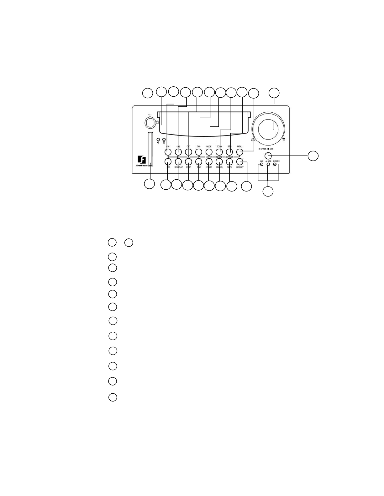
Front Panel K eypads
1
17
18
2
43 7
5 6
8
19
22
20
10
9
11
12
13
14
16
15
21
Keys:
1
~
4
5
6
CH1 ~CH4:
MODE:
Press to switch between Picture-In-Picture and Quad modes.
ZOOM: Pressing this key while viewing a full screen image will display a magnified resolution
of the image on the monitor.
7
SEQ:
Press this key to enter the auto sequential switching mode.
8
MENU: Press this key to enter Setup menu.
9
REC : Press this key to start recording.
10
REV. PLAY : Pressing this key will start reverse playback.
11
STOP : Press this key to stop recording and playback.
12
PLAY: Press this key to playback.
13
PAUSE: Press this key to pause the playback picture.
Press channel key (1~4) to display the video image in full screen
format for the channel specified.
14
SEARCH: Press this key to enter the Search Menu.
15
COPY: Under PAUSE or PLAYBACK, Press this key to start copy still picture or video
stream onto a Compact Flash card.
Page 8
EVERFOCUS ELECTRONICS CORPORATION
l
16
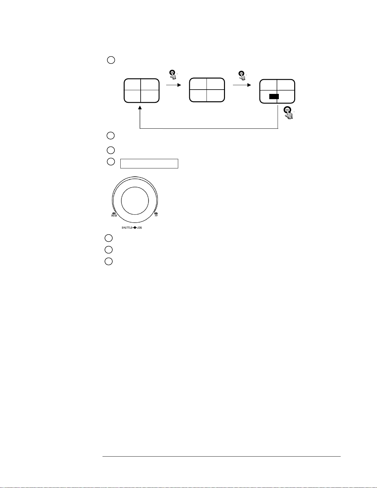
Display: Pressing this key once will turn the display on. Pressing it a second time will give you
Hard Disk Drive statistics.
CH1 CH2
2003/04/22
10:41:00
Disk:120 GB(0)
CH3 CH4
Display OFF
17
HDD KEY: Turning this key to the lock position will activate the Hard Drive for recording
Display Date/Time and Titles
CH1 CH2
2003/04/22
10:42:00
LIVE: 60IPS
DISK:80G
CH3 CH4
and keep it securely locked into the DVR.
18
Hard Disk Tray: Hard Disk holder for HDD.
19
Shuttle and Jog Dia
Shuttle : In Playback mode, turn the shuttle dial can fast
forward/rewind the picture.
In Pause mode, turn the shuttle dial can slow forward/rewind
the picture.
Jog Dial :
In Pause mode, turn the jog dial can forward/rewind the
Picture.
In Menu mode turn the jog dial to change setting Menu
page.
20
Compact Flash Card Slot: Insert a Compact Flash Card.
21
LEDs: LEDs for system active power ,LAN and ALARM access.
22
Remote Control: IR Remote receiver
Page 9
EVERFOCUS ELECTRONICS CORPORATION
W
W
W
A
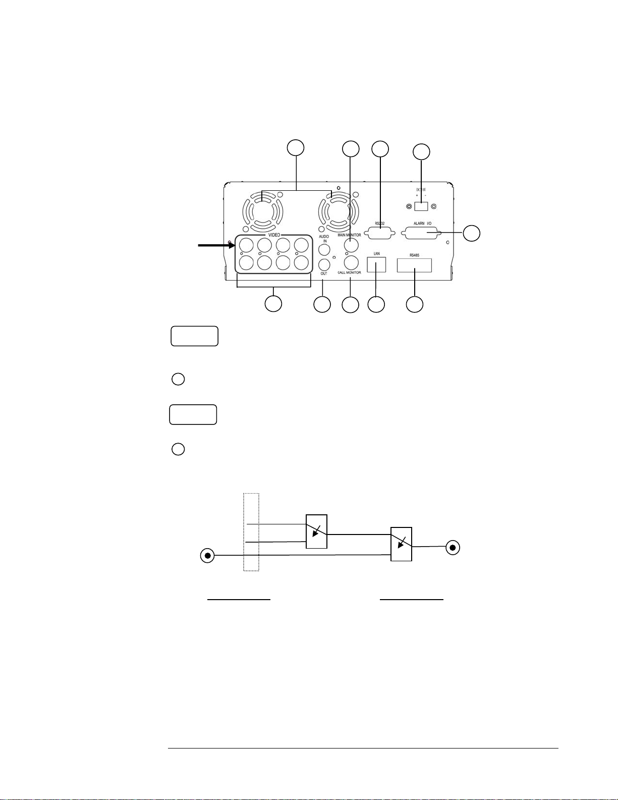
Back Panel Connections
Video In
POWER
1
AUDIO
10
5
3
8
2
4
7 9
1
6
Main Power plug: Connect the DC12~24V power source to Adapter for AC100~240V.
2
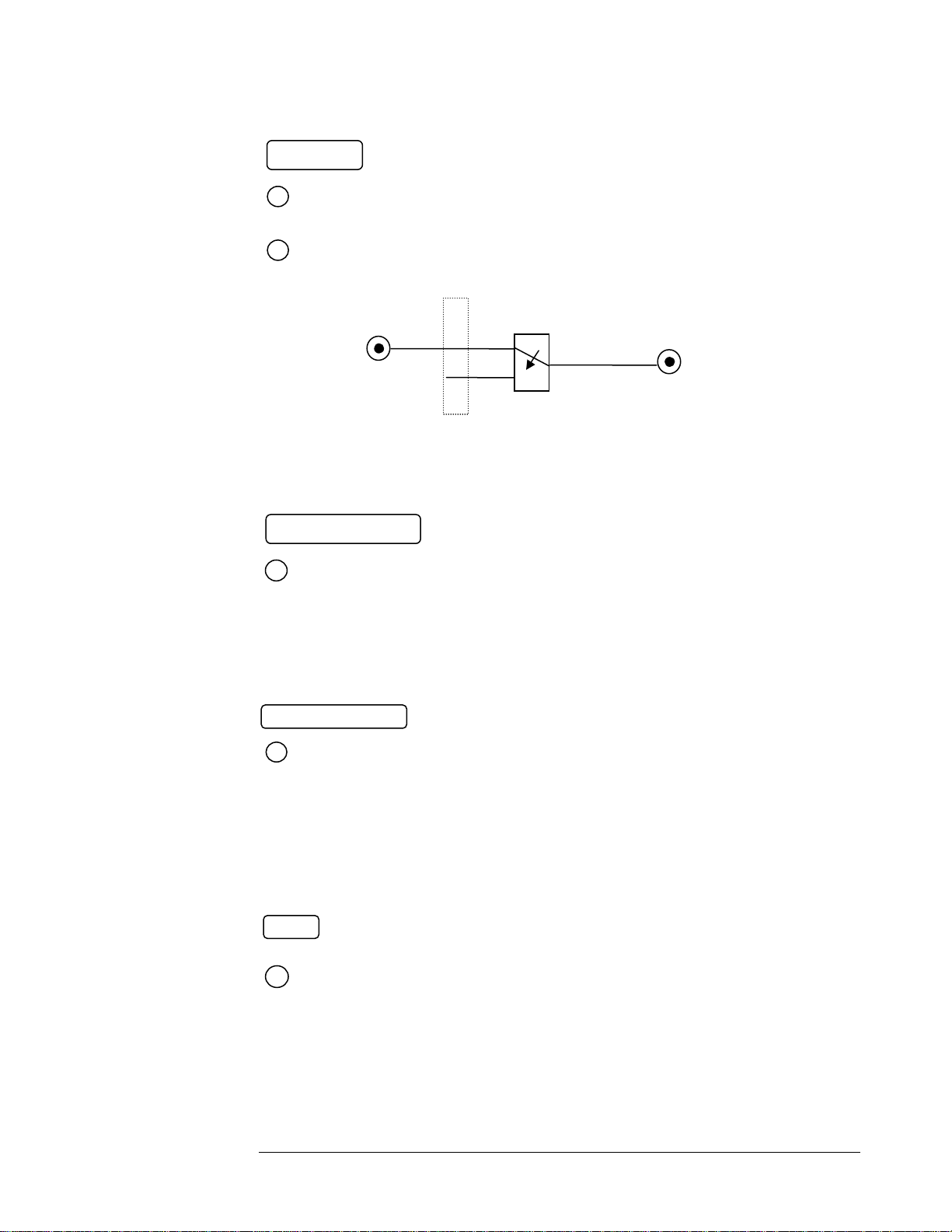
Audio IN: Audio input for recording.
Audio OUT: Audio output can be set to “ON” or “OFF” in Setup Menu.
( Internal circuit )
SW1
Audio OUT
Operation of SW2:
When Playback Audio is enabled then the output of SW2
will be connected to Playback Audio.
hen Playback Audio is disabled then there is no
audio output (MUTE).
Audio IN
SW1 is connected to Audio IN.
connected to SW2 Audio.
SW2
OFF / Mute
Playback Audio
Operation of SW1:
hen in recording or standby mode, the out of
hen in playback mode the out of SW1 is
When Audio Out is enabled and machine is in Recording or Standby mode, the Audio IN is loopthrough to Audio Out connector. When Audio Out is enabled and machine is in Playback mode then the
Audio Out playback audio.
Page 10
EVERFOCUS ELECTRONICS CORPORATION
T
A
W
T
A
MONITOR
3
MAIN MONITOR: This connector is used for the Main monitor display, a number of
different display modes may be selected for viewing. This output
must be used to display the menu settings.
4
CALL MONITOR:
his connector is used for the Call (secondary) monitor.
This monitor can only display full screen pictures.
MAIN
MONITOR
hen the machine is in Menu, Search or Copy mode, the internal Video is switched to Monitor Out, so that the user can view
full screen OSD. In other modes, the Video from multiplexer main monitor will be loop-through to the Monitor Out.
INTERNAL
VIDEO
( Internal circuit )
SW3
MONITOR OUT
VIDEO In/Output
VIDEO IN (1~4):
5
he BNC connectors of video input enable the system to receive the
signals from each camera through the 75 ohm coaxial cables.
VIDEO OUT (1~4): Sends the signals from each camera to other external devices
(loop out).
Alarm Input/ Output
6
larm Input
ALARM-INPUT: Normal Open or Normal Close type alarm sensor input. The Alarm Input
can be selected as Normal Open or Normal Close input in the setup menu.
When an alarm occurs, alarm recording will automatically start.
ALARM-OUTPUT: Normal Close Alarm output. In normal condition, this terminal is
shorted to the terminal of ALARM-COM. In alarm status, it is
open between ALARM-NC and ALARM-COM terminals.
LAN
7
LAN Connector:The RJ-45 LAN connector used to connect to a local area
network.
Page 11

EVERFOCUS ELECTRONICS CORPORATION
RS232
8
RS232 connector: Connect D-Sub 9 pin connector to RS232 port for remote
control.
RS485
9
RS485 connector: RJ 45 Connector to Cascade multi Digital Video Recorder.
10
FAN: Cooling FAN.
Page 12
EVERFOCUS ELECTRONICS CORPORATION
Chapter
2
Installation
The installations described below should be made by qualified service personnel or system installers.
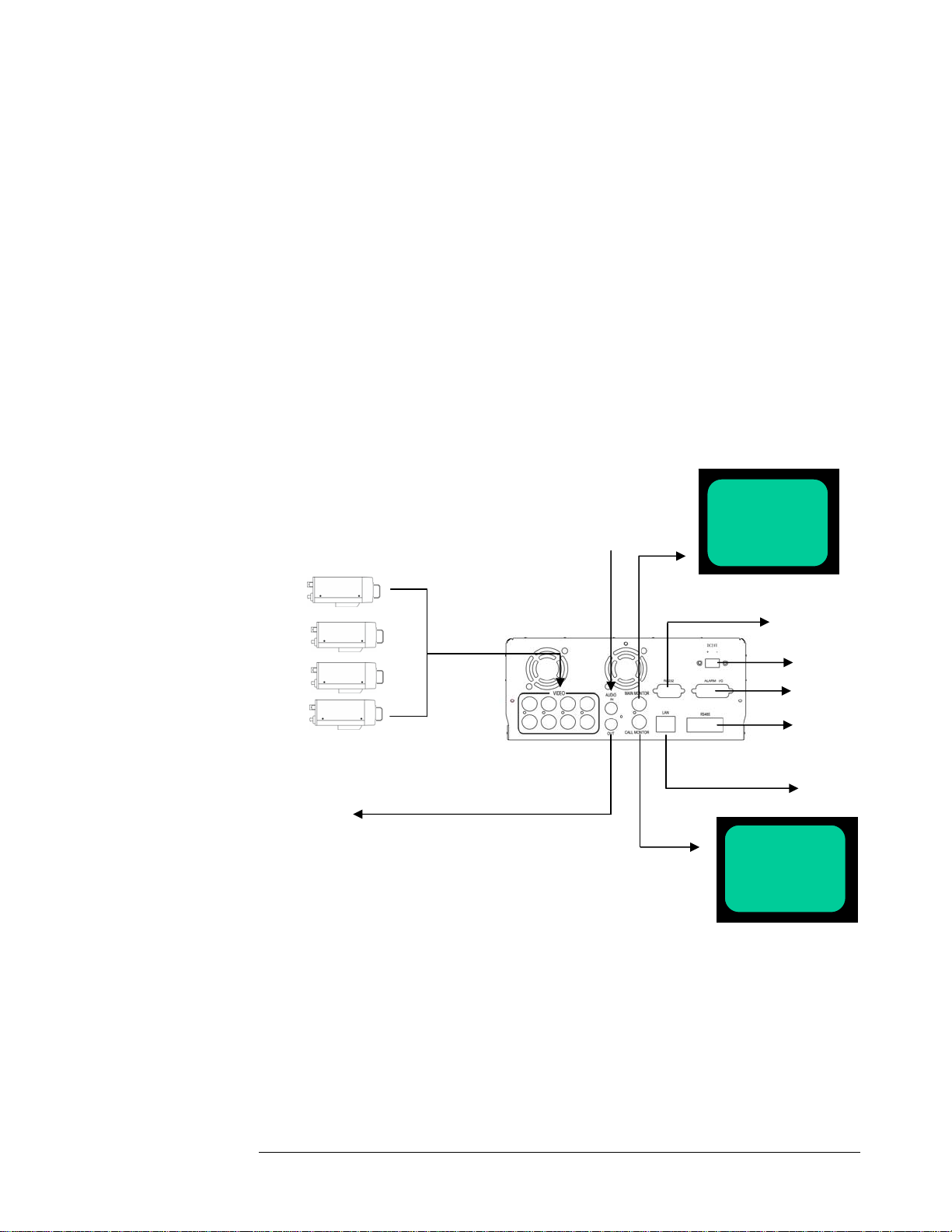
Please refer to the following diagram for the basic wiring connections.
¾ Please note: Monitors and Cameras must be purchased separately.
Speaker
Audio Input
Main Monitor
RS232
Camera 1~4
Power Source
Alarm In/Out
RS485
Ethernet
CALL Monitor
Diagram 1
Page 13

EVERFOCUS ELECTRONICS CORPORATION
Basic Wiring Instructions
Please refer to diagram 1 on page 9 to assist you with this portion of the ins
nect the power source or adapter into the power sock
tallation.
et shown in ¾ Power: Con
diagram 1.
Please note: Do not plug the digital video recorder into the sa
ower source as the cameras.
p
¾ Cameras: Connect each cameras video output to the video input (Top row
connections) on the digital video recorder shown in diagram 1.
Please note: At least one camera must be connected before
the system
is running for the auto detection of video standard to take effect.
¾ Audio Input: Connect the according audio device refereed on chapter 7.
¾ Speaker: Connect the according audio device refereed on chapter 7.
¾ Ethernet: The digital video recorder may be viewed from a PC via the LAN
connector using a RJ45 Ethernet cable.
¾ RS232/RS485: The digital video recorder may be controlled from a PC via
RS232/RS485.
me
Please note: This can be done using a serial cable.
¾ Main Monitor: Connect the main monitor output connector to a main
monitor. The main monitor displays selected live or recorded cameras in any
available format.
Please note: The main monitor must be connected in order to make
configuration changes, enter the main menu, or do a playback at the
machine.
¾ Call Monitor: Connect the call monitor output connector to a call monitor.
The call monitor displays selected live cameras in full screen format.
Please note: The call monitor will only display one full screen camera
at a time.
Page 14

EVERFOCUS ELECTRONICS CORPORATION
Hard Disk Drive Installation
The first step in installing the hard drive is to insert the hard drive sleeve in
the machine. The hard disk drive default setting is initially set to master or cable select.
The
second step is to insert the key provided and turn the tray key to the lock position.
If this process is ignored the hard disk drive will not be detected.
Final In
Please verify you have th
pro
gram the DVR.
1. Verify all the cameras are connected to the back of the DVR on the (
2. Verify the monitor is connected to the Main Monitor output
3. Hard Drive(s) are in position and locked with the key.
Fina
installation you are read to turn on the DVR. Simply plug the power source you
installed ear . is normal. The next
step is to se
stallation Check List
e following connections before proceeding to the
Input Top
row) C
BN connections.
l Install Process
Once you have completed the basic wiring installation and the hard disk drive
lier The POWER LED lights will light up if power
t up the menu options for the DVR.
to
Page 15

EVERFOCUS ELECTRONICS CORPORATION
Chapter
3
DVR Menu Setup
Assuming you have completed the first two chapters of this manual. You are
now ready to begin setting up the digital video recorder menu. To begin this process
press the MENU key. Once inside the main menu you will find there are 13 setup
ion
opt pages as follows.
1. CLOCK/LANGUAGE SETTING MENU
2. TITLE SETTING MENU
3. DAYLIGHT SAVING SETTING MENU
4. TIMER SETTING MENU
5. NORMAL RECO
6. ALARM RECORD SETTING MENU
7. BUZZER SETTING MENU
8. ARCHIVE SETTING MENU
9. NETWORK SETTING MENU
10. SEQUENCE SETTING MENU
11. RS232/RS485 SETTING
12. MOTION RECORD SETTING MENU
RD SETTING MENU
13. SYSTEM SETTING MENU
Turning the jog dial clockwise or counter clockwise will allow you to
scroll through the different menu setup option pages.
Page 16
EVERFOCUS ELECTRONICS CORPORATION
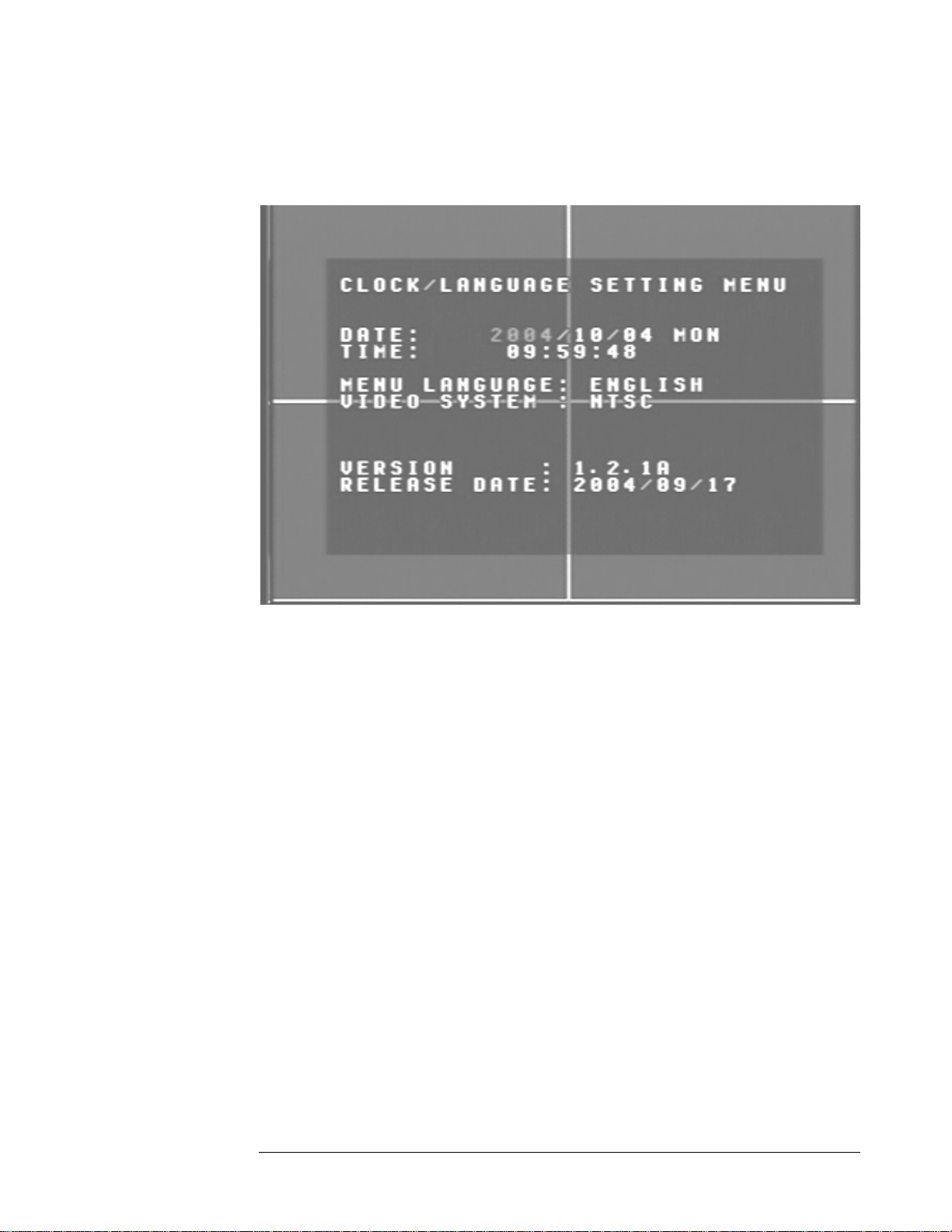
Clock/Language Setting Menu
Diagram 2
Diagram two is a screen shot of the Clock/Language Setting Menu. In the
Clock/Lang are defined as follows:
uage Setting Menu the following fields
¾ date on the DVR. To change this,
Date: This field represents the current
simply use the arrow keys on the DVR which also represent the CH1,
CH2, CH3 and CH4 keys (These are the
top four left buttons). Use the up
and down arrow keys to make your selection.
The date is represented as follows:
Year: 2000~2099 / Month: 01~12 / Date: 01~
¾ t time on the DVR which is in
Time: This field represents the curren
military time. To change this, simply
use the arrow keys on the DVR
31 (Day of Week)
which also represent the CH1, CH2, CH3 and CH4 keys (These are the
to
p four left buttons). Use the up and down arrow keys to make your
se
lection.
The date
is represented as follows:
Hour: 00~23 : Minute: 00~59 : Second: 00~59
Page 17

EVERFOCUS ELECTRONICS CORPORATION
¾ Menu Language: This field is set to English from factory and can not be
changed.
¾ Video System: This field is set to NTSC from factory which is the North
American Video Standard and can not be changed. The European and
Asian Video Standards are PAL.
¾ Version: This field represents the firmware version the digital video
recorder is using.
Please note: New firmware versions are available for download from
our ftp site. ftp://208.50.31.200/
(see page for firmware upgrade
instructions)
¾ Release Date: This field represents the date the firmware was released.
: Press or to move the cursor to the left or right.
: Press or to change the value.
These keys are
as channel 1-4).
located at the top left row of keys (same keys
Page 18
EVERFOCUS ELECTRONICS CORPORATION
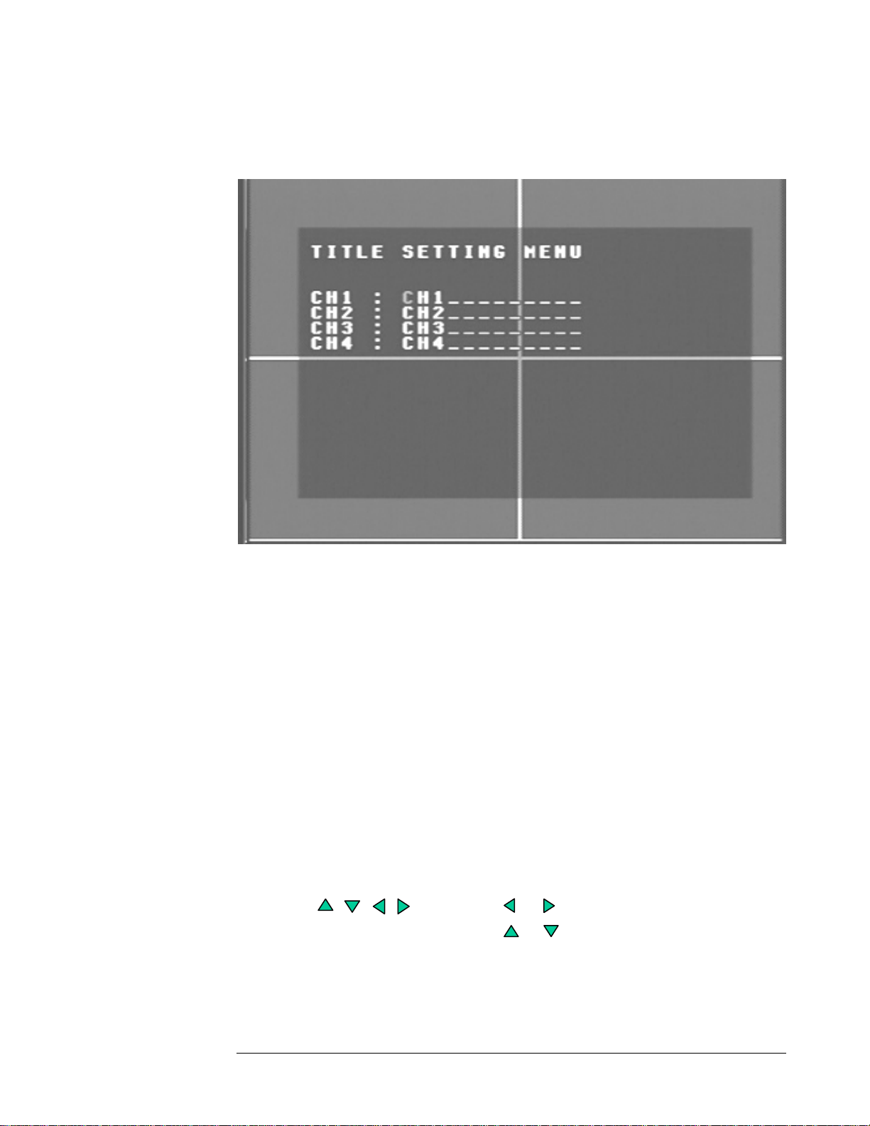
Title Setting Menu
Diagram 3
Diagram three is a screen shot of the Title Setting Menu. In this menu you can set a
unique title for each of your cameras. To change this, simply use the arrow keys on the
DVR which also represent the CH1, CH2, CH3 and CH4 keys (These are the top four
left buttons). Use the up and down arrow keys to make your selection.
Example:
¾
CH1 : FrontDoor
CH2 : BackDoor
CH3 : Hallway
CH4 : Closet
: Press or to move the cursor to the left or right.
: Press or to change the value.
These keys are located at the top
as channel 1-4).
left row of keys (same keys
Page 19
EVERFOCUS ELECTRONICS CORPORATION
Daylight Setting Menu
Diagram 4
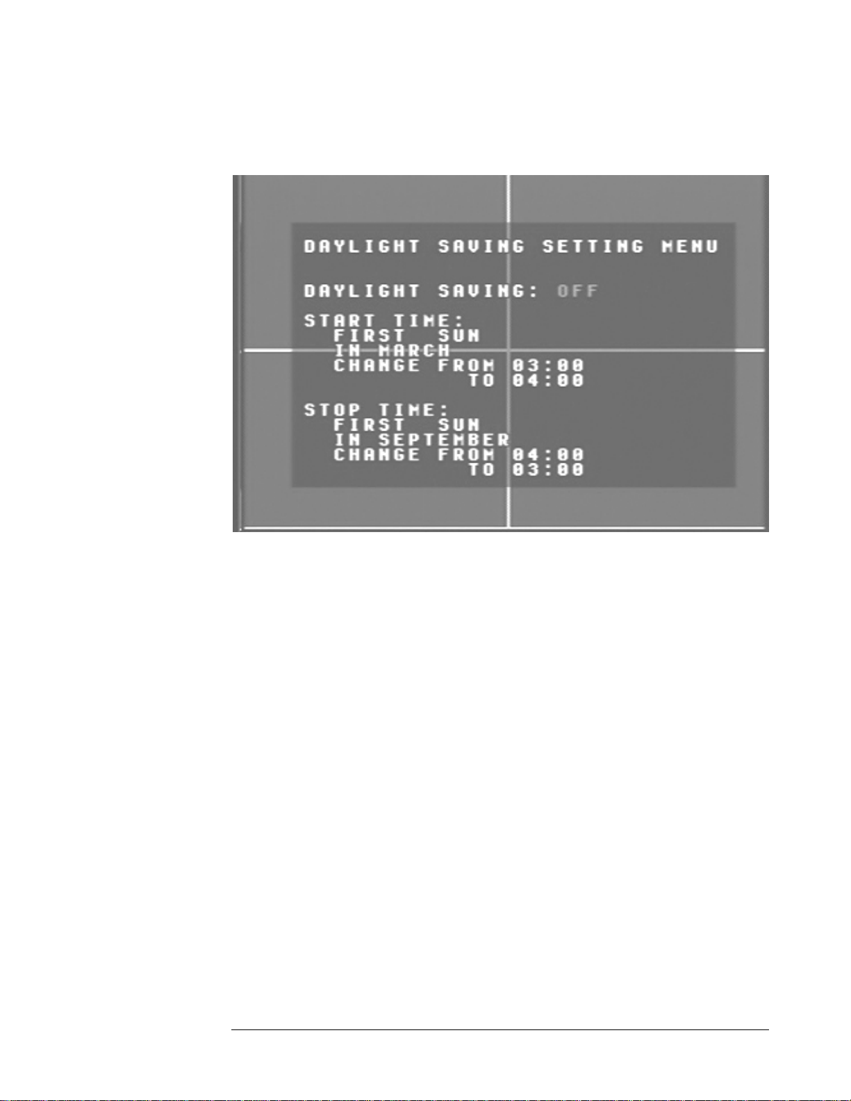
Diagram four is a screen shot of the Daylight Saving Setting Menu. In this menu you
can set the DVR to adjust the daylight savings time automatically for you.
¾ Daylight saving: This field is to turn the daylight savings
function on or
off. To change this, simply use the arrow keys on the DVR which also
represent t
but up
tons). Use the and down arrow keys to make your selection.
he CH1, CH2, CH3 and CH4 keys (These are the top four left
¾ Start Time: This field signifies the date the daylight savings will take affect.
he first field is set to “First”. This signifies the week of the month the
T
aylight savings time will change. Your options are: first, second, third,
d
urth, or last. Use the up and down arrow keys to make your
fo
lection.
se
he next field is set to “Sun”. This represents the day of the week the
T
daylight savings time will take aff
Wed, Thurs, Fri, or
Sat. Use the up and down arrow keys to make
ect. Your options are: Sun, Mon, Tue,
your selection.
Page 20

EVERFOCUS ELECTRONICS CORPORATION
The third field is set to
daylight savings time w
“March”. This signifies the month in which the
ill occur. Your options are: Jan through Dec.
Use the up and down arrow keys to make your selection.
The last two fields represent the time. Use the up and down arrow
keys to choose the time you want to go from to the time you want it to
be.
¾ Stop Time: This field represents when the daylight savings time will come
to an end. Use the same steps you used for the Start Time to make the
necessary changes for the Stop Time.
: Press or to move the cursor to the left or right.
: Press or to change the value.
These keys are located at the top left row of keys (same keys
as channel 1-4).
Page 21
EVERFOCUS ELECTRONICS CORPORATION
Timer S t e ting Menu
Diagram 5
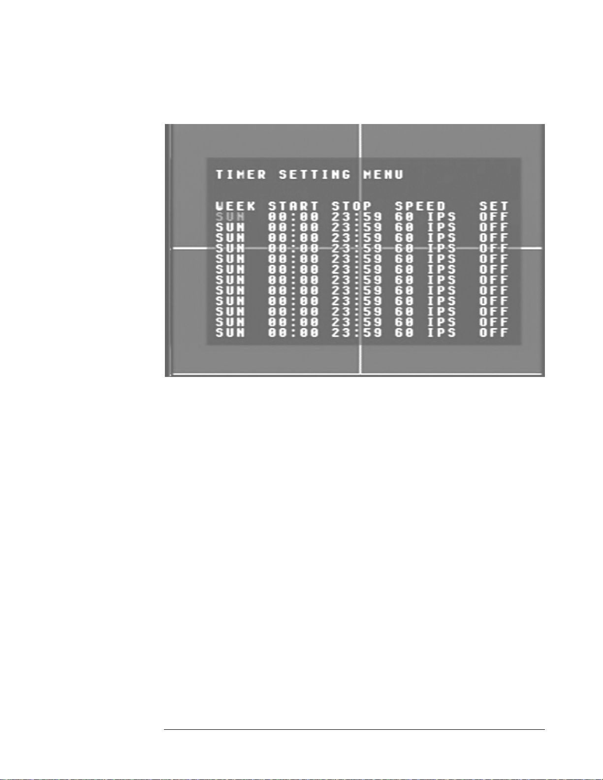
iagram five is a screen shot of the Timer Setting Menu. In this menu you can set a
D
nique timer any day of the week to start recording from a specified start time to an
u
end time. In the Timer Setting Menu
the following fields are defined as:
¾ Week: This field represents the day of the week you wish to set the timer
record for. Initially it is set to Sun as default. You may choose from MonSun as well as DLY. If you wish to create a daily timer for every day of the
week you may choose the DLY option. To change this, simply use the
arrow keys on the DVR which also represent the CH1, CH2, CH3 and
CH4 keys (These are the top four left buttons). Use the up and down
arrow keys to make your selection.
¾ Start: This field is used to set the time you wish to start the timer recording.
To change this, simply use the arrow keys on the DVR which also
represent the CH1, CH2, CH3 and CH4 keys (These are the top four left
buttons). Use the up an
d down arrow keys to make your selection.
¾ Stop: This field is used to set th
recording. To change t
also represent the CH1 These are the top four
his, simply use the arrow keys on the DVR which
, CH2, CH3 and CH4 keys (
e time you wish to stop the timer
left buttons). Use the up and down arrow keys to make your selection.
Page 22

EVERFOCUS ELECTRONICS CORPORATION
¾ Speed: This field is used th
record to be recording ha
to set e speed at which you would like the timer
at. To c nge this, simply use the arrow keys on the
DVR which also represent the CH1, CH2, CH3 and CH4 keys (These are
the top four left buttons). Use the up and down arrow keys to make your
selection.
Please Note: See Appendix B to find the appropriate speed to fit your
recording needs.
¾ Quality: This field is for setting up video recording quality, this item lets
you set the quality of the video picture by selecting a compression rate.
There are six quality levels for recording:
Lower : 15KB
Low : 19KB
Basic : 23KB
Standard : 27KB
High : 31KB
Superior : 35KB
To change this, simply ow keys on the DVR which also
use the arr
represent the CH1, CH2, CH3 and CH4 keys (These are the top four left
buttons). Use the up and down arrow keys to make your selection.
¾ Set: This field is used to turn the timer recording on or off. To change th
simply use the arrow keys on the DVR which also represent
the CH1,
is,
CH2, CH3 and CH4 keys (These are the top four left buttons). Use the up
and down arrow keys to make your selection.
Please note: If you wish to do any form of playback this feature must
be turned off before attempting to playback.
: Press or to move the cursor to the left or right.
: Press or to change the value.
These keys are located at the top left row of keys (same keys
as channel 1-4).
Page 23
EVERFOCUS ELECTRONICS CORPORATION
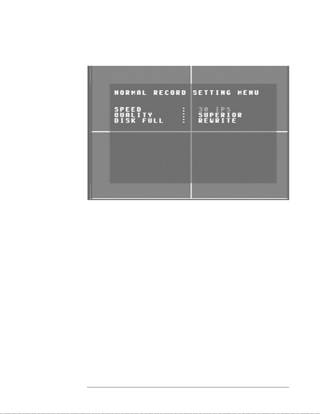
Norm al Record Setting Menu
Diagram 6
iagram six ntains
D
e spee
th d and quality for recording all the time. In the Normal Record Setting Menu
the followin
is a screen shot of the Normal Record Setting Menu. This menu co
g fields are defined as:
¾
Speed: This field represents the speed at which the recorder will be
recording all the time. To change this, simply u
se the arrow keys on the
DVR which also represent the CH1, CH2, CH3 and CH4 keys (These are
the top four left buttons). Use the up and down arrow keys to make your
sele
ction.
Please Note: See Appendix B to find the appropriate speed to fit your
recording needs.
¾ Quality: This field is for setting up video recording quality, this item lets
you set the quality of the video picture by selecting a compression rate.
There are six quality lev
Lower :
Low :
Basic :
els for recording:
15KB
19KB
23KB
Page 24

EVERFOCUS ELECTRONICS CORPORATION
Standard : 27KB
High : 31KB
Superior : 35KB
To change this, simply use the arrow keys on the DVR which also
represent the CH1, CH2, CH3 and CH4 keys (These are the top four left
buttons). Use the up and down arrow keys to make your selection.
¾ Disk Full: This field represents what to do when the Hard Disk Drive gets
full. In this case the default is set to Rewrite. The other option if you wish
to do so is to set the disk full option to Stop. This will stop all recording
once the drive has been filled up. You would then have to go to System
Setting Menu and do a Disk Renew in order to format the drive and start
recording again. To change this, simply use the arrow keys on the DVR
which also represent the CH1, CH2, CH3 and CH4 keys (These are the
top four left buttons). Use the up and down arrow keys to make your
selection.
: Press or t o move the cursor to the left or right.
: Pres to change the value.
s or
keys are located at the to
These p left row of keys (same keys
as channel 1-4).
Page 25
EVERFOCUS ELECTRONICS CORPORATION
Alarm R ecord Setting Menu
Diagram 7
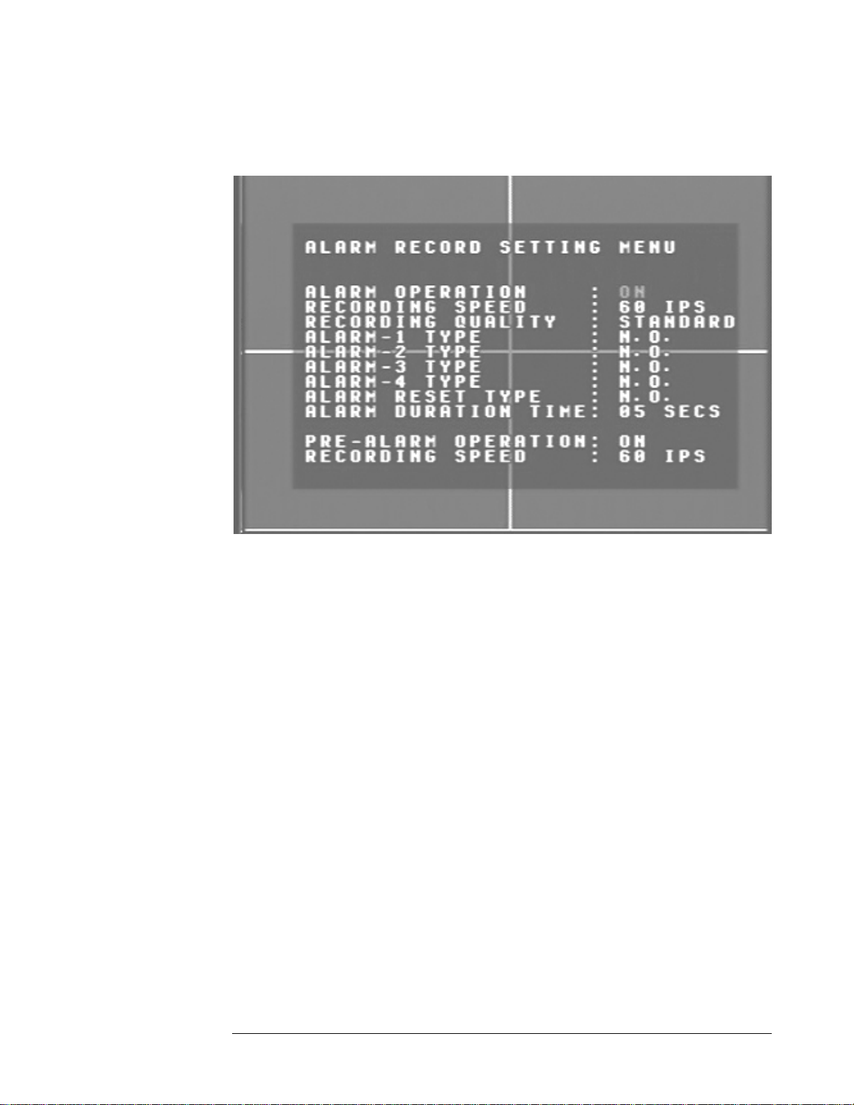
iagram seven is a screen shot of the Alarm Record Setting Menu. This menu contains
D
ll the alarm operations and options needed to successfully complete an alarm
a
cording. In the Alarm Record Setting Menu the following fields are defined as:
re
¾ Alarm Operations: This field is to turn alarm recording on or off. The
Default from the factory is set to on. To change this, simply use the arrow
keys on the DVR which also represent the CH1, CH2, CH3 and CH4 keys
(These are the top four left buttons). Use the up and down arrow keys to
make your selection.
¾ Recording Speed: This field represents the speed at which the recorder will
be recording the alarm event. To change this, simply use the arrow keys on
the DVR which also represent the CH1, CH2, CH3 and CH4 keys (These
are the top four left buttons). Use the up and down arrow keys to make
your selection.
Please Note: See A
ppendix B to find the appropriate speed to fit your
recording needs.
Page 26

EVERFOCUS ELECTRONICS CORPORATION
¾ Recording Quality: This field is for s
item lets you set the quality of the
etting up video recording quality, this
video picture for the alarm event by
selecting a compression rate.
There are six quality levels for recording:
Lower : 15KB
Low : 19KB
Basic : 23KB
Standard : 27KB
High : 31KB
Superior : 35KB
To change this, simply use the arrow keys on the DVR which also
represent the CH1, CH2, CH3 and CH4 keys (These are the top four left
buttons). Use the up and down arrow keys to make your selection.
¾ Alarm 1-4 Types: These fields represent what to do when a signal is
received from the alarm board connector. There are two types of alarm
signals. The first is N.O. which stands for Normally Open circuit. The
Second is N.C. which stands for Normally Closed circuit. The default
setting is N.O. This option would be
input connected to the ala or example if you connected a door
rm board. F
set according to the type of alarm
sensor which was a Normally Open circuit you would set the alarm type to
N.O. To change this, simply use the arrow keys on the DVR which also
represent the CH1, CH2, CH3 and CH4 keys (These are the top fou
r left
buttons). Use the up and down arrow keys to make your selection.
Please note: Refer to Appendix D for more information about setting
up the alarm board.
¾
Alarm Reset Type: This field is to set the alarm signal back to normal. If
you have a N.O. alarm
in the alarm types you would set it back to N.O. If
you have a N.C. circuit you would set it back to N.C. To change this,
simply use the arrow keys on the DVR which also represent the CH1,
CH2, CH3 and CH4 keys (These are the top four left buttons). Use the up
and down arrow keys to make your selection.
¾ Time: When any sensor alarm connected to the device is
Alarm Duration
activated, the device will immediately react an alarm and display the
warning message. This entry is used to set the alarm duration from 1 to 99
seconds. To change this, simply use the arrow keys on the DVR which
lso represent the CH1, CH2, CH3 and CH4 keys (These are the top four
a
left buttons). Use the up and down arrow keys to make your selection.
Page 27

EVERFOCUS ELECTRONICS CORPORATION
Pre-Alarm Operation: This feature turns the pre-alarm recording on or off.
To change this, simply use the arr¾ ow keys on the DVR which also
represent the CH1, CH2, CH3 and CH4 keys (These are the top four left
buttons). Use the up and down arrow key
s to make your selection.
¾ S eed: This optio et the speed of the pre-alarm
Recording p n is to s
recording. To change this, simply use the arro
also represent the CH1, CH2, CH3 and CH
left buttons). Use the up and down arr
ow keys to make your selection.
w keys on the DVR which
4 keys (These are the top four
: Press or to move the cursor to the left or
: Press or to change the value.
These keys are located at the top left row of keys (same keys
as channel 1-4).
right.
Page 28
EVERFOCUS ELECTRONICS CORPORATION
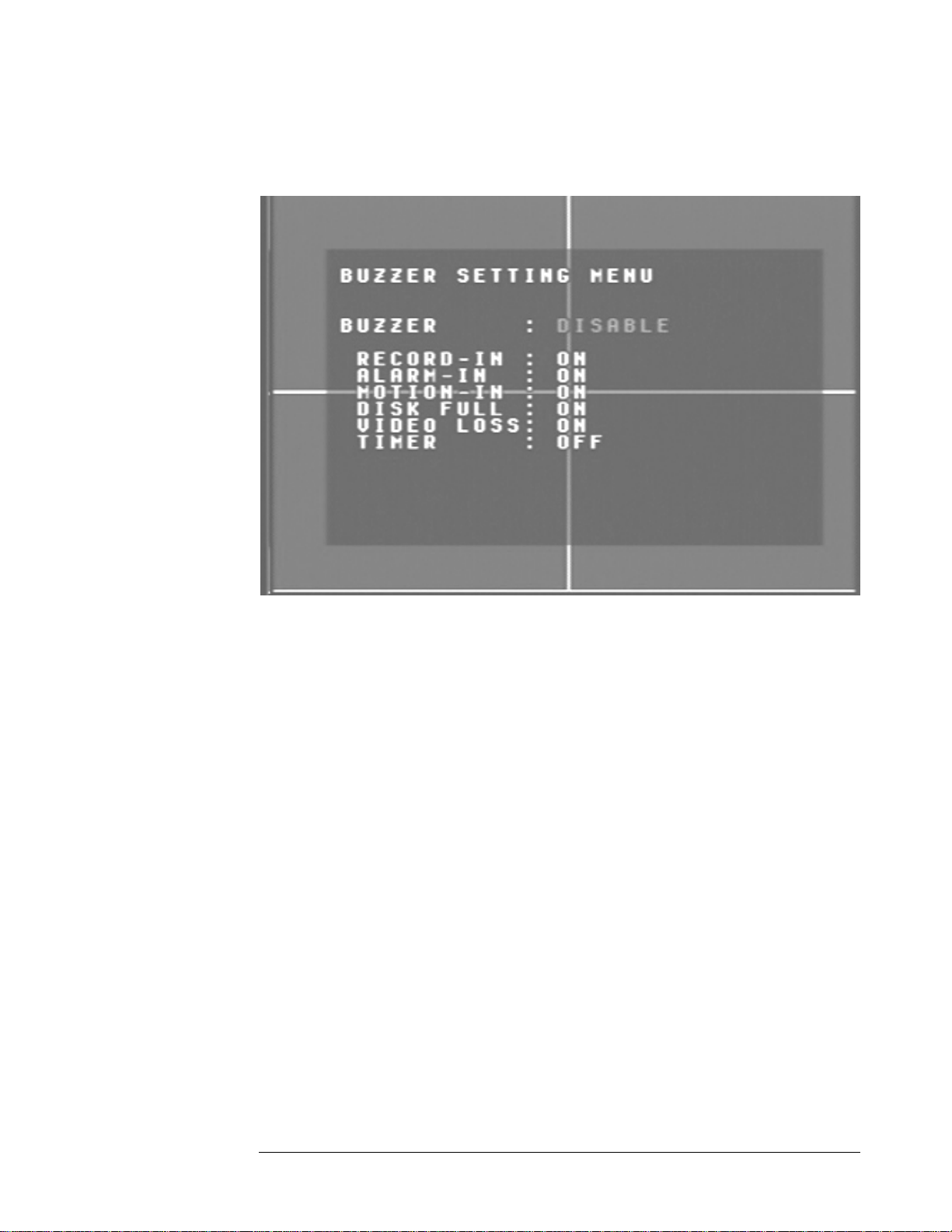
Buzz er Setting Menu
Diagram 8
iagram eight is a screen shot of the Buzzer Setting Menu. This menu is to set the
D
ternal buzzer. In the Buzzer Setting Menu the following fields are defined as:
in
¾ Buzzer: This field is to turn the internal buzzer enable or disable the
internal buzzer. The default is set to enable. To change this, simply use the
arrow keys on the DVR which also represent the CH1, CH2, CH3 and
CH4 keys (These are the top four left buttons). Use the up and down
arrow keys to make your selection.
¾ Record-In: This option is to turn the buzzer on or off when the DVR is in
record mode. To change this, simply use the arrow keys on the DVR
which also represent the CH1, CH2, CH3 and CH4 keys (These are the
top four left buttons). Use the up and down arrow keys to make your
selection.
¾ Alarm-In: This field is to turn the
is enabled. To change this, simply
also represent the CH1 re the top four
, CH2, CH3 and CH4 keys (These a
buzzer on or off when alarm recording
use the arrow keys on the DVR which
left buttons). Use the up and down arrow keys to make your selection.
Page 29

EVERFOCUS ELECTRONICS CORPORATION
¾ Motion-In: This option i
recording is enabled. To ch
s to turn the buzzer on or off when motion
ange this, simply use the arrow keys on the
DVR which also represent the CH1, CH2, CH3 and CH4 keys (These are
the top four left buttons). Use the up and down arrow keys to make your
selection.
¾ Disk Full: This field is to turn the buzzer on or off when the Hard Disk
Drive is full. To change this, simply use the arrow keys on the DVR which
also represent the CH1, CH2, CH3 and CH4 keys (These are the top four
left buttons). Use the up and down arrow keys to make your selection.
¾ Video Loss: This option is to turn the buzzer on or off when the DVR
experiences video loss. To change this, simply use the arrow keys on the
DVR which also represent the CH1, CH2, CH3 and CH4 keys (These are
the top four left buttons). Use the up and down arrow keys to make your
selection.
¾ Timer: This field is to turn the buzzer on or off when timer recording is
activated. To change this, simply use the arrow keys on the DVR which
also represent the CH1, CH2, CH3 and CH4 keys (These are the top four
left buttons). Use the up and down arrow keys to make your selection.
: Press or to move the cursor to the left or right.
: Press or to change the value.
These keys are located at the top left row of keys (same keys
as channel 1-4).
Page 30
EVERFOCUS ELECTRONICS CORPORATION
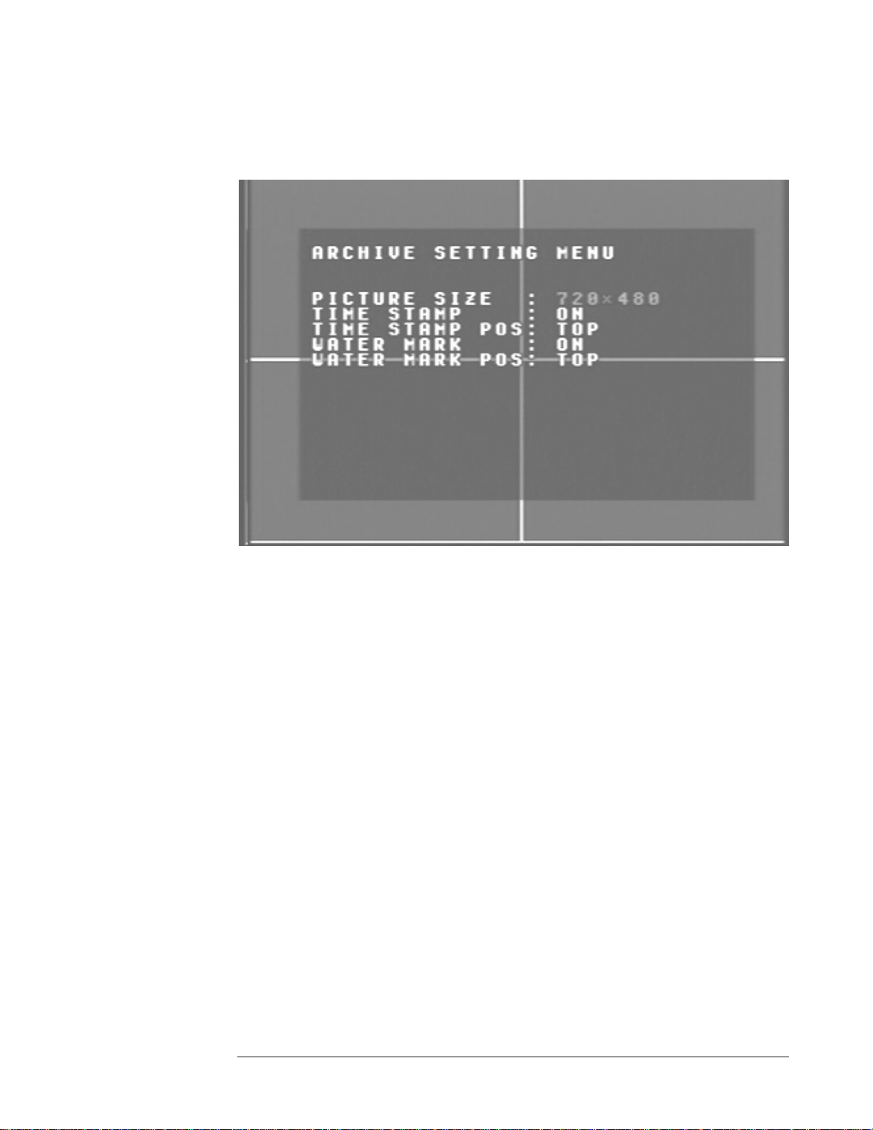
Arch ive Setting Menu
Diagram 9
iagram nine is a screen shot of the Archive Setting Menu. This menu is for setting up
D
e way in which video is archived within the machine. In the Archive Setting Menu
th
e following fields are defined as follows:
th
¾ Picture Size: This field is to set the picture size for copying an image to a
Compact Flash card or through the network. Initial default is set to the
larger size 720 x 480 for NTSC or 720 x 576 for PAL. The smaller size is
352 x 240 for NTSC or 352 x 288 for PAL.
Please Note: To speed up refresh rate through the network set picture
size to 352 x 240 for NTSC or 352 x 288 for PAL.
To change this, simply use the arrow keys on the DVR which also
represent the CH1, CH2, CH3 and CH4 keys (These are the top four left
buttons). Use the up and down arrow keys to make your selection.
¾ Time Stamp: This opti
DVR is in record mod archiving
on is to turn the time stamp on or off when the
e. The time stamp will appear when
through the network or to a Compact Flash card. To change this, simply
use the arrow keys on t
he DVR which also represent the CH1, CH2, CH3
Page 31

EVERFOCUS ELECTRONICS CORPORATION
and CH4 keys (These are
arrow keys to make your s
the top four left buttons). Use the up and down
election.
¾ Time Stamp Position: This field is to set the position of the time stamp.
You can set the time position either on top or bottom. The default is set to
top. To change this, simply use the arrow keys on the DVR which also
represent the CH1, CH2, CH3 and CH4 keys (These are the top four left
buttons). Use the up and down arrow keys to make your selection.
¾ Water Mark: This option is to turn water mark on or off when copying to
a Compact Flash card. By default this option is turned on. To change this,
simply use the arrow keys on the DVR which also represent the CH1,
CH2, CH3 and CH4 keys (These are the top four left buttons). Use the up
and down arrow keys to make your selection.
¾ Water Mark Pos: This field is set the water mark position. You can set the
water mark to either the top or the bottom. The factory default is set to
top. To change this, simply use the arrow keys on the DVR which also
represent the CH1, CH2, CH3 and CH4 keys (These are the top four left
buttons). Use the up and down arrow keys to make your selection.
: Press or to move the cursor to the left or righ
: Press or to change the value.
These keys are located at the top left row of keys (same keys
as channel 1-4).
t.
Page 32

EVERFOCUS ELECTRONICS CORPORATION
Network Setting Menu
Diagram 10
iagram ten is a screen shot of the Network Setting Menu. This menu is for setting up
D
e configuration for networking to the DVR. Please refer to the Networking Chapter
th
f this manual to fully understand how to setup your network for this DVR. In the
o
etwork Setting Menu the following fields are defined as follows:
N
¾ IP Address: This field is to set a static IP Address for the DVR. A static IP
address is an IP address whose value does not change. EverFocus suggest
using a static IP address. If your Internet provider does not offer a static IP
address you have the option to use a dynamic IP address. For Example: A
Test IP address given to the machine by our engineers is 192.168.010.010.
Please Note: The Addresses in the machine are for our own testing
you must apply your own addresses to comply with your network.
Refer to Networking Chapter for more details.
To change this, simply use the arrow keys on the DVR which also
represent the CH1, CH
buttons). Use the up an lection.
2, CH3 and CH4 keys (These are the top four left
d down arrow keys to make your se
28
Page 33

EVERFOCUS ELECTRONICS CORPORATION
¾ Net mask: This field is to se
DVR will be recognized wit
t the subnet mask for your network so as the
hin the network. Example: 255.255.255.000
To change this, simply use the arrow keys on the DVR which also
represent the CH1, CH2, CH3 and CH4 keys (These are the top four left
buttons). Use the up and down arrow keys to make your selection.
¾ Gateway: This field is to set the gateway for your network so the DVR will
be recognized within the network. An example of this is provided within
the DVR we use to test the machine within our own network. To change
this, simply use the arrow keys on the DVR which also represent the CH1,
CH2, CH3 and CH4 keys (These are the top four left buttons). Use the up
and down arrow keys to make your selection.
¾ Mac Address: This field is for those Internet service providers or Network
administrators who require a MAC address of the network card of our
DVR. This option can not be changed.
¾ User-Name Password Level: This category is to set up the users that
will log into the network. Please remember that this portion of the
Network setting menu is set up in column format.
To change the any of the presets to a more user defined name simple
use the arrow keys on the DVR which also represent the CH1, CH2,
CH3 and CH4 keys (These are the top four left buttons). Use the up
and down arrow keys to make your selection.
Example: USER-NAME Password Level
admin admin
super
Changed to Adam Everfocus super
Please remember there are only three different levels guest, general,
and super.
o “Admin” and “general” – can view live/playback video
o “Guest” – can only view live.
: Press or to move the cursor to the left or right.
: Press or to change the value.
These keys are located at the top left row of keys (same keys
as channel 1-4).
Page 34

EVERFOCUS ELECTRONICS CORPORATION
Sequ ence Setting Menu
Diagram 11
Diagram eleven g
up the way w itor and call monitor
outputs. In S
is a screen shot of the Sequence Setting Menu. This menu is for settin
hich video is sequenced through the main mon
in
the equence Setting Menu the following fields are defined as follows:
¾ Ma is equen
in Monitor: Th field is to s s ce for the m onitoret the ain m
output.
Dwell Time: This field represents the rate at which the cameras will
sequence on
the main monitor. The dwell time for the auto sequence
can be set from 0 to 99 seconds. To change this, simply use the arrow
keys on the DVR which also represent the CH1, CH2, CH3 and CH4
key h s). Use the up and down arrow
s (T ese are the top four left button
keys to make your selection.
Seq with Quad: This field is to turn on or off the quad screen when
the auto sequence mode is on. The default is set to yes. To turn it off
simple change to n
DVR which also re H4 keys (These
o. To change this, simply use the arrow keys on the
present the CH1, CH2, CH3 and C
are the top four left buttons). Use the up and down arrow keys to
make your selectio
n.
Page 35

EVERFOCUS ELECTRONICS CORPORATION
¾ Call Monitor: This field is to se
t the sequence for the call monitor output.
Dwell Time: This field represents the rate at which the cameras will
sequence on the call monitor. The dwell time for the auto sequence
can be set from 0 to 99 seconds. To change this, simply use the arrow
keys on the DVR which also represent the CH1, CH2, CH3 and CH4
keys (These are the top four left buttons). Use the up and down arrow
keys to make your selection.
Operation: This field is to select from camera 1 to 4 for the sequence
screen. The default is set to CH1. To change this, simply use the arrow
keys on the DVR which also represent the CH1, CH2, CH3 and CH4
keys (These are the top four left buttons). Use the up and down arrow
keys to make your selection.
o Please Note: If an alarm occurs call monitor will display that
particular camera automatically.
: Press or to move the cursor to the left or right.
: Press or to change the value.
These keys are located at the top left row of keys (same k
as channel 1-4).
eys
Page 36

EVERFOCUS ELECTRONICS CORPORATION
RS23 2/RS485 Setting Menu
Diagram 12
iagram twelve is a screen shot of the RS232/RS485 Setting Menu. This menu is for
D
tting up a connection from the digital recorder to a computer to transfer instructions
se
r information using the HyperTerminal program in Windows. In the RS232/RS485
o
etting Menu the following fields are defined as follows:
S
S232:
R
¾ RS232 Baud Rate: This field is to set the speed at which is used to transmit
instruction or information through the RS232 port on the DVR. There are
six different speeds, 1200 BPS, 2400 BPS, 4800 BPS, 9600 BPS, 19200
BPS, and 3840 BPS. The default setting from the factory is 9600 BPS. To
change this, simply use the arrow keys on the DVR which also represent
the CH1, CH2, CH3 and CH4 keys (These are the top four left buttons).
Use the up and down arrow keys to make your selection.
¾ RS232 Stop Bit: This fi
There are two different DVR is set to
eld is to set the stop bit for the RS232 connection.
stop bits, 1 or 2. The default in the
1. To change this, simply use the arrow keys on the DVR which also
represent the CH1, CH
buttons). Use the up an your selection.
2, CH3 and CH4 keys (These are the top four left
d down arrow keys to make
Page 37

EVERFOCUS ELECTRONICS CORPORATION
RS485:
¾ RS232 Parity: This field is to select th
connected. You can choose between
e parity level at which you will be
None, Odd, or Even parity levels.
Default is set to None. To change this, simply use the arrow keys on the
DVR which also represent the CH1, CH2, CH3 and CH4 keys (These are
the top four left buttons). Use the up and down arrow keys to make your
selection.
¾ RS232 Data Bit: This field is the data bit at which you will be transferring.
There are two settings for this option: 8 or 7. The default is set to 8. To
change this, simply use the arrow keys on the DVR which also represent
the CH1, CH2, CH3 and CH4 keys (These are the top four left buttons).
Use the up and down arrow keys to make your selection.
¾ RS485 Baud Rate: This field is to set the speed at which is used to transmit
instruction or information through the RS485 port on the DVR. There are
six different speeds, 1200 BPS, 2400 BPS, 4800 BPS, 9600 BPS, 19200
BPS, and 3840 BPS. The default setting from the factory is 9600 BPS. To
change this, simply use th on the DVR which also represent
e arrow keys
the CH1, CH2, CH3 and CH4 keys (These are the top four left buttons).
Use the up and down arrow keys to make your selection.
¾ RS485 Stop Bit: This field is to set the stop bit for the RS485 connection.
There are two different stop bits, 1 or 2. The default in the DVR is set to
1. To change this, simply use the arrow keys o
n the DVR which also
represent the CH1, CH2, CH3 and CH4 keys (These are the top four left
buttons). Use the up and down arrow keys to make your selection.
¾ RS485 Parity: This field is to select the parity level at which you will be
connected. You can choose between None, Odd, or Even parity levels.
Default is set to None. To change this, simply use the arrow keys on the
DVR which also represent the CH1, CH2, CH3 and CH4 keys (These are
the top four left buttons). Use the up and down arrow keys to make your
selection.
¾ RS485 Data Bit: This field is the data bit at which you will be transferring.
There are two settings for this option: 8 or 7. The default is set to 8. To
change this, simply use the arrow keys on the DVR which also represent
the CH1, CH2, CH3 and CH4 keys (These are the top four left buttons).
Use the up and down arrow keys to make your selection.
Page 38

EVERFOCUS ELECTRONICS CORPORATION
¾ e
RS232/RS485 ID: This entry is used to assign each device its own ID cod
if more than one unit is used through the RS232/RS485 connection. The
ID codes are available for the DVR: from 001 to 200. The default is set to
001. To ch
ange this, simply use the arrow keys on the DVR which also
represent the CH1, CH2, CH3 and CH4 keys (These are the top four left
buttons). Use the up and down arrow keys to make your selection.
¾ P
lease Note: Settings for remote keyboards :
RS-485 baud rate: 9600, Stop bit: 1, Parity: none, ID range: 1~200.
: Press or to move the cursor to the left or right.
: Press or to change the value.
These keys are located at the top left row of keys (same keys
as channel 1-4).
Page 39

EVERFOCUS ELECTRONICS CORPORATION
M otion Record Setting Menu
Diagram 13
Diagram thirteen is a screen shot of the Motion Record Setting Menu. This menu is for
setting up the digital recorder for motion recording. In the Motion Record Setting
Menu the following fields are defined as follows:
Recording Speed: This field represents the speed at which the recorder will
¾
be recording when motion is detected. To change this, simply use the
arrow keys on the DVR which also represent the CH1, CH2, CH3 and
CH4 keys (These are the top four left buttons). Use the up and down
arrow keys to make your selection.
Please Note: See Appendix B to find the appropriate speed to fit your
recording needs.
Quality: This field is for setting up video recording quality, this item lets
¾
you set the quality of the video picture by selecting a compression rate.
There are six quality lev
Lower :
Low :
els for recording:
15KB
19KB
Basic : 23KB
Page 40

EVERFOCUS ELECTRONICS CORPORATION
Standard : 27KB
High : 31KB
Superior : 35KB
To change this, simply use the arrow keys on the DVR which also
represent the CH1, CH2, CH3 and CH4 keys (These are the top four left
buttons). Use the up and down arrow keys to make your selection.
¾ CH: This field represents the camera channels 1 through 4.
¾ OP: This field is to set the option of turning motion on or off. If OP is
turned on the DVR will respond by recording when motion occurs. If OP
is turned off the DVR will not record when motion occurs. To change
this, simply use the arrow keys on the DVR which also represent the CH1,
CH2, CH3 and CH4 keys (These are the top four left buttons). Use the up
and down arrow keys to make your selection.
¾ SEN: This entry signifies the sensitivity to pick up motion for each camera.
There are four different sensitivity levels that can be used, High, Standard,
Basic, Low. The default setting is standard. To change this, simply use the
arrow keys on the DVR which also represent the CH1, CH2, CH3 and
CH4 keys (These are the uttons). Use the up and down
arrow keys to make your
top four left b
selection.
¾ Manual Edit: This field represents manual editing of each camera for
motion. To change this, simply use the arrow keys on the DVR which
represent the CH1, CH2, CH3 and C
H4 keys (These are the top four left
buttons). Use the up and down arrow keys to make your selection. Once
you have chosen the channel you would like to manually edit, press the
ENTER button. This will bring you to a new screen.
also
Page 41

EVERFOCUS ELECTRONICS CORPORATION
Diagram 14
Diagram 14 shows a screen shot of the manually edit screen. Use the
¾
arrow buttons to move through the squares. Initially all the squares are
pink in color signifying that these sq
uares are set up to pick up motion. To
deselect a square simply move over the square and press the ENTER
button. Diagram 15 shows another screen shot of a manually edited sc
after editing has been accomplished.
reen
Page 42

EVERFOCUS ELECTRONICS CORPORATION
Diagram 15
To exit this screen after you have finished editing simply press the
MENU button.
: Press or to move the cursor to the left or right.
: Press or to change the value.
These keys are located at the top left row of keys (same keys
as channel 1-4).
Page 43

EVERFOCUS ELECTRONICS CORPORATION
System Setting Menu
Diagram 16
Diagram sixteen is a screen shot of the System Setting Menu. This menu is for setting
up any additional options and restoring defaults to the digital recorder. In the System
Setting Menu the following fields are defined as follows:
Play with Audio: This field is to turn on audio while playing video which
¾
contains prerecorded audio. This option can be turned on or off. The
default is set to on. To change this, simply use the arrow keys on the DVR
which also represent the CH1, CH2, CH3 and CH4 keys (These are the
top four left buttons). Use the up and down arrow keys to make your
selection.
Disk Renew: This entry is to format the Hard Drive. Initially it is set to
¾
No. To format the Hard Drive simply use the arrow buttons to change
this option to yes. This will bring up a second dialog which asks you if you
want to do a disk renew again. Use the arrow buttons to select yes and
press the enter button.
Please Note: See D iagrams.
isk Renew Chapter for more details and d
¾ System Update: This fi in the system. Initially
eld is to update the firmware
it is set to No. To Update the system simply use the arrow buttons to
Page 44

EVERFOCUS ELECTRONICS CORPORATION
change this option to yes.
you if you want to do a sy
This will bring up a second dialog which asks
stem update again. Use the arrow buttons to
select yes and press the enter button.
Please Note: See System Update Chapter for more details and
diagrams. Also after the system has updated successfully, be sure to
cycle the power to the digital recorder by turning the power off and
then back on.
¾ Load Default: This entry is to set the DVR back to factory settings. Please
remember if you are having difficulties with your DVR we suggest
restoring the defaults before calling Tech support. Initially Load defaults is
set to No. To Load the defaults simply use the arrow buttons to change
this option to yes. This will bring up a second dialog which asks you if you
want to do a load defaults again. Use the arrow buttons to select yes and
press the enter button.
Please Note: See Load Defaults Chapter for more details and
diagrams. Also after the system has loaded the defaults successfully, be
sure to cycle the power to the digital recorder by turning the power off
and then back on.
¾ Password Enable: This fi the password function on or off.
eld is to turn
The default is set to No. If you would like to enable the password change
this option to yes. To change this, simply use the arrow keys on the DVR
which also represent the CH1, CH2, CH3 and CH4 keys (These are the
top four left buttons). Use the up and down a
rrow keys to make your
selection.
¾
Password: This field is the password for the system when the password is
enabled. The password supports up to 6 characters. The available
alphanumeric characters are:
0 to 9,
A to Z, and /( ) . - * & @ : ”
To change this, simply use the arrow keys on the DVR which also
represent the CH1, CH2, CH3 and CH4 keys (These are the top four left
buttons). Use the up and down arrow keys to make your selection.
: Press or to move the cursor to the left or right.
: Press or to change the value.
These keys are located at the top left row of keys (same keys
as channel 1-4).
Page 45

EVERFOCUS ELECTRONICS CORPORATION
Chapter
4
Record
Before
are now re l
show you h
Basic R
continuing please be sure to have reviewed DVR Menu Setup (Chapter 3). You
¾ Assuming you have completed the setup options in Chapter 1 and 2. Log into
the DVR menu by pressing the Menu button.
¾ the
Once You Reach the Normal Record Setting Menu (See Page 19) change
Rec
¾ Once you have completed the previous step, next is turning all Ops (operation)
off from Alarm Menu and Motion menu pages. Log out of the menu by
pre
¾ To view the operating display (diagram 18), press the Display button.
ing Overview
ady to begin setting up the machine for normal recording. This chapter wil
ow to setup the recorder for basic recording.
ecording Setup
Turning the jog dial clockwise or counter clockwise will allow
you to scroll through the different menu setup option pages.
ording speed and quality that best fits your application.
Please Note: See Appendix B to find the appropriate speed to fit you
recording needs.
ssing menu and press the record button to start recording.
r
Page 46

EVERFOCUS ELECTRONICS CORPORATION
Diagram 18
¾ To stop recording simply press the Stop button.
Please Note: When the Hard Drive is full, the DVR will
recording automatically or overwrite from the beginning of the
This is all dependent on what was s
et in the normal record setting (see
either stop
hard drive.
page 19).
Timer Recording Setup
¾ Assuming you have completed the setup options in Chapter 1 and 2. Log into
the DVR menu by pressing the Menu button.
Turning the jog dial clockwise or counter clockwise will allow
you to scroll through the different menu setup option pages.
¾ Use the jog dial after completing the previous step and go to Timer Record
Setting menu (
menu by press
See Page 17). Setup a timer for your application and exit the
ing the Menu button. Once you have exited the menu the DVR
will go into record mode.
¾ To view the operating display (diagram 19), press the Display button.
Diagram 19
¾ To stop recording simply press the Stop button and it will take you to timer
menu, turn all sets to off and exit menu by pressing menu to stop recording.
Please Note: When the Hard Drive is full, the DVR will either stop
recording automatically or overwrite from the beginning of the hard drive.
This is all dependent on what was set in the normal record setting (see
page 19).
Page 47

EVERFOCUS ELECTRONICS CORPORATION
Motion R
Assuming you have completed the setup options in Chapter 1 and 2. Log into
¾
ecording Setup
the DVR menu by pressing the Menu button.
Turning the jog dial clockwise or counter clockwise will allow
you to scroll through the different menu setup option pages.
¾ Use the jog dial after completing the previous step and go to Motion Record
Setting menu (See Page 35). Change the Recording speed and quality that best
fits your application and turn OP on under ch1
through ch4.
Please
Note: See Appendix B to find the appropriate speed to fit your
record
ing needs.
¾ Exit the menu by pressing the Menu button. Once you have exited the menu if
motion is occurring the DVR will go into record mode.
Please Note: Our recorders are developed for segment recording. One
segment or motion
event can record to one sector on the hard drive.
Hard drives contain on average 256 sectors. Therefore recording on
motion only will get about 256 motion events.
If you have lot of motions it is not recommended
to use this
method of recording, please use Basic Recoding Setup.
¾ To view the operating display (diagram 20), press the Display button.
¾ To
and
Diagram 20
stop recording simply go to motion setting menu turn all Ops set to off
exit menu by pressing menu to stop recording.
Page 48

EVERFOCUS ELECTRONICS CORPORATION
Please Note: When the Hard Drive is full, the DVR will either stop
recording automatically or overwrite from the beginning of the hard drive.
This is all dependent on what was set in
page 19).
the normal record setting (see
Alarm Recor
¾ Assuming you have completed the setup options in Chapter 1 and 2. Log int
the DVR menu by pressing the Menu button.
¾ Once You Reach the Alarm Record Setting Menu (See Page 21) change the
Recording speed and quality that best fits your application.
Please Note: See Appendix B to find the appropriate speed to fit your
¾ Exit the nu if
an alarm
¾ To view the operating display (diagram 21), press the Display button.
ding Setup
Turning the jog dial clockwise or counter clockwise will allow
recording needs.
menu by pressing the Menu button. Once you have exited the me
occurs the DVR will go into record mode.
o
you to scroll through the different menu setup option pages.
Diagram 21
¾ To stop recording simply press the Stop button.
Page 49

EVERFOCUS ELECTRONICS CORPORATION
Please Note: When the Hard Drive is full, the DVR will either stop
recording automatically or overwrite from the beginning of the hard drive.
This is all dependent on what was set in the normal record setting (see
page 19).
Page 50

EVERFOCUS ELECTRONICS CORPORATION
Chapter
5
Playback Overview
Before continuing please be sure to have reviewed DVR Menu Setup (Chapter 3). You
re now ready to begin setting up the machine for playback. This chapter will show you
a
how to setup the recorder for basic playback.
asic Playback
B
¾ Assuming you have completed the setup options in Chapter 1 through 4. If
you are in Record mode hit the stop button to stop recording.
¾ If the menu pops up when you press the stop button. This usually means you
have either the DVR is in Timer record or Motion record. Log into the DVR
menu by pressing the Menu button. Go to Either Timer Setting Menu or
Motion Record Setting menu and turn them off and exit menu by pressing
menu to stop recording.
¾ Once you have stopped any type of recording on the DVR you are ready to do
playback.
¾ Pressing the play button will set the recorder into playback mode and play the
last segment recorded.
¾ If you Press the Rev play button it will play the last known segment in reverse
mode.
¾ At any point if you wish to fast forward or rewind while playing back simply
use the shuttle dial to do so. The speed will be shown on the corner of the
screen. << Or >> 2, 4, 6, 8, 16, 32, 600X.
¾ If you want to do a slow playback press the pause button anytime during
playback. Then simply turn the shuttle clockwise or counter clockwise
depending if you want to do a slow forward or slow rewind. The speed will be
shown on the corner of the screen. << Or >> 1/2, 1/4, 1/6, 1/8, 1/16, 1/32.
¾ If you want to go frame by frame while playing something back. Press the
pause button and use the jog dial to advance to the next image. Turning the jog
dial counter clockwise will go to the previous still image.
Page 51

EVERFOCUS ELECTRONICS CORPORATION
Search Playback
1. Segment List Playback
¾ Assuming you have completed the
If you are in Record mode hit the s
¾ If the menu pops up when you press the stop button. This usually means
you have either the DVR is in Timer record or Motion record. Log into
the DVR menu by pressing the M
Menu or Motion Record Setting menu and turn them off and exit menu
by pressing menu to stop recording.
¾ Once you have stopped any type of recording on the DVR you are ready
to do playback.
¾ Press the search button to enter the search menu. (See Diagram 22)
setup options in Chapter 1 through 4.
top button to stop recording.
enu button. Go to Either Timer Setting
Diagram 22
¾ Use the up and down arrow keys to select segment list and press the enter
key.
¾ Diagram 23 illustrates what the segment list may look like. Use the up and
down arrow keys to choose a segment you want to playback and press the
enter key. This in turn will start playing the segment you chose.
Page 52

EVERFOCUS ELECTRONICS CORPORATION
Diagram 23
To stop playing back press the stop key.
¾
2. Alarm List Playback
¾ Assuming you have completed the setup options in Chapter 1 through 4.
If you are in Record mode hit the stop button to stop recording.
¾ If the menu pops up when you press the stop button. This usually means
you have either the DVR is in Timer record or Motion record. Log into
the DVR menu by pressing the Menu button. Go to Either Timer Setting
Menu or Motion Record Setting menu and turn them off and exit menu
by pressing menu to stop recording.
¾ Once you have stopped any type of recording on the DVR you are ready
to do playback.
¾ Press the search button to enter the search menu. (See Diagram 24)
Diagram 24
Page 53

EVERFOCUS ELECTRONICS CORPORATION
¾ Use the up and down arrow keys to select alarm list and press the enter
key.
Please Note: If the alarm list is empty it is because there are no alarms
or motion being recorded.
¾ Diagram 25 illustrates what the alarm list may look like. Use the up and
down arrow keys to choose a segment you want to playback and press the
enter key. This in turn will start playing the segment you chose.
Diagram 25
To stop playing back press the stop key.
¾
3.
Date/Time Playback
¾ .
Assuming you have completed the setup options in Chapter 1 through 4
If you are in Record mode hit the stop button to stop recording.
¾ If the menu pops up when you press the stop button. This usually means
you have either the DVR is in Timer record or Motion record. Log into
the DVR menu by pressing the Menu button. Go to Either Timer Setting
Menu or Motion Record Setting menu and turn them off and exit menu
by pressing menu to stop recording.
¾ Once you have stopped any type of recording on the DVR you are ready
to do playback.
¾ Press the search button to enter the search menu. (See Diagram 26)
Page 54

EVERFOCUS ELECTRONICS CORPORATION
Diagram 26
¾ Use the up and down arrow keys to select Date/Time and press the enter
key.
¾ Diagram 27 illustrates what the Date/Time field may look like. Use the up
and down arrow keys to enter a date and time you want to playback,
highlight search, and press the enter key. This in turn will start playing the
segment you chose.
Diagram 27
To stop playing back press the stop key.
¾
Page 55

EVERFOCUS ELECTRONICS CORPORATION
Chapter
6
Copying Video
Before continuing please be sure to have reviewed the preceding chapters. You are
now ready to copy an image or video from the DVR. This chapter will show you how
to copy a still image or movie from the recorder.
¾ Please Note: Lexar Compact Flash C ompatible with Everfocus digital
recorders. Everfocus sugge
he ¾ Insert t diskSan or Kingston Compact Flash Cards into the Compact Flash
card slot on t
mak
e sure the direction of insertion is correct.
he front panel of the DVR. When inserting the Compact Flash card,
sts using Sandisk or Kingston Compact Flash Cards.
ards ar not ce
Still Image Copy
¾ lease turn on your display by p y button and play the video you
P ressing displa
want to archive. Please refer to chapter 5 to fo
Once you are in playback mode press pause and move the jog dial to get to the
¾
prompt “Pause on CH1” as shows on diagram 28. Use the jug dial to select the
camera number to copy then release the dial and prompt will disappear.
Please Note:
copy CH1.
If you don’t select the camera number by default it will
r playing back video.
Page 56

EVERFOCUS ELECTRONICS CORPORATION
¾ Once you have the right image and camera number you want copied on the
screen press the copy button.
¾ You will then see “Copying …” on the screen while it is copying to the flash
card. When it has finished copying will disappear from the screen.
OPER: PAUSE ON CH1
R. POS: 14.9%
SPEED:
Diagram 28 Diagram 29
¾ The image on the Compact flash card will be stored as a jpeg file.
Copy as a MO V File
¾ First step is to turn on display by pressing display button and play the video
you want to archive. Please refer to chapter 5 to for playing back video.
¾ Once you are in playback mode, press copy button and use the jog dial to
select the right camera number you want to copy as circled on Diagram 30.
Please Note:
copy CH1.
If you don’t select the camera number by default it will
Diagram 30
Page 57

EVERFOCUS ELECTRONICS CORPORATION
¾ You also will see a screen similar to diagram 30 when you have pressed the
copy button. This on screen menu will help you finish the copying process. At
this point to continue recording you would press the copy button a
you have the video you want to stop copying just press the pause button.
¾ To exit press the stop button.
¾ The video is now stored on the Compact flash card as a MOV file. This type
of file can be played using QuickTime video player. You can download this
program for free from www.quicktime.com
.
gain. Once
Other Arch tho s
¾ Other methods of archiving may include Powercon software w
found on our ftp site ( ftp://208.50.31.200
Drive reader (model number: EPR100C) which you can hook to the usb port
of a computer. The third o
(model number: VP-DVD
View
ing a Copied File
¾
First step is to play the video or image you have stored on the Compact Flash
card is to take the Compact Flash card and insert it into the Compact Flash
Reader which came with your digital recorder. Insert the other end of the Flash
card reader in
¾ Open up My computer in windows and you will notice a new drive has been
added to the computer. This is the Compact flash card. To view the files
simply click on the drive to open it and you will see the files you archived.
¾ The video stored on the Compact flash card is a MOV file. This type of file
can be played using QuickTime video player. You can download this program
for free from www.quicktime.com
iving Me d
hich can be
). You may also use our Hard
ption to archive would be to use our DVD recorder
100).
to the USB port of your computer.
.
Page 58

EVERFOCUS ELECTRONICS CORPORATION
Chapter
7
Audio Overview
Thi
s chapter will try to give you details on how to setup audio on the DVR.
Before
should have the following items. A Line level microphone (RCA input) and
speakers for playback output (RCA).
You will not be able to hear audio live unless an audio processor is looped
through or placed between the mic and th
Recommended audio processor:
we begin the process of connecting audio to your digital recorder we
e DVR.
You will not hear audio through the TCP/IP connection.
Y
ou can not archive any audio recording.
Y
ou can not record using motion or an alarm with audio recording.
You must set the normal record speed between 60 ips to 1 ips.
Louroe Base Station APR-1.
Page 59

EVERFOCUS ELECTRONICS CORPORATION
Chapter
8
How to Upgrade Firmware on the
DVR?
This chapter will try to give you a detailed instruction on how to up
the DVR. This will be a helpful in com
¾ Please go to ftp://208.50.31.200 and go to DVR Firmware upgrad
folder. Then click on the folder that repree sents you’re the model number
of your DVR.
¾
Copy the .HEX to CF card using the Compact Flash reader that came
with your DVR (from a computer).
¾ erfocus
Please Note: Lexar Compact Flash Cards are not compatible with Ev
digital recorders. Everfocus suggests using Sandisk or Kingston Compact
Flash Cards.
¾ Insert the Sandisk or Kingston Compact Flash Cards into the Compact
Flash card slot on the front panel of
Flash card, make sure the dire
¾ If you
¾ If the menu pops up when you press the stop button. This usually means
are in Record mode hit the stop button to stop recording.
you have either the DVR is in Timer record or Motion record. Log into the
DVR menu by pressing the Menu button. Go to Either Timer Setting Menu
or Motion Record Setting menu and turn them off and exit menu by
pressing menu to stop recording.
pleting the upgrading process.
the DVR. When inserting the Compact
ction of insertion is correct.
grade
¾ Once you have stopped any type of recording on the DVR you are ready to
upgrade.
¾ Press the menu button and use the Jog Dial to go to System menu (See
page 39).
¾ Using the CH1 and CH2 button to navigate in the menu. Highlight
System Upgrade turn NO to YES (use CH3 or CH4).
Page 60

EVERFOCUS ELECTRONICS CORPORATION
¾ Highlight YES again and press enter (use CH2 to select).
¾ Next to System Upgrade you will notice it say "Reading....then
Programming...then Success..."
¾ Once you have read success log out of the menu by pressing the m
button. Then turn the power on the DVR off and turn it back on.
.
enu
Page 61

EVERFOCUS ELECTRONICS CORPORATION
Chapter
9
Ne
the DVR. Before we begin the process of networking your digital recorder we
should have a working knowledge of what a network is and how it works. This
will be a helpful in completing the networking process.
tworking Overview
This chapter
will try to give you a detailed instruction on how to network
Introduction to TCP/IP
TCP/IP is the suite of protocols used by the Internet and most LANs
(Local Area Networks) throughout the world. In TCP/IP, every host (computer
or other communications device) that is connected to the network has a unique IP
address. By doing this you are giving your device a unique address similar to the
address of your house. An IP address is composed of four octets (numbers in the
range of 0 to 255) separated by decimal points. The IP address is used to uniquely
identify a host or computer on the LAN. For example, a computer with the
hostname Workstation could have an IP address of 192.168.1.127.
You should avoid giving two or more computers the same IP address by
using the range of IP addresses that are reserved for private, local area networks;
this range of IP addresses usually begins with the octets 192.168. The first three
octets of an IP address should be the same for all computers in the local area
network. For example, if a total of 253 computers exist in a single LAN, the IP
addresses could be assigned starting with 192.168.1.x, where x represents a
number in the range of 2 to 254.
Subnet Masks
Each host in a LAN has a subnet mask. The subnet mask is an octet that uses the
number 255 to represent the network address portion of the IP address and a zero to
identify the host portion of the address. For example, the subnet mask 255.255.255.0 is
used by each host to determine which LAN or class it belongs to. The zero at the end
of the subnet mask represents a unique host within that network. Basically the subnet
mask represents the city you live in for your home address, but in this case you are
stating the network you belong too.
Page 62

EVERFOCUS ELECTRONICS CORPORATION
Gateway Address
Each host in a LAN has a gateway. A gateway address is compo
octets (numbers in the range of 0 to 255) separated by decimal p
gateway address is used to uniquely identify a host or computer on the LAN
which assigns the IP addresses to your network. Fo
an IP address of 192.168.1.1. If you were using t
LAN, then your gateway would be the IP address of the Linksys router. The
reason
addresses for your network therefore the Linksys would be the gateway to your
network. This is similar to the zip code of your address.
this would be your gateway is because the Linksys is assigning the IP
r example, a Linksys router has
his type of router within your
sed of four
oints. The
irtual Ports
V
A port number represents an endpoint or "channel" for network
commu
to utilize network resources without interfering with each other. Port numbers
most commonly appear in network programming, particularly socket
programming. Sometimes, though, port numbers are made visible to the casual
user. For example, some Web sites a person visits on the Internet use a URL like
the following:
nications. Port numbers allow different applications on the same computer
http://www.everfocus.com:8100/
In this example, the number 8100 refers to the port number used by the
Web browser to connect to the Web server. Normally, a Web site uses port
number 80 and this number need not be included with the URL (although it can
be). In IP networking, port numbers can theoretically range from 0 to 65535. Most
popular network applications, though, use port numbers at the low end of the
range (such as 80 for HTTP). This could be similar to the front door of your
house. Without the door to the h
e same case with ports on a network. If the ports for a specific IP address are
th
t open then you could not gain access to that IP address or what it is
no
addressing.
Please Note: The term port also refers to several other aspects of network
technology. A port can refer to a physical connection point for peripheral
devices such as serial, parallel, and USB ports. The term port also refers to
certain Ethernet connection points, such as those on a hub, switch, or
router.
ouse being open you could not enter it. This is
Page 63

EVERFOCUS ELECTRONICS CORPORATION
Pre-Installation
Before we begin with the installation we must ask ourselves a few
questions in order to figure out where to begin with networking our
DVR’s.
Do you have Hi-speed Internet? ______________
There are many types of high speed Internet available. Three commonly
used ones are T1, Cable, and DSL (in order of speed).
Please Note: Everfocus suggests having a minimum upload speed
of 256KBps. This can be addressed by the Internet Service
er. Provid
Who is your Internet provider? ______________
Please confirm that your internet service provider that our upload
speed is at least 256KBps.
What type of modem/router do you have?
Modem/router model name/ #
The modem/router was either installed by your Internet service provider
or purchased by you to establish a co
nnection to the Internet. A router is
installed to allow multiple computers to access the Internet through the
same external IP address. It in turn assigns different internal IP addresses
to local computers for this specific purpose.
Do you have a static IP address?
A Static IP address means you use the same IP address every time you log
on to the Internet. With a static IP address, other Internet users always
know the identity of your computer and can easily connect with it. That
way, you can host a website, email server, or other type of server
connection.
Everfocus suggest using a static IP address. If your Internet
provider does not offer a static IP address you have the option to use a
dynamic IP address. This will be explained in more detail later on in the
chapter.
Do you have a dynamic IP address? ______________
A Dynamic IP address means your IP address changes each time you make
a connection to the Internet. We recommend asking your Internet service
provider for a Static IP address. If this is not a possibility, you may
______________
______________
Page 64

EVERFOCUS ELECTRONICS CORPORATION
purchase a router (
DDNS. DDNS is
provides a central (public) database where DNS information can be stored
and retrieved. It allows those using a dynamic IP address to be regist
centrally so users can connect to it by name.
What type of DVR are you installing? ______________
Everfocus EDR series: EDR 400, 1600 or 1680
Everfocus EDSR series: EDSR 110, 400H, 400M, 400, 900, or 1600
What Typ
Everfocus DVR’s can operate usin ree distinct types of networking
connec
tions.
1. Simple simple one to one connection is the
most simple network connection. Basically it is a connection between a
Computer and Another Computer or in this case a DVR using a crosso bl p n to l this type of connection)
2.
Direct High Speed Modem Connection: A direct high speed modem
connection is a network connection from the modem directly to a
computer or in this case the DVR. (See page on how to install this type of
connection)
3. ocal area network co
Router or LAN Connection – A l nnection either
requires a router or a pre-existing LAN connection. Typically this type of
connection is the most commonly used application. A router allows
multiple computers and DVR’s to access each other as well as the Internet.
It assigns different internal IP addresses to the computers.
e of Network Connection do you have?
One to One Connection: A
ver ca e. (See age o how instal
we suggest a Linksys or D-link router) which supports
a Dynamic Domain Name Server, a service that
g th
ered
Page 65

EVERFOCUS ELECTRONICS CORPORATION
Simp
le One to One Connection
Cat 5
Cross-over-cable
Crossover Ethernet Cable Pin outs:
The Diagram below shows the pin configurations for a cross over cable.
Diagram 31
Conne
ction Procedure:
The First step is to purchase or make a cross over cable. We
¾ recommend
purchasing one if you have never made a cross over cable. Please
remember you can not use a straight through network cable for this
application
¾ Once you have a cross over cable plug one end into the LAN port on the
back of the recorder and the other into the network card on the back of
the computer.
¾ Now Log into the Everfocus DVR menu and using the jog dial from the
previous chapter go to the Network Setting Menu. (See page 28 for more
instructions)
Page 66

EVERFOCUS ELECTRONICS CORPORATION
¾ Assign an IP address of 192.168.001.003 to the DVR, a Subnet mask of
255.255.
255.000, and a default gateway of 192.168.001.001.
¾ The next step is to get the computer onto the same network to
will need administrator access to your windows machine.
¾ To assign a static IP address in windows 2000/XP.
do this you
Page 67

EVERFOCUS ELECTRONICS CORPORATION
Page 68

EVERFOCUS ELECTRONICS CORPORATION
Page 69

EVERFOCUS ELECTRONICS CORPORATION
Page 70

EVERFOCUS ELECTRONICS CORPORATION
¾ Once you have reached this point click ok and restart both the computer
and the digital recorder.
¾ To access the DVR from the computer simply open Internet Explorer and
in the address bar type:
http://192.168.1.3
Page 71

EVERFOCUS ELECTRONICS CORPORATION
Direct High Speed Modem Connection
Hi-speed modem
Internet
Straight Through Cable
Cat 5
DVR
Straight Through Ethernet Cable Pin outs:
The Diagram below shows the pin configurations for a straight cable.
Diagram 32
Connection Procedure:
¾ The First step is to purchase or make a straight through cable. We
recommend purchasing one if you have never made a straight through
cable. Please remember you can not use a cross over network cable for this
application
¾ Once you have a straight through cable plug one end into the LAN port
on the back of the recorder and the other into the high speed modem.
Page 72

EVERFOCUS ELECTRONICS CORPORATION
¾ Now Log into the Everfocus DVR menu and using the
previous chapter go to the Network Setting Menu. (See
instructi
ons)
jog dial from the
page 28 for more
¾ et service
Assign the Static IP address which you obtained from the intern
provider to the DVR, the Subnet mask from the internet service provider
to the DV
R, and the default gateway of the internet service provider.
Please Note: If you have a dynamic IP address this type of connection
will not work for you. You will need to purchase a router or ask your
internet service provider for a static IP address. (Please refer to local
ea network connection checklist)
ar
¾ Once you have reached this point click ok and restart both the computer
and the digital recorder.
¾ To access the DVR from a computer simply open Internet Explorer and
in the address bar type:
http:// and the IP address of your internet service provider.
Page 73

EVERFOCUS ELECTRONICS CORPORATION
Ro
uter or LAN Connection
Interne
t
Straight Through Cable
traigh ble Pin outs:
t Through Ethernet CaS
Cat 5
The Diagram below shows the pin configurations for a straight cable.
DVR
Hi-speed modem
Router
Diagram 33
C
onnection Procedure:
¾ The First step is to purchase or make a straight through cable. We
recommend purchasing one if you have never made a straight through
cable. Please remember you can not use a cross over network cable for this
application
Page 74

EVERFOCUS ELECTRONICS CORPORATION
¾ Once you have a straight through ca
on the back of the recorder and the
¾
Now Log into the Everfocus DVR menu and using the jog dial from the
previous chapter go to the Network Setting Menu. (See page 28 for more
instructions)
¾
If you have a Linksys Router:
R, a Subnet mask
Assign an IP address of 192.168.001.050 to the DV
of 255.255.255.000, and a default gateway of 192.168.001.001.
If you
have a D-Link Router:
Assign an IP address of 192.168.0
of 255.255.255.000 ult ga 01.
, and a defa teway of 192.168.000.0
If you have a pre-existing LAN:
Go to a Computer on the pre-existing network and do the followin
o Go to Start, then Run and type cmd and click on OK.
Then hit enter, type ipconfig and press enter this will give you the
information you will need.
ble plug one end into the LAN port
other into the router.
00.050 to the DVR, a Subnet mask
g:
Use the prior step to assign an IP address. For example, if you got the
IP address from the computer of 192.168.002.101. Assign the DVR’s
IP address as 192.168.002.050. Now Copy the subnet mask and default
gateway information you got from the prior step off the computer to
the DVR.
Page 75

EVERFOCUS ELECTRONICS CORPORATION
Please Note: Make sure the modem is in bridge mode. If y¾ our Internet
Service Provider is BellSouth you will have a modem/router. BellSouth
provides a Westell modem that includes a built-in router. You will need to
disable the router functionality.
The next step is to open ports within your router. Open virtual ports in
¾
the router (Log into the router
using a PC)
o EDSR Ports to open: 80, 1111, 2222, 3333, 4444, 6666
Please Note: If your Internet serv
may use a different por
t to access the DVR through the routers
ice provider blocks port 80 you
UPNP forwarding (Linksys feature) or Virtual Server (D-Link
feature). This will be addressed in the next two chapters.
¾ s and have open the ports simply go to
If you have a Dynamic IP addres
Chapter 9 to Configure DDNS.
¾
Once you have reached this point and you have restarted the digital
reco
rder.
¾ d
To access the DVR from a computer simply open Internet Explorer an
in t
he address bar type:
http:// and the IP address of your internet service provider.
Please Note: If your Internet service provider blocks port 80 you
may use a different port to access the DVR through the routers
UPNP forwarding (Linksys feature) or Virtual Server (D-Link
feature). This will be addressed in the next two chapters.
Page 76

EVERFOCUS ELECTRONICS CORPORATION
Chapter
10
Lin
Please understa rt
on it. If you need Technical support on this router you must call Linksys. This
Chapter is to o
ksys Port Forwarding
Thi ch r.
s apter will cover a few simple configurations for the Linksys route
nd we do not support this product and will not give tech suppo
ffer some help to the installer and end user nothing more.
To access the Web-based Utility, launch Internet Explorer or Netscape
Navigator, and enter the Router’s default IP address, 192.168.1.1, in the Address
field. Then, press
use e you
rs will see a similar screen.) Leave the User Name field blank. The first tim
open the Web-based Utility, use the default password
assw r
p o d from the Administration tab’s Management screen.) Click the OK button
to c
ontinue.
Enter. A password request page will appear. (Non-Windows XP
admin. (You can set a new
Page 77

EVERFOCUS ELECTRONICS CORPORATION
The first screen that appears displays the Setup tab. This allows y
the Router's general settings. Change these settings as described here
Save Settings button to apply your changes or Cancel Changes to
changes.
ou to change
and click the
cancel your
The Applications and Gaming Tab allows you to set up public services on
your network, such as web servers, ftp servers, e-mail servers, or other specialized
Internet applications. (Specialized Internet applications are any applications that
use Internet access to perform functions such as videoconferencing or online
gaming. Some Internet applications may not require any forwarding.)
To forward a port, enter the information on each line for the criteria
required. Descriptions of each criteria are described here.
Page 78

EVERFOCUS ELECTRONICS CORPORATION
Application - In this field, enter the name you wish to give the application.
Each name can be up to 12 characters.
Start/End - This is the port range. Enter the number that starts the port
range under Start and the number that ends the range under End.
Protocol - Enter the protocol used for this application, either TCP or UDP,
or Both.
IP Address - For each application, enter the IP Address of the PC running
the specific application.
Enable - Click the Enable checkbox to enable port forwarding for the
relevant application.
Change thes
e settings as described here and click the Save Settings button to
apply your changes or Cancel Changes to cancel your changes.
Example:
DVR 80 to 80 Both 192.168.1.50 Enable
DVR 1111 to 1111 Both 192.168.1.50 Enable
DVR 2222 to 2222 Both 192.168.1.50 Enable
Page 79

EVERFOCUS ELECTRONICS CORPORATION
DVR 3333 to 3333 Both 192.168.1.50 Enable
DVR 4444 to 4444 Both 192.168.1.50 Enable
DVR 6666 to 6666 Both 192.168.1.50 Enable
¾ The next step is to open ports within your router. Open virtual ports in
the router.
o EDSR Ports to open: 80, 1111, 2222, 3333, 4444, 6666
¾ If your Internet Service Provider Blocks port 80. Simply do the following:
Clicking the UPnP Forwarding button on the Port Range Forwarding tab
will display the UPnP Forwarding tab. The UPnP Forwarding tab displays
preset application settings as well as options for customization of port services
for other applications.
To add a server using UPnP Forwarding:
Page 80

EVERFOCUS ELECTRONICS CORPORATION
1. E a i in th n Name
nter the name of the pplicat on e appropriate Applicatio
fiel
d.
2. Next to the name of the application, enter the number of the external port
used by the server in the Ext. Port column. Check with the Internet
app ware documentation for more information.
lication soft
3. On t
he same line, select the protocol UDP or TCP.
4. Enter the number of the internal port used by the server in the Int. Port
column. Check with the Internet application software documentation for more
info
rmation.
5. Enter the IP address of the server that you want the Internet users to be
able to access.
6. Check the Enable box to enable the services you have defined. UPnP
Forwarding will not function if the Enable button is left unchecked. This is
disabled (unchecked) by default.
Example:
DVR 8100 TCP 80 192.168.1.50 Enable
DVR 8100 UDP 80 192.168.1.50 Enable
¾ To access the DVR from a computer simply open Internet Explorer and
in the address bar type:
http:// IP address of your internet service provider: 8100
Dynamic DNS
The Router offers a Dynamic Domain Name System (DDNS) feature. DDNS
lets you assign a fixed host and domain name to a dynamic Internet IP address. It is
useful when you are hosting your own website, FTP server, or other server behind the
Router. Before you can use this feature, you need to sign up for DDNS service at
www.dyndns.org, DDNS service providers.
DDNS Service - From this pull-down menu, enter the DDNS service with
which you have membership.
Page 81

EVERFOCUS ELECTRONICS CORPORATION
User Name - Enter the User Name for your DDNS account.
word - Enter the Password for your DDNS account.
Pass
Host Name - This is the DDNS URL assigned by the DDNS service.
Internet IP Address - This is the Router’s current IP Addre
Internet.
Status - This displays the status of the DDNS connecti
Change these settings as described here and click the Save Settings button
to apply your changes or Cancel Changes to cancel your changes.
ss as seen on the
on.
Page 82

EVERFOCUS ELECTRONICS CORPORATION
D-Link Port Forwarding
Chapter
11
This chapter will cover a few simple configurations for the D-Link router
Ple e h support
on it. If you need Technical support on this router you must call D-Link. This
Chapter is to offer some help to the installer and end user nothing more.
understand we do not support this product and will not give tecas
.
Page 83

EVERFOCUS ELECTRONICS CORPORATION
¾ The next step is to open ports within your router. Go to Virt
the router.
ual Server in
Example1:
Protocol Type Public Port -
used to access the virtual service.
Private Port Schedule - The schedule of time when the virtual service will be enabled.
The schedule may be set to Always, which will allow the particular service to
always be enabled. If it is set to Time, select the time frame for the service to
be enabled. If the system time is outside of the scheduled time, the service will
be disabled.
Virtual Server -
The protocol used for the virtual service.
The port number on the WAN (Wide Area Network) side that will be
The port number of the service used by the Private IP computer.
Select Enabled or Disabled
Page 84

EVERFOCUS ELECTRONICS CORPORATION
Name - Enter the name referencing the virtual service
vate IP - ThPri e server computer in the LAN (Local Area Network) that will be
providing the virtual services. If you have a Web server that you wanted Internet
users to access at all times, you would need to enable it. Web (HTTP) server is on
LAN (Local Area Network) computer
192.168.0.50 HTTP uses port 80, TCP and UDP.
Name: DVR
Private IP: 192.168.0.50
Protocol Type: Both
Private Port: 80
Public Port: 80
Schedule: always
¾ The next step is to open ports within your router. Open virtual ports in
the router.
o EDSR Ports to open: 80, 1111, 2222, 3333, 4444, 6666
¾ If your Internet Service Provider Blocks port 80. Simply do the following:
192.168.0.50 HTTP uses port 80, TCP and UDP.
Name: DVR
Private IP: 192.168.0.50
Protocol Type: Both
Private Port: 80
Public Port: 8100
Schedule: always
¾ To access the DVR from a computer simply open Internet Explorer and
in the addres
s bar type:
http:// IP address of your internet service provider: 8100
Page 85

EVERFOCUS ELECTRONICS CORPORATION
namic DNS
Dy
Dynamic Domain Name System is a method of keeping a domain name
linked to a changing IP Address. This is a useful feature since many computers do
not
use a static IP address.
¾ To setup Dynamic D
¾ Once you h
ave enabled it enter the server address of DynDNS.org:
ers.dyndns.org
memb
¾ Then enter the hostname you created with DynDNS.org
mple: Everfocus.homeip.net
Exa
¾ The DNS.org
n enter the username and password you use to log into Dyn
NS simple go to Tools and the Misc. At the bottom
ll be able to enable DynDNS.
u wiof the screen yo
Page 86

EVERFOCUS ELECTRONICS CORPORATION
Page 87

EVERFOCUS ELECTRONICS CORPORATION
Chapter
12
DDNS
This chapter will cover a few simple configurations for setting up DDNS.
Please understand we do not support this product and will not give tech support
on it. If you need Technical support on DDNS you must call Linksys or D-Link.
This Chapter is to offer some help to the installer and end user nothing more.
Creating a DDNS Account
¾ The first step is to open Internet Explorer and in the address bar type:
http://www.dyndns.org
¾ The next step is to register with dyndns.org by clicking on sign up now.
Page 88

EVERFOCUS ELECTRONICS CORPORATION
¾ This is where you file out the information DynDNS requires.
then receive an email to confirm your account once you conf
login into DynDNS.org.
¾ After you have logged in click on click on the account tab and
Add Host link right next to Dynamic DNS.
You will
irm you will
the click on
¾ The next step is to add a host name with an extension.
Example: Everfocus.homeip.net
¾ The IP address should already be entered for you. All you have to do is
click add host and you are done registering DDNS.
¾ You may refer to the previous two chapters to set up DDNS within your
router.
Page 89

EVERFOCUS ELECTRONICS CORPORATION
¾ To access the DVR from a computer simply open Internet Explorer and
in the address bar type:
http:// The DDNS you created example everfocu.homeip.net
Page 90

EVERFOCUS ELECTRONICS CORPORATION
Chapter
13
Viewing through Internet Explorer
¾ To access the DVR from a computer simply open Internet Explorer and
in the address bar type:
http:// (LAN or IP address of your internet service provider)
The digital video login page will appear on the screen similar to the one
¾
shown above.
User must enter a user name and password to access the recorder. You can
¾
find your user name and password in the Network setting menu of your
DVR.
The Default user name and password are admin and admin.
¾
Page 91

EVERFOCUS ELECTRONICS CORPORATION
¾ Then click on the submit button and you will be logged i
nto your recorder.
Page 92

EVERFOCUS ELECTRONICS CORPORATION
Page 93

EVERFOCUS ELECTRONICS CORPORATION
¾ Please Note: If any icon is grayed, it means that particular function is not
accessible.
Page 94

EVERFOCUS ELECTRONICS CORPORATION
Interface Specifications
This Digital Video Recorder may be controlled by a computer or a
terminal via the standard D-SUB 9-pin RS-232 connector.
D-SUB 9-pin connector specifications:
Chapter
14
The pin assignment of the 9-pin D-SUB connector
Page 95

EVERFOCUS ELECTRONICS CORPORATION
T ransmission Setting
There are 6 different speeds that can be used to transmit inst
information through the RS232/RS485 port on the device, 1
baud, 4800 baud, 9600 baud, 19200 baud, and 3840 baud. Th
from the factory is 9600 baud. Please refer to RS232
page 32 for details.
Remote Co
A computer can be used to control the DVR by sending the packet as follows.
ntrol Protocol
/RS485 Setting Menu on
ruction or
200 baud, 2400
e default setting
Page 96

EVERFOCUS ELECTRONICS CORPORATION
Page 97

EVERFOCUS ELECTRONICS CORPORATION
Page 98

EVERFOCUS ELECTRONICS CORPORATION
A
Remote Control
Appendix
Page 99

EVERFOCUS ELECTRONICS CORPORATION
Appendix
B
Time Lapse Mode Recording Time
Page 100

EVERFOCUS ELECTRONICS CORPORATION
 Loading...