

EverFocus EDSR100 Instruction Manual
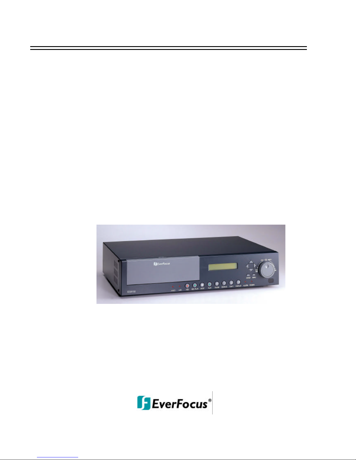
EDSR100
INSTRUCTION MANUAL
Digital Single Channel Recorder
About this manual
Before installing and using this unit, please read this Manual carefully.
Be sure to keep it handy for later reference.
V1.3


WARNING
TO REDUCE RISK OF FIRE OR ELECTRIC SHOCK,
DO NOT EXPOSE THIS APPLIANCE TO RAIN OR MOISTURE.
CAUTION
DO NOT REMOVE COVER. NO USER SERVICEABLE PARTS INSIDE.
REFER SERVICING TO QUALIFIED SERVICE PERSONNEL.
Note:
This equipment has been tested and found to comply with the limits for a Class B digital device,
pursuant to Part 15 of the FCC Rules. These limits are designed to provide reasonable
protection. This equipment generates, uses and can radiated radio frequency energy and, if not
installed and used in accordance with the instructions, may caus e harmful interference to radio
communications. However, there is no guarantee that interference will not occur in a particular
installation If this equipment does cause harmful interference to
radio or television reception, which can be determined by turnin g the equipment off and on, the
user is encouraged to try to correct the interference by one or more of the following measures:
-Reorient or relocate the receiving antenna.
-Increase these paration between the equipment and receiver.
-Connect the equipment into an outlet on a circuit different from that to which the receiver is
connected.
-Consult the dealer or an experienced radio/TV technician for hel p.
The changes or modifications not expressly approved by the party responsible for compliance
could void the user's authority to operate the equipment.
Notice:
The information in this manual was current when published. The manufacturer
reserves the right to revise and improve its products. All spec ifications are
therefore subject to change without notice.
Safety Warning

n Refer all work related to the installation of this product to qualified service
personnel or system installers.
n Do not block the ventilation opening or slots on the cover.
n Do not drop metallic parts through slots.This could permanently damage
the appliance. Turn the power off immediately and contact qualified service
personnel for service.
n Do not attempt to disassemble the appliance.To prevent electric shock,
do not remove screws or covers. There are no user -serviceable parts
inside. Contact qualified service personnel for maintenance. Handle the
appliance with care. Do not strike or shake, as this may damage the
appliance.
n Do not expose the appliance to water or moisture, nor try to operate it in
wet areas. Do take immediate action if the appliance becomes wet.
Turn the power off and refer servicing to qualified service personnel.
Moisture may damage the appliance and also cause electric shock.
n Do not use strong or abrasive detergents when cleaning the appliance
body.Use a dry cloth to clean the appliance when it is dirty. When the
dirt is hard to remove,use a mild detergent and wipe gently.
n Do not overload outlets and extension cords as this may result in a risk of
fire or electric shock.
n Do not operate the appliance beyond its specified temperature, humidity
or power source ratings. Do not use the appliance in an extr eme
environment where high temperature or high humidity exists. Use the
appliance at temperature within 0oC ~ +50oC and a humidity below 90%.
The input power source for this appliance is AC90~265V.
Safety Precautions
Safety Precautions
The exclamation point within an equilateral triangle is
intended to alert the user to presence of important operating
and maintenance(servicing)instructions in the literature
accompanying the appliance.
Warning :
To prevent fire or shock hazard, do not expose units not
specifically designed for outdoor use to rain or moisture.
Safety Precautions
The lightning flash with an arrowhead symbol, within an
equilateral triangle, is intended to alert the user to the presence
of uninsulated ” dangerous voltage” within the product’s enclosure
that may be of sufficient magnitude to constitute a risk of electric
shock to persons
Attention:
Installation should be performed by qualified service personnel only
in accordance with the National Electrical Code or applicable local codes.
Power Disconnect:
Units with or without ON-OFF switches have power supplied to the unit
whenever the power code is inserted into the power source; however, the
unit is operational only when the ON-OFF switch is in the ON position.
The power cord is the main power disconnect for all units.
External Power Supplies
Use only the recommended power supplies.
Power supplies must comply with the requirement of
the latest version of IEC 60065/CNS 13439. Substitutions
may damage the unit or cause a fire or shock hazard
110V,60Hz Power Cords
110V,60Hz power cords, input and output, must comply with
the latest versions of IEC 60065/CNS 13439
Warning:
Electrostatic-sensitive device. Use proper
CMOS/MOSFET handing precautions to avoid
electrostatic discharge.
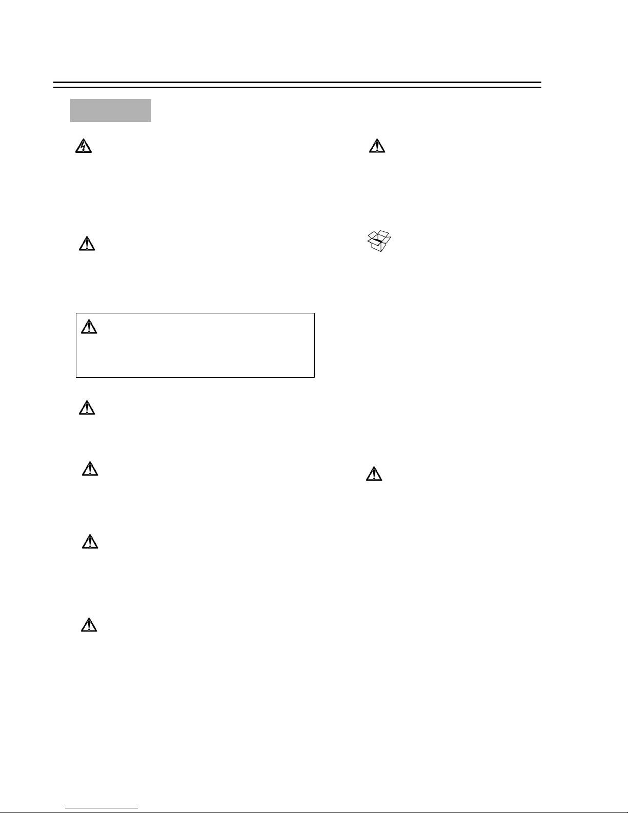
UNPACKING
Unpack carefully.
This is electronic equipment and should be
handled carefully.
Check to ensure that the following items are included;
•1. EDSR100
•2. User’s manual
•3. CF card
•4. Power Cord
If an item appears to have been damaged in shipment,
replace it properly in its carton and notify the shipper.
If any items are missing, notify your
Everfocus Electronics Corp. Sales Representative or
Customer Service. The shipping carton is the safest
container in which the unit may be transported.
Save it for possible future use.
Service
If the unit ever needs repair service, the customer
should contact the nearest Everfocus Electronics Corp.
Service Center for return authorization and shipping
instruction.
Safety Precautions

Important Safeguards
Read Instruction---All the safety and operating instructions should be read before the init is operated
Retain Instructions---The safety and operating instructions should be retained for future reference.
Heed Warnings —All warnings on the unit and in the operating instructions should be adhered to.
Follow Instructions —All operating and use instructions should be followed
Cleaning —Unplug the unit from the outlet before cleaning. Do not use liquid cleaners or aerosol cleaners.
Use a damp cloth for cleaning
Attachments—Do not use attachment not recommended by the product manufacturer as they may cause hazards.
Water and Moisture —Do not use this unit near water-for example, near a bath tub, wash bowl, kitchen sink,
or laundry tub, in a wet basement, near a swimming pool, in an unprotected outdoor installation, or any area which is
classified as a wet location.
Servicing —Do not attempt to service this unit yourself as opening or removing covers may expose you to dangerous
voltage or other hazards. Refer all servicing to qualified service personnel.
Power Cord Protection —Power supply cords should be routed so that they are not likely to be walked on or pinched by
items placed upon or against them, playing particular attention to cords and plugs, convenience receptacles, and the point
where they exit from the appliance.
Object and Liquid Entry —Never push objects of any kind into this unit through openings as they may touch dangerous
voltage points or short-out parts that could result in a fire or electric shock, Never spill liquid of any kind on the unit.
Important Safeguards

Table of Contents
1. Product Overview ………. …...…………………………………………………………………………………….. ………….. 1
1.1 Feature ………...……. ……. …. ……………………………………. ………….. ……………………………………………..1
1.2 Specifications ……….... …………………. ……………………………….. …………. ……………………………………...2
2. Front & Rear Panels ………...……. ……………………………………….. …………………………………………………....3
3. Back Panel Connections ……. ………...…………………………………….. …………………………………………………..6
4. System Connection….... ………………………...………………………….. ……………. ……………………. ………………..9
4.1 One Camera Connection …………. ….. ……. ……………………………………………………….. ……………………….9
4.2 Multiplexer Connection... ………. …. ……………………………………………………………...………………………..10
4.3 Quad Connection ( with VCR ) …………. ………………. ……………………………………….. ……………………… 11
4.4 Quad Connection ( without VCR) …. …. …………. ……………...……………………………………………………...….12
5. Installation ………...……………………………………………….. ………………. …. ……………………………………….13
6. Menu ………...………………. …………………………………….. ……………………………………………………………14
6.1 Clock/Language Setup …... …………. …………. ……. …………………………………………………………………….15
6.2 Timer-Set Setting Menu.. …………………...……. ………. ………………………...……………………………………...16
6.3 Normal Record Setting Menu ………………. ….. …………………………………………………...………………….. ….18
6.4 Alarm Record Setting Menu ……………………. ……….. ……………………………………………………………...….20
6.5 Buzzer Setting Menu ……………………. …………………………………………………………. ………………………22
6.6 Archive Setting Menu …………………...…. ……………. …………………………...…………………………………….23
6.7 Network Setting Menu …... …………………………………….. ……………………………………………………………24
6.8 System Setting Menu …………………………………………………………………………………………………………26
7. Recording …... ……………...…………………………………………………………….. ……………………………………. 28
7.1 Instant Recording …………….. ……………………………………………………. ……………………………………... 28
7.2 Alarm Recording ………………………………………………………………………………. ………………………….. 29
8. Playback …... ……………………………………………………. ………………………. ………………………………….. … 30
8.1 Normal Playback …………………………………………………………………………………………………………... 30
8.2 Search Playback ……………………………………………………………………………………………………………32
9. Copy………...………………………. ……………………………………………………………. ……………………. ………35
9.1 Still Image Copy ……………………………………………………………………………………………………………35
9.2 Copy to Movie File ……...………………………………………………………………………………………………….36
10. Interface Specifications …….. …. ……...……………………………………………………………………………………...38
10.1 Transmission setting …….. …………………………….. …………………………. ………………………………………38
10.2 Remote Control Protocol………………………………….. ……………………………………………………….. ……..39
11. Remote Controller …………. ……. ……………………………………………………………………………...……………40
12. Appendix-A/Time Lapse Mode Recording Time ……. …….. ……………………………………………………….... ….....41
12.1 Recording with and 80 GB HDD…..…………...…………………. ……………………………………………. ………..41
12.2 Recording with and 160 GB HDD………….. …………………………………………………………………………….42
13. Appendix-B/ Security Lock setting.. …... ……. ………………………………………………………………………………43
14. Appendix-C/ View From Internet/Intranet ………. …...………………………………………………………………. ……44

1. Product Overview
The EDSR100 single channel digital video recorder is the first true VCR replacement designed particularly for
the security industry, seamlessly combining high-resolution video multiplexing and digital recording.
TheEDSR100 can record at speeds up to 60/50 images per second with NTSC/PAL formats and replay event
instantly.
The EDSR100 incorporates all the benefits of digital video recording, is simple to install, and operates just like
a VCR. The highly efficient compression technology, as well as the superior clarity and detail of recorder images,
make the EDSR100 stand out from its competitors as the best choice for security surveillance.
1.1 Features
Product Overview and Features
1
Digital Recording provides superior quality images
Hard disk hot-swapping capability
Pre-Alarm image recording
Compatible with most multiplexers
Time lapse and real time recording
Refresh rate up to 60 field (50 field for PAL)
Quick Search by date/time, alarm events, and recording list
Fast and slow playback of recorded video in various speeds
On-screen setup menu and system timer
Multi-level password protection
RS-232 communication port
Highly stable Non -PC based proprietary system
Built-in M-JPEG compression/decompression with configurable quality
Audio recording capability
Programmed with various time-lapse speeds, Data can be stored in Compact Flash Card.
Operation status record log
n
n
n
n
n
n
n
n
n
n
n
n
n
n
n
n

Specifications
2
0℃~+50℃Operating Temperature
430mm (L) x 88mm (W) x 300mm (H) Dimension
AC90~265V Power Source
9-pin female connector RS-232
Yes Watch Dog Timer
Built-in real time clock Timer
Front Panel Keypad User Input Device
Menu Driven User Interface
On screen display setup Setup
Date/Time or Event Playback Search
60/50 field per second for NTSC/PAL Playback Rate
60/50 field per second for NTSC/PAL Recording Rate
Continuous, Time-lapse recording,
Timer or Event Recording
Recording Mode
3.5” IDE type, Hot- swappable Hard Disk Storage
Yes Event Log
RJ45 connector Ethernet
Yes Video Loss Detection
2 input; 2 output
1.3Vpp/1M ohm
Audio
Audio input level
Yes Alarm Output
Yes Alarm Input
Yes, Built-in Compact Flash card slot CompactFlash Memory
720x484 (NTSC); 720x576 (PAL) Video Resolution
M-JPEG Video Compression
1 video output (BNC), 1Vpp/75ohm;1S -Video output Video Output
1 video input with loop through (BNC),
1Vpp/75ohm;1S-Video input
Video Input
1.2 Specifications
Power Consumption
39W
1
35
4
2 76 8
9
10
11 12
13
14
15
1617
18
19
20
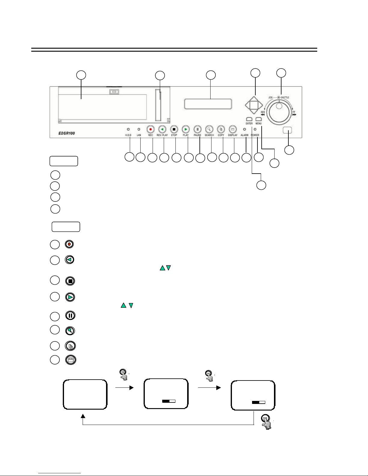
Front Panel Keypads
HDD : HDD Access, the LED will lit when HDD is accessed.
LAN : LAN Access, the LED will lit when LAN is accessed.
ALARM : The LED will lit when alarm occurs.
LED
1
2
3
POWER : Indicate the power is normal.
4
STOP : Press this key to stop Recording and Playing Back.
PLAY: Playing Back. The playback speed is shown on the LCD display,
and press to change the speed if necessary.
PAUSE: Press this key to pause the playback picture.
SEARCH: Press this key to enter the Search Menu.(please see page32)
Display: Press this switch ON/OFF the display.
6
5
7
8
9
11
12
REV. PLAY : Reverse Play Back. The playback speed is shown on the LCD
display, and press to change the speed if necessary.
10
REC : Press this key to start recording.
COPY: Press this key to start copy still picture or video stream into Compact Flash card.
Display OFF
Display Date/Time and
HDD available space
Display Date/Time
HDD available space
Recording setting
Disk size
Play position
2002/04/24 WED 12:00:00
50 %
Buzzer : Enable
Disk Size (GB) : 80.01
Record Position : 50%
Play Position : 49%
Record Quality : STANDARD
2002/04/24 WED 12:00:00
50 %
3
2. Front Panel Keypads
Keys

MENU : Press this key to enter Setup menu.
ENTER : Press this key to confirm the selection or data changed.
13
14
Remote Control
15
Jog and Shuttle Dial
Shuttle Dial : In Playback mode, turn shuttle dial can fast
forward/rewind the picture.
In Pause mode, turn shuttle dial can slow forwards/rewind
the picture.
In Menu mode, turn shuttle dial can chan ge menu page
forwards/rewind.
Jog Dial :
16
Up/ Down : (1) In Menu mode, press those keys to change data.
(2) In Record/Playback mode, press those keys to change the Record/Playback
speed.
Left/ Right : In Menu mode, those keys are used to move cursor.
17
2002/04/24
12:00:00
STANDARD
002 HR
In Standby mode, the date/time is current date/time and the
right part shows the quality and rate setting for normal
recording.
18
LCD Display
Front Panel Keypads
4
IR Remote receiver
2002/04/24
12:00:00
SYS LOAD
002 HR
Switch on the power, “system loading ”will be shown 10
seconds, both in LCD display & Main monitor.
In Pause mode, turn the jog dial can forwards/rewind the
Picture by one field.
In Menu mode turn the jog dial clockwise, for increase the cursor
data which show on the system. Turn the jog dial counterclockwise,
for decrease the cursor data which show on the system.

20
Compact Flash Card Slot: Insert a Compact Flash Card.
Hard Disk Tray: Hard Disk holder for HDD.
2002/04/24
12:00:00
RECORD
. 002 HR
In Recording mode, the date/time is current date/time and the
right part shows RECORD and current recording rate.
2002/04/24
12:00:00
PLAY
> 002 HR
In Playback mode, the date/time is the playback date/time and
the right part shows PLAYBACK and current playback rate.
19
Front Panel Keypads
5
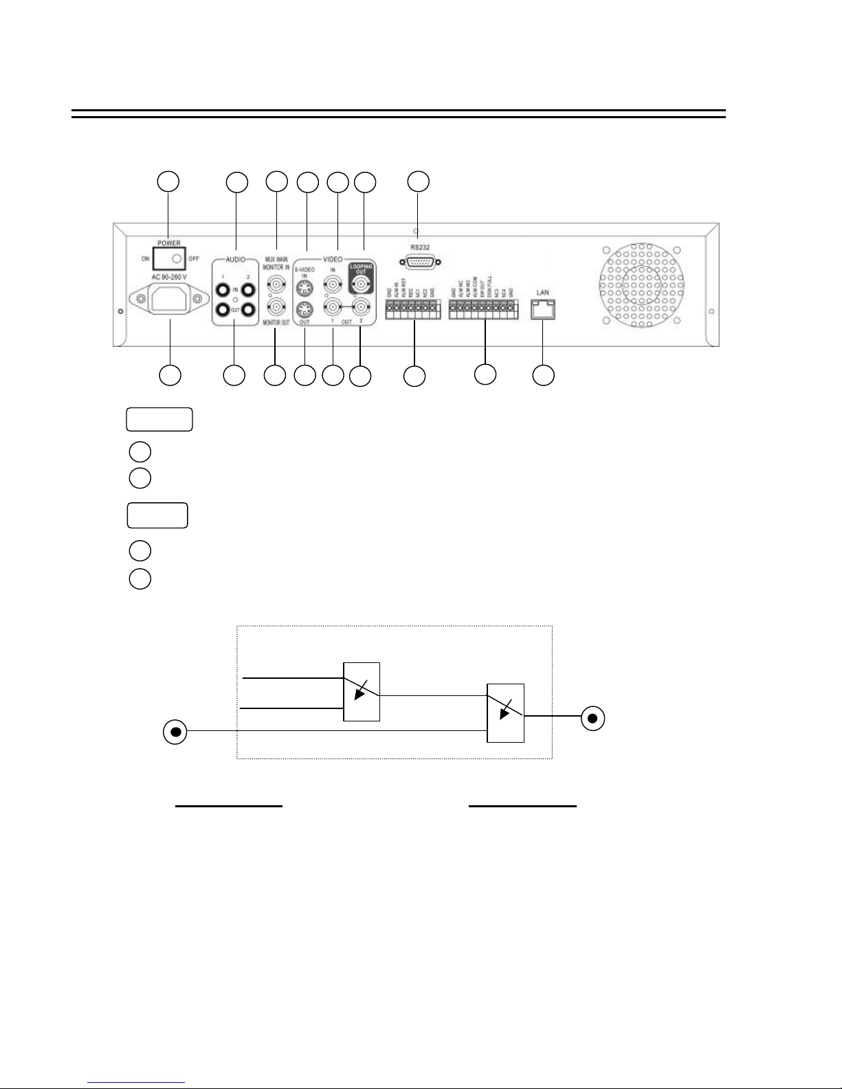
Back Panel Connections
Audio IN 1, 2 : Audio input for recording.
Audio OUT 1, 2 : These two audio outputs can be set enable or disable in Setup Me nu.
The operation of audio out is as follows:
When in recording or standby mode, the out of
SW1 is connected to Audio IN.
Playback Audio
When in playback mode the out of SW1 is
connected to SW2 Audio.
When Playback Audio is ENABLE then the output
of SW2
will be connected to Playback Audio.
When Playback Audio is DISABLE then there is
no audio output (MUTE).
When Audio Out is ENABLE and machine is in Recording or Standby mode, the Audio IN is loop-through to Audio
Out connector.
When Audio Out is ENABLE and machine is in Playback mode then the Audio Out playback audio.
AUDIO
1
3
5
7 8 12
4 6 9 10 11
13
14
15
16
2
1
Power Switch: To switch ON/ OFF the main power.
2
Main Power plug: The main power input.
3
4
POWER
Operation of SW1 :
Operation of SW2 :
Audio IN
Audio OUT
OFF / Mute
SW1
SW2
A
( Internal circuit )
6
3. Back Panel Connections

S -VIDEO IN: The S -VIDEO input connector.
VIDEO IN: The composite video input connector.
VIDEO Input to be Recorded
VIDEO Output
S -VIDEO OUT : The S -VIDEO output connector.
VIDEO OUT(1) : The composite video output connector.
VIDEO OUT(2) : Augment composite video output connector.
VIDEO LOOPING : The loop-through composite video input, could be connected to other devices.
MUX MAIN MONITOR : Video input BNC connector, connected to multiplexer main monitoroutput.
MONITOR : Video output BNC connector connected to main monitor.
MUX MAIN
MONITOR
MONITOR OUT
INTERNAL
VIDEO
SW3
A
When the machine is in Menu, Search or Copy mode, the internal Video is switched to Monitor Out, so that the user
can view full screen OSD. In other mode, the Video from multiplexer main monitor will be loop-through to the Monitor Out.
MONITOR
5
6
7
8
9
10
11
12
Back Panel Connections
7
( Internal circuit )

LAN Connector : Connect to the RJ-45 LAN connector.
LAN
ALM-NC : Normal Close Alarm output. In normal condition, this terminal is
shorted to the terminal of ALM-COM. In alarm status, it is open
between ALM-NC and ALM-COM terminals.
ALM-NO : Normal Open Alarm output. In normal condition, this terminal is
open from the terminal of ALM-COM. In alarm status, those two
terminals are shorted.
ALM-COM : Alarm Common Contact.
SW OUT : Step signal to synchronize the machine and multiplexer.
DISKFULL : Disk-Full alarm signal.
Alarm Output
14
Alarm Output Terminal Block
15
RS232
RS232 connector : Connect D-Sub 9 pins connector to RS232 ports for remote control16
Back Panel Connections
8
ALM-IN : Normal Open or Normal Close type alarm sensor input.
The Alarm Input can be selected as Normal Open or Normal Close input in the setup
menu. When an alarm occurs, alarm recording will automatically start.
ALM-RST : Normal Open or Normal Close type alarm reset input to reset the alarm.
REC : External Recording request signal. The machine will start recording when a High Level
is applied on this input terminal. If the machine is not in the timer, recording mode,
the machine will stop recording when the REC signal drops from High to Low level.
Alarm Input
13
Alarm Input Terminal Block
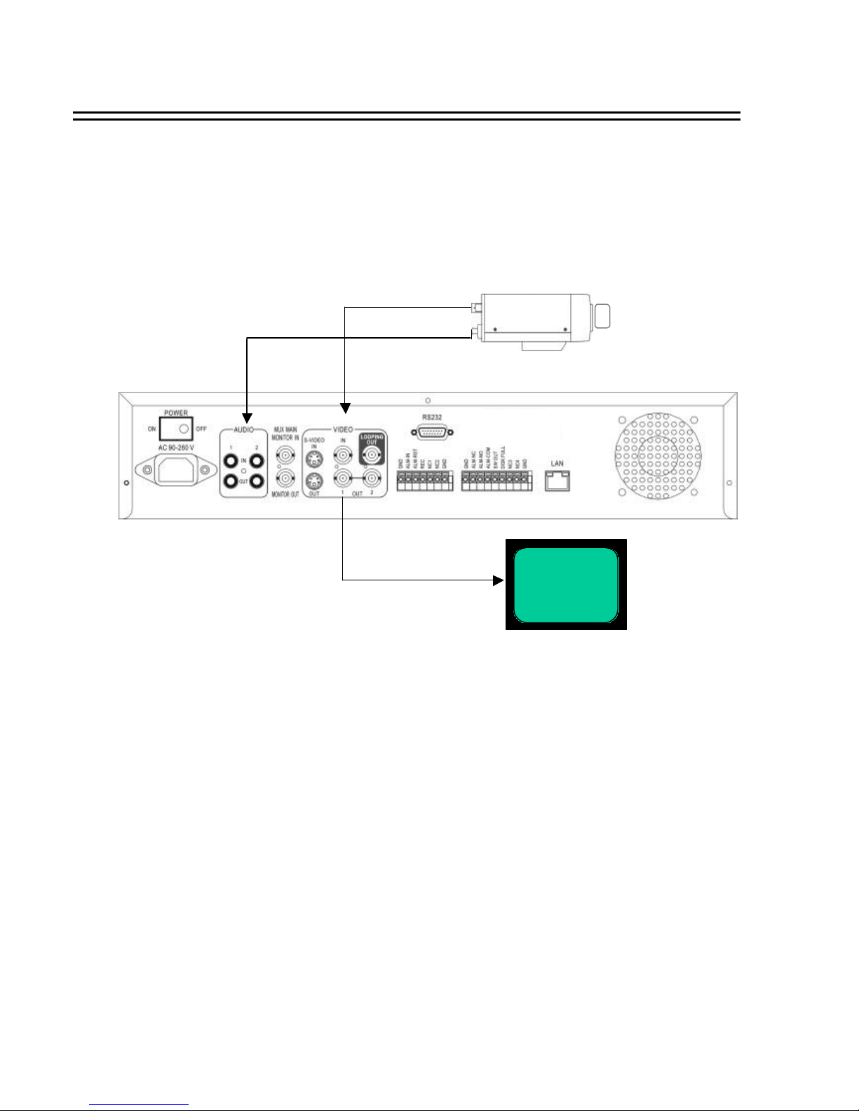
4.1 One Camera Connection.
(1 ) :Video or S -VIDEO out:
When the camera output is composite, the connect to the video input, BNC connector.
The video input setting should be set as COMPOSITE. (SY STEM SETTING MENU)
When the camera output is S-VIDEO, connect to the S-VIDEO input.
The video input setting should be set as S-VIDEO. (SYSTEM SETTING MENU)
Main Monitor
(2 ) : Audio Out:
The camera audio output is connected to the audio input terminal at the rear panel.
(3) : System Main Monitor Output:
The main monitor is connected to the VIDEO OUT 1 BNC connector or S-video
output S-connector.
System Connection
(1)
(2)
(3)
9
(4) : Please set the Multiplexer item to OFF . (NORMAL RECORD SETTING MENU)
4. System Connection
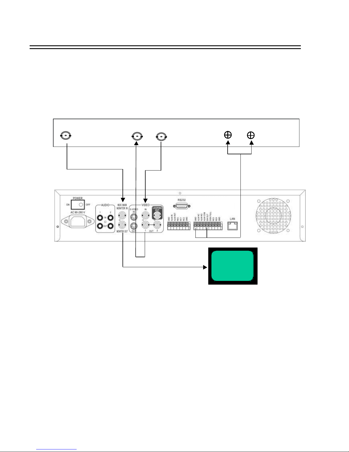
(1): Multiplexer VCR Out :
Connected to the VIDEO IN connector at the rear panel.
(2) :Multiplexer VCR In :
Connected to the VIDEO OUT 1 connector at the rear panel.
(3) :Multiplexer Main Monitor Output:
Connected to the MUX. MAIN MONITORIN IN connector at the rear panel.
(4) :Step Signal:
This signal is used to synchronize the multiplexer and the video recorder.
(5) :System Main Monitor Out:
Connect the MAIN MONITOR OUTPUT connector to the main monitor.
System Connection
10
4.2 Multiplexer Connection.
Main Monitor
Multiplexer
(3)
(4)
(2)
(1)
(5)
VCR IN
VCR OUT
MAIN MONITOR OUTPUT
STEP Signal
GND
(6) : Please set the Multiplexer item to ON . (NORMAL RECORD SETTING MENU)
 Loading...