

EverFocus EAN Series, EAN312, EAN3220, EAN3300 User Manual
EAN Series
IP Box Camera
User’s Manual
* Lens not included.
Copyright © EverFocus Electronics Corp,
Release Date: March, 2013

Copyright 2013 EverFocus Electronics Corp.
All rights reserved. No part of the contents of this manual may be reproduced or transmitted in any form or by
any means without written permission of the EverFocus Electronics Corporation.
EverFocus
12F, No.79, Sec. 1, Shin-Tai Wu Road,
Hsi-Chih, Taipei, Taiwan
TEL: +886 2 2698 2334
FAX: +886 2 2698 2380
www.everfocus.com.tw
March, 2013

About this document
All the safety and operating instructions should be read and followed before the unit is operated. This
manual should be retained for future reference. The information in this manual was current when
published. The manufacturer reserves the right to revise and improve its products. All specifications are
therefore subject to change without notice.
Regulatory Notices
FCC Notice "Declaration of Conformity Information"
This equipment has been tested and found to comply with the limits for a Class
A digital device, pursuant to part 15 of the FCC Rules. These limits are designed to provide reasonable
protection against harmful interference in a residential installation. This equipment generates, uses and
can radiate radio frequency energy and, if not installed and used in accordance with the instructions,
may cause harmful interference to radio communications. However, there is no guarantee that
interference will not occur in a particular installation. If this equipment does cause harmful interference
to radio or television reception, which can be determined by turning the equipment off and on, the user
is encouraged to try to correct the interference by one or more of the following measures:
- Reorient or relocate the receiving antenna.
- Increase the separation between the equipment and receiver.
- Connect the equipment into an outlet on a circuit different from that to which the receiver is
connected.
- Consult the dealer or an experienced radio/TV technician for help.
Warning: Changes or modifications made to this equipment, not expressly approved by EverFocus or
parties authorized by EverFocus could void the user's authority to operate the equipment.
This device complies with part 15 of the FCC Rules. Operation is subject to the following two conditions:
(1) This device may not cause harmful interference, and
(2) This device must accept any interference received, including interference that may cause undesired
operation.
EverFocus Electronics Corp.
12F, No. 79, Sec. 1, Shin-Tai Wu Rd., Hsi-Chi,
Taipei Hsien, Taiwan, R.O.C.
EAN series cameras comply with CE and FCC.

ii
Precautions
1. Donotinstallthecameranearelectricormagneticfields.
InstallthecameraawayfromTV/radiotransmitters,magnets,electricmotors,transformersand
audiospeakerssincetheelectromagneticfieldsgeneratedfromthesedevicesmaydistortthevideo
imageorotherwiseinterferewithcameraoperation.
2. Neverdisassemblethecamerabeyondtherecommendationsinthismanualnorintroduce
materialsotherthanthoserecommendedherein.
Improperdisassemblyorintroductionofcorrosivematerialsmayresultinequipmentfailureorother
damage.
3. Trytoavoidfacingthecameratowardthesun.
Insomecircumstances,directsunlightmaycausepermanentdamagetothesensorand/orinternal
circuits,aswellascreatingunbalancedilluminationbeyondthecapabilityofthecamerato
compensate.
4. Keepthepowercordawayfromwaterandotherliquidsandnevertouchthepowercordwithwet
hands.
Touchingawetpowercordwithyourhandsortouchingthepowercordwithwethandsmayresult
inelectricshock.
5. Neverinstallthecamerainareasexposedtooil,gasorsolvents.
Oil,gasorsolventsmayresultinequipmentfailure,electricshockor,inextremecases,fire.
6. Cleaning
Forcameraswithinterchangeablelenses,donottouchthesurfaceofthesensordirectlywiththe
hands.Uselenstissueoracottontippedapplicatorandethanoltocleanthesensorandthecamera
lens.Useadampsoftclothtoremoveanydirtfromthecamerabody.Pleasedonotusecomplex
solvents,corrosiveorabrasiveagentsforcleaningofanypartofthecamera.
7. Donotoperatethecamerabeyondthespecifiedtemperature,humidi
tyorpowersourceratings.
Usethecameraattemperatureswithin‐40°C~55°C/‐40°F~131°F(12VDC)or‐20thecameraat
temperatureswi;thisdeviceisnotratedassubmersible.Theinputpowersourceis12VDC/PoE.Be
suretoconnecttheproper+/‐polarityandvoltage,asincorrectpolarityortoohighavoltagewill
likelycausethecam
eratofail,andsuchdamageisnotcoveredbythewarranty.Theuseofproperly
fusedorClass2powerlimitedtypesuppliesishighlyrecommended.
8. Mounting
Usecareinselectingasolidmountingsurfacewhichwillsupporttheweightofthecameraplusany
wind,snow,iceorotherloading,andsecurelyattachthecameratothemountingsurfaceusing
screwsandanchorswhichwillproperlysupportthecamera.Ifnecessary(e.g.whenmountingto
dropceilings)useasafetywiretoprovideadditionalsupportforthecamera.

iii
CONTENTS
1. Introduction ..................................................................................................................................... 1
2. Overview ......................................................................................................................................... 2
3. Features ........................................................................................................................................... 3
4. Installation ....................................................................................................................................... 4
4.1 Packing List ....................................................................................................................................... 4
4.2 I/O Terminal Block ........................................................................................................................... 5
4.3 Lens Installation and Adjustment .................................................................................................... 5
4.4 Top / Bottom-Mount ....................................................................................................................... 6
4.5 Basic Connection .............................................................................................................................. 7
5. Accessing the User Interface ............................................................................................................. 8
5.1 Checking the Dynamic IP Address .................................................................................................... 8
5.2 Settings for Microsoft Internet Explorer ........................................................................................ 10
5.3 Connecting the Camera to the Network ........................................................................................ 12
5.4 Live View Window .......................................................................................................................... 14
6. Playback ......................................................................................................................................... 17
6.1 Playback Window ........................................................................................................................... 17
6.2 Setting up the Playback Function .................................................................................................. 19
6.2.1 Preparing the Micro SD Card .......................................................................................... 19
6.2.2 Testing the Playback Function ........................................................................................ 19
6.3 Playing Back Using ARV Viewer ..................................................................................................... 21
7 Settings .......................................................................................................................................... 22
7.1 System Info .................................................................................................................................... 22
7.1.1 Information ..................................................................................................................... 22
7.1.2 Log ................................................................................................................................... 23
7.2 User Config ..................................................................................................................................... 24
7.2.1 Live View Config .............................................................................................................. 24
7.2.2 Recording / Snapshot ...................................................................................................... 25
7.2.3 Language ......................................................................................................................... 26
7.3 Network ......................................................................................................................................... 27

iv
7.3.1 Network .......................................................................................................................... 27
7.3.2 DDNS ............................................................................................................................... 29
7.3.3 SMTP / FTP ...................................................................................................................... 31
7.3.4 HTTPS .............................................................................................................................. 33
7.3.5 SNMP ............................................................................................................................... 37
7.3.6 Network Alarm ................................................................................................................ 37
7.4 Video .............................................................................................................................................. 38
7.4.1 Multi Streaming .............................................................................................................. 38
7.4.2 Camera ............................................................................................................................ 40
7.4.3 Advanced ........................................................................................................................ 43
7.4.4 ROI (Region of Interest) .................................................................................................. 55
7.4.5 Privacy Mask ................................................................................................................... 56
7.4.6 Schedule .......................................................................................................................... 57
7.5 Audio .............................................................................................................................................. 58
7.6 User ................................................................................................................................................ 59
7.6.1 User Information ............................................................................................................. 59
7.6.2 IP Address Filter .............................................................................................................. 61
7.7 Event .............................................................................................................................................. 62
7.7.1 Event Settings ................................................................................................................. 62
7.7.2 Motion Detection ............................................................................................................ 65
7.7.3 Tamper Detection ........................................................................................................... 66
7.7.4 Alarm I/O ......................................................................................................................... 66
7.7.5 Schedule .......................................................................................................................... 67
7.8 System ............................................................................................................................................ 68
7.8.1 Date/Time ....................................................................................................................... 68
7.8.2 Daylight Saving ................................................................................................................ 69
7.8.3 SD Card ............................................................................................................................ 69
7.8.4 Maintenance ................................................................................................................... 70
8. Upgrading Firmware Using IP Utility ............................................................................................... 72
9. Specifications ................................................................................................................................. 74
EAN Series
1
1. Introduction
The EAN series is a box-type IP camera delivering image quality of up to 3-megapixel. The EAN series
features the Wide Dynamic Range (WDR) function, which can provide clear images even under back light
circumstances where intensity of illumination can vary excessively. A built-in micro SD card slot and
Power over Ethernet (IEEE802.3af) features are also provided. You can power the camera over the
network or by connecting the camera to a 12 VDC power supply. The camera also features H.264 /
MJPEG multi-stream output for simultaneous live monitoring and high-resolution recording. Since the
EAN series conforms to ONVIF / PSIA for compatibility with other network video devices, it interoperates
with a wide variety of hardware and software systems. You can also use EverFocus Mobile Applications
to remotely view the live views of the cameras through your handheld devices; or use EverFocus CMS to
remotely manage multiple IP devices connected on the LAN or WAN. The EAN series is designed for
simple installation and supports all types of indoor mounting applications.
The EAN Series Models
Model Name Megapixel WDR
EAN3120 1.3 MP Yes
EAN3220 2 MP Yes
EAN3300 3 MP No
System Requirements
Before installing, please check that your computer meets the following system requirements.
Operating System Microsoft Windows XP / Vista (32-bit) / 7 (32-bit)
CPU Intel Core2 Duo 2 GHz or higher
RAM
1 GB or more
Additional HD space depends on required local storage of video files,
100 Mbps network card.
Screen Resolution 1024 x 768 pixels or higher, 32-bit pixel color resolution
Software
DirectX 9.0c
Microsoft Internet Explorer 7 or higher
Note: For using the Internet Explorer, some settings are required. Please refer to 5.2 Settings for
Microsoft Internet Explorer.
EAN Series
2
2. Overview
2
3
4 6
7
8
9
10
5
11
1
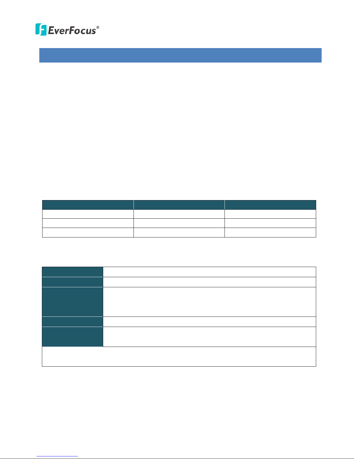
No. Item Name Descriptions
1 Memory Card Slot Insert a micro SD / SDHC card to store recording data.
2 Power LED Indicates the power is supplied.
3 12 VDC Port Connects to power.
4 Ethernet / PoE Connects to a 10/100 Ethernet or PoE.
5 Reset Button Resets all configurations to factory default.
6 I/O Terminal Block Connects I/O devices.
7 Video Out
Connects to a portable monitor for testing the camera view and
setting the focus and angle of the camera during initial
8 Audio In
Connects to a microphone for audio input. Note that microphones
with external power supplies are required.
9 Audio Out Connects to a speaker for audio output.
10 Light Sensor Detects lights.
11 Auto Iris Lens Connector Plug the Iris control cable to the connector.

EAN Series
3
3. Features
• 1/3” Panasonic CMOS sensor (for EAN3120 / 3220)
1/2.8” Sony CMOS sensor (for EAN3300)
• Triple streams (stream 1 / 2 / 3 from H.264 or MJPEG)
• Up to 30 fps at 1920 × 1080
Supports 15 fps at 2048 × 1536 (only for EAN3300)
• Auto Iris control
• Built-in micro SD / SDHC card slot
• Removable IR-cut filter for Day / Night function
• One alarm input and output
• Two-way audio
• TV-out
• Wide Dynamic Range (for EAN3120 / 3220)
• 2D / 3D Dynamic Noise Reduction (DNR)
• Motion detection
• Privacy mask
• 12 VDC / PoE
• Multi-languages on Web interface
• ONVIF / PSIA compliant
• Supports EverFocus CMS and Mobile Applications
EAN Series
4
4. Installation
4.1 Packing List
• EAN Series Camera (lens not included) x 1
• Software CD x 1
• Quick Installation Guide x 1
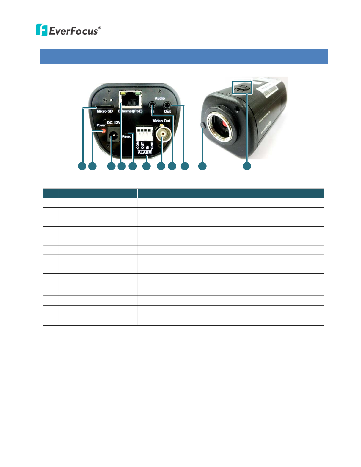
• Tool Packet x 1 (contains the following items)
- C-mount lens adapter - ¼-20 UNC thread mounting bracket and 2 screws
- Hexagon wrench - Power pigtail cable
Note:
1. Equipment configurations and supplied accessories vary by country. Please consult your local
EverFocus office or agents for more information. Please also keep the shipping carton for
possible future use.
2. Contact the shipper if any items appear to have been damaged in the shipping process.
EAN Series
5
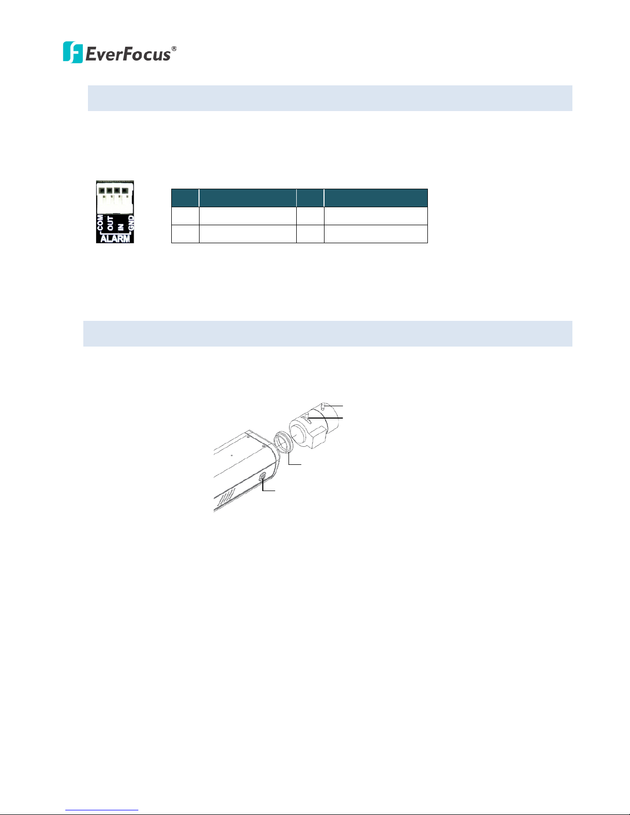
4.2 I/O Terminal Block
The I/O terminal block, located on the rear panel of the camera, can be used to develop application
for alarm input and output.
1 2 3 4
Pin Assignment
No. Function No. Function
1 Alarm COM 3 Alarm Input
2 Alarm Output 4 Digital GND
4.3 Lens Installation and Adjustment
You can install either a CS-mount or a C-mount lens into the camera. It is recommended to use a lens
with aperture ratio of F/1.4 or smaller. Please refer to the following reference steps.
C
-Mount Lens Adapter
DC Auto Iris Lens Connector
Focus Screw
Zoom Screw
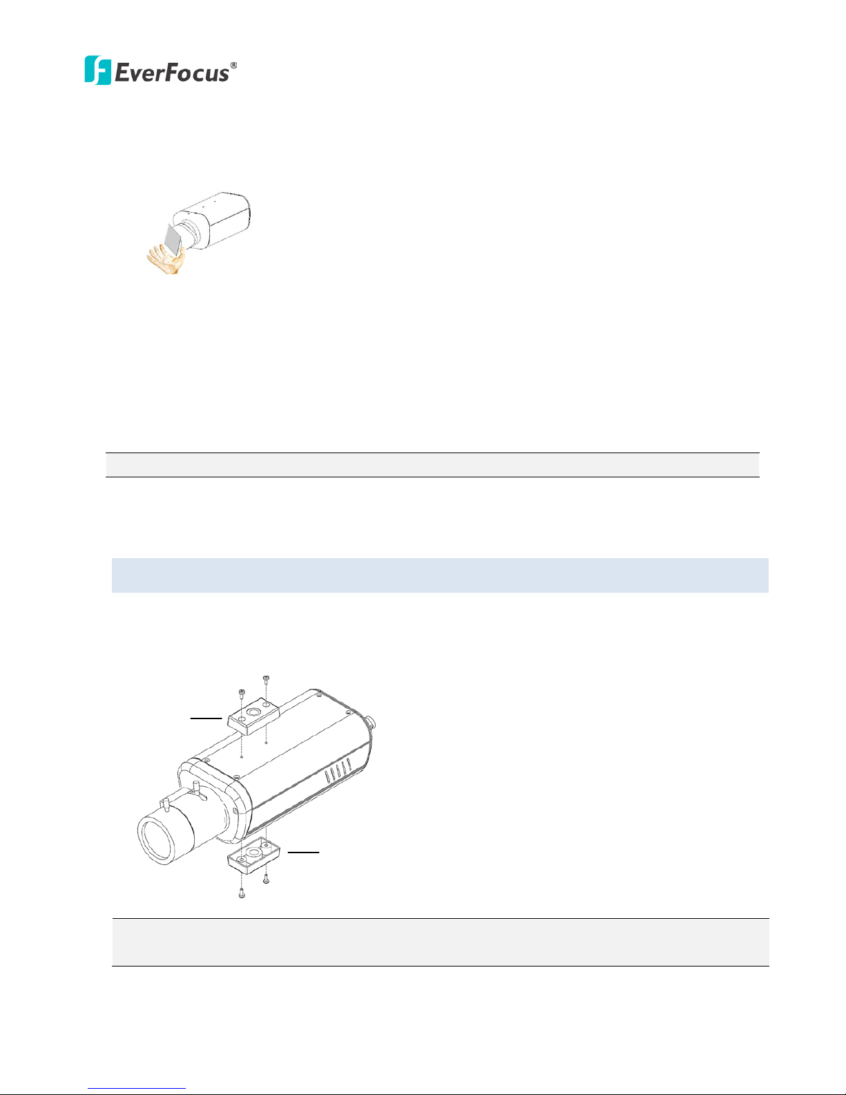
CS-Mount Lens:
1. Remove the cover cap from the camera body.
2. Install the lens into the camera body.
3. Adjust the lens using the Focus / Zoom Screws.
If you are using a DC Auto Iris lens:
1. Remove the cover cap from the camera body.
2. Install the lens into the camera body.
3. Connect the DC cable to the DC Auto Iris Lens Connector.
EAN Series
6
4. When making final focus adjustment, place the ND filter in front of the lens to force the lens iris
to open, and then adjust the lens using the Focus / Zoom Screws.
Note: To use the ND filter, remove the protective sheets from both sides of an ND filter.
5. Lock the Focus Screw and then remove the ND filter.
C-Mount Lens:
1. Remove the cover cap from the camera body.
2. Install the lens into the camera body using the supplied C-mount lens adapter.
3. Adjust the lens using the Focus / Zoom Screws.
Note: Installing a C-mount lens without the C-mount lens adapter may damage the camera sensor.
4.4 Top / Bottom-Mount
You can use the supplied mounting bracket and screw it on the top of the camera body to suspend
the camera, or on the bottom of the camera body to support the camera.
Top Mount
Bottom Mount
Note: Before mounting the EAN3300, please access the Web interface first to calibrate the iris.
Please refer to 7.4.2 Camera in the User’s Manual.
EAN Series
7
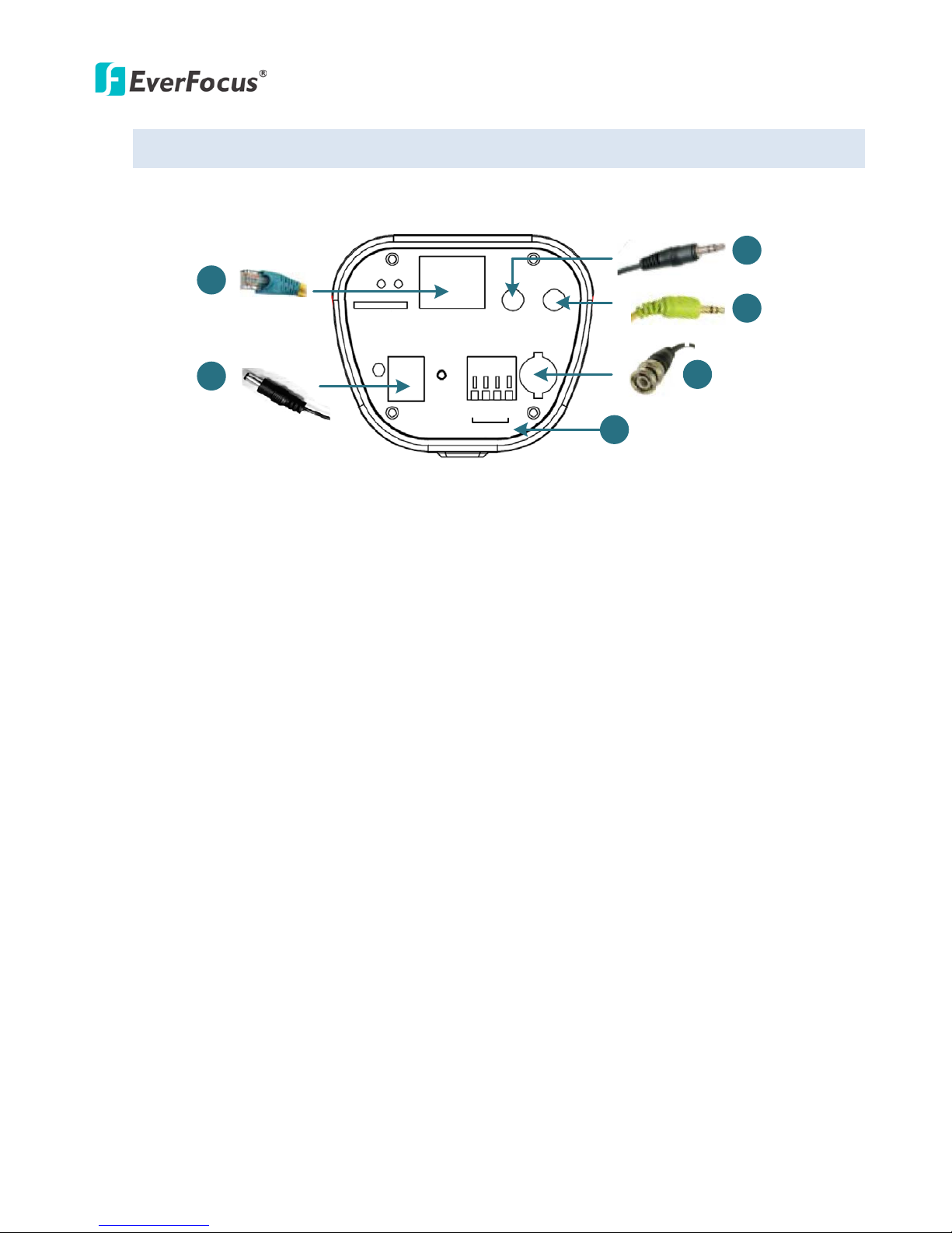
4.5 Basic Connection
Micro SD
Audio
In Out
Ethernet
(PoE)
DC 12V
Power
Reset
Video Out
COM
Out
In
GND
Alarm
1
2
3
3
4
5
1. Use a standard network cable to connect the camera to the network.
2. Connect the camera to power using one of the following methods:
• Plugging the supplied power pigtail cable to the 12 VDC port.
• Using the PoE function and the power will be provided over the network cable.
3. Optionally connect the camera to a speaker or microphone. Note that microphones with
external power supplies are required.
4. Optionally connect the camera to a monitor using a Test-Out cable.
5. Optionally connect the camera to the input / output devices.
After powering the camera, the power LED will be lit in red and you can access the live view and
adjust the image clarity.
EAN Series
8
5. Accessing the User Interface
This section explains how to access the Web interface of the camera for configuration.
5.1 Checking the Dynamic IP Address
You can look up the IP address and access the Web interface of the camera using the IP Utility (IPU)
software included in the software CD. Please connect the IP camera in the same LAN of your
computer.
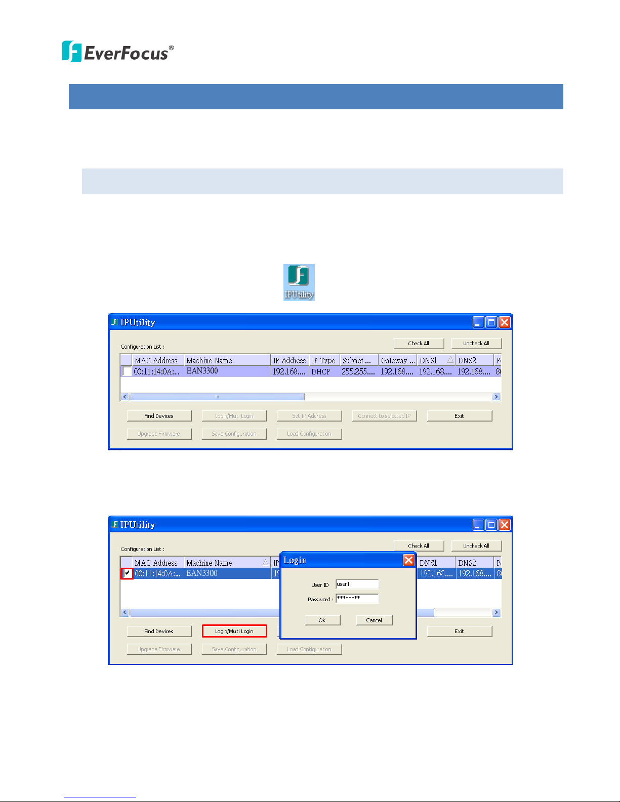
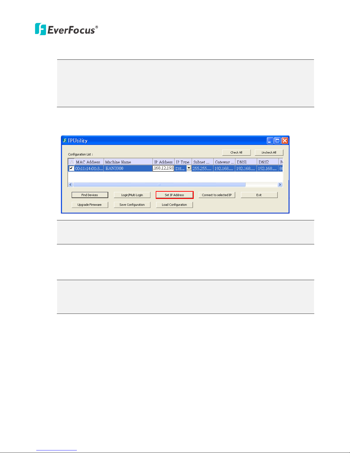
1. Install and then start the IPU program . The following dialog box appears.
2. IPU will automatically search the cameras connected in the LAN. The default network values of
the cameras will be displayed. By default, the network protocol of the camera is DHCP.
3. To configure the network settings, select a camera and then click Login/Multi Login to log in.
EAN Series
9
4. Type the user ID and password. Click OK.
Note:
1. The default user ID is user1 and the default password is 11111111.
2. If you select more than one camera that has the same user ID / password, you will be able
to log in several cameras at once.
5. To change the IP settings, double-click the values in the column and type the numbers or select
an option. Click Set IP Address to save the settings.
Note: Most networks uses DHCP to assign IP address, if you are unsure of your network
settings, please consult your network administrators for configuration details.
6. To access the camera, highlight the camera and click Connect to Selected IP. The Internet
Explorer window pops up.
7. Type the user ID and password to log in. The Live View window of the camera appears.
Note: You might be required to download ActiveX, which is required to view the camera feed.
If asked, click "Yes".
For more details on setting up the Microsoft Internet Explorer, please refer
to 5.2 Settings for Microsoft Internet Explorer.
EAN Series
10
5.2 Settings for Microsoft Internet Explorer
To enable Remote Live View, Firmware Upgrade and ActiveX Prompt on Internet Explorer, some
settings have to be complete. Please follow the steps below:
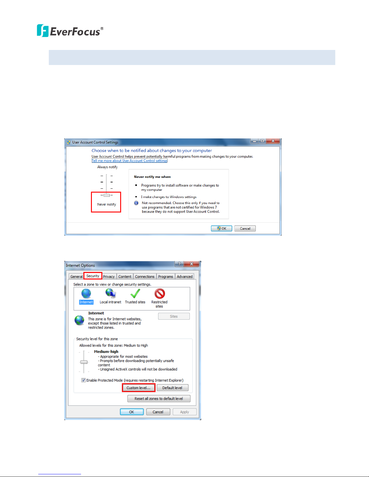
1. On the computer, click Start > Control Panel > System and Security > Action Center (click Change
User Account Control Settings), the User Account Control Settings window appears. Adjust the
slide bar to Never Notify and then click OK. Restart your computer if requested.
2. Open the Internet Explore, click Tools > Internet Options > Security Tab > Custom Level, the
Security Settings windows appears.
EAN Series
11
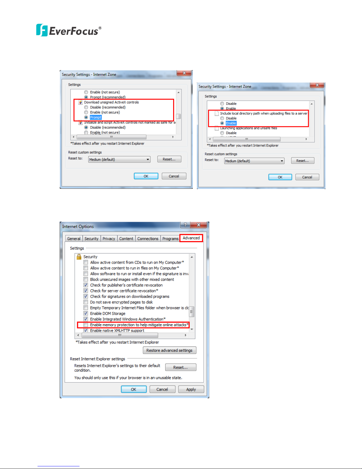
3. In the Download unsigned ActiveX controls field, select Prompt. In the Include local directory
path when uploading files to a server field, select Enable. Click OK.
4. In the Internet Options window, click the Advanced tab and then disable Enable memory
protection to help mitigate online attacks. Click OK.
EAN Series
12
5.3 Connecting the Camera to the Network
There are three methods to connect the IP camera to the network: Router or LAN Connection, Direct
High-Speed Connection and One-to-One Connection.
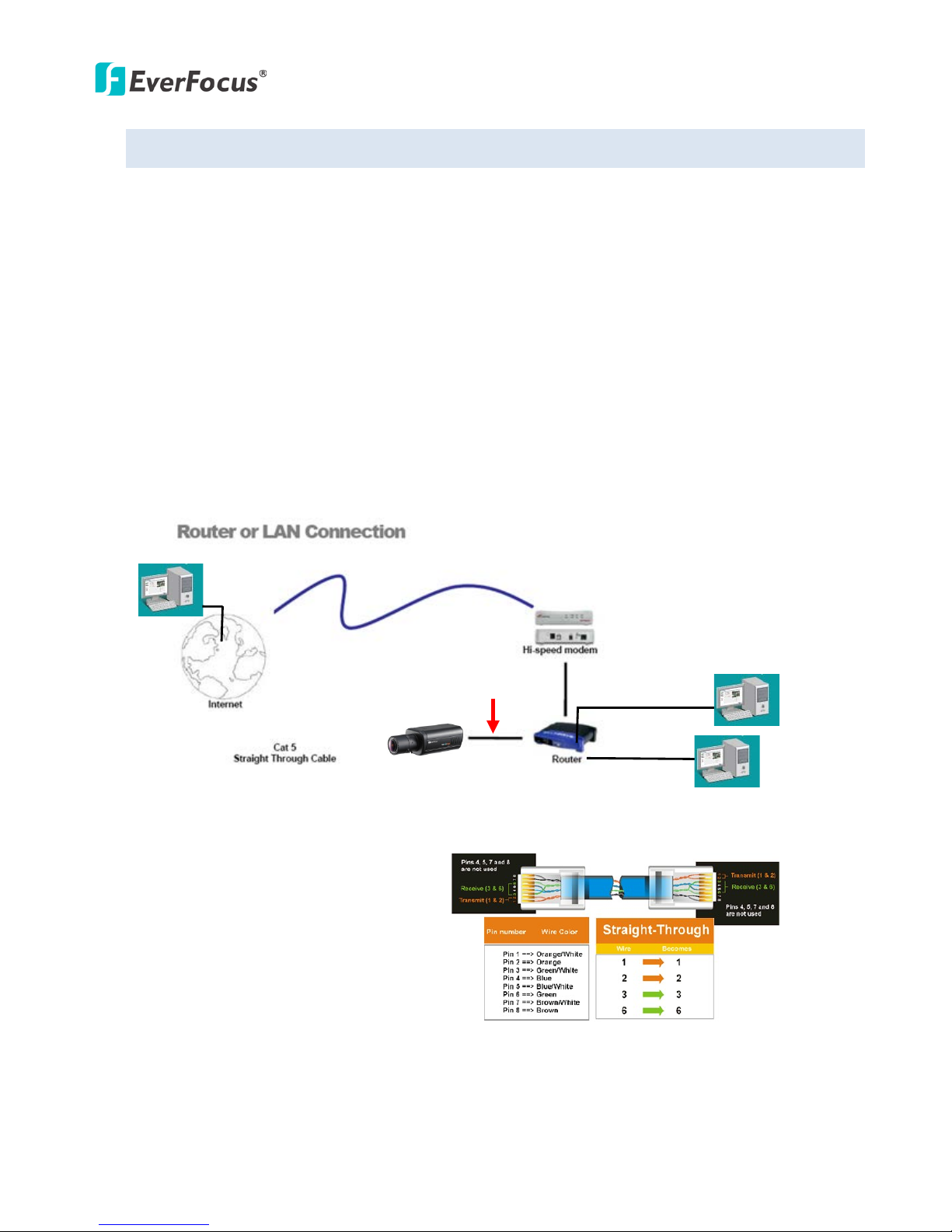
Router or LAN connection
This is the most common connection in which the IP camera is connected to a router and allows
multiple users on and off site to see the IP camera on a LAN/WAN (Internet). The camera must be
assigned an IP address that is compatible with its LAN. By setting up port forwarding on the router,
you can remotely access the cameras from outside of the LAN via the Internet. To remotely access the
Web interface of the IP camera, please refer to 7.3.2 DDNS. To set up port forwarding, please consult
the manual of the router.
Straight-through LAN patch cable
Right: Pinout of a straight-through cable.
EAN Series
13
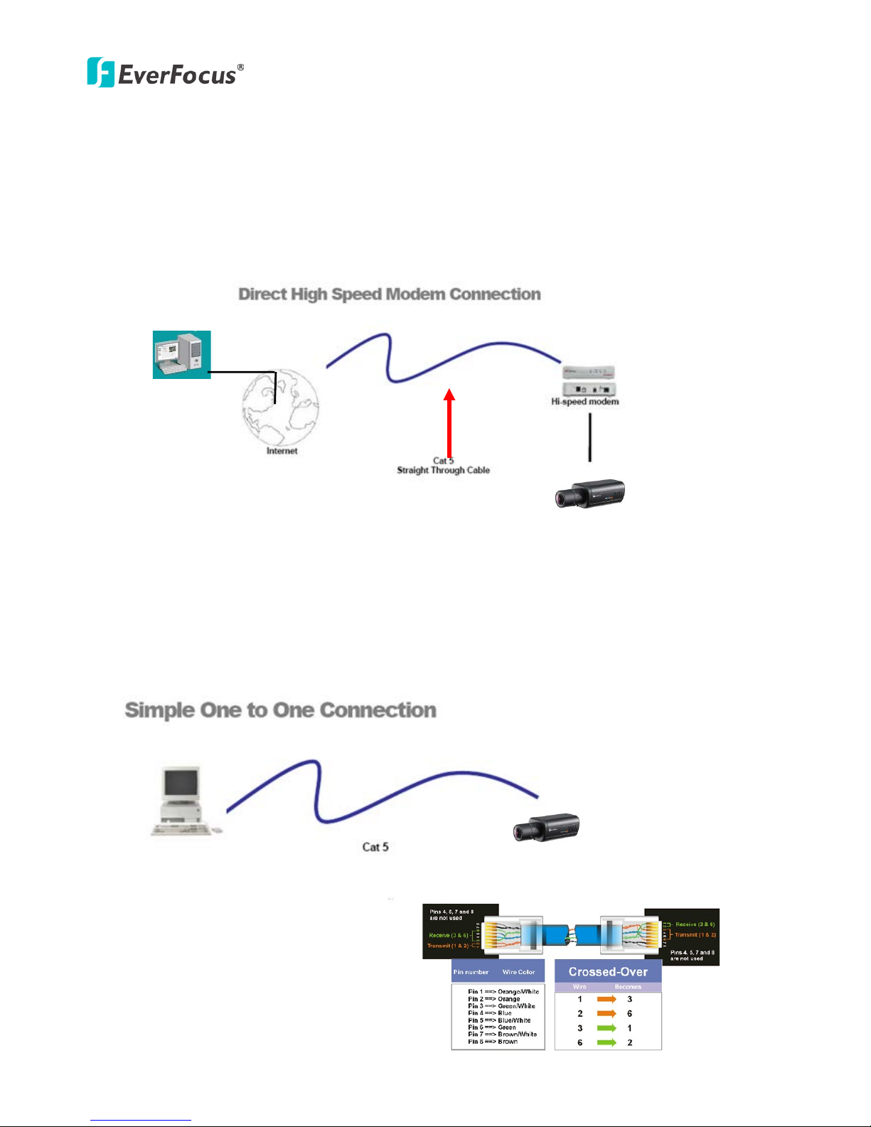
Direct High-Speed Connection
In a Direct High-Speed Connection, the camera connects directly to a modem without the need for a
router. You need to set the static or dynamic WAN IP address assigned by your ISP (Internet Service
Provider) in the camera’s configuration web pages. To access the camera, just type “http://xxx”,
where xxx is the IP address given by your ISP. If you have a dynamic IP address, this connection may
require that you use DDNS for a reliable connection. Please refer to 7.3.2 DDNS.
One-to-One Connection (Directly from PC to IP Camera)
You can connect directly without using a switch, router or modem. However, only the PC connected
to the camera will be able to view the IP camera. You will also have to manually assign a compatible IP
address to both the computer and the IP camera. Unless the PC has another network connection, the
IP camera will be the only network device visible to the PC. See the diagram below:
Pinout of straight patch cable
Right: Pinout of a crossed-over cable.
EAN Series
14
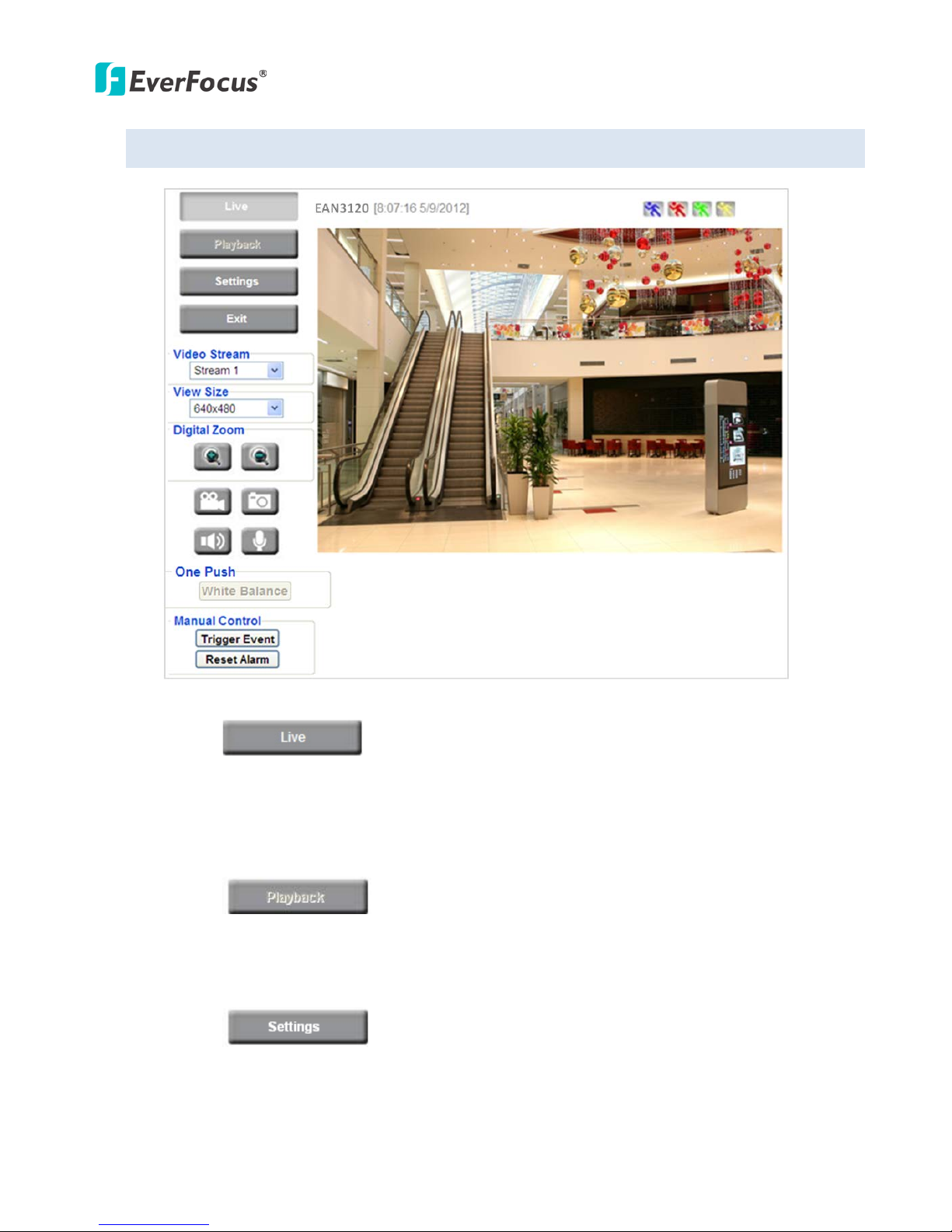
5.4 Live View Window
1. Press the button to display the "Live View" window. Double-click on the
image to show a full-screen display, double-click again or press ESC to return to the normal display.
If you experience video feed lag time (if connected via Internet), you can reduce the resolution or
limit the number of streams. See 7.4.1 Multi Streaming.
2. Press the button to play the recorded data directly from the on-camera Micro
SD / SDHC card (for this function to become active, you have to insert a Micro SD / SDHC card in the
Micro SD / SDHC card slot on the rear panel of the camera. See 7.8.3 SD Card.
3. Press the button to enter the Settings page. On the Settings page, there are
8 submenu sections: [System Info], [User Config], [Network], [Video], [Audio], [User], [Event], and
[System]. Click on the section buttons to open their configuration fields. See the Settings section
below for more information.
EAN Series
15
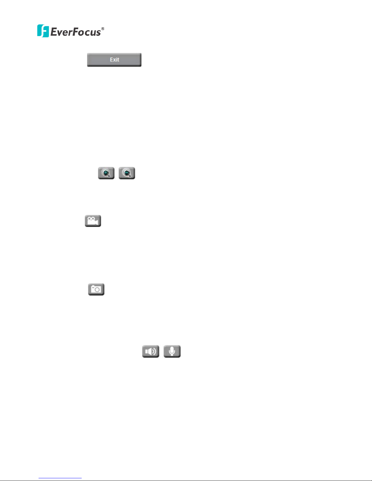
4. Press the button to exit the system and close this browser page.
5. Video Stream
Select the Video Stream (Stream 1, Stream 2 or Stream 3) that will be displayed in the video box on
the right. Stream 2 and Stream 3 are only selectable if you have enabled the stream. The default
setting is Stream 1 only. See 7.4.1 Multi Streaming.
6. View Size
Use this to select the appropriate view size and shape of the video box on the right. A smaller size
might increase transmission speed and video quality.
7. Digital Zoom
Click the Zoom In / Zoom Out buttons or roll the mouse wheel to zoom in / out the camera live view
up to 10x. Clicking on a magnified image will re-center the image around that point.
8. Record
The Record button is used to record the current video stream. Click the Record button to start /
stop recording. This icon is only for one-minute video recording. To record long-period recordings,
please set a recording schedule (See 7.7.5 Schedule). The location on your computer, where the
image files will be saved to, and file size can be specified in the submenu (see 7.2 User Config).
9. Snapshot
Click the Snapshot button to save a snapshot of the video image currently being displayed. The
location on your computer where the snapshot data will be saved can be specified in “Settings >
User Config > Recording/Snapshot” (see 7.2 User Config).
10. Play Audio / Transmit Audio
Click the “Play Audio” (speaker) and “Transmit Audio” (microphone) buttons to switch the sound
on/off for the speaker and microphone, respectively (if such external devices have been connected
to the camera directly or via the network).
EAN Series
16
11. One Push
This function is only available for EAN3120 / 3220. The One Push button can be displayed on the
live view window by enabling the Show One Push Buttons function on the User Config < Live View
Config Setting page (see 7.2.1 Live View Config). To enable the button (turned from faded to clear),
on the Video < Advanced Setting page, select One Push from the White Balance Settings Mode
drop-down list, and click the Apply button. Once this is done, pressing the One Push button on the
Live View Window will instruct the camera to adjust the white balance settings, and these settings
will be active until the button is pushed again. This is like a “semi-automatic” way to adjust white
balance to suit the user, if the Auto or Manual mode does not give the result the user wants.
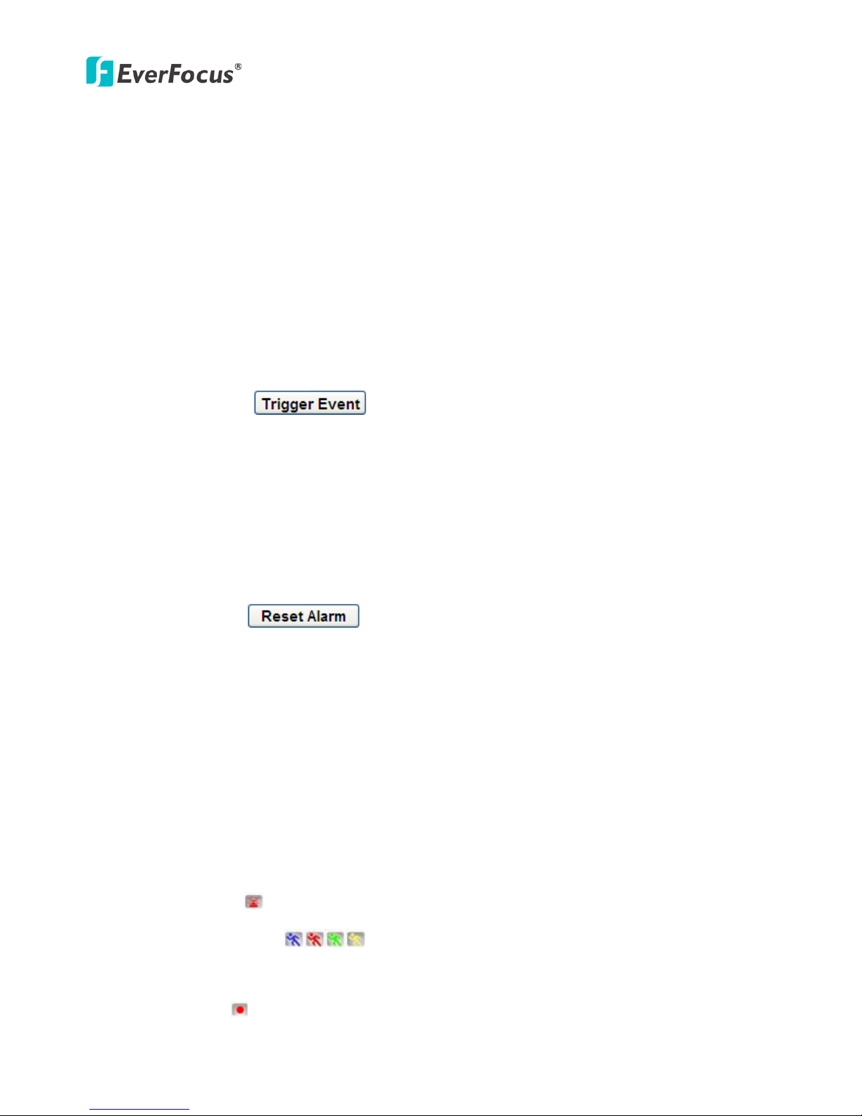
12. Manual Control
– Trigger Event
Press the “Trigger Event” button to trigger an event directly from the Live page. If you have
configured an event (in the Event submenu) that will trigger a reaction (like a recording) when a
Manual Trigger event occurs, clicking this button will trigger that reaction. You can select what that
reaction will be. You can, for instance, set the camera to record the audio/video feed to the Micro
SD card on board the camera. You can then click on the Playback button to open the Playback page
and search for and play all such recordings that had been stored on the card. Such event actions
will be effective once they have been configured in the “Event” menu (see 7.7 Event).
– Reset Alarm
Press the “Reset Alarm” button to reset the alarm output remotely.
13. Status Display (info lines that can be placed above video box or at bottom of page)
This shows the name of the camera that is currently active or being configured, current date/time
and current frame rate. You can activate these info displays in the Settings > User Config page (see
7.2 User Config).
14. Event Signal Icons (above video screen)
When an alarm or motion event is triggered, a signal icon will appear at the top right of the Live
View window to alert the user.
Alarm event icon : When an alarm is triggered, this icon appears.
Motion detection icons : The colors of these motion event icons correspond to the
colors of the motion trigger areas you have configured in the Motion Detection submenu (see 7.7.2
Motion Detection).
Recording icon : When the camera is recording to a PC-based folder, this icon appears.
EAN Series
17
6. Playback
You can remotely play back the recordings stored in the on-camera micro SD card on the Web interface,
or play back the recordings stored in the computer using the ARV Viewer included in the software CD.
Playback is designed as a quick way to check recent recordings that were triggered by Events that were
configured to “Record to SD Card” in the Settings > Event > Event Settings page (see 7.7.1 Event
Settings).
Note: Note that the Playback page is only accessible once the on-camera SD card is inserted and
active.
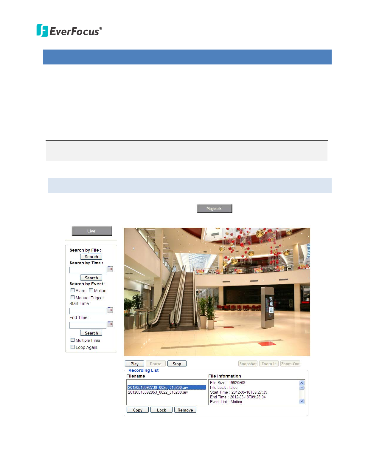
6.1 Playback Window
On the Live View Window, click the Playback button to open the Playback page.

EAN Series
18
Search by File: Click the Search button to search for all recording files on the on-camera SD card.
Search results will be displayed in the Filename area.
Search by Time: Click the calendar icon and select the date and time from which you want to search
until the present moment. Click search to get your search results, which will be displayed in the
Filename area.
Search by event: Click the type of Event recordings you want to search for (Alarm, Motion, Manual
Trigger) and then click the calendar icons to select the Start Time date/time and the End Time
date/time of your search. Click Search to get your search results, which will be displayed in the
Filename area.
Multiple Files: Check this box if you want the video player to play all the files in the selected folder.
The files will be displayed in the Filename area.
Loop Again: Check this box if you want the video player to play the selected file over and over again.
Play: Once you have opened the file’s folder and have clicked on the file to highlight it, its details will
be displayed in the File Information area. You can now click Play to play that specific file.
Pause: Click this button to pause the playback.
Stop: Click this button to stop the playback.
【Recording List】
Filename: This area will display a list of search results (recording files and folders). Folders (named
with the recorded date) will be displayed first. Click on the folder and click on each subfolder until the
recording files (.arv) in that folder is listed.
File Information: Click a file on the Filename list, the selected file information will be listed.
Copy: Click this button to copy the selected file to the computer-based folder of your choice. A
browsing box will open so that you can search for the folder of your choice. You can use the ARV
Viewer to play back the recordings recorded in your computer. For details on ARV Viewer, see 6.3
Playing Back Using ARV Viewer.
Lock: Click this button to lock the selected file. This will protect that file from being overwritten during
any overwrite procedure. The file will thus be saved on the micro SD card indefinitely. However, the
file will still be deleted if the micro SD card is ever formatted.
Remove: Click this button to delete the selected file.
EAN Series
19
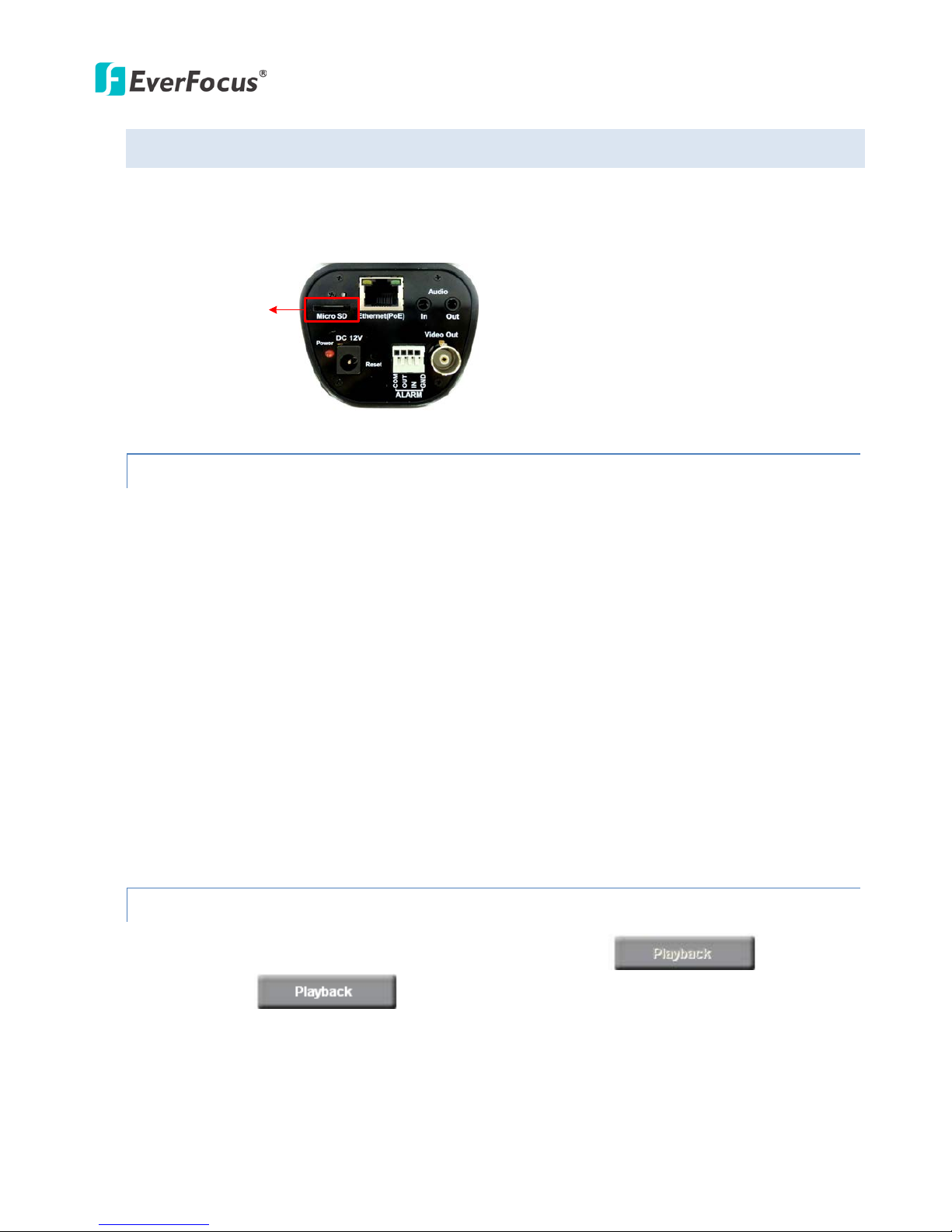
6.2 Setting up the Playback Function
Note that the Playback function will not be active until the user has inserted a micro SD card in the
camera’s micro SD card slot. The card may also have to be formatted in the Settings submenu.
Micro SD Card Slot
6.2.1 Preparing the Micro SD Card
Once you insert a functional micro SD card into the slot, the Playback button on the Live page should
become active within seconds (see section 6.2.2 below – the grey letters should turn white). IF NOT,
do the following:
1. From the Live page, click Settings > System > SD Card. If no card has been inserted yet, the
Remove button should be faded, indicating that no card is being detected. (If a card is
inserted, and the Remove button is still faded, pull the card out and re-insert it.)
2. Slide the card into the slot until it clicks into position.
3. The Remove button should become active within a few seconds, indicating the card is active.
4. If the Remove button stays faded, click the Format button to format the card. NOTE: All data
on the disk will be deleted if the Format button is clicked.
6.2.2 Testing the Playback Function
1. Once the SD card is detected by the system, the button (inactive)
will turn to (active).
2. To test the Playback function (this is not required), set up a “Manual Trigger” Recording
Event by clicking Settings > Event > Event Settings.
3. Click the “Add” button on the middle right side of the page to open an “Add Event” box.
4. Give the event a name, like “Test 1”.
 Loading...