

Page 1
Models: DHV-410M
Installation / User Manual
Four Channel
Digital Video Recorder
Version 1.2
Before attempting to connect or operate this product,
please read this manual carefully and keep it for future use.
© Copyright 2004
Page 2

1
Version 1.2
CONTENTS
■
PREFACE-------------------------------------------------------------------------------------------- 2
■ FEATURES------------------------------------------------------------------------------------------ 2
■ SPECIFICATIONS--------------------------------------------------------------------------------- 3
■ MAJOR OPERATING CONTROLS AND THEIR FUNCTIONS
1>Front View-----------------------------------------------------------------------------------------------
4
2>Rear View-----------------------------------------------------------------------------------------------
5
3>Bottom View(NTSC/PAL system SELECT)-----------------------------------------------------
6
■ MENU AND SYSTEM SETUP
1. >MENU 1
1.1> Display Camera Select--------------------------------------------------------------------------
7
1.2> Record Camera Select---------------------------------------------------------------------------
7
1.3> Record Mode Select------------------------------------------------------------------------------
8
1.4> Record Field Rate---------------------------------------------------------------------------------
8
1.5> Record Video Quality-----------------------------------------------------------------------------
8
1.6> Record Schedule----------------------------------------------------------------------------------
8
1.7> Sensor Setup
1.7.1>Post-alarm Record Time------------------------------------------------------------------------
9
1.7.2>Alarm Duration------------------------------------------------------------------------------------
9
1.7.3>Sensor Type Setti ngs----------------------------------------------------------------------------
9
1.8> Motion Detection Setup
1.8.1>Motion Det Camera Select---------------------------------------------------------------------
10
1.8.2>Motion Det Sensitivity---------------------------------------------------------------------------
10
1.8.3>Video Loss Camera Select---------------------------------------------------------------------
10
1.8.4>Video Loss Alarm---------------------------------------------------------------------------------
10
1.9> Hard Disk Drive Setup
1.9.1>Overwrite Enabled--------------------------------------------------------------------------------
11
1.9.2>HDD Format----------------------------------------------------------------------------------------
11
1.10> Next Page(Menu2)----------------------------------------------------------------------------
11
2. >NEXT PAGE (Menu2)
2.1> Password Setup---------------------------------------------------------------------------------
12
2.2> Time Setup---------------------------------------------------------------------------------------
12
2.3> Language Select--------------------------------------------------------------------------------
12
2.4> Key Tone------------------------------------------------------------------------------------------
12
2.5> Sensor Alarm Beep----------------------------------------------------------------------------
13
2.6> HDD Full Beep----------------------------------------------------------------------------------
13
2.7> Record Message Display---------------------------------------------------------------------
13
3. >SENSOR ALARM CONNECTION---------------------------------------------------------------
14
4. >HARD DISK DRIVE INSTALLATION-----------------------------------------------------------
15
5. >CONNECTING EXTERNAL HARD DISK DRIVE--------------------------------------------
16
6. >MASTER/SLAVE HARD DISK DRIVE CONFIGURATION--------------------------------
17
7. >SECURITY LOCK------------------------------------------------------------------------------------
18
■ RECORDING AND PLAYBACK
1. >PRECORDING---------------------------------------------------------------------------------------
20
2. >PLAYBACK--------------------------------------------------------------------------------------------
21
Page 3

2
Version 1.2
■
PREFACE
This is an advanced 4 channel standalone digital video recorder, that combines video
multiplexing, digital video recording in a single easy to use and install package.
It can be easily installed into your existing surveillance system since it provides 2
composited video signal outputs to connect CCTV monitor directly. The friendly operations
avoide from wasting time to familiarize yourself with extremly complicated DVRs.
■
FEATURES
1. Full Screen Recording and Playback
To record and play back the high quality full screen pictures.
2. Two Recording Modes Available – the DUAL mode and the QUAD mode
In the DUAL mode, user can monitor the live pictures or play back the recorded
pictures from single channel or all channels simutaneously. In the QUAD mode, the
live pictures or the recorded pictures are displayed in quad format only.
3. Play back at the simple touch of one button.
Users just easily press the playback key two times to start playback.
4. Extend recording time by connecting an external HDD
Besides being able to be built in a removalbe hard disk drive, the DVR can connect an
external hard disk drive to extent recording time.
5. Extend recording time through motion detection
For avoiding from unnecessary recording, users are allowed to select the cameras to
be in
motiondetection mode in channel by channel.
6. Security Lock
To restrict operating or changing the settings without permission.
Page 4

3
Version 1.2
■
SPECIFICATIONS
Item Descriptions
Video Input Format NTSC/PAL
Video Input Channel 4 channels
Video Looping Channel 4 channels
Video Output (3 outputs)
Output 1:1Vp-p/75Ω;Output2:1Vp-p/75Ω
Output 3:Y/C
NTSC Real Time
Display
PAL Real Time
Recording Rate NTSC Real Time. Adjustable
(Quad Mode) PAL Real Time. Adjustable
Recording Rate NTSC 60 fields per second/4 channel
(Dual Mode) PAL 50 fields per second/4 channel
Recording Schedule Auto Continuous/Sensor Alarm/No Recording
Resolution Display 520 TVL. NTSC: 720x480;PAL:720x576
Recording 520 TVL. NTSC: 720x480;PAL:720x576
Language English/Chinese
Simplex Yes
Compression Format MJPEG
Hard Disk (IDE type)
120GB HDDx2 in maximum
(1 internal HDD and 1 external HDD)
Back-up (Archive Device) Removable HDD, VCR
Search Date,Time,camera
Playback Speeds 1x, 2x, 4x, 8x
Post-alarm Recording Duration 30/25/20/15/10/5 Secs.
Alarm Duration Continous/30/25/20/15/10/5/0 Secs.
Alarm In/Out 4x Inputs(NO,NC,Not Installed), 1x Output
Motion Detection Yes
Video Loss Alarm Yes
Password Protection For HDD format
Power Interrupt Recovery Automatic Recovery
Power Supply
AC type: 90~260Vac switching power, 33Watts
DC type: 12Vdc, 33 Watts
Operation Temperature
-10°C ~ 45°C
Dimensions (W x D x H) 430x265x44.4mm/17x10.5x1.75inch
Net Weight (without HDD) 4.7 Kg
Page 5
4
Version 1.2
■
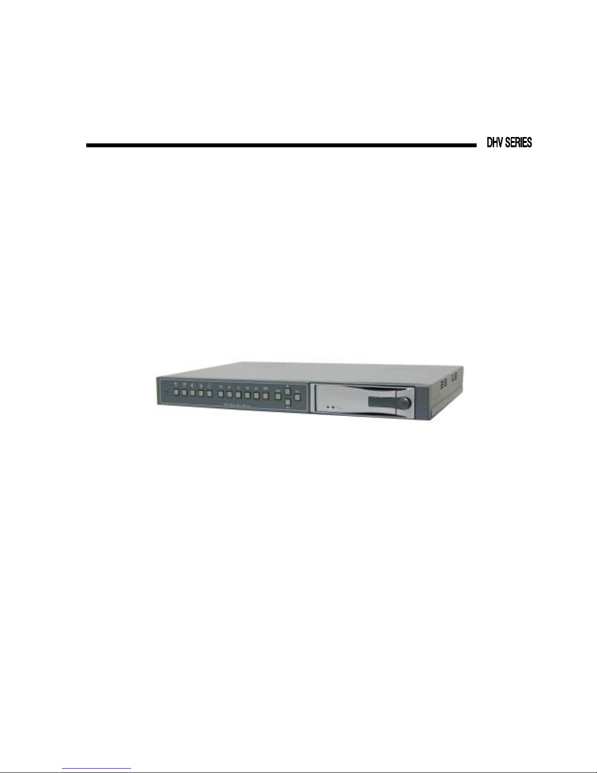
MAJOR OPERATING CONTROLS AND THEIR FUNCTIONS
1> Front View
(a) (b) (c) (d)(e) (f) (g) (h) (i) (j) (k) (l) (n) (p) (o) (m) (q)
(a) Power Indicator
(b) Display Channel 1 in full screen format
(c) Display Channel 2 in full screen format
(d) Display Channel 3 in full screen format
(e) Display Channel 4 in full screen format
(f) Display 4 channels in quad screen format
(g) Start recording
(h) Playback
(i) Pause
(j) Rewind
(k) Fast forward (FF x2, FF x4, FF x8)
(l) Stop recording or Playing back
(m)MENU Enter / exit the menu
(n) SELECT Select and Adjust
(o) Move the > cursor up or left
REC
Page 6
5
Version 1.2
(p) Move the > cursor down or right
(q) HDD cartridge
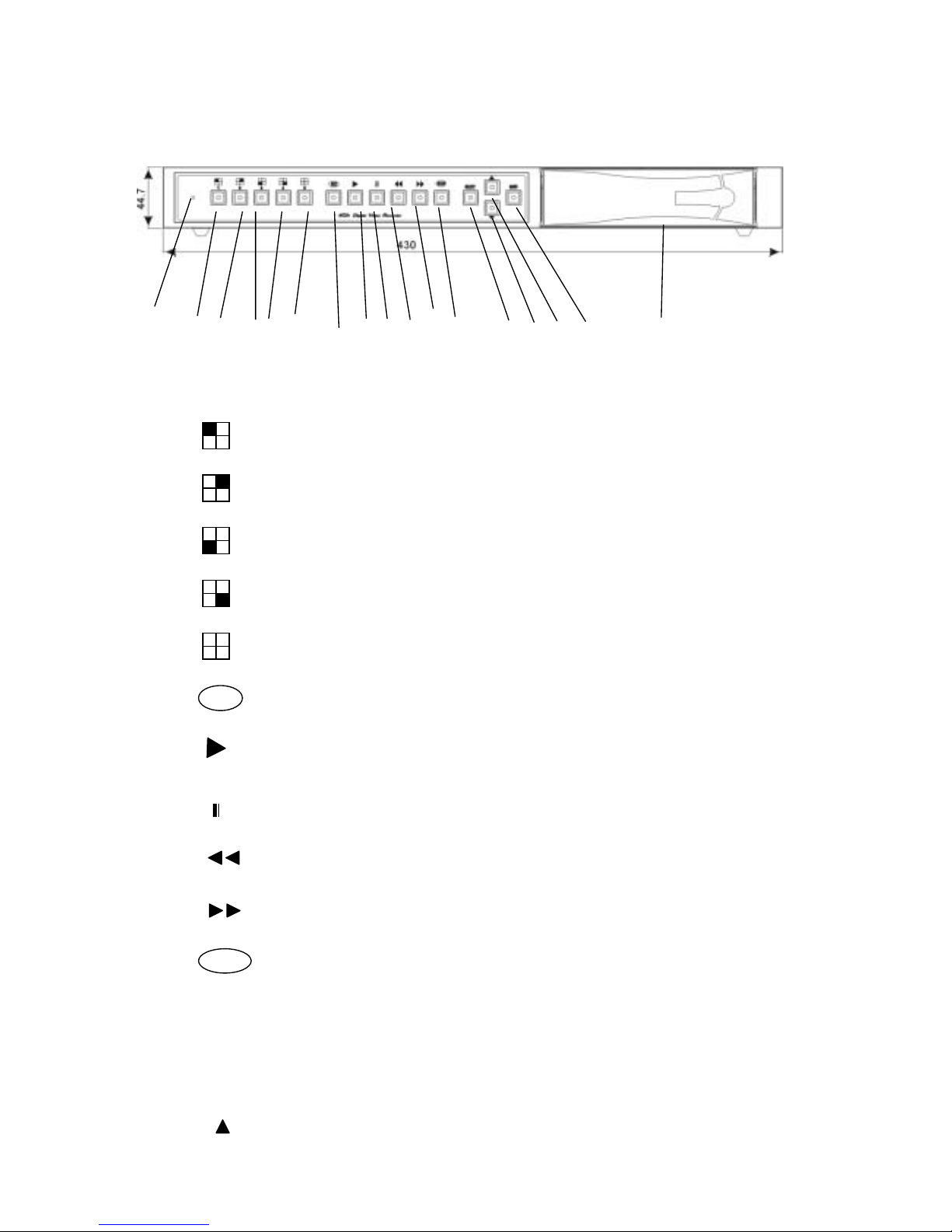
2> Rear View
(a) (b) (l) (c) (d) (e) (f) (g) (h) ( i ) ( j ) (k)
(m)
(a) IDE Plug - The connection port for the external HDD
(Slave HDD)
(b) IDE Power - The power for the external HDD (Slave HDD)
(c) Y/C Output
(d) Video Signal output 1 (1Vp-p/75Ω)
(e) Video Signal output 2 (1Vp-p/75Ω)
(f) Video Signal Input – Channel 1 ~ 4
(g) Video Signal Loop – Channel 1 ~ 4
(h) Sensor Input x 4, (NO, NC or Not Installed)
(i) Alarm Output x 1 (Relay out, NO switches to Alarm Close)
(j) Power Input (90~260Vac switching power)
(k) Power ON/OFF switch
(l) Cooling Fan
(m)Power Input (12Vdc)
Page 7
6
Version 1.2
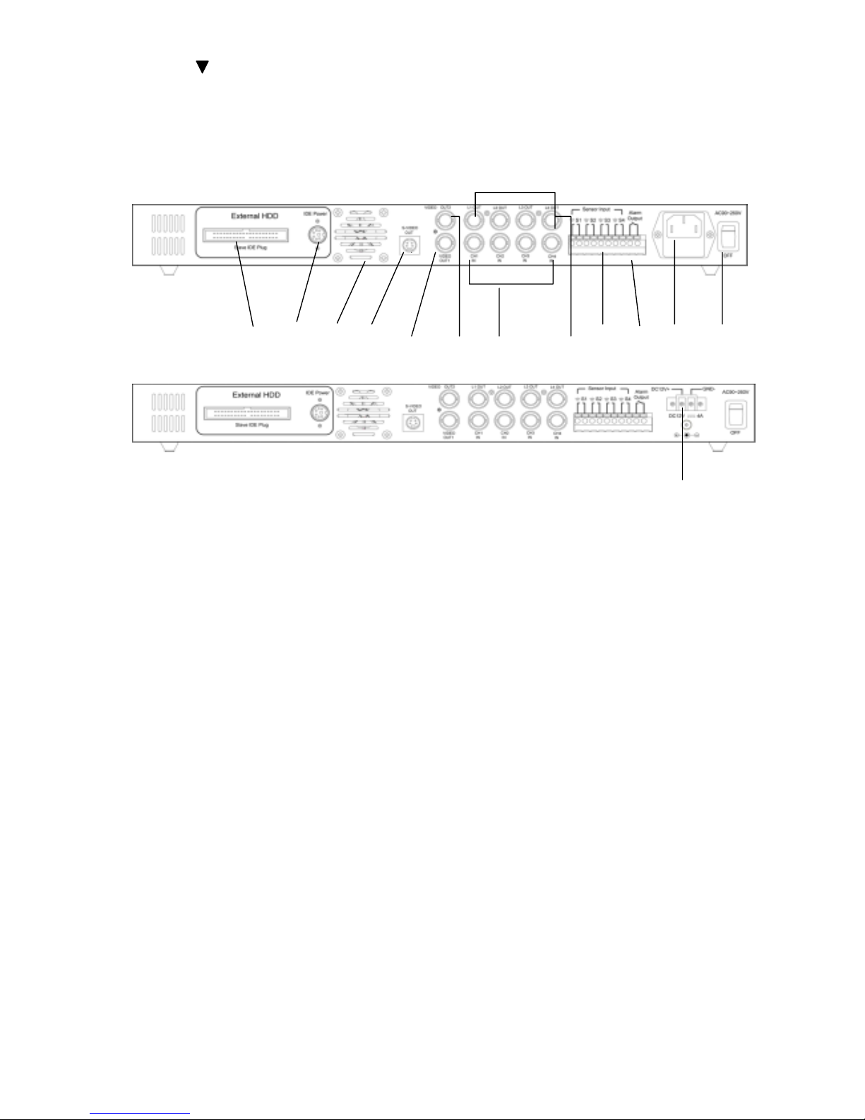
3> Bottom View ( NTSC / PAL System SELECT )
To change NTSC / PAL System SELECT Switch
Page 8

7
Version 1.2
MENU AND SYSTEM SETUP
There are two pages in setup menu.
■ To enter the MENU 1, press the MENU button on the front panel.
■ To enter MENU 2, select the NEXT PAGE and press the SELECT button.
■ To exit the setup menus, press the MENU button.
A cursor can be moved using the the ▲ or ▼ button on the front panel and press the
SELECT button to choose.
MENU 1 MENU 2
> DISPLAY CAMERA SELECT 1 2 3 4 > PASSWORD SETUP
RECORD CAMERA SELECT 1 2 3 4 TIME SETUP
RECORD MODE SELECT DUAL LANGUAGE SELECT
ENG/中
RECORD FIELD RATE 60 KEY TONE ON/OFF
RECORD VIDEO QUALITY HIGH SENSOR ALARM BEEP OFF/ON
RECORD SCHEDULE HDD FULL BEEP OFF/ON
SENSOR SETUP RECORD MESSAGE DISPLAY ON/OFF
MOTION DET SETUP
HARD DRIVE SETUP
NEXT PAGE (MENU 2)
1> MENU 1
1.1> DISPLAY CAMERA SELECT
To select cameras to be displayed on monitor.
■All options can be completed in rotation by pressing the SELECT button.
■User can also press the following buttons to select cameas to display or not
display.
1.2> RECORD CAMERA SELECT
To select cameras to be recorded.
■All options can be completed in rotation by pressing the SELECT button.
■User can also press the following buttons to select cameas to record or not record.
Page 9

8
Version 1.2
1.3> RECORD MODE SELECT
The recorder provides two recording modes.
1.3.1> The DUAL mode
In live monitoring or playing back, user can view full screen images of a
specific camera or the images of all seclected cameras in quad format.
1.3.2> The QUAD mode
User can view live quad format images and play back the quad format images
in real-time speed.
1.4> RECORD FIELD RATE
The record field rate means how many pictures to be recorded per second. There
are nine recording rate options to select - 60(50) fields /sec, 30 fields/sec, 20
fields/sec, 14 fields/sec, 10 fields/sec, 8 fields/sec, 6 fields/sec, 4 fields/sec and 2
fields/sec.
The system field rate
Recording Rate per camera= ----------------------------------------------------------------
The number of cameras
1.5> RECORD VIDEO QUALITY
Select video quality. There are three quality levels selectable - HIGH, NORMAL and
LOW.
1.6> RECORD SCHEDULE
Enter RECORD SCHEDULE menu, a time schedule table shows up. The 24
segments in the table represent 24 hours (one day). Tap the ▲ and ▼ buttons to
move the V cursor and press the SELECT button to set recording mode for each
hour.
V
+ S S S S A A A A A A A A A A A A A A S +
0 3 6 9 12 15 18 21 24
The three recording modes:
■ The symbol A means the CONTINOUS RECORDING mode. The recorder
records continuosly.
■ The symbol S means the SENSOR ALARM mode or MOTION DETECTION
mode. The recorder starts recording while activated by any sensor connected
to the recorder or by the detecting of motion.
■ The symbol means the NO RECORDING mode.
*Note: After press the button, the recorder will be controlled by the
record schedule.
RE
C
Page 10

9
Version 1.2
1.7> SENSOR SETUP
To enter the SENSOR SETUP menu, press the SELECT button, a sub menu display
as follows,
SENSOR SETUP
> POST-ALARM RECORD TIME 30
ALARM DURATION 20
CHANNEL-1 TYPE: NORMAL-OPEN
CHANNEL-2 TYPE: NORMAL-CLOSE
CHANNEL-3 NOT INSTALLED
CHANNEL-4 TYPE: NORMAL-OPEN
1.7.1> POST-ALARM RECORD TIME
When sensors or motion detection are activated, they will trigger the recorder
to record. As the activated sensors stop, the recording activity will remain a
period of time, which can be adjusted by pressing the SELECT button. The
options may be 5 sec、10 sec、15 sec、 20 sec、25 sec and 30 sec.
1.7.2> ALARM DURATION
When any sensor connected to the recorder or motion detection is activated,
the recorder will react an alarm to start the buzzer and relay. The buzzing
time may be OFF、5 sec、10 sec、15 sec、 20 sec、25 sec、30 sec and CONT
(continuous buzzing).
*Note: If under CONT (continuous) mode, press any button on the front panel
to clear buzzer and relay out.
1.7.3> SENSOR TYPE SETTINGS
The NORMAL OPEN, NORMAL CLOSE or NOT INSTALLED can be set up
for each channel.
Page 11

10
Version 1.2
1.8> MOTION DETECTION SETUP
MOTION DET SETUP
> MOTION DET CAMERA SELECT 1 2 3 4
MOTION DET CAMERA SENSITIVITY LOW
VIDEO LOSS CAMERA SELECT 1 2 3 4
VIDEO LOSS ALARM ON
1.8.1> MOTION DET CAMERA SELECT
To select cameras to enter or exit motion detection mode.
■All options can be completed in rotation by pressing the SELECT button.
■User can also press the following buttons to complete the selection.
1.8.2> MOTION DET SENSITIVITY
Select the sensitivities of motion detection. There are three sensitivity levels
selectable - HIGH, NORMAL and LOW.
1.8.3> VIDEO LOSS CAMERA SELECT
To select cameras to enter or exit Video Loss Detection Mode.
■All options can be completed in rotation by pressing the SELECT button.
■User can also press the following buttons to complete the selection.
1.8.4> VIDEO LOSS ALARM
ON: Under Video Loss Alarm mode, the DVR beeps when one or all of the 4
Channels lose the video signal.
OFF: No beeping.
Page 12

11
Version 1.2
1.9> HARD DRIVE SETUP
To enter the HARD DRIVE SETUP menu, press the SELECT button. A sub menu
shows as follows,
HARD DRIVE SETUP
> OVERWRITE ENABLED YES
MASTER HDD SIZE 76319 MB
MASTER HDD USED 1968 MB 2 %
MASTER HDD FORMAT
SLAVE HDD SIZE 76319 MB
SLAVE HDD USED 0 MB 0%
SLAVE HDD FORMAT
This menu displays hard disk drive capacities, used capacities and percentages. It
also allows user to
■ Format hard disk drive
■ Setup hard disk drive overwrites.
1. 9.1> OVERWRITE ENABLED
YES: If HDD is full, the recording continues, the recorder will eventually go
into OVERWRITE mode, which means that the most dated data will
be replaced with the new data.
NO: If HDD is full, the recorder will stop recording.
1. 9.2> HDD FORMAT
To format the equipped HDD, user needs to enter password to make HDD
formatted automatically. Factory default HDD format password is “55555”.
*Note: To change password, please refer to 2.1 PASSWORD SETUP on
page 10.
1.10> ENTER MENU 2
MENU 1
> NEXT PAGE (MENU 2)
Pressing the SELECT button to enter MENU 2.
Page 13

12
Version 1.2
2> MENU 2
Select NEXT PAGE in MENE 1 and press the SELECT button to enter MENU2.
MENU 2
> PASSWORD SETUP
TIME SETUP
LANGUAGE SELECT
ENG/中
2.1> PASSWORD SETUP
Pressing the SELECT button to enter the sub menu is as follows.
CURRENT PASSWORD _ _ _ _ _ _
NEW PASSWORD _ _ _ _ _ _
PASSWORD CONFIRM _ _ _ _ _ _
Press the above buttons on the front panel to enter the current password, new
password and then enter the new password again to confirm. The buttons
represent the numbers above them.
Note: The factory default password is “55555”.
2.2> TIME SETUP
To enter the TIME SET menu as follows. Pressing the ▲ or ▼ button to move the
cursor and tapping the SELECT button to adjust date and time.
TIME
2003/02/24 10:23:45
2.3> LANGUAGE SELECT
The recorder provides the on screen menus in English and in Chinese. Press the
SELECT button to choose.
2.4> KEY TONE
ON: The DVR beeps as pushing the buttons.
OFF: No beeping.
Page 14

13
Version 1.2
2.5> SENSOR ALARM BEEP
ON: Under sensor alarm mode, the DVR beeps when it is activated to record.
OFF: No beeping.
2.6> HDD FULL BEEP
ON: The DVR will beep when the running HDD is 99% full. The beeping continues
unless the HDD is full.
OFF: No beeping.
2.7> RECORD MESSAGE DISPLAY
ON: The related messages are displayed on the screen.
OFF: Not being displayed.
3> SENSOR ALARM CONNECTION
The recorder has 4 sensor input terminals on the rear panel. In the sensor alarm mode
any sensor is activated, the recorder will start to record the images from the
corresponding channel. The correspondence chart is as follows.
4> HARD DISK DRIVE INSTALLATION
4.1> Front Panel Description
1. HDD Access indicators
2. Power indicator
3. Active-handle
4. Handle
5. Cartridge frame
6. Key lock
4.2> Power Indicator and HDD Access indicator
When power is turned on, the indicator will display the following:
Item Indicator
Power Indicator Green LED
HDD Access Indicator
Amber LED
Sensor Corresponding Channel
S1 Channel 1
S2 Channel 2
S3 Channel 3
S4 Channel 4
Page 15

14
Version 1.2
4.3> Key lock
Status
Segment
Power status Security status
A ON Locked (Non-removable)
B OFF Locked (Non-removable)
C OFF Unlocked (Removable)
4.4> Installing Hard Drive into Cartridge
Step 1
1-1 . Pull the active-handle outwards and use the miniature key provided and
insert into the keyhole, turning the key anti-clockwise, then the handle will
auto-eject for pulling out. (Fig.1)
1-2. Pull the handle outwards to remove the carrier body away from the cartridge
frame.
(Fig.2)
Step 2
2-1. Push the release latch to slide the top cover backwards and remove. (Fig.3)
Step 3
3-1. Insert the DC power cable and IDE cable on the HDD. (Fig.4)
3-2. Position the HDD into carrier body and secure the HDD using the four 6#-32
screws provided. (Fig.5)
A
B
C
Fig. 1 Fig. 2
Fig. 3
Fig. 5 Fig. 4
Page 16

15
Version 1.2
Step 4
4-1. Slide the top cover back to the carrier body by sliding forward to secure. (Fig.6)
Step 5
5-1. Slide the carrier body into the recorder and push carrier body further into
cartridge frame until fully inserted. (Fig.7 and Fig.8)
5> CONNECTING EXTERNAL HARD DISK DRIVE
For installing hard disk drive, please connect recorder and external hard disk drive case
with a power cord and a flat wire, which come with hard disk drive case. Refer to the
following pictures.
*Note: To turn the recorder off before install.
Fig. 6
Fig. 8
Fig. 7
Power Cord
Hard Disk Drive Case
40 Pin IDE Flat Cable
Page 17

16
Version 1.2
6> MASTER/SLAVE HARD DISK DRIVE CONFIGURATION
■ The swappable hard disk drive installed in the recorder should be set as master drive.
■ When the external hard disk drive is installed, it should be set as slave drive.
*Note: To install external hard disk drive, please turn the recorder off to allow the
recorder to detect new hard disk drive when turn the recorder on again.
For master/slave configuration, please refer to instruction gui de of HDD manufacturers.
An example as follows,
(7-8)(5-6)(3-4)(1-2)
Limited capacity to 32 Gbytes
Master or single drive
Drive is a slave
Master with a non-ATAcompatible slave
Enable cable select
Slave HDD
Master HDD
Power Input
40
p
in Flat Cable Connecto
r
Pins for master/slave settings
Refer to this chart and set the jumpers
Instruction Guide
Setting slave HDD
Setting master HDD
Page 18

17
Version 1.2
7> SECURITY LOCK
DVR allows security lock function for button on the front panel.
Press five time "||" button into security lock mode. At once under security lock mode,
monitor will display on right-upper corner of screen. Press five time "||" button
again to disable security lock mode. Meanwhile bol will disappear on screen.
■
RECORDING AND PLAYBACK
1.> RECORDING
Press the button in the front panel to start recording. Push the button
to stop recording. While in the recordering mode, some symbols display on the monitor
screen as follows,
symbol
sym
RE
C
STOP
DUAL REC [M] (A) 2003/05/13 12:00:00
﹝R﹞CH1
﹝R﹞CH3
CH2﹝R﹞
CH4﹝R﹞
QUAD REC [S] (S) 2003/05/13 12:00:00
CH1
CH3
CH2
CH4
1
6 %
24% [OVWR]
PAUSE
Page 19

18
Version 1.2
1.1>DUAL REC / QUAD REC
■ DUAL REC: In live monitoring or playing back, user can view full screen images
of a specific camera or the images of all seclected cameras in quad format.
DHV-410M Recording Time Table NTSC (DUAL)
fields per second/system 60 30 20 8 4
fields per second/channel 15 7.5 5.0 2.0 1.0
Hours / 80GB
High 35 70 104 207 521
Normal 49 98 147 369 737
Low 57 114 170 426 852
Hours / 120GB
High 52 104 157 392 783
Normal 74 147 221 552 1105
Low 85 170 256 639 1278
Hours / 160GB (2 x 80GB HDD)
High 70 139 209 521 1043
Normal 98 197 295 737 1474
Low 114 227 341 852 1703
Hours / 240GB ( 2 x 120GB HDD)
High 104 209 313 782 1564
Normal 147 295 442 1106 2211
Low 170 341 511 1277 2555
Remark: Recording time are variety according to some image factors (e.g. static or moving picture, day or night picture)
DHV-410M Recording Time Table PAL (DUAL)
fields per second/system 50 25 16 8 4
fields per second/channel 12.5 6.25 4.0 2.0 1.0
Hours / 80GB
High 42 84 125 313 626
Normal 59 118 177 442 884
Low 68 136 204 511 1022
Hours / 120GB
High 63 125 188 470 940
Normal 88 177 265 663 1327
Low 102 204 307 767 1534
Hours / 160GB (2 x 80GB HDD)
High 83 167 250 626 1251
Normal 118 236 354 885 1769
Low 136 273 409 1022 2045
Hours / 240GB ( 2 x 120GB HDD)
High 125 250 375 939 1877
Normal 177 354 531 1327 2653
Low 204 409 613 1533 3065
Remark: Recording time are variety according to some image factors (e.g. static or moving picture, day or night picture)
Page 20

19
Version 1.2
■
QUAD REC: User can view live quad format images and play back the quad
format images in real-time speed.
DHV-410M Recording Time Table NTSC (QUAD)
fields per second/system 60 30 20 8 4
Hours / 80GB
High 19 37 56 140 280
Normal 27 54 81 202 404
Low 33 67 100 251 502
Hours / 120GB
High 28 56 84 210 420
Normal 41 83 124 311 621
Low 50 100 151 377 753
Hours / 160GB (2 x 80GB HDD)
High 37 75 112 280 560
Normal 54 108 162 404 808
Low 67 134 201 502 1004
Hours / 240GB ( 2 x 120GB HDD)
High 56 112 168 420 840
Normal 81 162 242 606 1212
Low 100 201 301 753 1506
Remark: Recording time are variety according to some image factors (e.g. static or moving picture, day or night picture)
DHV-410M Recording Time Table PAL (QUAD)
fields per second/system 60 30 20 8 4
Hours / 80GB
High 22 45 67 168 337
Normal 32 65 97 242 484
Low 40 80 121 302 603
Hours / 120GB
High 34 67 101 252 504
Normal 50 99 149 373 745
Low 60 120 181 452 904
Hours / 160GB (2 x 80GB HDD)
High 45 90 134 336 671
Normal 65 129 194 485 970
Low 80 161 241 602 1204
Hours / 240GB ( 2 x 120GB HDD)
High 67 134 202 504 1008
Normal 97 194 291 727 1454
Low 120 241 361 904 1807
Remark: Recording time are variety according to some image factors (e.g. static or moving picture, day or night picture)
Page 21

20
Version 1.2
1.2>[M] / [S]
■ [M] : Images are recorded to mater hard disk drive.
■ [S] : Images are recorder to slave hard disk drive.
1.3> (A) / (S) / (-)
■ (A) : The recorder records continuously.
■ (S) : The recorder reacts to start recording while activated by any sensor
connected tothe recorder.
■ (-) : No recording.
1.4>[R]
The symbol [R] means that the recorder is recording. It also indicates which
channel is recorded.
1.5> 16%
This symbol indicates the percentage of the running HDD capacity storing images.
16% 84%
The whole capacity of the HDD
Ima
g
e Data No Data
1.6> 24% [OVWR]
This symbol means that the recorder is in OVERWRITE mode. At the 24 % of the
HDD capacity is saved with new data.
24% 76%
The whole capacity of the HDD
New Data Earlier Data
Page 22

21
Version 1.2
2. > PLAYBACK
To play back, Press the button to enter playback menu.
SEARCH TIME
HARD DRIVE: MASTER
03/04/27 08:05:34 -- 03/05/12 18:27:09
--------- RECORD LIST ---------
01 CONT 2003 / 05 / 12 07: 43: 12
02 SENSOR 2003 / 05 / 12 02: 23: 54
03 SENSOR 2003 / 05 / 12 01: 44: 35
04 CONT 2003 / 05 / 11 10: 17: 22
:
Step 1: Select hard disk drive to play back.
Step 2: Go to the dates and times shown under hard drive option. Press the ▲ or
▼ button to move the cursor and press the SELECT button to set the
date and time starting to play back.
OR
Press the button to enter RECORD LIST, select a record and Press
the button to play back.
To exit the RECORD LIST, Press the button.
Button: Press this button to freeze picture when play back.
Button: Press this button to fast forward, and press button again to adjust
speed at 2 / 4 / 8 times.
Button: Press this button to fast rewind.
 Loading...