

Page 1
Instruction Manual
E
E
D
D
R
R11664400//11662200//992200
Page 2

EVERF O C U S E L E C T R O N ICS CO RP O R A T I O N
EDR1640 / 1620 / 920
Instruction Guide
2005 EverFocus Electronics Corp
www.everfocus.com
All rights reserved. No part of the contents of this manual may be reproduced or transmitted in any form or by any
means without written permission of the Everfocus Electronics Corporation.
Release Date: August 2008
QuickTime is a registered trademark of the Apple Computer, Inc.
Windows isa registered trademark of the Microsoft Corporation.
Linksys is a registered trademark of the Linksys Corporation.
D-Link is a registered trademark of the D-Link Corporation.
DynDNS is a registered trademark of the DynDNS.org Corporation.
Other product and company names mentioned herein may be the trademarks of their respective owners.
Page 3

ii
Federal Communication Commission Interference Statement
This equipment has been tested and found to comply with the limits for a Class B digital device,
pursuant to Part 15 of the FCC Rules. These limits are designed to provide reasonable protection
against harmful interference in a residential installation. This equipment generates, uses and can
radiate radio frequency energy and, if not installed and used in accordance with the instructions,
may cause harmful interference to radio communications. However, there is no guarantee that
interference will not occur in a particular installation. If this equipment does cause harmful
interference to radio or television reception, which can be determined by turning the equipment
off and on, the user is encouraged to try to correct the interference by one of the following
measures :
• Reorient or relocate the receiving antenna.
• Increase the separation between the equipment andreceiver.
• Connect the equipment into an outlet on a circuit different from that to which the receiver is
connected.
• Consult the dealer or an experienced radio/TV technician for help. FCC Caution: Any changes
or modifications not expressly approvedby the party responsible for compliance could void the
users’s authority to operate this equipment. This device complies with Part 15 of the FCC Rules.
Operation is subject to the following two conditions: (1) This device may not cause harmful
interference, and (2) this device must accept any interference received, including interference
that may cause undesired operation.
This device and its antenna(s) must not be co-located or operating in conjunction with any other
antenna or transmitter.
Page 4

iii
Non-LPS or TNV output connectors identify the type of circuit, intended cable
type or relevant circuit characteristics. (Marking or Instruction)
“ CATUION: Risk of Explosion if Battery is replaced by an Incorrect Type.
Dispose of Used Batteries According to the Instructions.”
Page 5

iv
TABLE OF CONTENTS
1. PRODUCT OVERVIEW..................................................................................................1
1.1 FEATURES...........................................................................................................................1
1.2 SPECIFICATIONS..................................................................................................................2
1.3 FRONT PANEL KEYPADS.....................................................................................................4
1.4 BACK PANEL CONNECTIONS...............................................................................................7
1.5 MONITOR DISPLAY...........................................................................................................10
2. INSTALLATION.............................................................................................................13
2.1 VIDEO CONNECTIONS, DVR CASCADING..........................................................................14
2.2 AUDIO CONNECTION INSTALLATION ................................................................................ 16
2.3 SPEED DOME INSTALLATION ............................................................................................17
2.4 ALARM INPUT / OUTPUT INSTALLATION...........................................................................18
2.5 EDA800S INSTALLATION (OPTIONAL)..............................................................................21
2.6 NETWORK CONNECTION................................................................................................... 21
2.6.1. Direct PC connection through crossover network cable..................................................................... 21
2.6.2. Network connection through patch cable............................................................................................ 22
2.6.3. Network system requirements............................................................................................................... 22
2.7 HARD DISK DRIVE INSTALLATION....................................................................................22
2.8 FINAL INSTALL PROCESS .................................................................................................. 23
3. DVR MENU SETUP........................................................................................................... 24
3.1 TIME/DATE SETUP MENU................................................................................................. 25
3.2 CAMERA SETUP MENU .....................................................................................................29
3.3 RECORD SETUP MENU ...................................................................................................... 33
3.4 ALARM SETUP MENU .......................................................................................................35
3.5 MOTION SETUP MENU ...................................................................................................... 38
3.6 VIDEOLOSSSETUP MENU ............................................................................................. 41
3.7 NETWORK SETUP MENU................................................................................................... 43
3.7.1 CONFIG............................................................................................................................................... 43
3.7.2 ALARM (NETWORK)........................................................................................................................... 45
3.7.3 EMAIL.................................................................................................................................................. 46
3.7.4 PASSWORD.......................................................................................................................................... 47
3.7.5 PPPOE ................................................................................................................................................. 48
3.7.6 DDNS ................................................................................................................................................... 49
3.8 SCHEDULE SETUP MENU ..................................................................................................51
3.9 DISK SETUP MENU ...........................................................................................................53
3.10 CONTROL SETUP MENU ................................................................................................. 55
3.11 WARNING SETUP MENU.................................................................................................57
3.11.1 FAN FAULT ......................................................................................................................................... 57
3.11.2 HDD TEMP.......................................................................................................................................... 58
3.11.3 NO HDD............................................................................................................................................... 60
Page 6

v
3.11.4 HDD FULL........................................................................................................................................... 61
3.12 SYSTEM SETUP MENU.................................................................................................... 63
4. RECORDING OVERVIEW..............................................................................................66
4.1 INSTANT (N) RECORDING SETUP ......................................................................................66
4.2 SCHEDULE RECORDING SETUP .........................................................................................67
4.3 EVENT RECORDING SETUP................................................................................................67
4.4 ALARM INPUT RECORDING (INPUT TRIGGER) ..........................................................69
5. PLAYBACK OVERVIEW................................................................................................70
5.1 BASIC PLAYBACK.............................................................................................................70
5.2 SEARCH PLAYBACK..........................................................................................................71
6. COPYING VIDEO.............................................................................................................. 75
6.1 VIEWING A COPIED FILE........................................................................................................77
7. CALL OVERVIEW............................................................................................................ 78
8. SCREEN DISPLAY SETTING & MODE.......................................................................80
8.1 MODE BUTTON.................................................................................................................82
9. FIRMWARE UPGRADE...................................................................................................83
10. NETWORKING OVERVIEW.......................................................................................84
10.1 INTRODUCTION TO TCP/IP ............................................................................................ 84
10.2 SUBNET MASKS ............................................................................................................. 84
10.3 GATEWAY ADDRESS ...................................................................................................... 84
10.4 VIRTUAL PORTS.............................................................................................................85
10.5 PRE-INSTALLATION........................................................................................................85
10.6 WHAT TYPE OF NETWORK CONNECTION DO YOU HAVE?............................................... 87
10.7 SIMPLE ONE TO ONE CONNECTION ................................................................................ 87
10.8 DIRECT HIGH SPEED MODEM CONNECTION..................................................................96
10.9 ROUTER OR LAN CONNECTION ..................................................................................... 98
11. LINKSYS PORT FORWARDING ..............................................................................101
12. D-LINK PORT FORWARDING..................................................................................105
13. EVERFOCUS DDNS SETUP .......................................................................................108
14. VIEWING THROUGH INTERNET EXPLORER.................................................... 110
14.1 SEARCH........................................................................................................................119
14.1.1 Search by TIME....................................................................................................................................... 119
14.1.2 Search by EVENT.................................................................................................................................... 120
14.2 PTZ CONTROL.............................................................................................................. 121
14.3 REMOTE ARCHIVE .......................................................................................................122
14.4 REMOTE CONFIGURATION............................................................................................126
15. INTERFACE SPECIFICATIONS..............................................................................133
Page 7

vi
15.1 TRANSMISSION SETTING ..............................................................................................133
15.2 REMOTE CONTROL PROTOCOL..................................................................................... 134
APPENDIX A: REMOTE CONTROL...................................................................................139
APPENDIX B: MOUSE INSTALLATION ...........................................................................140
APPENDIX C: ALARM BOARD CONFIGURATION....................................................... 143
APPENDIX D: LAPSE MODE RECORDING TABLE.......................................................144
TROUBLESHOOTING...........................................................................................................151
Page 8

vii
Safety Warning
Notice:
The information in this manual was current when published.
The manufacturer reserves the right to revise and improve its products.
All specifications are therefore subject to change without notice.
WARNING
TO REDUCE RISK OF FIRE OR ELECTRIC SHOCK,
DO NOT EXPOSE THIS APPLIANCE TO RAIN OR MOISTURE.
Note:
This is a class A product. In a domestic environment this product
may cause radio interference, in which case the user may be
required to take adequate measures.
Page 9

viii
Safety Precautions (1)
Refer all work related to the installation of this product to qualified service personnel or
system installers.
Do not block the ventilation opening or slots on the cover.
Do not drop metallic parts through slots. This could permanently damage the appliance. If
this does happen, turn the power off immediately and contact qualified service personnel for
service.
Do not attempt to disassemble the appliance. There are no user-serviceable parts inside. To
prevent electric shock, do not remove screws or covers. If service is required, contact
qualified service personnel for maintenance. Handle the appliance with care. Do not strike or
shake, as this may damage the appliance.
Do not expose the appliance to water or moisture, nor try to operate it in wet areas. Take
immediate action if the appliance becomes wet. If this does happen, turn the power off and
refer servicing to qualified service personnel. Moisture may damage the appliance and also
cause electric shock.
Do not use strong or abrasive detergents when cleaning the appliance body. Use a dry cloth
to clean the appliance when it is dirty. When the dirt is hard to remove, use a mild detergent
and wipe gently.
Do not overload outlets and extension cords as this may result in a risk of fire or electric
shock.
Do not operate the appliance beyond its specified temperature, humidity or power source
ratings. Do not use the appliance in an extreme environment where high temperature or high
humidity exists. Use the appliance at temperature within indoor type DVR for 32oF ~ 104oF
and a humidity below 90%. The input power source for this appliance is AC100~240V.
Page 10

ix
Safety Precautions (2)
Read Instructions — All the safety and operating instructions should be read before the unit is
operated.
Retain Instructions — The safety and operating instructions should be retained for future
reference.
Warnings — All warnings on the unit and in the operating instructions should be adhered to.
Follow Instructions — All operating and user instructions should be followed.
Cleaning — Unplug the unit from the outlet before cleaning. Do not use liquid cleaners or
aerosol cleaners. Use a damp cloth for cleaning
Water and Moisture — Do not use this unit near water-for example, near a bath tub, wash
bowl, kitchen sink, or laundry tub, in a wet basement, near a swimming pool, in an unprotected
outdoor installation, or any area which is classified as a wet location.
Servicing — Do not attempt to service this unit by yourself as opening or removing covers may
expose you to dangerous voltage or other hazards. Refer all servicing to qualified service
personnel.
Power Cord Protection — Power supply cords should be routed so that they are not likely to be
walked on or pinched by items placed upon or against them, playing particular attention to cords
and plugs, convenience receptacles, and the point where they exit from the appliance.
Object and Liquid Entry — Never push objects of any kind into this unit through openings as
they may touch dangerous voltage points or short-out parts that could result in a fire or electric
shock. Never spill liquid of any kind on the unit.
Page 11

1
1. Product Overview
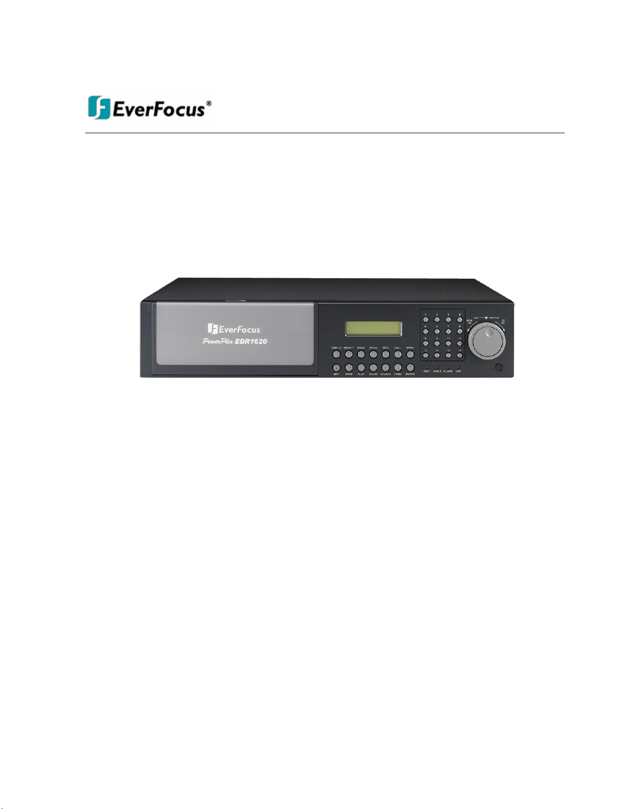
The EDR1640/1620/920 DVR’s are the industry’s first full-featured digital video recorder designed
specifically for use within the CCTV security industry. EDR1640/1620/920 DVR’s incorporates all
the benefits of digital video recording, is simple to install, and operates just like a VCR. Highly
efficient compression technology and superior resolution of recorded images make the Digital Video
Recorder stand out from the competition as the best choice for security surveillance.
1.1 Features
Multiplex Operation (Recording, Playback, Archiving, Remote Viewing)
Built-in MPEG4 Codec with Configurable Quality
Embedded Linux OS
Variable Recording Speeds Up to 480 (EDR1640)/240 (EDR1620, 920)images per second
4-channel Audio Recording Capabilities (local)
Motion Detection Capabilities
Two 3.5” Hot-Swap Hard Disks, expendable to max. 50 Hard Disks with EDA800S
(optional)
SCSI Interface for External Expanded Storage
Ethernet Interface for Remote Network Viewing and Controlling
RS232/RS485 for Remote Control
Shuttle/Jog Dial for Picture-by-Picture or Fast/Slow Viewing
Easy-to-use User Friendly Control via front panel keypad, Shuttle/Jog, Mouse and Control
Keyboard (optional)
On-Screen Menus Operations with Multi-Language Support
Real-Time Live Display for all Cameras
USB 2.0 Interface for Archiving
Support external USB DVD+RW forarchiving (optional)
Water Mark Capabilities
Remote configuration function
Remote Firmware Upgrade function
Motion detection function can be scheduled according to user’s setting
Chapter
1
Page 12

2
1.2 Specifications
Video Format
NTSC or PAL
Video Input
16 / 9 BNC camera inputs (1Vp-p/75ohm)
1 BNC video out (1Vp-p/75ohm) and S-Video out for Main
Monitor
1 BNC video out (1Vp-p/75ohm) for Call Monitor
Video Output
16 / 9 BNC video out (1Vp-p/75ohm) for Looping
Video Compression
MPEG4
EDR1640 Recording
Resolution
720x480 (NTSC:120IPS) / 720x576 (PAL:100IPS)
720x240 (NTSC:240IPS) / 720x288 (PAL:200IPS)
360x240 (NTSC:480IPS) / 360x288 (PAL:400IPS)
EDR1620 Recording
Resolution
720x480 (NTSC: 60 IPS) / 720x576 (PAL: 50IPS)
720x240 (NTSC:120IPS) / 720x288 (PAL:100IPS)
360x240 (NTSC:240IPS) / 360x288 (PAL: 200IPS)
EDR920 Recording
Resolution
720x480 (NTSC: 60 IPS) / 720x576 (PAL: 50IPS)
720x240 (NTSC:120IPS) / 720x288 (PAL:100IPS)
360x240 (NTSC:240IPS) / 360x288 (PAL: 200IPS)
Video Display
Full, PIP (Live only), 4, 7, 8/9, 10, 13, 16, and 2x2 Zoom for
Live and Playback
Video Pause
Yes
Alarm Inputs
16/9 Alarm Inputs
Alarm Outputs
4 Alarm Outputs
Hard Disk Storage
Two Hot-Swappable 3.5” IDE Hard Disk
Recording Rate
1640: Up to 480 IPS for NTSC (400 IPS forPAL)
1620/920: Up to 240 IPS for NTSC (200 IPS for PAL)
Recording Mode
Continuous, Schedule, Event (Motion and Alarm) recording
Playback Rate
Up to 60/50 Images per second for NTSC/PAL
Playback Search
By Date/Time or Event (Motion, Video Loss, Alarm)
Motion Detection
Yes, with configurable detection areas & sensitivity
Video Loss Detection
Yes
Event Log
Yes
Setup
Menu Driven On Screen Display setup
User Input Device
Front panel keypad with Shuttle/Jog Wheel, IR Remote Control,
PS/2 Mouse (optional), EKB500 (optional)
Timer
Built-in real time clock with time synchronization
through NTP Server
Watch Dog Timer
Yes
Title
12-character title for each camera
Ethernet
RJ45 connector for 10/100 Mbps network communication
Archive
USB 2.0 Interface Device for archiving
Page 13

3
RS-232
9-pin female connector for testing purposes
RS-485
For Keyboard and PTZ connection
Audio
4 mono inputs, 1 mono (SPEAKER) outputs
Power Source
AC100~240
Power Consumption
60W
Dimension
430 (W) x 88 (H) x 300 (D) mm / 17” (W) x 3.5” (H) x 12” (D)
Weight
6.24 kg (approx. 13.7 lbs)
Operating Temperature
0oC ~ +40oC / 32℉ ~104℉
Recording Rate
NTSC
PAL
1640 model
D1 720x480 : 120 IPS
Half D1 720x240 : 240 IPS
CIF 360x240 : 480 IPS
D1 720x576 : 100 IPS
Half D1 720x288 : 200 IPS
CIF 360x288 : 400 IPS
1620 model
D1 720x480 : 60 IPS
Half D1 720x240 : 120 IPS
CIF 360x240 : 240 IPS
D1 720x576 : 50 IPS
Half D1 720x288 : 100 IPS
CIF 360x288 : 200 IPS
920 model
D1 720x480 : 60 IPS
Half D1 720x240 : 120 IPS
CIF 360x240 : 240 IPS
D1 720x576 : 50 IPS
Half D1 720x288 : 100 IPS
CIF 360x288 : 200 IPS
Page 14
4
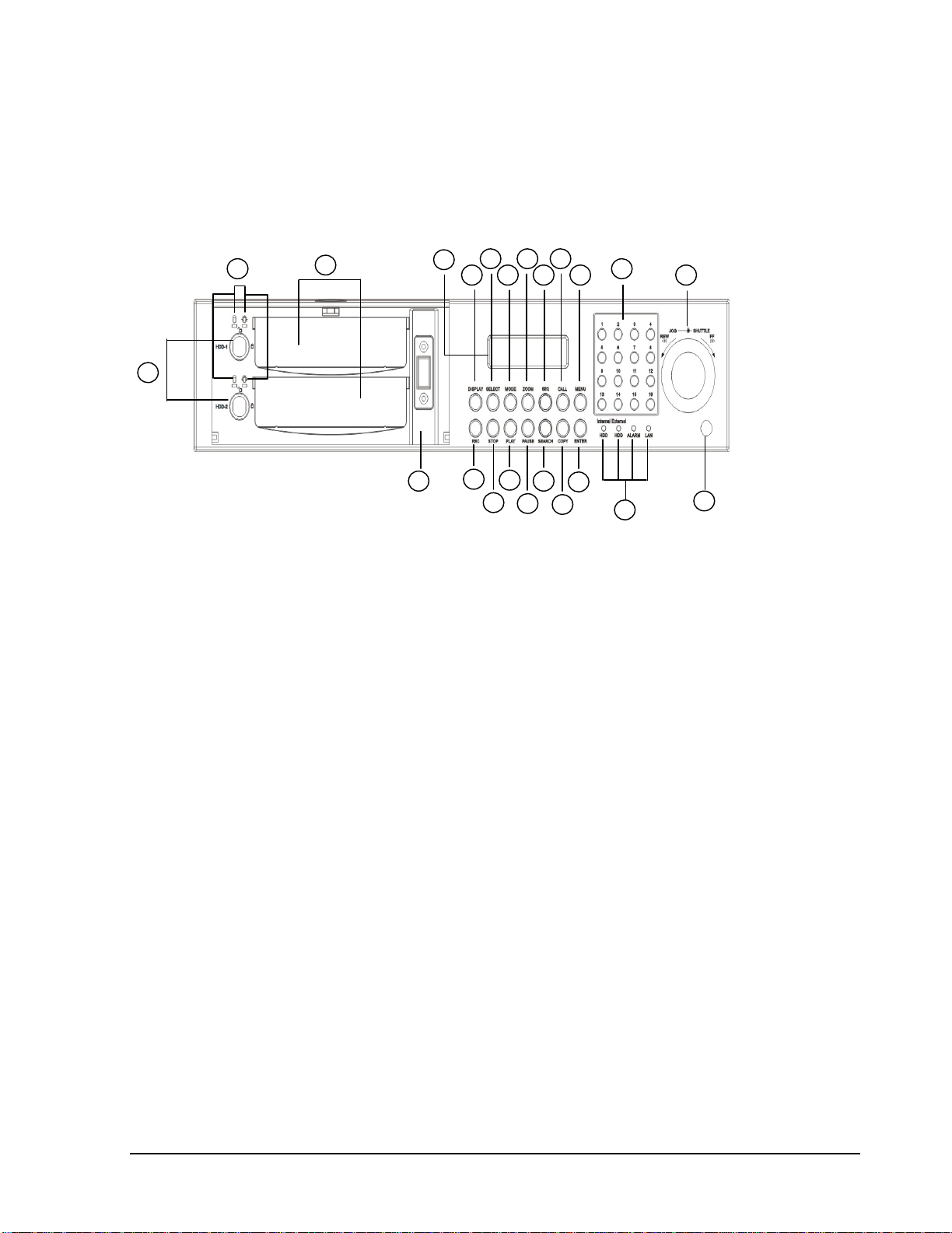
1.3 Front Panel Keypads
Keys:
15
1
2
3
4
5
6
7
89101112
13
14
16
17
18
19
20
21
22
23
1. REC: Press this key to start instant recording.
2. STOP: Press this key to stop recording and playing back.
3. PLAY: Press this key to start playing back.
4. PAUSE: Press this key to pause the playback picture.
5. SEARCH: Press this key to enter the SEARCH MENU.
7. ENTER: Press this key to enter items or jump to next subentry in the menu setting.
8. DISPLAY: Press this key to cycle through the display of channels and/or status bar.
6. COPY: Press this key to enter the Copy Menu.
Page 15
5
12. SEQ: Press this key to enter the auto sequential switching mode.
13. CALL: Press this key to enter and set upCALL MENU.
14. MENU: Press this key to enter/exit the Main Menu or to exit from any submenu.
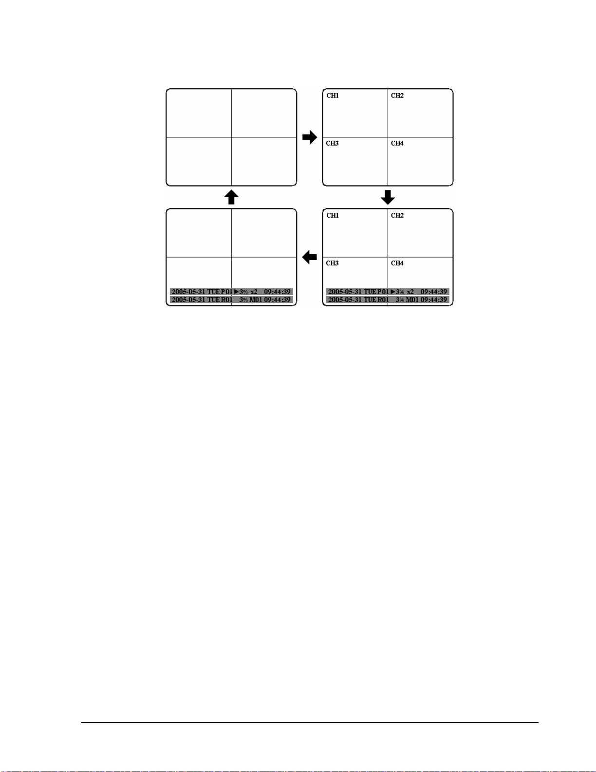
10. MODE: Switch PIP, 4, 7, 9, 10, 13 and 16 displays inLive and Playback
11. ZOOM: In full screen mode, 2x electronic zoom. Zoom screen can be moved through
JOG. ENTER key changes the scroll direction between horizontal and vertical. Pressing
the zoom key again switches the electronic zoom off.
In multiscreen mode: Image orientation adjustment. Use theJOG to adjust the image to
the monitor type. ENTER switches between horizontal and vertical adjustment. Press the
zoom key again to exit screen adjustment.
9. SELECT: On live view, press this key to assign a camera to a multi-screen or to adjust
single screen display properties. In menus, press this key to select certain features.
Page 16

6
15
. Shuttle and Jog Dial
Shuttle:
In the Playback mode, turn the Shuttle dial to fast forward/rewind
the video.
In the Pause mode, turn the Shuttle dial to slow forward/rewind
the video.
In the event list, turn the Shuttle to change pages.
Jog Dial:
In the Pause mode, turn the Jog dial to forward/rewind the video
frame by frame. In the Menu mode, turn the Jog dial to change
settings and values in subentries.
16
. System LEDs
LEDs for system active HDD, ALARM and LAN display.
17
. Channel Key (1~16)
Press channel key (CH1~CH16) to display that channel in full screen view.
18
. HDD LOCK
Turn on HDD power and prevent HDD theft.
19
. Hard Disk Tray
Hard Disk holder for HDD.
20
. HDD LED’s
LED’s for HDD active power (GREEN) and data reading/writing (RED).
21
. LCD Panel
To display Date and Time, and other system information.
22
. IR receiver
Receiver for optional infrared remote control.
23. USB slot
USB port allows you to archive video files to USB device.
Page 17
7
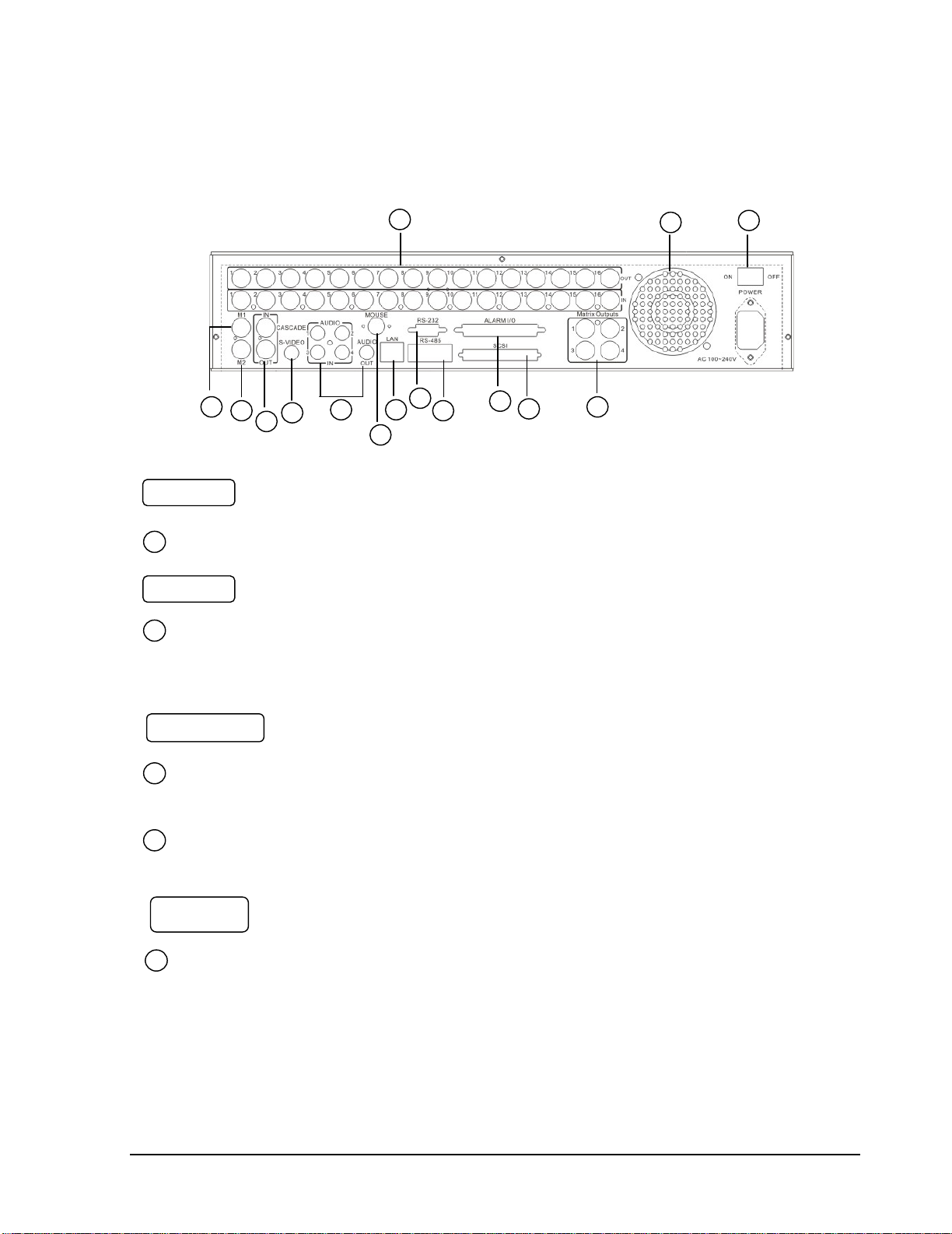
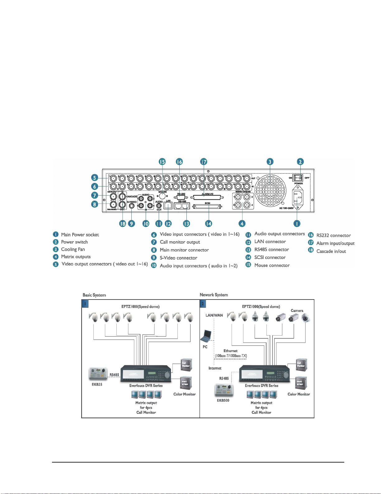
1.4 BackPanel Connections
1
2
3
4
5
6
7
8
9
10
11
12
13
14
15
Audio IN: Audio inputs 1~4 for recording, and it can be set to “YES” or “NO”
in the RECORD SETUP MENU.
Audio OUT: Connect an audio output to a monitor or other device.
AUDIO
1
2
Main Power plug: power source to AC 100~ 240V.
POWER
MAIN MONITOR: This connector is used for the main monitor display, a
number of different display modes may be selected for viewing.
CALL MONITOR: This connector is used for the call monitor. This monitor
can only display a full screen.
MONITOR
3
4
For EDR1640/1620 Series:
VIDEO OUT(1~16): Top row BNC connectors for video looping out 1~16.
VIDEO IN(1~16): Bottom row BNC connectors for video input 1~16 .
VIDEO IN
5
Page 18

8
LAN Connector: The RJ-45 network connection.
LAN
7
RS232
RS232 connector: D-Sub 9 pin connector for testing purposes only.
8
RS485
RS485 connector: RJ 45 Connector for RS485 control (via EKB500 controller)
and for multi Digital Video Recorder cascade.
9
For EDR920 Series:
VIDEO OUT(1~9): Top row BNC connectors for video looping out 1~9.
VIDEO IN(1~9): Bottom row BNC connectors for video input 1~9 .
ALM-INPUT: Normal open or normal close type alarm signal inputs.
The Alarm Input can be selected as normal open (N.O.) or normal close
(N.C.) input in the ALARM SETUP MENU. When an alarm occurs,
alarm recording will automatically start.
ALM-OUTPUT: A built-in relay offers 3 nodes which areALM-COM (common),
ALM-NO (normal open) and ALM-NC (normal close) for external use.
Note: Please check Chapter 3.4 and APPENDIX C to see other available alarm
input/output functions.
Alarm Input/Output
6
Alarm Input
FAN
10
FAN: Cooling FAN.
Page 19

9
Matrix outputs 1~4: BNC connectors for Matrix monitor outputs 1~4.
Matrix Outputs
SCSI Connector: For connecting the optional EDA800 storage expansion.
SCSI Connector
Mouse: PS/2 connector for mouse input.
Mouse
S-Video: PS/2 connector for S-Video monitor output.
S-Video
Cascade
11
12
13
14
15
Cascade is designed for connecting a number of DVRs to one monitor.
You will be allowed to view and to control as many DVRs as you prefer from the
same monitor simply switching the screen using a multi-function keyboard controller.
Connect from Cascade out of the DVR to Cascade In of another with BNC
connectors. Repeat the same step for all your DVRs until you connect the last Cascade
Out to the original DVR’s Cascade In.
Page 20
10
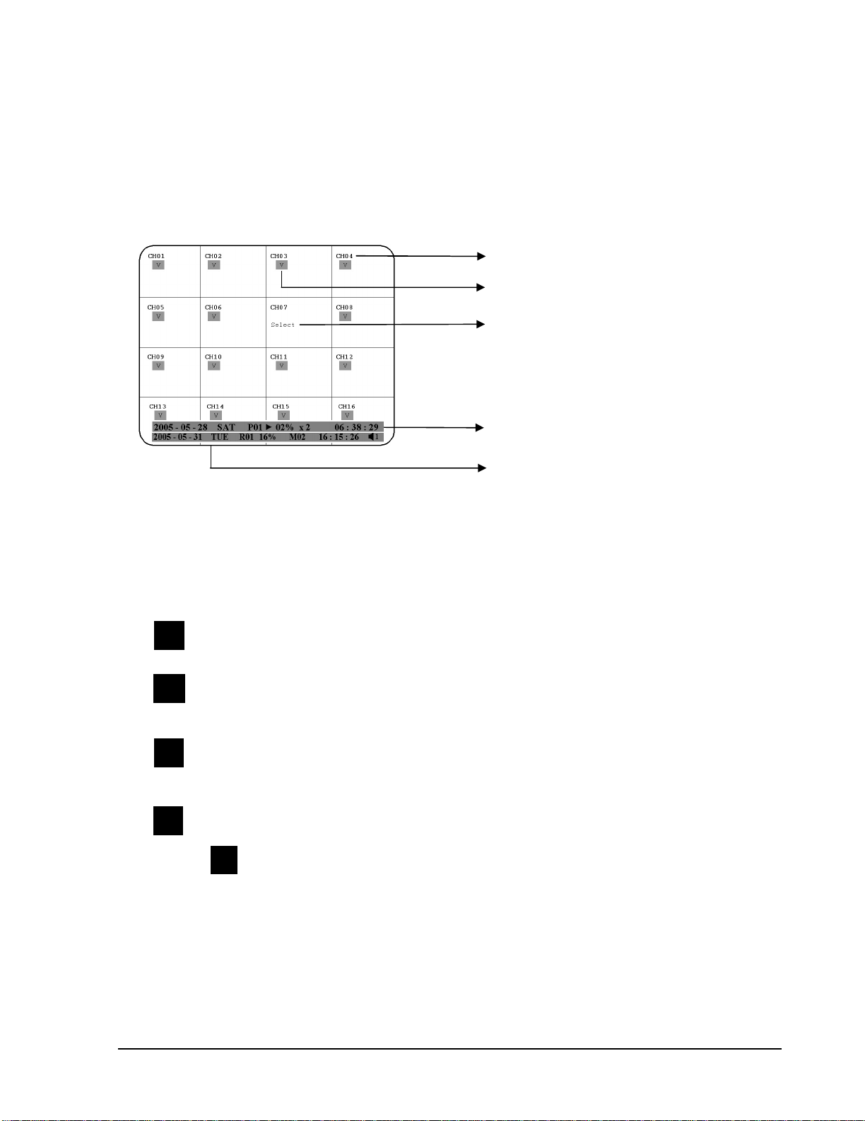
1.5 Monitor Display
1. Channel tag
2. Event sign
3. Select sign
4. Play status bar
5. Record status bar
The status information of the cameras or machine will show up, and be located at
different places on the screen.
2. Event sign: Event signals which are small icons with a capital letter and red
background show the events on each screen.There are a total of 6 different signals:
Alarm event. In order to show the camera video to a corresponding alarm,
setting a FOCUS CAMERA in ALARM SETUP MENU is necessary.
Motion event. Motion event only shows up when the camera’sMOTION is
enabled in MOTION SETUP MENU, and the camera detects a motion.
Video loss event. Video loss event only shows when the camera’s
VIDEOLOSS is enabled in VIDEOLOSS SETUP MENU, and the
camera signal is lost.
Sequence sign. Sequence sign shows up when the display is in the sequence
mode. The last display on the screen has a “*” sign in the top-middle. The
sign will replace the “*” in the display when sequence occurs.
Note: Sequence is invalid when all cameras are showing.
M
A
V
S
1. Channel tag: A channel tag indicates the channel name of the screen.
S
Page 21

11
Temperature indication.This shows if the hard drive’s temperature is overheated.
Overheat is determined in HDD TEMPERATURE of WARNING SETUP
MENU.
Fan fail indication. This shows when the fan fails to work normally. If you get this
warning, contact technical support for assistance.
3. Select sign: You can assign a camera to a display by pressing SELECT key in live mode.
Dial Jog to move the select sign to the display you would like to change camera, and then press
channel key on the front panel to choose that channel. PressSELECT again to exit from this
mode.
4. Play status bar: The play status bar appears in play back mode if you enable a status bar on
the screen (Please see DISPLAY, 8th item of Front Panel Keypads). There are three parts that
will be shown: play date, play status, and play time.
Play date
The date on which the video was recorded.
Play status
“PAUSE”, when the video playback is paused.
“P## >” means normal play speed on the displayed disk number;
“P## <“ means normal reverse play speed on the displayed disk number;
“>> x N” means N time fast play speed;
“<< x N” means N time fast reverse play speed.
Play time
The play time at which the video is recorded. The time format depends on the time
format setting in the TIME/DATE SETUP MENU.
5. Record status bar
The record status bar appears when you enable a status bar on the screen.
Play Date Play Status Play Time
Current Date Record Status Event Current Time Audio Ch
HDD/Fan Status
T
F
Page 22

12
1. Current date
The current date which is set in the TIME/DATE SETUP MENU.
2. Record status
Displays current Hard Drive and record position.
R01: currently recording on Disk 1
16%: currently recording at 16% of total HD position
NOTE: Percentage only indicates the physical point of recording on the Hard
Drive, not the total disk space used. To review the total amount of recording
time, please refer to the Disk Menu (Chapter 3.9)
3. Event
The current/last event that occurred.
4. Current time
The current time which is set in the TIME/DATE SETUP MENU.
5. Audio Ch
Displays which audio channel is currently active. This can be changed by turning the
Jog wheel in the live camera mode.
6. HDD/Fan status
“No Disk”: only shows when no disk is installed or detected.
“No Fan”: only shows when internal fan stops working.
“HDD OT”: only shows if hard drive is over temperature.
Page 23
13
2. Installation
The installations described below should be made by qualified service personnel or system installers.
Please check accessories in the packaging before beginning installation.Please refer to the following
diagram for the basic wiring connections.
Note: Monitors and Cameras must be purchased separately.
Diagram 2.1
Diagram 2.2
Chapter
2
Page 24
14
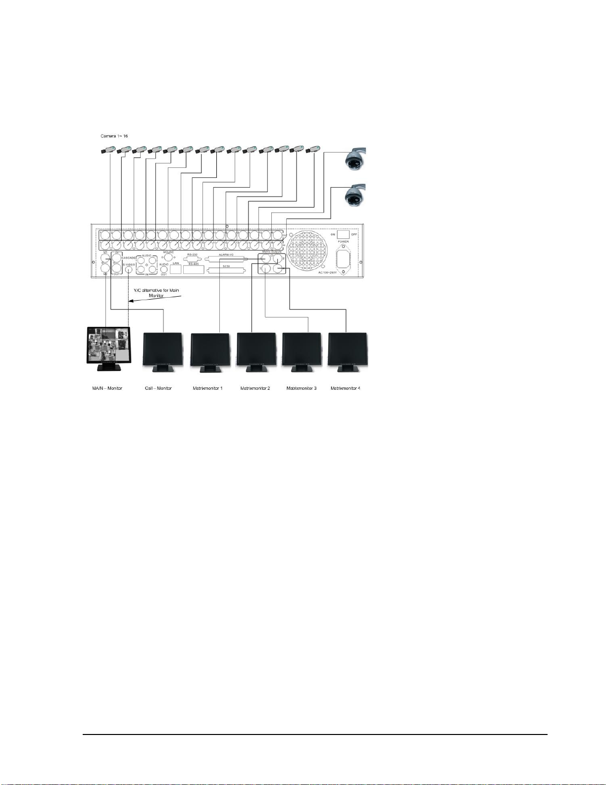
2.1 Video Connections, DVR cascading
Sample installation with maximum camera and monitor configuration:
Diagram 2.3
Cameras and monitors have to be cabled with 75 Ohm video cable, e.g. RG-59, RG-6, RG-11 and
suitable BNC plugs.
Due to inappropriate absorbability, 50 Ohm coax cable (e.g. RG58), antenna cable and further types
of coax cable are not suitable.
All connected videosources must provide a 1 Vpp NTSC standard video signal.
When interconnecting transmission lines (twisted pair, fibre optics, radio) to the video inputs, ensure
the accurate receiver calibration.
The MAIN monitor may optionally be connected through a Y-C (S-Video) cable to achieve an
improved image quality.
For local DVR operation, MAIN monitor connection is compulsory. Call and matrix monitors can be
connected optionally.
ATTENTION: Make sure that there is a video signal on video input 1 upon start-up, as this input is
required for video system auto detection (NTSC/PAL)!
Page 25
15
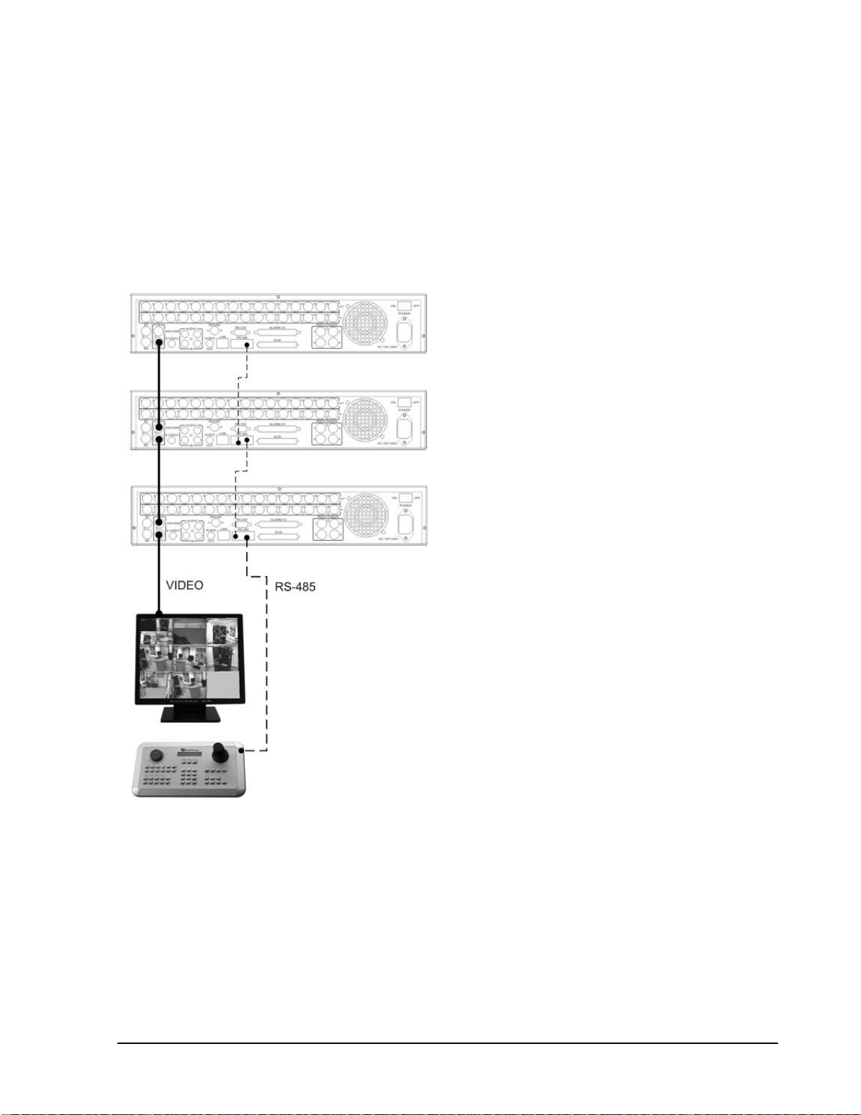
DVR Cascading
The digital video recorders provide "CASCADE IN" and "CASCADE OUT" video connections.
In combination with EKB500 keyboard, up to 255 EDR1640/1620/920 can be cascaded and
administrated via one single main monitor. Cascading is effected by connecting the DVRs
“CASCADE OUT” to the “CASCADE IN” of the following DVR, while the last “CASCADE OUT”
is connected to the monitor input.
Diagram 2.4
Installation with 3 cascaded EDR and EKB-500
Page 26
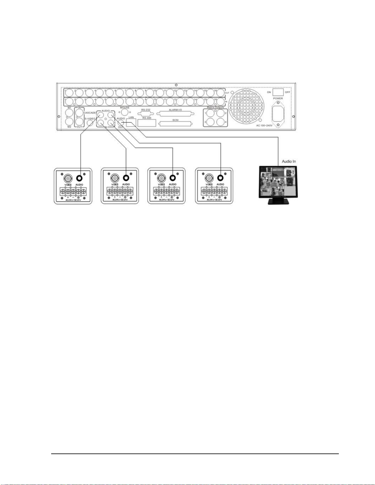
16
2.2 Audio Connection Installation
Sample installation with audio connection to video cameras providing audio output:
Diagram 2.5
The EDR1640/1620/920 DVRs provide 4 audio inputs and 1 audio output.
The inputs are designed for max. 500 mV to 10 KOhm line audio signals.
ATTENTION: The direct connection of a non-amplified microphone is not supported (a microphone
amplifier is required).
The installation has to be effected with audio coax cable and RCA plugs.
The output provides a max. 500 mV to 10 KOhm line audio signal and may be connected to e.g. a
monitor‘s audio input. The direct connection of (passive) speakers is not supported.
AUDIO RECORDING FUNCTIONALITY:
Audio recording is activated / deactivated in the RECORD menu for all channels.
Audio of all channels is always recorded together with (each) video and is independent of the image
recording rate. There is no specific camera allocation.
During playback, use the JOG to select the requested playback channel 1~4 (active channel is
indicated in playback on-screen display).
Page 27
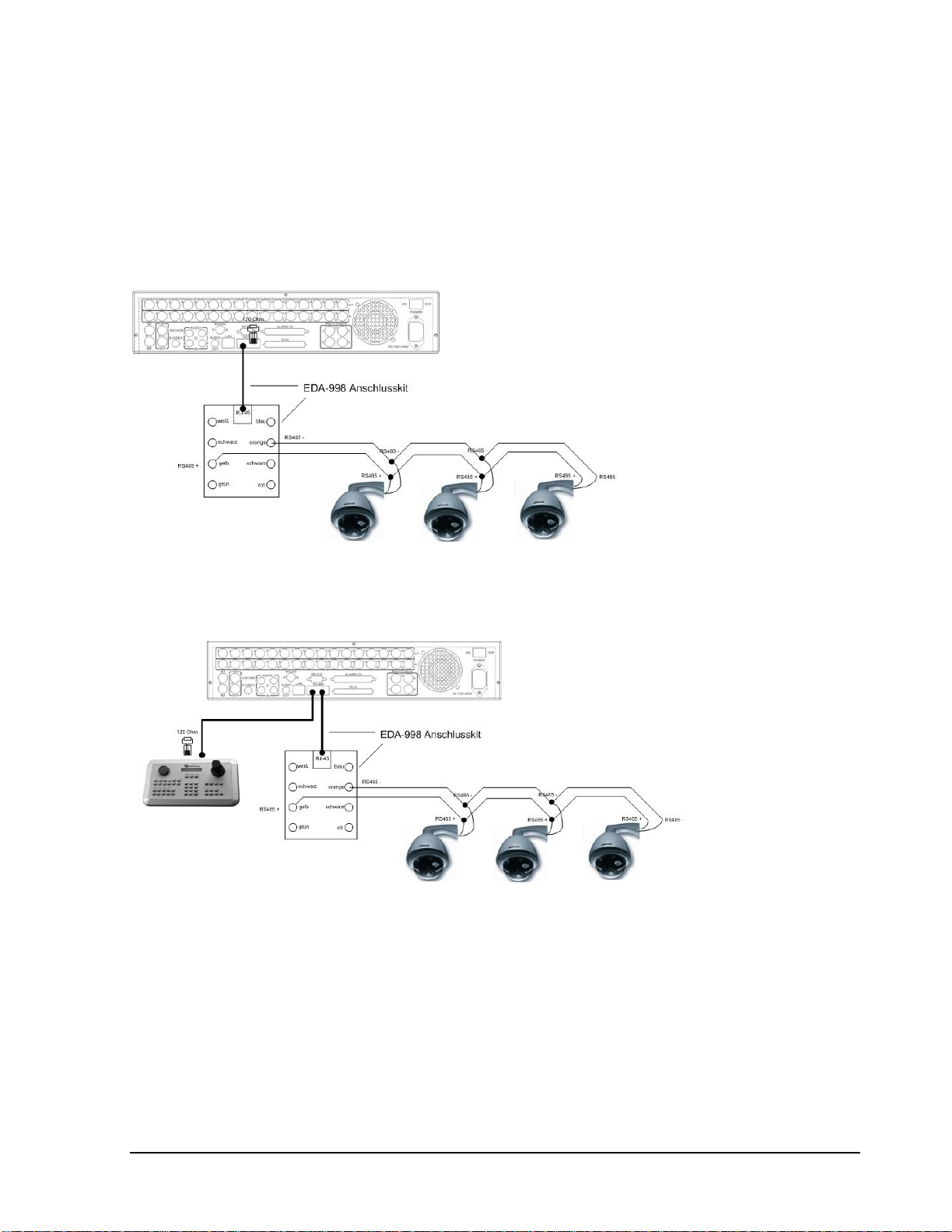
17
2.3 Speed Dome Installation
Speed dome or telemetry receiver pan/tilt/zoom control is available through web browser or the
optional PowerCon software if the DVR is connected to a network. Local telemetry control is
provided by the optional EKB 500 keyboard.
Supported protocols: EverFocus, Pelco-D, Pelco-P, ED2200/2250
Diagram 2.6
Sample installation with 3 EPTZ1000 speed domesand EDA998
Diagram 2.7
Sample installation with 3 EPTZ1000 speed dome, EDA998 and local EKB 500 operation
Required DVR settings: RS-485 receiver address inCAMERAmenu; RS-485 parameters and
protocol inCONTROLmenu
Page 28

18
ATTENTION:Some Pelco-D /-P protocol domes and receivers require an address offset of-1. In
other words, the address assigned to the dome / receiver in the DVR camera menu must be 1 below
the address set in the dome / receiver itself! (i.e. DVR ID: 2, PTZ ID: 3)
2.4 Alarm Input / Output Installation
The EDR1640/1620/920 alarm inputs can be used for recording start or recording rate adjustment.
Furthermore, alarm reactions such as camera switching to monitors, buzzer, e-mail and network alarm
are available. An alarm output relay can be switched if required.
EDR920 provides 9 alarm inputs, EDR1640/1620 provides 16. All inputs are programmable NO/NC.
Inputs have to be switched through dry contacts.
The 4 output relays provide a dry NO/NC contact.
All settings are programmed in theALARMmenu.
Use either the 37-pin Sub-D plug or the included adaptor board for connection.
Pin assignment adaptor board Pin assignment sub-d board
HOST
PIN #
NAME
PIN #
NAME
1
GND21GND
2
ALMIN 1
22
ALM_NC1
3
ALMIN 2
23
ALM_NO1
4
ALMIN 3
24
ALM_COM1
5
ALMIN 4
25
ALM_NC2
6
ALMIN 5
26
ALM_NO2
7
GND
27
ALM_COM2
8
ALMIN 628GND
9
ALMIN 7
29
ALM_NC3
10
ALMIN 8
30
ALM_NO3
11
ALMIN 9
31
ALM_COM3
12
ALMIN 10
32
ALM_NC4
13
GND33ALM_NO4
14
ALMIN 11
34
ALM_COM4
15
ALMIN 1235GND
16
ALMIN 13
36
ALMRST
17
ALMIN 14
37
REC_IN
18
ALMIN 15
38
SPARE_IN
19
ALMIN 16
39
DISK_FULL
20
GND
40
SPARE_OUT
DVR
PIN
NAM
PIN
NAM
1GN19
GN
2
ALM 1
20
ALM-NC03ALM 2
21
ALM-NO
4
ALM 3
22
ALM-COM0
5
ALM 4
23
ALM-NC1
6
ALM 5
24
ALM-NO
7
ALM 6
25
ALM-COM1
8
ALM 7
26
ALM-NC2
9
ALM 8
27
ALM-NO
10
ALM 9
28
ALM-COM2
11
ALM 10
29
ALM-NC3
12
ALM 1
130ALM-NO
13
ALM 12
31
ALM-COM3
14
ALM 13
32
ALMRSTO
15
ALM 14
33
REC16ALM 15
34
GIN1
17
ALM 16
35
DISKFULL
18GN36
GO
Page 29

19
Descriptions:
ALMINxx: Alarm input xx (1~16)
GND: common ground for alarm inputs
ALM_COMx: output relay x , contact root
ALM_NOx: output relay x , NO contact
ALM_NCx: output relay x , NC contact
ALMRST: Alarm reset, control input for alarm reset, for dry NO contact towards GND
DISKFULL: OC output contact for signal HDD full, switches to GND
REC_IN: Control contact for recording start
SPARE_IN / OUT:System error output. TTL-level 5VDC indicates "System Okay" status. The
contact will switch to open state, if one (ore more) of below listed events appears:
a) HDD full (If overwrite mode in RECORD menu is set to STOP)
b) No HDD
c) Over-temperature HDD
d) Power Loss
e) Cooler fan fault
f) Video Loss
g) Record off
Output level:
HIGH (5 V DC): System okay
Open state: System error
Page 30

20
SPARE_IN: N.O. Control input for playback function, playback is active as long contact is
closed.
NO contact alarm input connection:
NC contact alarm input connection:
Output relay in idle state:
Page 31

21
2.5 EDA800s Installation (optional)
The EDR1640/1620/920 image storage capacity can be expanded using EDA800s hard disk
expansion units. Max. 6 EDA800s with 8 hard disks each can be connected via SCSI bus.
Diagram 2.8
For installation details of the EDA-800S hard disk expansion unit, please refer to the EDA800s
manual.
2.6 Network Connection
EDR920/1620/1640 DVRs provide fast MPEG-4 format image transmission and network remote
configuration.
This chapter doesn‘t go into basic networking. For further information, about router installation and
internet connection please refer to the Chapter 10 through chapter 13.
Physically, two basic types of connection are possible:
2.6.1. Direct PC connection through crossover network cable
Diagram 2.9
The point-to-point connection of DVR and PC requires a crossover (crossed) network cable. This type
of connection does not allow the connection of several PCs or DVRs.
Make sure that the PC is equipped with a 100 Mb compatible network connection.
Page 32

22
2.6.2. Network connection through patch cable
Diagram 2.10
The connection to an existing network requires a normal patch cable (straight-through). The
illustration shows the connection to a network switch, router or modem.
2.6.3. Network system requirements
Connection type: 100Base-T
Max. required network bandwidth: 10 Mb
Protocol types: TCP, UDP, SMTP, HTTP, NTP
Required ports: for port configuration, please refer toNETWORK menu
2.7 Hard Disk Drive Installation
The first step in installing the hard drive is to insert the hard drive sleeve into the machine. The
second step is to insert the key provided and turn it to the lock position. If this process is ignored the
hard disk drive will not be detected. Follow the previous steps for the second hard drive or second
empty sleeve.Both hard drives should be setto MASTER. Otherwise,they will not be detected.
Note: A HDD should be installed before EDR1640/1620/920 is booted, or the
EDR1640/1620/920 will not detect a HDD until you reboot it with a HDD. Please make
sure the green HDD indicator light is ON. If the Hard Disk Drive is not locked in with the
keythe Hard Drive will not being recognized and the DVR will not go into record mode.
Note: After powering on the DVR, it will start to load system. It takes a while to
complete loading system; during this time, please do not install or remove the hard disk.
No action is recommended while the machine is loading system.
Page 33

23
2.8 Final Install Process
Once you have completed the basic wiring installation and the hard disk drive installation you are
ready to turn on the DVR. Simply plugin the power source and turn the switchto theon position. The
POWER LED lights will light up if power is normal. Once the system has finished loading, the next
step is to set up the menu options for the DVR.
Diagram 2.11shows 3.5“ Hard Drive
Page 34

24
3. DVR Menu Setup
Assuming you have completed the first two chapters of this manual, you are now ready to begin
setting up the digital video recorder. The following chapter will walk you through the detailed DVR
Menu step by step and how to set the DVR for your specific application. To begin this process, press
theMENU key. Once inside the main menu you will find there are 12 setup option pages as follows.
PressMENU key to enter the MAIN MENU.
Press MENU key or click on the arrow at the top right corner of the
screen with a mouse to go back to the previous menu.
Dial the Jog clockwise or counterclockwise to change subentry values.
Press the ENTER key to go to next subentry in a menu setting, and press
the CALL key to go to previous subentry in a menu setting. Or, simply
use the left mouse click to go to a subentry in a menu setting and use
scroll wheel of the mouse to change the value.
Diagram 3.1
Chapter
3
MENU
Page 35

25
3.1 Time/Date Setup Menu
Diagram 3.2
Diagram 3.2 is a screen shot of the TIME/DATE SETUP MENU. This menu is used to set up the
correct time and date for your region of the world. You are able to setup daylight savings as well as
synch it with an internet based time server. In theTIME/DATE SETUP MENU the following fields
are defined as follows:
1. TIME FORMAT: This field represents the time format on the DVR. You can select between
12 HOUR and24 HOUR format.
2. TIME: This field represents the current time on the DVR. To change this, simply use the Jog
Dial on the DVR.
The Time is represented as follows:
Hour: 00~23(1~12 ifTIME FORMAT is 12 HOUR): Minute: 00~59: Second: 00~59
3. DATE FORMAT: This field represents the date format on the DVR. To change this, simply
use the Jog Dial on the DVR. There are three date formats which are YYYY-MM-DD, MM-
DD-YYYY and DD-MM-YYYY to be selected.
4. DATE: This field represents the date on the DVR. To change this, simply use the Jog Dial on
the DVR.
The date is represented as follows:
Year: 2000~2099 / Month: 01~12 / Date: 01~31/ Day of Week (automatically changes)
Page 36

26
5. DAYLIGHT SAVING: This field represents the daylight savings on the DVR. To change this,
simply use the Jog Dial on the DVR. Select “ON” or “OFF” to enable or disable daylight saving
time function. In order to set a daylight saving time zone, you need to disable daylight saving
first. Enable the daylight saving after finish setting the time zone.
6. START TIME
To set the start time of daylight saving time.
To set the start month of daylight saving time: Dial the jog to set the start month.
To set the start week of daylight saving time: Dial the jog to set the start week.
To set the start day of daylight saving time: Dial the jog to set the start day.
To set the starting time change of daylight saving time: Choose when the time changes
from the old time (FROM) to the new time (TO) when daylight saving starts.
7. END TIME:To set the end time of daylight saving.
To set the endmonth of daylight saving time: Dial the jog to set the end month.
To set the end week of daylight saving time: Dial the jog to set the end week.
To set the end date of daylight saving time: Dial the jog to set the end date.
LAST
1 ST
2 ND
3 RD
4 TH
FEB
MAR
JAN
APR
MAY
JUN
DEC
NOV
OCT
SEP
AUG
JUL
LAST
1 ST
2 ND
3 RD
4 TH
THU
SUN
TUE
MON
WED
SAT
FRI
THU
SUN
TUE
MON
WED
SAT
FRI
FEB
MAR
JAN
APR
MAY
JUN
DEC
NOV
OCT
SEP
AUG
JUL
Page 37

27
To set the ending time change of daylight saving time: Choose when the time changes from
the old time (FROM)to the new time (TO) when daylight savingends.
8. TIME SYNCHRONIZE
Select “ON” or “OFF” to enable or disable time synchronize, which will update the correct time
automatically when network is connected. To change this, simply use the Jog Dial on the DVR.
9. TIME SERVER
You can set the time server address that the DVR connects to for time synchronize. To find the IP
address of NTP Server, please follow these steps:
a) Go to a PC that is connected to the internet.
b) Click on “START” -> “RUN”-> type “cmd”-> press “OK”.
c) In the Dos Prompt, type “ping pool.ntp.org” to find out the IP address of an NTP Server.
Diagram 3.3
10. TIME ZONE
You can set the time zone that the DVR adjusts to when updating from the time server.
Atlantic Daylight Time subtract 3 hours from GMT
Atlantic Standard Time subtract 4 hours from GMT
Eastern Daylight Time subtract 4 hours from GMT
Eastern Standard Time subtract 5 hours from GMT
Central Daylight Time subtract 5 hours from GMT
Central Standard Time subtract 6 hours from GMT
Mountain Daylight Time subtract 6 hours from GMT
Mountain Standard Time subtract 7 hours from GMT
Page 38

28
Pacific Daylight Time subtract 7 hours from GMT
Pacific Standard Time subtract 8 hours from GMT
Alaska Daylight Time subtract 8 hours from GMT
Alaska Standard Time subtract 9 hours from GMT
Hawaii-Aleutian Daylight Time subtract 9 hours from GMT
Hawaii-Aleutian Standard Time subtract 10 hours from GMT
11. TIME UPDATE BY
Once you enable theTIME SYNCHRONIZE, you can select the synchronization frequency
by:
DAY
MONTH
WEEK
Page 39

29
3.2 Camera Setup Menu
Diagram 3.4
Diagram 3.4 is a screen shot of theCAMERA SETUP MENU. This menu will walk you through
setting up the Camera Recording Speeds, Camera titles, covert modes, and recording quality. In the
CAMERA SETUP MENU the following fields are defined as:
1. TITLE: The title setting allows you to assign a title to each camera input. Each channel
supports a title with up to 12 characters. Press Enter to move to each character and use the Jog
Dial to change the value. The available alphanumeric characters are:
0,1,2,3,4,5,6,7,8,9,
A,B,C,D,E,F,G,H,I,J,K,L,M,N,O,P,Q,R,S,T,U,V,W,X,Y,Z,
( ) . , +- / and an empty space.
2. PTZ ID: Select PTZ ID/Address from 001~255 or OFF.OFF is the same as 000. This ID must
match the ID used by the PTZcamera. To change this, simply use the Jog Dial on the DVR.
3. INSTALL/COVERT: For installation of camera, select “ON” to enable a camera, and “OFF”
to disable it. Please make sure to stop recording before making change to INSTALL. For
optimum recording performance, switch any unused camera channels to OFF in this section.
For covert, select “ON” to cover a camera and disable the screen in live mode. However, the
image is recorded, and can be viewed in playback mode. Covert channels will not show up on
the sequence mode. To change these, simply use the Jog Dial on the DVR.
Page 40

30
4. SEQ (MAIN/CALL): Set the dwell time for sequences on the Main or Call Monitors. To
change this, simply use the Jog Dial on the DVR.
5. REC QUALITY: Select an image quality for recording. There are six different qualities
available. A higher image quality uses more HDD space. To change this, simply use the Jog
Dial on the DVR.Theestimated space needed per second lists below:
720x480
Video Source
Simple:
Complex:
LOWER:
8.04KB
12.33KB
LOW:
8.42KB
13.7KB
BASIC:
10.15KB
16.72KB
STANDARD:
11.86KB
19.56KB
HIGH:
14.72KB
24.63KB
Average size
per image
SUPERIOR:
18.60KB
30.05KB
720x240
Video Source
Simple:
Complex:
LOWER:
3.53KB
7.82KB
LOW:
3.87KB
8.36KB
BASIC:
4.21KB
8.9KB
STANDARD:
4.92KB
9.54KB
HIGH:
5.62KB
10.17KB
Average size
per image
SUPERIOR:
6.41KB
12.89KB
360x240
Video Source
Simple:
Complex:
LOWER:
1.76KB
4.56KB
LOW:
1.87KB
4.87KB
BASIC:
1.97KB
5.46KB
STANDARD:
2.38KB
6.51KB
HIGH:
2.67KB
7.08KB
Average size
per image
SUPERIOR:
3.63KB
9.02KB
Note:Since the compression ratio of MPEG4 depends on the variation and complexity of the
recorded video, the table above is for your reference only.
Page 41

31
6. REC SPEED & ACTION:
TP: Scheduled recording time 1~8 which can be set in the SCHEDULE SETUP MENU.
“N” is the normal recordingperiod, which is activated by pressing the Record button. If you
have set a Time Period in Schedule Setup Menu, then there will be a star sign (*) beside that
TP in Camera Setup Menu.
NORMAL: IPS recording rate for constant recording and recording triggered through “REC
IN” input contact. The maximum image rate is limited to the maximum recording rate divided
by the number of installed cameras.
EVENT: IPS recording rate for motion or alarm events. Event record speed can be set from 1
to 30 IPS (25 for PAL) or “OFF”.
Note: In order to activate a new record speed, you need to disable all current record actions
and then turn them back on.
ACTION
Set “ON” to activatemotion action on a Time Period.
Set “OFF” to disablemotion action on a Time Period.
This setting correlates closely with Motion Setup. If motion setting is disabled, motion
detection will not function regardless if Action in Camera Setup Menuis ON or OFF.
However, if Motion setting is enabled, then motion detection function works depending on
Action setting in Camera Setup Menu. All motion actions (including buzzer, relay, network
alarm, e-mail and log) will be triggered if they are enabled in Motion Setup Menu as long as
Action is “ON” for the TP (Time Period) you have set. If you do not wish to have motion
detected for a specific time, set Action “OFF” for that Time Period. This function gives you
flexibility to set motion detection function ON or OFF for different Time Periods.
Page 42

32
7. SUMMARY :
Diagram 3.5
Dial Jog to change items in theSUMMARY table.
All cameras’ statuses are shown in the SUMMARY table. The table is for checking camera
overall statuses only, not for setting.
Note: The SUMMARY table also exists in ALARM, MOTION and VIDEOLOSS SETUP
MENU. All of theseSUMMARY tables are also for checking particular overall statuses, not for
setting.
8. Copy camera’s setting from a camera to other cameras: In order to quickly copy the setting
from one camera to other cameras, we provide a copy function for camera settings. Highlight
the desired camera from the list on the left, and then pressCOPY. COPIED will show up in the
top right corner of the screen. Dial the Jog to the camera you would like to copy to, and then
pressSEARCH to paste. The previous settings of the camera will be overwritten, and PASTED
will be displayed in the top right corner.
Note: TITLE, PTZ ID, and INSTALL/COVERT cannot be copied. These 3 options must be set
independently.
Page 43

33
3.3 Record Setup Menu
Diagram 3.6
Diagram 3.6 is a screen shot of the RECORD SETUP MENU. This menu is for setting up
the options for recording audio and video. In the RECORD SETUP MENU the following
fields are defined as follows:
1. RECORD AUDIO:
YES: Audio will be recorded when machine is recordingand a microphone is present.
NO: Audio will not be recorded when machine is recording.
2. TIME STAMP:
ON: The time stamp will show on the video and picture when recording.
OFF: The time stamp will not show on the video and picture when recording.
3. TIME STAMP POSITION:
BOTTOM:The time stamp will show on the bottom.
TOP: The time stamp will show on the top.
Page 44

34
4. WATER MARK:
ON:Recording is overlaid by a visible watermark (“W”).
OFF:No watermark.
5. RESOLUTION: The resolutions for NTSC are 720x480, 720x240 and 360x240. The default
value is 720x240. The resolutions for PAL are 720x288, 720x576 and 360x288. The default
value is 720x288.
Note: Selecting a certain resolution will determine the amount of IPS the DVR will support.
NTSC
720x480 =120 IPS (EDR1640) or 60 IPS (EDR1620/920)
720x240 = 240 IPS (EDR1640) or 120 IPS (EDR1620/920)
360x240 =480 IPS (EDR1640) or 240 IPS (EDR1620/920)
6. RECORD MODE:
REWRITE:Continue recording. Disk will begin overwriting when it is full.
STOP: Stop recording when disk is full.
7. AUTOWRITE WITHIN: You can set DVR to automatically overwrite after the selected
number of days. If you do not wish to use this function,simply select “0”.
8. PRE-ALARM RECORDING
Select “YES” to enable pre-alarm recording function. Select “NO” to disable pre-alarm
recording function.
9. RELAY OUT
By selecting “1”, user can easily identify whether DVR is recording or not if relay output is
connected to a signaling device. Select “NONE” if you do not wish to identify recording
status.
Page 45

35
3.4 Alarm Setup Menu
Diagram 3.7
Diagram 3.7 is a screen shot of the ALARM SETUP MENU. An alarm is defined as an electronic
or mechanical device that sends a warning signal under specific circumstances. In this case the
signal triggers the recorder to start recording the alarmed event. This menu contains all the alarm
operations and options needed to successfully complete an alarm recording. In the ALARM
SETUP MENU the following fields are defined:
1. ALARM
This field is to turn alarm detection on or off. The default value is ENABLE. To change this,
simply use the Jog Dial on the DVR.
ENABLE: Enable alarm detection.
DISABLE: Disable alarm detection.
2. ALARM TYPE
This field is to change the type of alarm recording. The default value is N.O. To change this,
simply use the Jog Dial on the DVR.
N. O.:Normal Open alarm.
N. C.: Normal Close alarm.
N.O. Trans.: When the alarm is triggered, buzzer, alarm output and alarm recording remain
active until alarm is set back to N.O.
N.C. Trans.: When the alarm is triggered, buzzer, alarm output and alarm recording remain
active until alarm is set back to N.C.
Page 46

36
3. LOG
YES: Select YES if you wish to record Alarm Events in the Log.
NO: Select NO if you do not wish to record Alarm Events in the Log.
4. ACTIVE CAMERA
This field is to activate camera you want to have the alarm enabled too. For example if you had
an external motion detector on camera one you would set this option to camera one. The Default
setting is the same camera number as the current alarm. To change this,simply use the Jog Dial
on the DVR.
5. PTZ PRESET
SelectPTZ PRESET from “001” to “255”, so that when Alarm occurs, speed dome will turn to
a preset position for event recording. This function improves surveillance quality of an alarm
event. If you wish to disable this function, simply select “OFF”.
6. DURATION
1~99 SEC: The amount of time alarm recording, screen change, buzzer and output contact will
last. Adjustable from 1~ 99 seconds.
TRANSPARENT: Continuous recording, screen change, buzzer, and output contact for a
triggered alarm event.
7. ALARM OUTPUT
This will transmit a signal to another device. The setting of alarms are NONE = not activated,
1 = output signal 1 transmits, 2 = output signal 2 transmits, 3 = output signal 3 transmits
and 4 = output signal 4 transmits.
8. ALARM EMAIL
Select “YES” to send an email when alarm occurs or “NO” to disable alarm email. The email
address can be set in theNETWORK SETUP MENU.
9. BUZZER:Audible alarm buzzer.
ENABLE: To enable the alarm buzzer.
DISABLE: To disable the alarm buzzer.
10. ALARM NETWORK
YES: Enable alarm network.
NO:Disable alarm network.
11. MAIN MON:Display on main monitor when an alarm occurs.
NO CHANGE: No change on the main monitor display when an alarm occurs.
FULLSCREEN: A full screen of the active camera will display when an alarm occurs.
Page 47

37
12. CALL MON:Display on a call monitor when an alarm occurs.
NO CHANGE: No change on thecall monitor display when an alarm occurs.
SEQUENCE: Display in sequence mode on call monitor when an alarm occurs, according
to sequence duration set in Camera Setup Menu.
ACTIVE CAMERA: Display the active camera in full screen mode to the call monitor
when an alarm occurs.
13. SUMMARY
Dial Jog to change items in the SUMMARY table. All alarms’ statuses are shown in
SUMMARY tables. These tables are for checking overall alarm statuses, not for changing
them.
Page 48

38
3.5 Motion Setup Menu
Diagram 3.8
Diagram 3.8 is a screen shot of the MOTION SETUP MENU. We define motion as a change of
pixilation in the field of view, which is detected by the digital video recorder and triggers the recorder
to start recording. This menu is for setting up the digital recorder for motion recording on a per
camera basis.
In theMOTION SETUP MENU the following fields are defined as follows:
1. MOTION
This field is to turn motion detection on or off. The default value is DISABLE. To change this,
simply use the Jog Dial on the DVR.
ENABLE: Enable motion detection.
DISABLE: Disable motion detection.
Note:Motion only works in live and playback modes. It is invalid while in menus.
2. SENSITIVITY
The sensitivity allows users to adjust to a suitable motion detection sensitivity. There are 10
sensitivities available; level 1 is the lowest, and level 10 is the highest. To change this, simply
use the Jog Dial on the DVR.
Page 49

39
3. LOG
YES: Select YES if you wish to record Motion Events in the Log.
NO: Select NO if you do not wish to record Motion Eventsin the Log.
4. DURATION
The amount of time a motion event will record- from 1 sec to 99 seconds. The default value is 5
seconds. To change this, simply use the Jog Dial on the DVR.
5. ALARM OUTPUT
This will transmit a signal to another device. The setting of alarms are NONE = not activated, 1
= output signal 1 transmits, 2 = output signal 2 transmits, 3 = output signal 3transmitsand
4 = output signal 4 transmits. To change this, simply use the Jog Dial on the DVR.
6. ALARM EMAIL
YES: Send an email when an alarm occurs.
NO: Do not send an email when an alarm occurs.
The email address and email server can be set in theNETWORK SETUP MENU.
7. ALARM NETWORK
YES: Enable alarm network when an alarm occurs.
NO: Disable alarm network when an alarm occurs.
8. BUZZER:Audible buzzer when motion is detected.
ENABLE: To enable a motion buzzer.
DISABLE: To disable a motion buzzer.
9. MOTION DELAY:
Select motion delay time from 0~7 level.
10. MAIN MON:Display on main monitor when motion occurs.
NO CHANGE: No change on the main monitor display when a motion occurs.
FULLSCREEN: A full screen of the active camera will display when motion occurs.
11. CALL MON:Display on a call monitor when motion occurs.
NO CHANGE: No change on the call monitor display when motion occurs.
ACTIVE CAMERA: Display the active camera that is set for Motion in full screen mode
to the call monitor.
12. SUMMARY
Dial Jog to change items in the SUMMARY table. All alarm’s statuses are shown in
SUMMARY tables. These tables are for checking alarm overall statuses, not for changing them.
Page 50

40
13. MOTION AREA
Enter a desired channel and press SELECT or middle mouse button to edit a motion area.
MOTION must be set as “Enable”in order toedit the motion detection area.
To quit the motion area edit, press MENU or right-click the mouse to obtain a selection
menu, select “EXIT” by clicking the “+” or “-” sign. Then press “OK”.
To test a motion area: Grids will turn from green to red when motion is detected.
To clear the motion entire area: Press PLAY to clear the entire motion area.
If you forget the motion grid commands: Press CALL to display a hint window (shown
below).
In the motion edit mode:
The default motion area of each camera is
entire screen which displays in light green.
Press COPY or left-click the mouse to start
setting an area.
Use the JOG Dial to move the cursor. Press
ENTER to switch between vertical and
horizontal movement.
Press SEARCH to end and enable the
area, or press PAUSE to end and disable the
area.
Alternatively, right-click the mouse to obtain a
selection menu, then use the “+” or “-“ signs to
either select “ON” to enable the area or “OFF”
to disable the area, then click “OK”.
MENU
COPY
ENTER
SEARCH
PAUSE
- EXIT
- SELECT AREA
- CHANGE DIR
- ON AREA
- OFF AREA
Page 51

41
3.6 VIDEOLOSS Setup Menu
Diagram 3.9
Diagram 3.9 is a screen shot of the VIDEOLOSS (Video Loss) SETUP MENU. VIDEOLOSS
event is caused by no video signal input for the channel, usually when the camera fails or loses
power. How to set up system response for VIDEOLOSS is introduced in this section.
In the VIDEOLOSS SETUP MENU the following fields are defined as follows:
1. VIDEOLOSS:
ENABLE: Enable video loss detection.
DISABLE: Disable video loss detection.
2. LOG:
YES: Select YES if you wish to record Video Loss Events in the Log.
NO: Select NO if you do not wish to record Video Loss Events in the Log.
3. DURATION:
Duration of VIDEOLOSS buzzer ranges from 1 sec to 99 seconds. The default value is 5
seconds. To change this, simply use the Jog Dial on the DVR.
4. ALARM OUTPUT:
This will transmit a signal to another device. The setting of alarms are NONE = not activated, 1
= output signal 1 transmits, 2 = output signal 2 transmits, 3 = output signal 3 transmitsand
4 = output signal 4 transmits. To change this, simply use the Jog Dial on the DVR.
Page 52

42
5. ALARM EMAIL:
Select “YES” for sending an email when Video Loss event occurs. The email address can be set
in theNETWORK SETUP MENU.
6. BUZZER:Audible alarm buzzer.
ENABLE: To enable a VIDEOLOSS buzzer.
DISABLE: To disable a VIDEOLOSS buzzer.
7. ALARM NETWORK:
YES: Enable alarm network.
NO:Disable alarm network.
8. SUMMARY
All video loss’s statuses are shown in SUMMARY tables. These tables are for checking video
loss overall statuses, but not for changing them.
Page 53

43
3.7 Network Setup Menu
Diagram 3.10
Diagram 3.10 is a screen shot of the NETWORK SETUP MENU. This menu is for setting up the
configurations for networking to the DVR. There are 6 subentries in the NETWORK SETUP
MENU: CONFIG, ALARM, EMAIL, PASSWORD, PPPoE and DDNS. Please refer to the
Networking Chapter of this manual to fully understand how to setup your network for this DVR. In
the Network Setting Menu the following fields are defined as follows:
Note: Since every Network Configuration is different, please contact your Network Administrator
or ISP for how to assign those IP addresses and port numbers.
3.7.1 CONFIG
In the CONFIGof the NETWORK SETUP MENU,we define:
1. IP CONFIG:
FIXED IP:User can seta fixed IP for network connection.
DHCP:DHCP server in LAN willautomaticallyprovide the IP for network connection
PPPoE: This is a DSL connection application, ISP will ask user to input user name and
password. Before choosing this option, please go to PPPoE configuration menu for setting
PPPoE configuration.
Page 54

44
2. IP Address
This field shows the current IP Address for the DVR. A Fixed IP address does not change and
must be set manually. To change this, simply use the Jog Dial on the DVR. When DHCP is
selected, the DHCP server will assign this value automatically.
Note: The addresses in the machine are for our own testing you must apply your own addresses
to comply with your network. Refer to Networking Chapter for more details.
3. SUBNET MASK
This field is to set the subnet mask for your network so as the DVR will be recognized within
the network. Example: 255.255.255.000. To change this, simply use the Jog Dial on the DVR.
When DHCP is selected, the DHCP server will assign this value automatically.
4. GATEWAY
This field is to set the gateway for your network so the DVR will be recognized within the
network. To change this, simply use the Jog Dial on the DVR. When DHCP is selected, the
DHCP server will assign this value automatically.
5. DNS SERVER
This field is to set the DNS server for your network so the DVR will be recognized within the
network. To change this, simply use the Jog Dial on the DVR. When DHCP is selected, the
DHCP server will assign this value automatically.
6. REMOTE RELAY CONTROL:
YES: By selectingYES, system will accept remote command of relay control.
NO:By selectingNO, system will refuse remote command of relay control.
7. HTTP PORT
The default port number is 80. User can change it to different port number for HTTP/WEB
communication betweenDVR and client PC.
8. CONTROL PORT
The default port number is 1600. User can change it to different port number for controlling
authentication between DVR and client PC.
9. DATA PORT
The default data transmitting port number is 37260. User can change it to different port number
for data transfer between DVR and client PC.
Page 55

45
10. BW CONTROL
This configuration allows user to control the bandwidth of DVR.
11. MAC ADDR
This field is for those Internet service providers or Network administrators who require a MAC
address of the network card of the DVR. This option cannot be changed.
3.7.2 ALARM(NETWORK)
DVR can send out Alarm message to an Alarm Server. This function is reserved to work with our
Control Management System – PowerCon4. In the ALARM of the NETWORK SETUP MENU,
we define:
Diagram 3.11
Note: Since every Network Configuration is different, please contact your Network
Administrator or ISP for how to assign those IP addresses and port numbers.
1. PROTOCOL: Select which communication protocol with Alarm servers or Alarm receiving
clients.
TCP:communicate with client via TCP protocol.
UDP: communicate with client via UDP protocol.
2. PORT NUMBER:setting the communication port with Alarm server.
3. UNIQUE ID:setting the ID number of your DVR to Alarm server.
Page 56

46
4. SERVER 1:assign the IP address of Alarm server 1.
5. SERVER 2:assign the IP address of Alarm server 2.
6. SERVER 3:assign the IP address of Alarm server 3.
3.7.3 EMAIL
In the EMAIL of the NETWORK SETUP MENU,we define:
Diagram 3.12
In the EMAIL of the NETWORK SETUP MENU,we define:
1. SMTP SERVER
Assign the SMTP (e-mail) server’sname.
Note: For more reliable email service, use the server’s IP address.
2. PORT NUMBER
Assign the port number for SMTP server. The default port is 25.
3. AUTHENTICATION
Select “YES”, if the SMTP server requires Authentication (user name / password)
4. USER
Input the login user ID if the SMTP server requires Authentication.
Page 57

47
5. PASSWD
Input the password if the SMTP server requires Authentication.
6. RECEIV.EMAIL ADDR
Input the e-mail address for receiving e-mail messages when the EVENT is enabled and triggered.
Example: In Motion Setup Menu, if the “EMAIL/NETWORK” is set to “YES”, this e-mail
address will receive a message and a still image (in “ARV” format) from the DVR when Motion
is triggered. This “ARV” file can be played back by opening “DVRViewer.exe” which can be
downloaded from the DVR’s Network Viewer or from the Copy Menu.
7. SENDEREMAIL ADDR
Input sender’s e-mail address, so that receiver can recognize the sender when an event message is
sent out.
3.7.4 PASSWORD
In the PASSWORDof the NETWORK SETUP MENU,we define:
Diagram 3.13
In the PASSWORDof the NETWORK SETUP MENU,we define:
Name/Password/Level: This category is to set up the users that will log into the network. Please
remember that this portion of the Network setting menu is set up in column format.
The default User Name = ADMIN
The default Password = 11111111
Page 58

48
To change this, press Enter to move to each character and use the Jog Dial on the DVR to
change each character.Note that the password is limited tonumbers only.
There are 3 level types:
1. Admin: User has all the rights including viewing live video, performing a search, playback and
controlling the PTZ camera (if one is connected).
2. Play: User has the same rights as Admin user. Except PTZ programming and Remote
configuration are not authorized toPlay level users.
3. Live: Allows user only to view live video.
3.7.5 PPPOE
In the PPPOE of the NETWORK SETUP MENU,we define:
Diagram 3.14
In the PPPoE of the NETWORK SETUP MENU,we define:
1. USER
User name that is provided by ISP for PPPoE Connection
2. PASSWD
Password that is provided by ISP for PPPoE connection
3. PRIMARY DNS
IP address of DNS server that is provided by ISP.
Page 59

49
4. SECONDARY DNS
If your ISP provides you with a secondary DNS address, please set it in here.
NOTE:
Please complete all settings in the PPPoE Setup Menu before changing IP CONFIG to
PPPoE in the CONFIG options. If you make this change before completing PPPoE settings,
then the PPPoE function will not work.
3.7.6 DDNS
In the DDNSof the NETWORK SETUP MENU,we define:
Diagram 3.15
In DDNS of the NETWORK SETUP MENU,we define :
1. SERVER
DDNS provider (example: www.dyndns.com)
2. USER
User name of the account.
3. PASSWD
Password of the account.
Page 60

50
4. RECORD ID
Identity tag used by certain DDNS providers
5. FQDN
The domain name of this account.
NOTE: If using “EverFocusDDNS.com” as the server, there is less information required. For
more details on DDNS setup, see the Networking section of the manual.
Page 61

51
3.8 Schedule Setup Menu
Diagram 3.16
Diagram 3.16 is a screen shot of the SCHEDULE SETUP MENU. In this menu you can set a
unique timer to start recording from a specified start time to an end time. This menu works together
with theCAMERA menu; you will notice TP (time period) 1~8, which is also seen in the CAMERA
menu.
In theSCHEDULE SETUP MENU the following fields are defined as:
1. DAY
This field represents the day of the week you wish to set the timer record for. Initially it is set to
DLY as default. You may choose from MON-SUN as well as WDAY, WEND, and DLY. To
change this, simply use the Jog Dial on the DVR.
MON (Monday), TUE (Tuesday), WED (Wednesday), THU (Thursday), FRI (Friday), SAT
(Saturday), SUN(Sunday).
WDAY:Weekday, from Monday to Friday.
WEND:Weekend, Saturday and Sunday.
DLY: Daily, every day of the week.
2. START
This field is used to set the time you wish to start the timer recording. To change this, simplyuse
the Jog Dial on the DVR.
Page 62

52
Hour: 0 ~ 23in 24 hour time format; 1~12in 12 hour time format.
Minutes: 00 ~ 59
3. END
This field is used to set the time you wish to stop the timer recording. To change this, simply use
the Jog Dial on the DVR.
Hour: 0 ~ 23in 24 hour time format; 1~12in 12 hour time format.
Minutes: 00 ~ 59
Note: To record a 24-hour period: set 12:00am~12:00 am for 12-hour format; 00:00~00:00 for
24-hour format.
4. SET
This field is used to turn the timer recording on or off. To change this, simplyuse the Jog Dial on
the DVR.
ON:Enable a scheduled record time period.
OFF: Disable a scheduled record time period.
Page 63

53
3.9 Disk Setup Menu
Diagram 3.17
Diagram 3.17 is a screen shot of the DISK SETUP MENU. This menu is for viewing Disk
information and formatting the disks. For initial setup or major setup changes we recommend
formatting the Hard Disk.
In theDISK SETUP MENU the following fields are defined as follows:
1. DISKINFORMATION
Select disk information, it is selectable from 1 up to 50 disks, in intervals of 4. The total number of
hard drives varies by model.
2. DISK VIDEO DELETE
Press SELECT to start delete. A delete disk confirmation window will show up after
pressing SELECT button.
Dial the Jog to move highlighter to YES, and then press SELECT button; a deleting
indicator DELETE…… will show up. An indicator of success
SUCCESS…… will show up when delete is completed.
If you do not want to delete the disk after the delete disk
confirmation window shows up, you can move highlighter to
NO, and then press SELECT to quit.
DELETE DISK ?
NO YES
SELECT TO
START
Page 64

54
Note: System will ask you to stop recording if you try to delete the disk while still in the
record mode.
3. THERMOMETRIC SCALE
SelectCELSIUS orFAHRENHEITfor thermometric scale of the disk.
4. NO
Shows the hard drive number. The number of disks displayed may vary depending on the model.
5. SIZE
Storage capacity of the hard drive.
6. C (orF)
Current temperature of the hard drive in Celsius or Fahrenheit degrees.
7. START/END TIME
Shows the date and time range stored on the harddrives.
Page 65

55
3.10 Control Setup Menu
Diagram 3.18
Diagram 3.18 is a screen shot of the Control Setting Menu. This menu is to define the settings for
DVR remote control through serial interface in the RS232/RS485 menu. The following fields are
defined in theControl Setting Menu:
RS232:
1. RS232 Baud Rate
This field is to set the speed at which is used to transmit instruction or information through the
RS232 port on the DVR. There are six different speeds, 2400 BPS, 4800 BPS, 9600 BPS, 19200
BPS, 38400 BPS and 57600 BPS. The default setting from the factory is 9600 BPS. To change
this, simply use the Jog Dial on the DVR.
2. RS232 Stop Bit
This field is to set the stop bit for the RS232 connection. There are two different stop bits, 1 or 2.
The default in the DVR is set to 1. To change this, simply use the Jog Dial on the DVR.
3. RS232 Parity
This field is to select the parity level at which you will be connected. You can choose between
None, Odd, or Even parity levels. Default is set to none. To change this, simply use the Jog Dial
on the DVR.
Page 66

56
4. RS232 Data Bit
This field is the data bit at which you will be transferring. There are two settings for this option: 8
or 7. The default is set to 8. To change this, simply use the Jog Dial on the DVR.
RS485:
1. RS485 Baud Rate
This field is to set the speed at which is used to transmit instruction or information through
the RS485 port on the DVR. There are six different speeds,2400, 4800, 9600, 19200, 38400
and 57600 BPS. The default setting from the factory is 9600 BPS. To change this, simply use
the Jog Dial on the DVR.
2. RS485 Stop Bit
This field is to set the stop bit for the RS485 connection. There are two different stop bits, 1 or 2.
The default in the DVR is set to 1. To change this, simply use the Jog Dial on the DVR.
3. RS485 Parity
This field is to select the parity level at which you will be connected. You can choose between
None, Odd, or Even parity levels. Default is set to none. To change this, simply use the Jog Dial
on the DVR.
4. RS485 Data Bit
This field is the data bit at which you will be transferring. There are two settings for this option: 8
or 7. The default is set to 8. To change this, simply use the Jog Dial on the DVR.
RS232/RS485 ID
This entry is used to assign each device its own ID code if more than one DVR is used through the
RS232/RS485 connection. The default is set to 001. To change this, simply use the Jog Dial on
the DVR.
PTZ PROTOCOL
Select PTZ protocol fromEVERFOCUS,PELCO-D,PELCO-P, ED2200/2250 and ELMO.
Page 67

57
3.11 Warning Setup Menu
Diagram 3.19
Diagram 3.19 is a screen shot of theWarning Setup Menu. This menu is to set the warning system
settings. If any critical errors occur, this portion of the menu directs how the system reacts. In the
Warning Setup Menu, the following fields are defined:
3.11.1FAN FAULT
In FAN FAULT, we define:
1. BUZZER:Fan buzzer. To change this, simply use the Jog Dial on the DVR.
ENABLE: To enable a buzzer when the fan does not work.
DISABLE: To disable fan buzzer.
2. ALARM OUTPUT
This will transmit a signal to another device. The setting of alarms are NONE = not activated, 1
= output signal 1 transmits, 2 = output signal 2 transmits, 3 = output signal 3 transmits and
4 = output signal 4 transmits. To change this, simply use the Jog Dial on the DVR.
3. ALARM DURATION
Permanent. This setting cannot be changed.
4. NETWORK ALARM
YES: To enable network alarm.
NO: To disable network alarm.
Page 68

58
5. SEND EMAIL:
YES: Send an email when the fan does not work.
NO:Do not send an email when the fan does not work.
The email settings can be set in theNETWORK SETUP MENU.
3.11.2HDD TEMP
InHDD TEMP, we define:
Diagram 3.20
InHDD TEMP, we define:
1. BUZZER:HDD TEMPERATURE buzzer.
ENABLE: To enable a buzzer when HDD’s temperature is higher than the temperature set in
“SET TEMPERATURE”.
DISABLE: To disable HDD TEMP Buzzer.
2. ALARM OUTPUT
This will transmit a signal to another device. The setting of alarms are NONE = not activated, 1
= output signal 1 transmits, 2 = output signal 2 transmits, 3 = output signal 3 transmits and
4 = outputsignal 4 transmits. To change this, simply use the Jog Dial on the DVR.
3. ALARM DURATION
Permanent. This setting cannot be changed.
Page 69

59
4. NETWORK ALARM
YES: To enable network alarm.
NO: To disable network alarm.
5. SEND EMAIL
YES: Send an email when HDD’s temperature is overheated.
NO:Will not send an email when HDD’s temperature is overheated.
The email settings can be set in theNETWORK SETUP MENU.
6. STOP RECORD
YES: Stop recording when HDD’s temperature is overheated.
NO: Will not stop recording even when HDD’s temperature is overheated.
7. SET TEMPERATURE:
When HDD’s temperature is higher than the temperature set here, all other active settings in HDD
TEMP will take effect (BUZZER, ALARM OUTPUT, ALARM DURATION, NETWORK
ALARM, SEND EMAIL, STOP RECORD). The default value is 60C (140F).
Page 70

60
3.11.3NO HDD
InNO HDD, we define:
Diagram 3.21
InNO HDD, we define:
1. BUZZER: NO HDD buzzer.
ENABLE: To enable a buzzer when no HDD isdetected.
DISABLE: To disable NO HDD buzzer.
2. ALARM OUTPUT
This will transmit a signal to another device. The setting of alarms are NONE = not activated, 1
= output signal 1 transmits, 2 = output signal 2 transmits, 3 = output signal 3 transmits and
4 = output signal 4 transmits. To change this, simply use the Jog Dial on the DVR.
3. ALARM DURATION
The length of time the buzzer remains active. This can be set from 1 sec to 99 seconds or
permanent. The default value is 5 seconds.
4. NETWORK ALARM
YES: To enable network alarm.
NO: To disable network alarm.
Page 71

61
5. SEND EMAIL:
YES: Send an email when no HDD has been found.
NO:Will not send an email when no HDD has been found.
The email settings can be set in theNETWORK SETUP MENU.
3.11.4HDD FULL
InHDD FULL, we define:
Diagram 3.22
InHDD FULL, we define:
1. BUZZER: HDD FULL buzzer.
ENABLE: To enable a buzzer when HDD is full.
DISABLE: To disable HDD Full buzzer.
2. ALARM OUTPUT
This will transmit a signal to another device. The setting of alarms are NONE = not activated, 1
= output signal 1 transmits, 2 = output signal 2 transmits, 3 = output signal 3 transmits and
4 = output signal 4 transmits. To change this, simply use the Jog Dial on the DVR.
3. ALARM DURATION
The length of time the buzzer remains active. This can be set from 1 sec to 99 seconds or
permanent. The default value is 5 seconds.
Page 72

62
4. NETWORK ALARM:
YES: To enable network alarm.
NO: To disable network alarm.
5. SEND EMAIL:
YES: Send an email when HDD is full.
NO:Will not send an email when HDD is full.
The email settings can be set in theNETWORK SETUP MENU.
Page 73

63
3.12 System Setup Menu
Diagram 3.23
Diagram 3.23 is a screen shot of the SYSTEM SETUP MENU. This menu is for setting up any
additional options and restoring defaults to the digital recorder.
In theSYSTEM SETUP MENU the following fields are defined:
1. SYSTEM VERSION:Current system firmware version.
2. SYSTEM VIDEO FORMAT: NTSC or PAL. System can automatically detect the input signal
type from camera 1 while system is booting up. Users do not need to set it up.
Note:Camera 1 input must be connected for the system to properlydetect the video format.
3. LOAD/SAVE CONFIGURATION:
YES: Turn the Jog to enter the selection window. There are 4 options available: CANCEL,
DEFAULT, LOAD, and SAVE. Use the Jog Wheel to scroll through these options and press
SELECT to confirm your choice.
“CANCEL”: exits from selection window.
“DEFAULT”: restores the factory default values.
“LOAD”: uploads saved DVR configuration settings from USB.
“SAVE”: saves the current DVR configuration settings to USB device.
Note that a USB device must be inserted properly before choosing the “LOAD” or “SAVE”
options. System will ask you to stop recording if you try to access any of these options while the
system is recording.
NO:Press “ENTER”key to move to next option.
Page 74

64
4. UPDATE SYSTEM SOFTWARE: Turn the jog to enter the selection window.
YES: Press SELECT onYES to update system software from USB.
NO: PressSELECT onNO to cancel updating.
Note:
System will ask you to stop recording if you try to update while system is recording.
USB device must be inserted properly before updating system software.
Do not remove USB device when you are updating system software; it may cause the machine to
crash.
Power failure or machine being turn off during updating process maycause an abnormal start of the
machine.
After upgrading system software, please do the following actions before recording:
1) Load System Default inSystem Setup Menu.
2) Delete disk inDisk Setup Menu.
5. LANGUAGE
System can be set in different languages. The available languages depend on the country or area,
subject to change. Please consult your sales representative for the most updated information.
6. QUICK PLAY
Allows the user to automatically play back the most recent video after pressing thePLAY button.
ON: Enable quick play.Video starts playing from the set quick play time before the current time.
OFF: Disable quick play. Video starts playing from the last playback point.
TIME:Quick play time, from 1 ~ 59 min. The default value is 10 minutes.
Note: The recommended quick play time is at least 10 minutes. If you set a quick play time
shorter than this, the video may not be played because the video files are not yet available.
7. SYSTEM PASSWORD ENABLE
YES: SelectYES to enable the password function.
NO: Select NO to disable the password function.
Page 75

65
8. PASSWORD and RIGHTS: The different login passwords indicate the different level of users;
no login name is necessary. Each number will replace the “*” sign when the digit is highlighted.
Turn the Jog to change the selected digit of the password; press ENTER to go to next digit and
CALL to go to the previous. The available digits are1, 2, 3, 4, 5, 6, 7, 8and 9for the 9 and 16 CH
model, whereas the 4 CH model uses only1, 2, 3 and 4. The system password is only used to set
up the machine locally. The password for network connection can be found and set in the
NETWORK SETUP MENU.
There are three system access levels and the default “none” access level. The following chart shows
the rights of each level.
User Level and Right
LEVEL-3
LEVEL-2
LEVEL-1
NONE
ACCESS
ADMINISTRATOR
OPERATOR
GENERAL
---
DISPLAYOKOKOKOK
MODEOKOKOKOK
ZOOMOKOKOKOK
SELECTOKOKOKNO
SEQOKOKOKNO
CALLOKOKNONO
MENUOKNONONO
COPYOKNONONO
SEARCHOKNONONO
PLAYOKNONONO
STOPOKNONONO
RECOKNONONO
PAUSEOKNONONO
ALARM RESET
OK
OKNONO
Note:
1. If the passwords of different levels are set the same, you will enter a higher level when you
login. For example, you will login to ADMINISTRATOR level if the ADMINISTRATOR and
GENERAL levelshave the samepassword.
2. After exiting to the live camera view and waiting 60 seconds, the system will automatically
log out to the None Access level.
LEVEL
RIGHT
Page 76

66
REC
4. Recording Overview
Before continuing with the Recording Overview please be sure to have reviewed Chapter 3,
specifically the Camera & Schedule menus. You are now ready to begin setting up the machine for
recording. This chapter will show you how to setup the recorder for three basic types of recording:
Instant recording, scheduled recording, and event recording. Instant recording (N) is simple as it
only requires pressing the Record button for recording, much like pressing the record button on a
VCR. Scheduled recording (1~8) is based upon a set time period of when to begin & end the
recording. Event recording consists of an alarm or motion event triggering the DVR to record on that
event.
4.1 Instant (N) Recording Setup
Press the Record key to start recording immediately.
When REC is pressed, the pictures being monitored will be recorded in the HDD.
The recording quality and recording speed can be set in theCAMERA SETUP
MENU. To set the target camera for a particular recording speed (IPS) when
using the instant record method, apply the changes to the last Time Period (TP)
row labeled N.
A “R01” sign appears in the record status bar. The number following R signifies
HDD number.
When the HDD is full, the machine will stop recording automatically or overwrite
from the beginning of the HDD, depending on the setting in the RECORD
SETUP MENU.
Press STOP key to stop instant recording.
The STOP key can only be used for instant recording mode. Schedule or event
recording mode must be turned off in their respective menus.
Note:
If STOP key is pressed while machine is recording and playing video, the Play function will be
disabled first. If STOP key is pressed twice, the DVR will stop recording completely.
Chapter
4
STOP
Page 77

67
4.2 Schedule Recording Setup
Set up the DAY, START time, END time and then turn SET to “ON” in the SCHEDULE SETUP
MENU.
Diagram 4.1
Please refer to SCHEDULE SETUP MENU for setting procedure and more details.
4.3 Event Recording Setup
We will now define two event recording types ALARM and MOTION. After the event recording is
enabled, the DVR will start an event recording when an event occurs. For instance, when motion
activity or alarm action is detected by the DVR it will begin recording at the specific IPS set in the
Event column.
In order to start an event recording, youMUSTperform the following:
1. First enable each event (alarm or motion) in its respective menu. For example, you can enable
motion on Camera 2 in the MOTION SETUP MENU as shown below. You can enable multiple
alarm or motion triggers.
Page 78

68
Diagram 4.2
2. When the event is set, enter the CAMERA SETUP MENU to set the event recording speed (IPS)
of the camera in the time period (TP) section.
Diagram 4.3
3. Once the event and record and speed are set, you need to activate Instant Recording or set a time
period (TP) in the SCHEDULE SETUP MENU. You can refer to the SCHEDULE SETUP
MENU for time period configurations (Chapter 3.8).
Page 79

69
Note:
1. If you want to record event activity (motion or alarm) ONLY, set the normal record speed as 0 IPS
in theCAMERA SETUP MENU.
2. If the recording speed is changed while the machine is recording, the new recording speed will not
take effect until recording is stopped completely.
4.4 ALARM INPUT RECORDING (Input trigger)
DVRprovides a record function which is triggered by external signal via the 19th pin of theALARM
INPUT / OUTPUT port. When the record input signal is triggered constantly, DVR will start to
record according to the speeds set on Time Period (TP) N. The system will stop recording when the
record input signal is no longer triggered.
Page 80

70
5. Playback Overview
Before continuing please be sure to have reviewed DVR Menu Setup (Chapter 3) and Recording
Setup (Chapter 4). You are now ready to begin setting up the DVR for playback. This chapter will
show you how to setup the recorder for basic playback.
5.1 Basic Playback
Press the PLAY key to start playing back the stored image/audio.
The video start time depends on the quick play setting in the
SYSTEM SETUP MENU. The DVR is duplex, which means you
can record and playback the same time.
Press STOP key to stop playing back.
(3) Fast Forward/Reverse Playback
While in playback, turn the Shuttle dial clockwise to begin fast
forward playback.
Turn the Shuttle dial counterclockwise to begin fast reverse
playback.
The speed will be shown on the status bar of the bottom screen.
The available speeds are 2, 4, 6, 8, 16, 32, and 600. You can either
manually hold the shuttle dial in the position or pressENTER
while holding the dial to lock the speed that is desired.
Press PLAY again to return normal play speed.
Chapter
5
(1) Playback
PLAY
STOP
(2) STOP
PLAY
Page 81

71
(4) Slow Forward/Reverse Playback
During playback mode, press PAUSE key to freeze the playing
back picture.
Turn the Shuttle dial clockwise to begin slow forward playback.
Turn the Shuttle dial counterclockwise to begin slow reverse
playback.
The speed will show on the status bar of the bottom screen.
The available speeds are 1/2, 1/4, 1/8, 1/16,and 1/32. You can
either manually hold the shuttle dial in the position or press
ENTER while holding the dial to lock the speed that is desired.
5.2 Search Playback
Press SEARCH key to enter the SEARCH Menu.
In the SEARCH MENU, Dial the Jog clockwise or counterclockwise to
change subentry values.
Press ENTER key to go to next subentry in search menu setting,
and press the CALL key to go to previous subentry in search
menu setting.
Press MENU to exit.
Press SELECT or the tilt wheel of the mouse to start search.
SEARCH
PAUSE
Page 82

72
Diagram 5.1
(1) TIME / DATE Search Playback
The SEARCH MENU will show up after pressing SEARCH key. Select “BY TIME / DATE”,
and then select the start date/time you want to search. Then, select the camera number and Disk
Number to be searched. Lastly, press SELECT or the tilt wheel of mouse to start search.
Note:
If there is no video stored in the date/time specified, then the image will show the end of the
last playback, and the display time on the status bar will show “??:??”.
Page 83

73
(2) EVENT Search Playback
To search by “EVENT”, select “BY EVENT” for Method.
Set the Start and End Date/Time limits for the events to be searched.
Choose from 7 search filters: ALARM, MOTION, VLOSS, A/M, A/V, M/V and A/M/V
The indications of each filter are shown below.
Then, select Camera number and Disk number for the events to be searched.
Lastly, press SELECT or tilt wheel of mouse to start search.
(3) The search list shows up when SELECT is pressed. There are 16 events in one page, and
“current page / total pages” shows in the top-right corner. Dial Shuttle clockwise or press
COPY to move to the next page; dial Shuttle counterclockwise or press CALL to move to
the previous page. If you would like to jump to a specific page directly, you can press
Search, then dial Jog to the page, and press Enter. Dial the Jog to scroll through events on
the list. When the desired event is highlighted, press ENTER to play the selected event.
Search
all events (ALARM, MOTION and video loss)
A / M / V
Search MOTION and video loss events
M / V
Search ALARM and video loss events
A / V
Search ALARM and MOTION events
A / M
Search video loss events
VLOSS
Search MOTION events
MOTION
Search ALARM events
ALARM
Indication
EVENT
Page 84

74
The event types and number show on the second column of the search list.
An: an Alarm event, n = the alarm number.
Dn: HDD overheated, n = drive number.
Fn: Fan fail, n = 1~3 fan number.
LH: (Logical Head): beginning of recording (earliest
recorded date)
LUn: Local User login, n = 1~3; where 1 is
Administrator, 2 is Operator and 3 is General.
Mn: a Motion event. n = the channel number.
PH: (Physical Head): beginning of physical hard drive
space
PL: a Power Loss event.
RTn: a power ReTurn event in schedule recording mode,
n = TP1~8
RTN: a power ReTurn event in Normal/instant recording
mode
RUn: Remote User login through Internet Explorer,
n = 1~6; user number.
Tn: begin schedule recording mode, n = TP 1~8
TN: begin Normal/instant recording mode.
Vn: a Video loss event, n = the channel number.
DLB: Begin DayLight saving time.
DLE: End DayLight saving time.
S1: Switch to HDD1.
S2: Switch to HDD2.
The last two columns are the date and time of event.
Page 85

75
6. Copying Video
Before continuing please be sure to have reviewed the preceding chapters. You are now ready to copy
an image or video from the DVR. This chapter will show you how to copy a still image or moviefrom
the recorder.
Insert the USB pocket drive into the USB slot on the front panel.
USB SLOT:
Digital Video Recorder allows users to copying image (video) from a selected camera or copying
DVR Viewer, which is the image (video) player. The camera title will be displaying at the top of the
screen.
Chapter
6
COPY
Press COPY key to enter the Copy Menu.
Page 86

76
Diagram 6.1
In theCOPY MENU, we define:
1. COPY
SelectImage for copying images/video to movie file.
SelectViewer for copying DVR Viewer player.
2. DISK NO
Disk number you wish to copy from.
3. CAMERA NO
Camera channel number. You can selectan individual camera or ALL cameras.
If you select ALL cameras while you are recording, DVR will stop recording temporarily, until
copy process is terminated.
4. START DATE & TIME: The start time of video you want to copy.
END DATE & TIME: The end time of video you want to copy.
5. SIZE OF SELECTED IMAGE: __ MB (PRESS PLAY TO ESTIMATE)
The system can estimate the file size of the selected image you wish to copy. Simply press PLAY
key after you have selected start date/time and end date/time. If file size is large, estimate time
may take a while.
Page 87

77
6. DEVICE
The media you want to store the file to.
After choosing copy settings, pressSELECTor the tilt wheel of the mouse to begin copy.
1. Every 30-minutes of data will be saved as one file. However, if this file size exceeds 2G, DVR
will automatically split it into smaller video clips that will be copied individually. The current
segment and completion percentage are displayed at the bottom of the screen.
2. While in playback, pressing COPY button will set a start and end time in the Copy Menu for
span of 1 minute. (For example, Start copy point is 10-10-2005 10:00:00 and end copy point will
be 10-10-2005 10:01:00) You can change either value in the Copy Menu to suit your needs.
6.1 Viewing a Copied File
1. In order to view video copied from the DVR, you will also need to download the DVR Viewer
file. Insert a USBpocket drive into the DVR. Press COPY button to enter the Copy Menu. In the
Copy Menu choose “Viewer” at the top of the screen. Then press SELECT button to copy the
viewer to the USB.
2. Remove the USB and insert it into your computer.
3. Open up My Computer in Windows. Open the Removable Drive. You will see the files you
archivedas well as the DVR Viewer you just downloaded.
4. Open the DVRViewer.exe and click on “Load File.”
5. Choose from one of the archived video files (.arv) that you copied from the DVR and click
Open.
6. The video will begin playing back. To save it as a Windows compatible video file, click on
“Save to Avi…”, choose the location you want to save it in, and click Save.
Please note that if you choose ALL CAMERAS to copy, you will need to download the
HDD Reader program (http://www.everfocus.com/support_download.asp) in order to
playback the file copied. DVR viewer is only capable ofdisplaying a single camera, not all
cameras.
Page 88

78
7. Call Overview
This chapter will give you basic details on how to setup the CALL MENU on the DVR. Press
the CALL key and the CALL MENU will pop up as below.
Diagram 7.1
In CALL MENU, you can do the following settings for the selected monitor:
1. SEQ: Sequence display on the call monitor. Press SEQ key or Middle wheel of mouse to
switch the sequence status “ON” or “OFF”.
2. OSD: Channel name display on the call monitor. Press DISPLAY key or right click the
mouse to switch the OSD status “ON” or “OFF”.
3. CAMERA: The current display camera in the call monitor. Press Channel NO or slide
wheel of mouse to set display camera.
4. Sequence dwell time setting
Turn the jog dial with SEQUENCE DWELL TIME MENU highlighted to enter the menu.
Chapter
7
Page 89

79
Diagram 7.2
Dial jog to set sequence dwell time for each camera on matrix monitor 1~4. Sequence dwell time
can be set from 00 to 99 seconds. PressEnter/Call key to go next/previous selection.
Page 90

80
8. Screen Display Setting & Mode
In a full screen display, press SELECT key to pop up the display adjustment window as below:
Diagram 8.1
In the screen display setting menu, we define:
1. CAMERA: The current camera. (cannot be changed)
2. BRIGHTNESS: The brightness percentage of the current camera; from 0% to 100%.
3. CONTRAST: The contrast percentage of the current camera; from 0% to 100%.
4. COLOR: The color percentage of the current camera; from 0% to 100%.
5. SHARPNESS:
By turning SHARPNESS ON, the image will become sharper and clearer in live mode. This
option is suitable for indoor use.
Chapter
8
Page 91

81
When SHARPNESS is OFF, the image becomes blurred in an indoor environment. However,
this setting is suitable for outdoor use. If image flickers from a bright, outdoor environment, this
can be reduced by turning SHARPNESS OFF.
The selected item will show in red color bar. Use Jog to increase or decrease the value. Press
ENTER to confirm the setting value and move to next item. After finished setting, press
SELECTor MENU key to save and exit the screen.
1. In a full screen display, pressing ZOOM button from front panel will allow you to zoom in
the image. Dial Jog to move upward, downward, leftward or rightward of the zoomed in image.
Press ENTER key to change direction between↑↓ or← → . PressZOOM button again to exit.
2. In a multi screen display, pressing ZOOM button from front panel will enable you to adjust
the screen position. Dial Jog to move up and down or left and right. Press ENTER key to change
direction between↑↓ or ← →. PressZOOM button again to exit.
Page 92

82
8.1 Mode Button
Press MODE to switch 4, 7, 9, 10, 13, 16 and PIP (picture in picture) displays for Live and Playback
mode.
Page 93

83
9. Firmware Upgrade
This chapter will give you detailed instruction on how to upgrade the DVR’s software. You can
check the System Menu for the current firmware version. Please check our website
(http://www.everfocus.com/support_bulletins.asp) for the latest firmware updates.
1. Copy the .ETW file to your USB pocket drive from your computer.
2. Insert the USB pocket drive in to the top USB slot on the front panel of the DVR. When
inserting the USB, make sure the direction of insertion is correct.
3. If you are in Record mode hit the STOP buttonbefore entering the Menuto stop recording.
4. If you cannot stop recording after pressing STOP button, please enter Schedule Setup Menu and
turn all schedules off, then exit completely from Menu.
5. Once you have stopped any type of recording on the DVR, you are ready to upgrade.
6. Press the MENU button and use the Jog Dial to go to System Menu.
7. Press ENTER until “System Upgrade” is highlighted, then change NO to YES using the
Jog wheel.
8. Choose “YES” again and press SELECT to confirm.
9. You will see "Updating 1/3" at the bottom-left of the screen. Status will progress from 1/3 -
> 2/3 -> 3/3.
10. Once the message “Success, Please Reboot” pops up, highlight “Load/Save Configuration
and change it from NO to YES.
11. Select DEFAULT and press SELECT.
12. When you see “Success” at the bottom of the screen, press the menu button twice to log out
of the menu and remove USB pocket drive. Then turn the DVR’s power off, wait 3
seconds, and turn it back on.
13. After the system reboots, you can check the current version by going back to System
Menu.
Chapter
9
Page 94

84
10. Networking Overview
This chapter will try to give you a detailed instruction on how to network the DVR. Before we
begin the process of networking your digital recorder we should have a working knowledge of
what a network is and how it works. This will be a helpful in completing the networking process.
10.1 Introduction to TCP/IP
TCP/IP is the suite of protocols used by the Internet and most LANs (Local Area Networks)
throughout the world. In TCP/IP, every host (computer or other communications device) that is
connected to the network has a unique IP address. By doing this you are giving your device a
unique address similar to the address of your house. An IP address is composed of four octets
(numbers in the range of 0 to 255) separated by decimal points. The IP address is used to
uniquely identify a host or computer on the LAN. For example, one computer on a network
could have an IP address of 192.168.1.127.
You should avoid giving two or more computers the same IP address by using the range of
addresses that are reserved for private, local area networks; this range of IP addresses usually
begins with 192.168. The first three octets of an IP address should be the same for all computers
in the local area network. For example, if a total of 253 computers exist in a single LAN, the IP
addresses could be assigned starting with 192.168.1.x, where x represents a number in the range
of 2 to 254.
10.2 Subnet Masks
Each host in a LAN has a subnet mask. The subnet mask is an octet that uses the number 255 to
represent the network address portion of the IP address and a zero to identify the host portion of the
address. For example, the subnet mask 255.255.255.0 is used by each host to determine which LAN
or class it belongs to. The zero at the end of the subnet mask represents a unique host within that
network. Basically the subnet mask represents the city you live in for your home address, but in this
case you are stating the network you belong too.
10.3 Gateway Address
Each host in a LAN has a gateway. A gateway address is composed of four octets (numbers in
the range of 0 to 255) separated by decimal points. The gateway address is used to uniquely
Chapter
10
Page 95

85
identify a host or computer on the LAN which assigns the IP addresses to your network. For
example, a Linksys router has an IP address of 192.168.1.1. If you were using this type of router
within your LAN, then your gateway would be the IP address of the Linksys router. The reason
this would be your gateway is because the Linksys is assigning the IP addresses for your
network therefore the Linksys would be the gateway to your network. This is similar to the zip
code of your address.
10.4 Virtual Ports
A port number represents an endpoint or "channel" for network communications. Port numbers
allow different applications on the same computer to utilize network resources without
interfering with each other. Port numbers most commonly appear in network programming,
particularly socket programming. Sometimes, though, port numbers are made visible to the
casual user. For example, some Web sites a person visits on the Internet use a URL like the
following:
http://www.everfocus.com:8100/
In this example, the number 8100 refers to the port number used by the Web browser to connect
to the Web server. Normally, a Web site uses port number 80 and this number need not be
included with the URL (although it can be). In IP networking, port numbers can theoretically
range from 0 to 65535. Most popular network applications, though, use port numbers at the low
end of the range (such as 80 for HTTP). This could be similar to the front door of your house.
Without the door to the house being open you could not enter it. This is the same case with ports
on a network. If the ports for a specific IP address are not open then you could not gain access to
that IP address or what it is addressing.
Note: The term port also refers to several other aspects of network technology. A port
can refer to a physical connection point for peripheral devices such as serial, parallel,
and USB ports. The term port also refers to certain Ethernet connection points, such
as those on a hub, switch, or router.
10.5 Pre-Installation
Before we begin with the installation we must ask ourselves a few questions in order to figure
out where to begin with networking our DVR’s.
Do you have Hi-speed Internet? ______________
There are many types of high speed Internet available. Three commonly used ones are
T1, Cable, and DSL (in order of speed).
Page 96

86
Note: Everfocus suggests having a minimum upload speed of 256KBps. This
can be addressed by the Internet Service Provider.
Who is your Internet provider? ______________
Please confirm that your internet service provider that our upload speed is at least
256KBps.
What type of modem/router do you have? ______________
Modem/router model name/ #
The modem/router was either installed by your Internet service provider or purchased by
you to establish a connection to the Internet. A router is installed to allow multiple
computers to access the Internet through the same external IP address. It in turn assigns
different internal IP addresses to local computers for this specific purpose.
Do you have a static IP address? ______________
A Static IP address means you use the same IP address every time you log on to the
Internet. With a static IP address, other Internet users always know the identity of your
computer and can easily connect with it. That way, you can host a website, email server,
or other type of server connection. Everfocus suggest using a static IP address. If your
Internet provider does not offer a static IP address you have the option to use a dynamic
IP address. This will be explained in more detail later on in the chapter.
Do you have a dynamic IP address? ______________
A Dynamic IP address means your IP address changes each time you make a connection
to the Internet. We recommend asking your Internet service provider for a Static IP
address. If this is not a possibility, you may purchase a router (we suggest a Linksys or
D-link router) which supports DDNS. DDNS is a Dynamic Domain Name Server, a
service that provides a central (public) database where DNS information can be stored
and retrieved. It allows those using a dynamic IP address to be registered centrally so
users can connect to it by name.
What type of DVR are you installing? ______________
Everfocus EDR series: EDR 410, 810, 920, 1620, 1640, or 1680
Everfocus EDSR series: EDSR 110, 400H, 400M, 400, 900, or 1600
Page 97

87
10.6 What Typeof Network Connection do you have?
Everfocus DVR’s can operate using three distinct types of networking connections.
1. Simple One to One Connection: A simple one to one connection is the most simple
network connection. Basically it is a connection between a Computer and Another
Computer or in this case a DVR using a cross-over cable.
2. Direct High Speed Modem Connection: A direct high speed modem connection is a
network connection from the modem directly to a computer or in this case the DVR.
3. Router or LAN Connection – A local area network connection either requires a router or
a pre-existing LAN connection. Typically this type of connection is the most commonly
used application. A router allows multiple computers and DVR’s to access each other as
well as the Internet. It assigns different internal IP addresses to the computers.
10.7 Simple One to One Connection
Crossover Ethernet Cable Pin outs:
The Diagram below shows the pin configurations for a cross over cable.
Cat 5
Cross-over-cable
Page 98

88
Diagram 10.1
Connection Procedure:
The First step is to purchase or make a cross over cable. We recommend purchasing one
if you have never made a cross over cable. Please remember you can not use a straight
through network cable for this application
Once you have a cross over cable plug one end into the LAN port on the back of the
recorder and the other into the network card on the back of the computer.
Now Log into the Everfocus DVR menu and using the jog dial from the previous chapter
go to the Network Setting Menu.
Assign an IP address of 192.168.001.003 to the DVR, a Subnet mask of
255.255.255.000, and a default gateway of 192.168.001.001.
The next step is to get the computer onto the same network to do this you will need
administrator access to your windows machine.
To assign a static IP address in Windows 2000/XP.
Page 99

899091
Page 100

 Loading...