

Page 1
EVERFOCUS
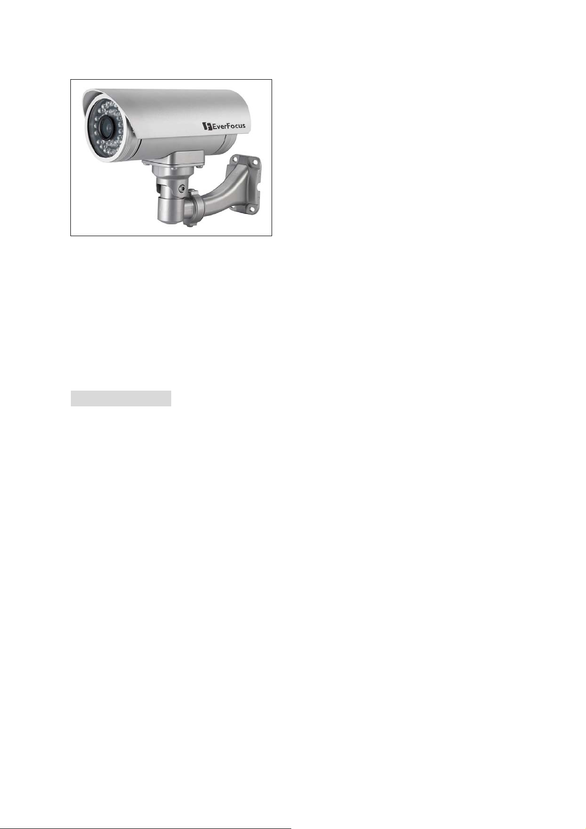
Weatherproof Long Range IR Camera
Operation Instructions
Model No. EZ230E/235E/330E/335E
Please read this manual first for correct installation and operation. This manual should be retained
for future reference. The information in this manual was current when published. The
manufacturer reserves the right to revise and improve its products. All specifications are therefore
subject to change without notice.
PRECAUTIONS
1. Do not place any object on top of the cover.
2. Be careful when handling the camera, do not drop it or subject it to strong shock or vibration
to prevent any damages to it. Do not disassemble it or place it on an unstable base.
3. Install the camera away from TV, radio transmitter, magnet, electric motor, transformer,
audio speakers because the magnetic fields generate from above devices will distort the
video image.
4. Install the camera away from stoves, or other heat generating devices as the high temperature
could cause deformation, discoloration or other damages of the camera. Install the camera
at where the temperature range will stay between -40℃ to 50℃ (-40℉ to 122℉).
5. Never aim the camera at the sun or other extremely bright objects whether it is in use or not.
6. Do not touch the surface of CCD sensor by hand directly. Use a soft cloth to remove the
dirt from the camera body. Use lens tissue or a cotton tipped applicator and ethanol to clean
the CCD sensor and the camera lens. When the camera is not in use, put the cover cap on
the lens mount.
7. All warnings on the products and in the operating instructions should be adhered to.
8. Do not use attachments not recommended by the appliance manufacturer as they may cause
hazards.
9. Do not allow anything to rest on the power cord. Do not locate this appliance where the cord
Page 2

will be abused by persons walking on it.
10. Do not overload wall outlets and extension cords as this can result in fire or electric shock.
11. Never push objects of any kind into his appliance through cabinet slots as they may touch
dangerous voltage points or short out parts that could result in fire or electric shock.
12. Refer all work related to the installation of this product to qualified service personnel or
system installers.
1
Page 3

PREFACE
EZ230E/235E/330E/335E series camera is a true day/night, weather-proof, long range IR color
camera, designed with the 1/3” SONY HAD color CCD to provide a high performance in low
LUX environment. It is ideal for outdoor applications such as parking lots, gas stations and
shopping malls.
FEATURES
z The electronic shutter and AGC functions allow the camera to be used in environment
with varying light levels
z The advanced 1/3” SONY Super HAD color CCD provides low light sensitivity 0.3
Lux/F=1.2 (AGC ON) for EZ230E/EZ235E and 0.4 Lux/F=1.2 (AGC ON) for EZ330E/335E
z Vari-frequency IR control
z Long IR distance: 30 meters/98 feet for EZ230E/EZ330E and 50 meters/164 feet for
EZ235E/EZ335E
z Lifespan of High Light IR LED is 20,000 hours
z IP66 weatherproof rated
z Built-in heater for camera to work in low temperature environment
z Cables covered by the bracket, to prevent from intentional destruction
z Internal cable connection provides installation without additional waterproof connection box
z Vandal proof design
2
Page 4

ST ANDARD ACCESSORIES
¾ IR Long Range Camera x 1
¾ Operation Instructions x 1 (this document)
¾ Waterproof Connector x 1 (connected to the camera body)
¾ Bracket x 1
¾ Mounting kit includes:
-Long Screws x 4 (for mounting bracket)
-Short Screws x 4 (for connecting camera body to bracket)
-Expanding Screws x 4
-Hex key x 1 (for adjusting bracket)
-Hexagon wrench x 1 (for adjusting sunshield)
3
Page 5
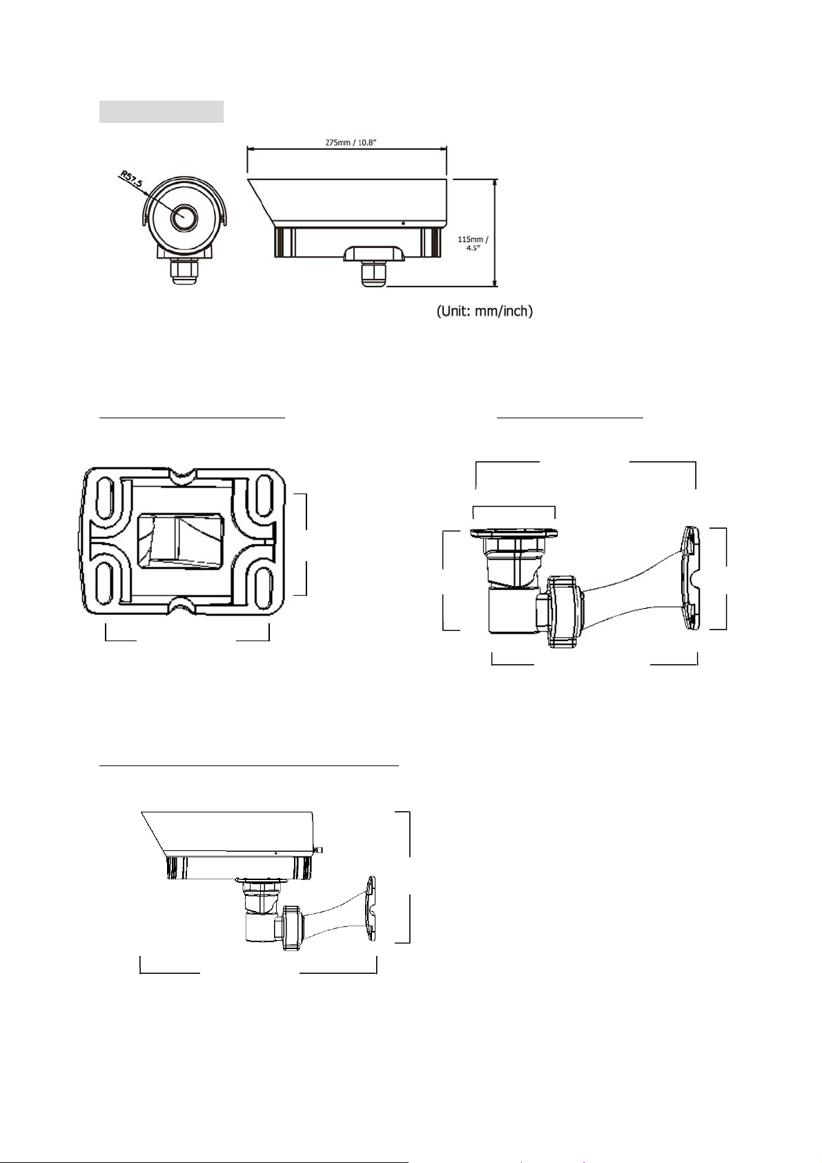
DIMENSIONS
Dimension of holes to holes Dimension of Bracket
45mm/1.8”
80mm/3.2”
The dimension of whole camera with bracket
95mm/3.8”
217mm/8.68”
215mm/8.6”
84mm/3.36”
100mm/4”
196mm/7.84”
350mm/14”
4
Page 6

NAMES AND FUNCTIONS OF BACK PANEL
24VAC model
1
○
○2
○
1
110V~240VAC model
○
2
○
3
○
3
1
○
Video Output Connector
Connect the video output of the camera to a color monitor or other video devices through a 75
Ohm type coaxial cable with BNC female connector at backside of the camera.
2
○
Power Input Terminal
Connect to the appropriate power to each model. N/L is used to connect to power in. PE is a
ground pin.
3
○
Cable clips
Used to fix power cable.
5
Page 7

INSTALLATION GUIDE
Sun shield
Fixing screw for sunshield
Bracket
Power connector
Video output
6
Page 8

1. Wire coaxial cable and power cable through the bracket.
Note: Please use RG59/5C2V coaxial cable without connector
2. Fix the bracket to wall by using 4 screws.
7
Page 9

3. Open camera’s back cover: Loose the 2 screws from the back panel, then open the back cover.
d
Screws for back panel
4. Take off the cap of waterproof connector which is under the camera.
Power cable
Coaxial cable Reserve
8
Page 10

Note: 1. The holes of waterproof connector were plugged by stoppers, please remove the
stoppers when you need to use it for connection.
2. Please always keep the smallest hole (5 mm) plugged by stopper, to avoid any possible
damage caused by humidity. This is a reserved hole.
5. Take coaxial cable and power cable to pass through waterproof connector, place them into
camera housing.
Note: Do not connect BNC connector to coaxial cable until coaxial cable has passed through
camera housing
9
Page 11

Video cable and power
cable
Note: 1. Power cable’s diameter must be under 10mm
2. Only use RG59/5C2V coaxial cable
6. Close the waterproof cap and fix waterproof connector to the base of camera firmly.
10
Page 12

7. Fix the camera body to bracket by using the 4 shorter screws.
8. Connect RG59 coaxial cable with BNC connector.
9. Unscrew the cable clips, wire power cable through the cable clips. Then, screw the cable
clips to rear panel.
Power cable
Coaxial cable
Cable Clips
11
Page 13

10. Close the back cover and screw the 2 screws firmly. Now, you are done with the installation.
Screws for back panel
ADJUSTMENT
Adjust camera’s angle vertically or horizontally by using hex key included in package.
Loose this screw to make
angle adjustment vertically
Loose this screw to make
angle adjustment horizontally
12
Page 14

SPECIFICATIONS
Type
Pickup Device
Picture Elements
Horizontal Resolution
Video Output
*Lens Type
Sensitivity
Gamma Correction
S/N Ratio
Auto White Balance
Black Light Comp.
Auto Gain Control
Sync. Mode
EZ230E EZ235E EZ330E EZ335E
1/3” SONY Super HAD CCD
510 x 492 (NTSC) 768 x 494 (NTSC)
500 x 582 (PAL) 752 x 582 (PAL)
380 TVL 520 TVL
BNC 1.0Vp-p, 75ohm
6mm, 8mm 8mm, 16mm, 25mm 6mm, 8mm 8mm, 16mm, 25mm
0.3 Lux/F=1.2 (AGC ON)
0.4 Lux/F=1.2 (AGC ON)
0 Lux (IR On) 0 Lux (IR On)
0.45
Over 48 dB (AGC off)
Yes
Yes
Yes
Internal Sync.
IR LED Lifespan
20,000 hours
Weatherproof
Power Source
Power Consumption
Dimensions
Operating
115mm(W) x 115mm(H) x 275mm(D) ; 4.5"(W) x 4.5" (H) x 10.8"(D)
-40°C to +50°C ; -40℉ to 122℉ (20%~80% Humidity)
2 types: 24VAC ; 100VAC~240VAC
24VAC / 100VAC~240VAC : 16W max.
Temperature
Weight
IR Distance
30M / 98 feet 50M / 164 feet 30M / 98 feet 50M / 164 feet
2.5 kg ; 5.5 lbs (with bracket)
IR Wavelength
Certifications
FCC/CE
*Lens models and availability vary in different regions
IP66
850nm
13
Page 15

Y
EverFocus Electronics Corp.
Head Office:
12F, No.79 Sec. 1 Shin-Tai Wu Road,
Hsi-Chih, T aipei, Taiwan
TEL: +886-2-26982334
FAX: +886-2-26982380
www.everfocus.com.tw
USA L.A. Office:
1801 Highland Ave. Unit A
Duarte, CA 91010, U.S.A.
TEL: +1-626-844-8888
FAX: +1-626-844-8838
www.everfocus.com
USA N.Y. Office:
415 Oser Avenue Unit S
Hauppauge, NY 11788
TEL: 631-436-5070
FAX: 631-436-5027
www.everfocus.com
Europe Office:
Albert-Einstein-Strasse 1
D-46446 Emmerich, Germany
TEL: 49-2822-9394-0
www.everfocus.de
China Office:
Room 609, Technology Trade Building,
Shangdi Information Industry Base, Haidian
District, Beijing,China 10085
TEL: +86-10-62973336/37/38/39
FAX: +86-10-62971423
www.everfocus.com.cn
Japan Office:
1809 WBG MARIBU East 18F,
2-6 Nakase.Mihama-ku.
Chiba city 261-7118, Japan
TEL: +81-43-212-8188
FAX: +81-43-297-0081
www.everfocus.com
our EverFocus product is designed and
manufactured with high quality materials and
components which can be recycled and
reused.
This symbol means that electrical and
electronic equipment, at their end-of-life,
should be disposed of separately from your
household waste.
Please, dispose of this equipment at your
local community waste collection/recycling
centre.
In the European Union there are separate
collection systems for used electrical and
electronic product.
Please, help us to conserve the environment
we live in!
Ihr EverFocus Produkt wurde entwickelt und
hergestellt mit qualitativ hochwertigen
Materialien und Komponenten, die recycelt
und wieder verwendet werden können.
Dieses Symbol bedeutet, dass elektrische und
elektronische Geräte am Ende ihrer
Nutzungsdauer vom Hausmüll getrennt
entsorgt werden sollen.
Bitte entsorgen Sie dieses Gerät bei Ihrer
örtlichen kommunalen Sammelstelle oder im
Recycling Centre.
Helfen Sie uns bitte, die Umwelt zu erhalten, in
!
der wir leben
P/N: MZ23G00210_Ver.D
14
 Loading...