

Page 1
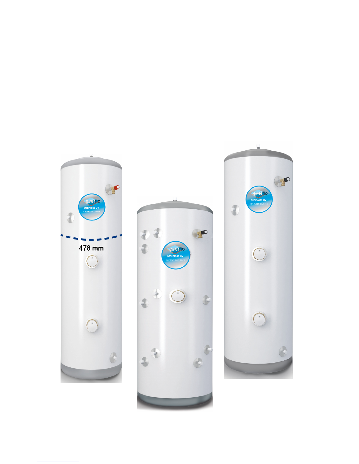
EVERFLO STAINLESS UV
UNVENTED HOT WATER CYLINDERS
INSTALLATION AND MAINTENANCE INSTRUCTIONS
ISSUE 3 MAY 2015
Page 2

01
EVERFLO STAINLESS UV
UNVENTED HOT WATER CYLINDERS
PAGE CONTENT
2 Introduction
3 Storage, Handling & Supply Requirements
3 Component Table
4 Sitting the unit
5 General Installation
7-8 Discharge Arrangement
9 Technical Specications: Slimline - Direct & Indirect
10 Technical Specications: Direct & Indirect
11 Technical Specications: Solar Direct
12 Technical Specications: Solar Indirect
13 Solar Coil Installation
4 Solar High Limit
15 S-Plan Wiring Schematics
16 Y-Plan Wiring Schematics
17 - 18 Pre-Plumbed Wiring Schematics
19 Pre-Plumbed Installation
20 Technical Specications: Pre-Plumbed
21 System Fit Installation
22 Technical Specications: System Fit
23 Commissioning & Servicing
24 Fault Finding & User Instructions
25 - 27 Guarantee - Terms & Conditions
28 Technical Specication
29 - 30 Specication & Performance
31 Benchmark
32 Commissioning Check Sheet
33 Service Record
INTRODUCTION
The EVERFLO STAINLESS UV Unvented cylinder is made from
Duplex Stainless Steel for excellent corrosion resistance.
EVERFLO STAINLESS UV has a strong rust-proofed steel case
and is highly insulated with environmentally friendly foam.
EVERFLO STAINLESS UV is supplied complete with all the
necessary safety and control devices needed to connect
to the cold water mains. All are pre-adjusted. High quality
controls have been selected to combine high ow rate
performance with minimum pressure drop to make EVERFLO
STAINLESS UV perform well in all areas, even those with poor
water pressure.
EVERFLO STAINLESS UV is KIWA approved to show
compliance with Building Regulations G3+L.
Benchmark p laces responsibilities on both manufacturers and installers . The
purpose is to ensure that customers are p rovided with the correct equipment
for their ne eds, that it is installed, commissioned and ser viced in accordance
with the manufacturer’s instructions by competent persons and that it meets
the require ments of the appropriate Building R egulations. The Benchmark
Checklis t can be used to demonstrate compliance with Building Regulations
and should b e provided to the custome r for future reference.
Installers are required to carr y out installation, com missioning and servicing
work in accordance with the Benchmark Code of Practice which is available
from the Heating and Hot water Industry Council who mana ge and promote
the Scheme. Visit ww w.centralheating.co.uk for more info rmation.
IMPORTANT NOTE TO
THE INSTALLER
Read these instructions before commencing installation.
Unvented cylinders are a controlled service as dened in the
latest edition of the building regulations and should only be
tted by a competent person.
The relevant regulations are: England and Wales – Building
Regulation G3, Scotland – Technical Standard P3, N Ireland –
Building Regulation Part F
After installation the Benchmark check list must be
completed and left, with these instructions, with the
householder for future reference.
IMPORTANT NOTE TO THE INSTALLER
Read these instructions before commencing installation. Unvented cylinders are a controlled service
as dened in the latest edition of the building regulations and should only be tted by a competent
person.
The relevant regulations are: England and Wales – Building Regulation G3, Scotland – Technical Standard
P3, N Ireland – Building Regulation Part F
After installation the Benchmark check list must be completed and left, with these instructions, with
the householder for future reference.
Page 3
02
EVERFLO STAINLESS UV
UNVENTED HOT WATER CYLINDERS
STORAGE PRIOR TO INSTALLATION
EVERFLO STAINLESS UV should be stored in its original packaging
in an upright position in an area free from excessive damp.
Regulations G3+L.
HANDLING PRODUCT
The EVERFLO STAINLESS UV should be carried upright where
possible. Assessments of risks for carrying the cylinder should
be conducted. Use more than 1 person for carrying where
appropriate. Always follow latest guide lines for lifting techniques,
to avoid injury and damage to the product.
WATER SUPPLY
EVERFLO STAINLESS UV operates at 3 bar (controlled by the inlet
control set) and is capable of delivering over 50 litres per minute.
The high quality inlet control set has been designed to make the
most of the ow rates available, however the performance of any
unvented system is only as good as the mains water supply. The
maximum possible water demand should be assessed, taking
into consideration that both hot and cold services are supplied
simultaneously from the mains.
The water supply should be checked to ensure it can meet these
requirements. If necessary, consult the local water company
regarding the likely pressure and ow rate availability.
If measuring the water pressure, note that a high static (no ow)
mains pressure is no guarantee of good ow availability. In a
domestic installation 1.5 bar and 25 l/min. should be regarded as
the minimum. The maximum mains pressure that the inlet control
set can accept is 12 bar.
Consideration should be given to upgrading existing ½” (15mm)
cold mains pipework to a larger size if the recommended
minimum pressure/ow rate is not being achieved.
ELECTRIC SUPPLY
The EVERFLO STAINLESS UV requires 240 Volt electrical supply for
the standard Incoloy immersion elements. The electrical supply
to each immersion heater must be fused at 13A via a double
pole isolating switch to BS 3456. The cable must be at least
2.5mm2 heat resistant (85°C HOFR) sheathed ex complying to BS
6141:1981 Table 8.
UNPACKING THE UNIT
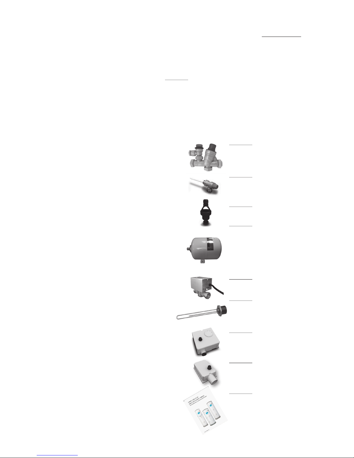
EVERFLO STAINLESS UV comes complete with the ttings required
to complete the installation. Please see over for component
content list.
High ow rate inlet control set
TS201-533
Temperature and pressure relief valve
TS202
Acetal tundish 15 x 22 mm
TS3
Incoloy long life
3 kW immersion heater
TS9 - DIRECT TS10 - INDIRECT
Two port valve
TS5
Dual thermostat
US201
High Limit thermostat
TS28
Installation &
Maintenance Instructions
Expansion Vessel
• 60, 90, 120 & 150 ltr units - 12 ltr vessel TS212
• 180, 210 & 250 ltr units - 18 ltr vessel TS219
• 300 ltr units - 25 ltr vessel
TS224
Page 4

03
EVERFLO STAINLESS UV
UNVENTED HOT WATER CYLINDERS
COMPONENT CONTENT TABLE
Inlet Control set • • • • • • • • • •
Temp & Pressure relief valve
• • • • • • • • • •
Tundish
• • • • • • • • • •
Expansion vessel
• • • • • • • • • •
Immersion Heater (Direct)
• • •
Immersion Heater (Indirect)
• • • • • • •
Two Port Valve
• • • • • • •
Dual Thermostat
• • • • • • •
Single High Limit Stat
• • • • • •
Sensor pocket retaining bungs
• • • •
Robo-Kit
• • • •
TP9000
• • • •
TP5000
• •
Installation & Maintenance
Instructions
• • • • • • • • • •
Slimline Direct Models (Electric)
Slimline Indirect Models
Direct Models
Indirect Models
Solar Direct Models
Solar Indiect Models
Indirect pre-plumbed
models - 1 zone heating
Indirect pre-plumbed
models - 2 zone heating
Solar indirect pre-plumbed models - 1
zone heating
Solar indirect pre-plumbed models - 2
zone heating
Direct M odels (Elect ric)
Direct S olar Models (Ele ctric + Coil)
Indirec t Models (Single Co il)
Indirec t Solar Models ( Twin Coil)
Page 5
04
EVERFLO STAINLESS UV
UNVENTED HOT WATER CYLINDERS
SITTING THE UNIT
EVERFLO STAINLESS UV can supply outlets above it or at some
distance from it. Site the unit to minimise “dead leg” distances,
especially to the point of most frequent use.
Outlets above the EVERFLO STAINLESS UV will reduce the outlet
pressure available by 0.1 bar for every 1m of height dierence. The
unit should be protected from frost. Particular care is needed if
sitting in a garage or outbuilding. All exposed pipework should be
insulated. EVERFLO STAINLESS UV must be installed VERTICALLY
on a at base capable of supporting the weight of the cylinder
when full. See technical specication section (page 27-28) for
weights. The minimum recommended cupboard size is 650mm
square.
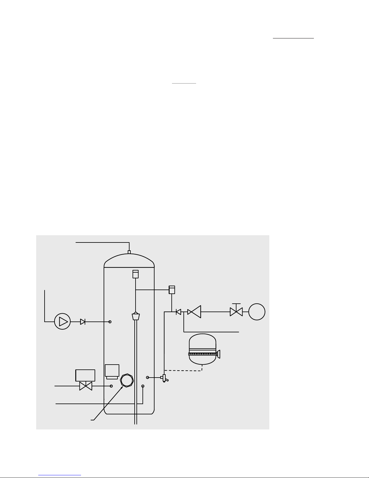
NOTES:
The pressure reducing
valve, non-return valve and
expansion relief valve are
combined together in the
inlet control set.
On 60 – 180 litre sizes there
is no dedicated secondar y
return boss and the
secondary return circuit
should be tee’d into the cold
feed pipe just above the
drain elbow.
SCHEMATIC DIAGRAM
Access for maintenance of the valves should be considered.
Consideration should be given to position of discharge pipes
(tundish), drain valves - shall be positioned away from electrical
components.
The immersion heaters are 375mm long and care should be taken
to ensure that they can be withdrawn for servicing if required.
The discharge pipework from the safety valves should fall
continuously and terminate safely.
IMMERSION
HEATER
COLD
MAIN
ISOLATING
VALVE
PRESSURE
REDUCING
VALVE
NON
RETURN
VALVE
EXPANSION
RELIEF
VALVE
TUNDISH
TEMPERATURE
& PRESSURE
RELIEF VALVE
BALANCED
COLD
CONNECTION
COLD
INLET VIA
DRAIN
NON
RETURN
VALVE
BRONZE
PUMP
SECONDARY RETURN CIRCUIT
( 210, 250 & 300 L SIZES )
DUAL
STAT
2 PORT
VALVE
BOILER
FLOW
BOILER
RETURN
HOT OUTLET
EXPANSION
VESSEL
WITH WALL
BRACKET
Page 6
05
EVERFLO UNVENTED HOT WATER CYLINDERS
GENERAL INSTALLATION
COLD MAINS PIPEWORK
Run the cold main through the building to the place where the
EVERFLO STAINLESS UV is to be installed. Take care not to run the
cold pipe near hot water or heating pipework so that the heat
pick-up is minimized. Identify the cold water supply pipe and t
an isolating valve (not supplied).
A 22mm BS1010 stopcock can typically be used but a 22mm
quarter turn full bore valve would be better as it does not
restrict the ow as much. Do not use “screwdriver slot” or similar
valves. Make the connection to the cold feed of the cylinder
and incorporate a drain valve. Position the drain valve no higher
than the cold inlet to ensure sucient draining of cylinder when
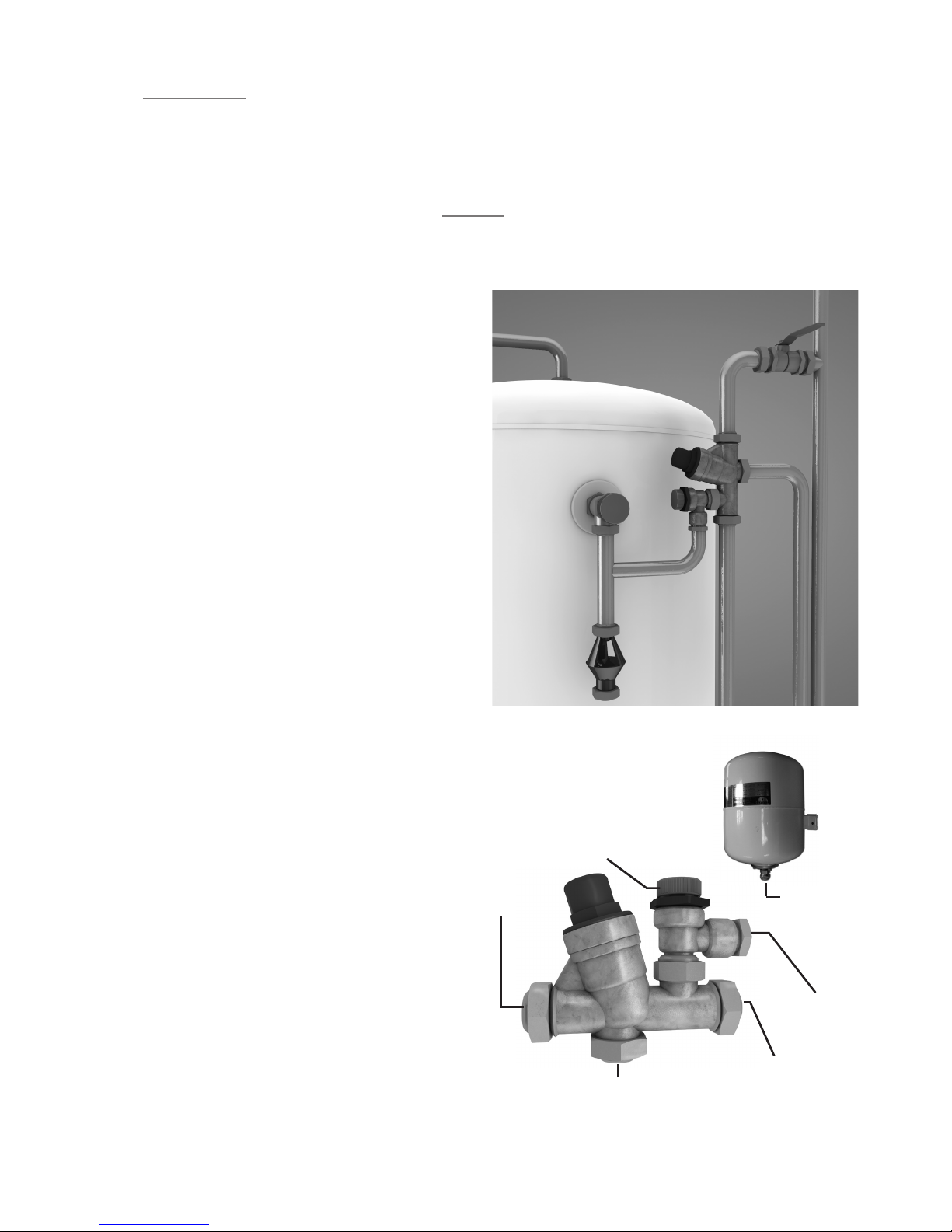
required. Position the inlet control just ABOVE the Temperature &
Pressure Relief Valve (TPRV) mounted on the side of the cylinder.
This ensures that the cylinder does not have to be drained down
in order to service the inlet control set. Ensure that the arrow
points in the direction of the water ow. Select a suitable position
for the expansion vessel. Mount it to the wall using the bracket
attached to the vessel. Use suitable ttings capable of supporting
full vessel weight (and with appropriate consideration to wall
material). Ensure the pre-charge in the vessel is set at 3 Bar.
Connect the expansion vessel to the cold feed pipework between
the inlet control set and the cold inlet on the cylinder. Ensure that
the top of the vessel is accessible for servicing.
CONNECTING TO THE CYLINDER
All of the pipework connections on the cylinder are 22mm
compression and supplied complete with gland nuts and olives, in
the Accessory Kit box. Only connect 22mm Table X copper tube to
these connections.
Cut the tube with a pipe cutter and ensure no sharp edges or
burrs protrude. Slide both gland nut and olive onto the tube and
push tube fully home into the connection, ensuring the tube
end fully bottoms on the connection recess. Smear the outer
wall of the olive with plumbing paste and tighten gland nut
in the prescribed manner. Upon lling/commissioning, ensure
all connections are completely watertight. Note: No control or
isolation valve should be tted between the expansion relief valve
and the storage cylinder. The relief valve connections should not
be used for any other purpose.
(expansion vessel not to scale)
Turn to
test
Cold
Mains In
Balanced Cold
Connection
Outlet to Cylinder
Expansion
Relief to
Tundish
Expansion
Relief
Connection
Page 7

06
EVERFLO STAINLESS UV
UNVENTED HOT WATER CYLINDERS
BALANCED COLD CONNECTION
If there are to be showers, bidets or monobloc taps in the
installation then a balanced cold supply is necessary. There is a
22mm balanced connection on the inlet set.
HOT WATER PIPEWORK
Run the rst part of the hot water distribution pipework in 22mm.
This can be reduced to 15mm and 10mm as appropriate for the
type of tap etc. Your aim should be to reduce the volume of the
hot draw-o pipework to a practical minimum so that the time
taken for the hot water is as quick as possible. Where monobloc
mixing taps and showers are used, these should be installed to
comply with the Water Supply (Water Fittings) Regulations 1999.
If these devices are supplied with un-balanced supplies there
should be single check valves installed at both inlets, to stop over
pressurising of either supply.
PRIMARY COIL CONNECTIONS FOR INDIRECT UNITS
For Solar input models refer to pages 13-14 before making any
connections.
Connect the primary connections (Indirect only) using the
compression connections provided. The primary circuit must
be positively pumped. Gravity circulation is not suitable. Either
primary connection may be used as the primary ow, reheat times
are not eected. The primary circuit can be open vented or sealed,
with up to a maximum pressure of 3.5 bar. If you seal the primary
circuit an additional expansion vessel and safety valve is required.
The boiler may be Gas, Electric or Oil but must be under eective
thermostatic control. Uncontrolled heat sources such as some
AGA’s, back boilers, solid fuel stoves, etc. are NOT SUITABLE. Please
contact our Technical department for guidance. Connect the two
port zone valve ( indirect only ) into the primary ow pipework.
The direction of ow arrow should be towards the primary ow
connection.
SECONDARY CIRCULATION
EVERFLO STAINLESS UV can be used with secondary circulation.
An appropriate WRAS approved bronze circulator should be
used in conjunction with a non-return valve to prevent backow.
On large secondary circulation systems it may be necessary
to incorporate an extra expansion vessel into the circuit to
accommodate the increased system water volume. Secondary
circulation should be avoided on Direct electrically heated units
being used on o-peak electricity taris.
A secondary return boss is tted as standard on 210, 250 & 300 ltr
units. On smaller sizes, tee into the cold feed pipe above the drain.
IMMERSION HEATERS
Only immersion heaters with a thermal cut-out may be used. To
help ensure this, the immersion heaters have a special 1¾” thread.
They are rated at 3kW at 240V and are of a low noise Incoloy
construction.
They have both a thermostat and a high limit cutout. Please order
the correct replacement via ourselves; tting non-approved
immersions may aect your guarantee. When tting, ensure the
‘O’ ring is positioned correctly on the head of the immersion
heater and lubricate before tting. Fit it by hand until almost
home then tighten gently as the ‘O’ rings will seal easily. The
electrical supply to each immersion heater must be fused at 13A
via a double pole isolating switch to BS 3456. The cable must be
2.5mm
2
heat resistant (85°C HOFR) sheathed ex complying to BS
6141:1981 Table 8. Do not operate the immersion heater/s until the
unit is full of water. Do not operate the immersion heater/s if any
sterilisation liquid is in the cylinder as this will cause premature
failure.
ELECTRICAL CONNECTIONS
Complete the wiring – use the appropriate wiring diagrams on
page 15 - 18.
Page 8
07
EVERFLO STAINLESS UV
UNVENTED HOT WATER CYLINDERS
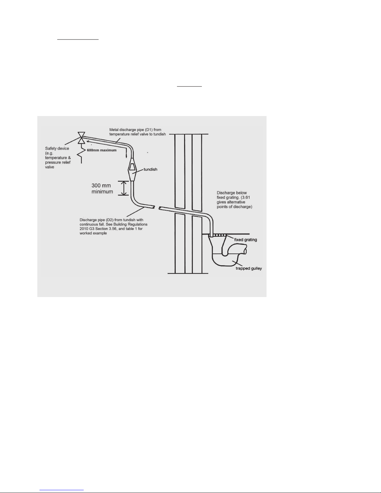
DISCHARGE ARRANGEMENT
Position the inlet control group so that the discharge from both
safety valves can be joined together via a 15mm end feed Tee (see
diagram above). Connect the Tundish and route the discharge
pipe. The discharge pipework must be routed in accordance with
Part G3 of schedule 1 of the Building Regulations. The information
that follows is not exhaustive and if you are in doubt you should
seek advice. The two safety valves will only discharge water under
fault conditions. When operating normally water will not be
discharged. The tundish should be vertical, located in the same
space as the unvented hot water storage system and be tted
as close as possible to, and lower than, the safety device, with
no more than 600mm of pipe between the valve outlet and the
tundish. The tundish should be positioned away from electrical
devices.
Any Discharge should be visible at the tundish. The tundish should
be located such that any discharge is visible. In addition, where
discharges from safety devices may not be apparent, e.g. people
with impaired vision or mobility, consideration should be given to
the installation of a suitable safety device to warn when discharge
takes place, e.g. electronically operated.
Diagram of a typical discharge pipe arrangement (extract from
Building Regulation G3)
Note: The discharge will consist
of scalding water and steam.
Asphalt, roong felt and
non-metallic rainwater goods
may be damaged by such
discharges.
Note: D2 pipe from tundish is
now allowed to be installed in
soil stacks within premises. This
activity is not recommended
by Kingspan as discharge
from T&P may continue for
long periods of time. It is the
installer’s responsibility to
ensure the discharge pipework
can support the discharge for
prolonged periods.
If used follow guidance on
mechanical seal without water
trap given in G3 Building
Regulations.
As discharge can be in
excess of 90
o
C discharge into
plastic pipework is also not
recommended.
Page 9

08
EVERFLO STAINLESS UV
UNVENTED HOT WATER CYLINDERS
The discharge pipe (D2) from the tundish should:
A) Have a vertical section of pipe at least 300mm long, below the
tundish before any elbows or bends in the pipework.
B) Be installed with a continuous fall of at least 1 in 200 thereafter.
The discharge pipe (D2) from the tundish should be of metal or
other material that have been demonstrated to be capable of
withstanding temperatures of the water discharged.
The discharge pipe (D2) should be at least one pipe size larger
than the nominal outlet size of the safety device unless its total
equivalent hydraulic resistance exceeds that of a straight pipe
9m long i.e. discharge pipes between 9m and 18m equivalent
resistance length should be at least two sizes larger than the
nominal outlet size of the safety device, between 18 and 27m at
least 3 sizes larger, and so on. Bends must be taken into account
in calculating the ow resistance. Refer to diagram 1, Table 1 and
the worked example. An alternative approach for sizing discharge
pipes would be to follow BS6700 Specication for design
installation, testing and maintenance of services supplying water
for domestic use within buildings and their curtilages.
The discharge pipe (D2) should terminate in a safe place where
there is no risk to persons in the vicinity of the discharge.
Examples of acceptable discharge arrangements are:
a. To a trapped gully with the end of the pipe below the xed
grating and above the water seal.
b. Downward discharges at a low level; i.e. up to 100mm above
external surfaces such as car parks, hard standings, grassed
areas etc. are acceptable providing that where children play or
otherwise come into contact with discharges, a wire cage or
similar guard is positioned to prevent contact whilst maintaining
visibility.
c. Discharges at a high level; e.g. in to metal hopper and metal
down pipe with the end of the discharge pipe clearly visible or
onto a roof capable of withstanding high temperature discharges
of water and 3m from any plastic guttering systems that would
collect such discharges.
d. Device to warn when discharge takes place.
WORKED EXAMPLE
The example below is for G1/2 temperature relief valve with a
discharge pipe (D2) having 4 No. elbows and length of 7m from
the tundish to the point of discharge.
From Table 1:
Maximum resistance allowed for a straight length of 22mm
copper discharge pipe (D2) from a G1/2 temperature relief valve is:
9.0m. Subtract the resistance for 4 No. 22mm elbows at 0.8m each
= 3.2m. Therefore the maximum permitted length equates to:
5.8m. 5.8m is less than the actual length of 7m therefore calculate
the next largest size. Maximum resistance allowed for a straight
length of 28mm pipe (D2) from a G1/2 temperature relief valve
equates to: 14m. As the actual length is 7m, a 28mm (D2) copper
pipe will be satisfactory.
TABLE 1
Sizing of copper discharge pipe ‘D2’ for a temperature
relief valve with a G1/2 outlet size (as supplied).
Size of
discharge
pipework
Maximum length of
straight pipe
(no bends or elbows)
Deduct the gure below
from the maximum length
for each bend or elbow in the
discharge pipe
22mm Up to 9m 0.8m
28mm Up to 18m 1m
35mm Up to 27m 1.4m
Page 10
09
EVERFLO STAINLESS UV
UNVENTED HOT WATER CYLINDERS
EVERFLO STAINLESS UV
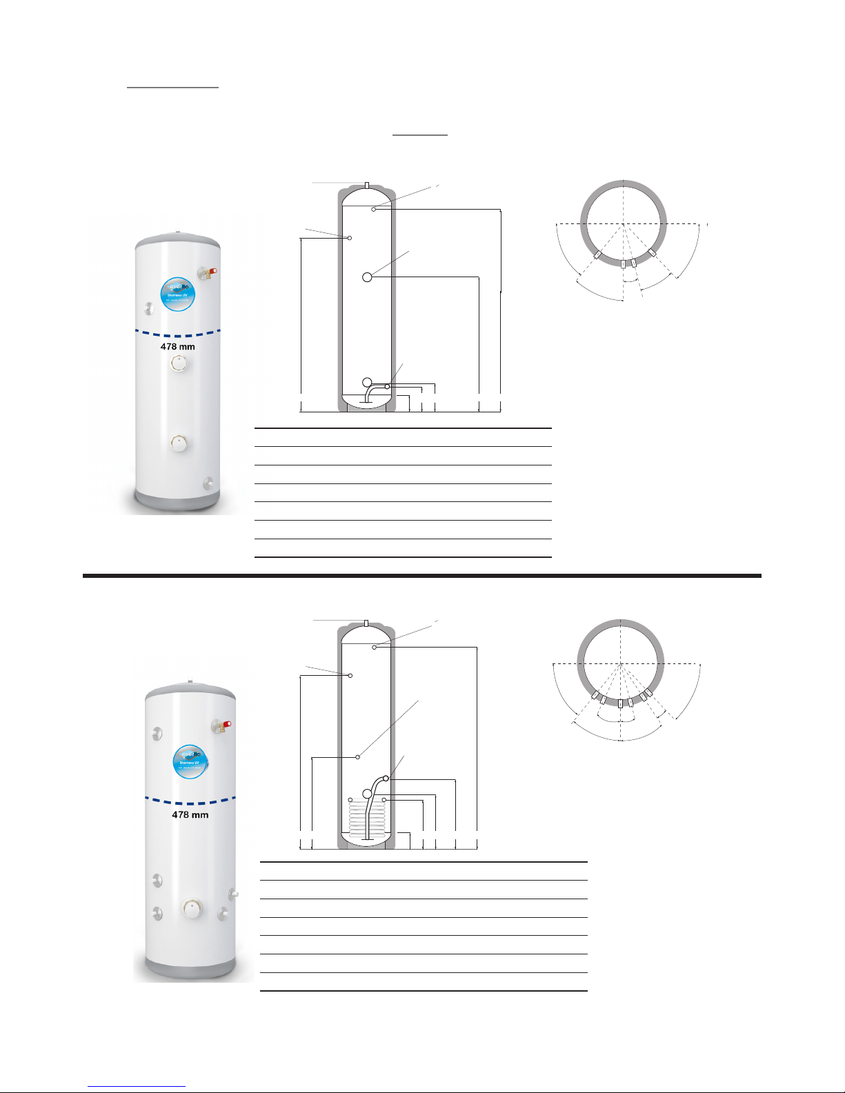
SLIMLINE DIRECT
EVERFLO STAINLESS UV
SLIMLINE INDIRECT
B
A
120.00
“
F PTRV BOSS
1
2
D A B
C G
F D A B C G
22mm HOT
DRAW - OFF
22mm SECONDARY
RETURN (not always tted.
See table)
22mm COLD FEED WITH
DIP PIPE TO DEFLECTOR
IN BOTTOM OF CYLINDER
22mm HOT
DRAW - OFF
22mm SECONDARY
RETURN (not always tted.
See table)
“
F PTRV BOSS
1
2
22mm COLD FEED WITH
DRY STAT POCKET
DIP PIPE TO DEFLECTOR
IN BOTTOM OF CYLINDER
120.00
SECOND IMMERSION HEATER
(not always tted. See table)
25.0˚
40.0˚
45.0˚
35.0˚
15.0˚
40.0˚
45.0˚
15.0˚
B
A
120.00
“
F PTRV BOSS
1
2
D A B
C G F D A B C G
22mm HOT
DRAW - OFF
22mm SECONDARY
RETURN (not always tted.
See table)
22mm COLD FEED WITH
DIP PIPE TO DEFLECTOR
IN BOTTOM OF CYLINDER
22mm HOT
DRAW - OFF
22mm SECONDARY
RETURN (not always tted.
See table)
“
F PTRV BOSS
1
2
22mm COLD FEED WITH
DRY STAT POCKET
DIP PIPE TO DEFLECTOR
IN BOTTOM OF CYLINDER
120.00
SECOND IMMERSION HEATER
(not always tted. See table)
30.0˚
50.0˚
50.0˚
10.0˚
25.0˚
40.0˚
45.0˚
35.0˚
15.0˚
“
F PTRV BOSS
1
2
22mm COLD FEED WITH
DRY STAT POCKET
DIP PIPE TO DEFLECTOR
IN BOTTOM OF CYLINDER
120.00
50.0˚
10.0˚
CODE H EIGHT D IAMETER A B C D G
EDS60 673 478 175 210 N/F N/F 483
EDS90 1048 478 175 210 610 N/ F 858
EDS120 1236 478 175 210 710 N /F 1046
EDS150 1424 478 175 210 810 N /F 1234
EDS180 1674 478 175 210 910 N /F 1484
EDS210 1987 478 175 210 1100 1500 1797
F D A B C G
22mm HOT
DRAW - OFF
22mm SECONDARY
RETURN (not always tted.
See table)
“
F PTRV BOSS
1
2
22mm COLD FEED WITH
DRY STAT POCKET
DIP PIPE TO DEFLECTOR
IN BOTTOM OF CYLINDER
120.00
CODE HEI GHT DIAME TER A B C D F G
ENS60 673 478 3 40 38 0 44 0 395 N/F 483
ENS90 104 8 478 340 380 4 40 39 5 N /F 858
ENS120 1236 478 340 38 0 4 40 395 N/F 1046
ENS150 1424 478 380 420 520 520 N/F 1234
ENS180 1674 478 380 420 520 610 N/F 1484
ENS210 1987 478 380 420 520 710 1500 1797
TECHNICAL SPECIFICATIONS
Page 11
10
EVERFLO STAINLESS UV
UNVENTED HOT WATER CYLINDERS
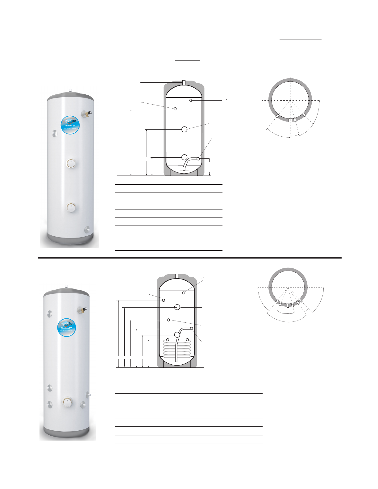
EVERFLO STAINLESS UV DIRECT
EVERFLO STAINLESS UV INDIRECT
25.0˚
40.0˚
45.0˚
35.0˚
15.0˚
“
F PTRV BOSS
1
2
22mm COLD FEED WITH
DRY STAT POCKET
DIP PIPE TO DEFLECTOR
IN BOTTOM OF CYLINDER
120.00
50.0˚
10.0˚
15.0
0
25.0
0
30.0
0
45.0
0
160mm
195mm
FD
22mm HOT
DRAW - OFF
“
F PTRV BOSS
22mm SECONDARY
RETURN (not always tted.
See table)
22mm COLD FEED WITH
DIP PIPE TO DEFLECTOR
IN BOTTOM OF CYLINDER
1
2
SECOND IMMERSION
HEATER (not always tted.
See table)
CODE HEI GHT DIAME TER D F
ED90 718 550 N /F N/ F
ED120 906 550 N /F 510
ED150 1093 550 N/F 610
ED180 1281 550 N/F 710
ED210 1469 550 1000 810
ED250 1719 550 1250 950
ED300 2032 550 1500 1100
22mm COLD FEED WITH
DIP PIPE TO DEFLECTOR
IN BOTTOM OF CYLINDER
22mm SECONDARY
RETURN (not always tted.
See table)
22mm HOT
DRAW - OFF
“
F PTRV BOSS
1
2
DRY STAT
POCKET
SECOND IMMERSION HEATER
(not always tted. See table)
F E D C B A
CODE HEIGHT D IAMETER A B C D E F
EN90 718 550 290 330 390 3 45 N /F N/F
EN120 906 550 2 90 33 0 39 0 34 5 N /F N/F
EN150 1093 550 330 370 465 385 N /F N/F
EN180 1281 550 330 370 46 5 385 N/F N/ F
EN210 1469 550 365 4 05 4 65 46 5 N/ F 1150
EN250 1719 550 365 4 05 4 65 56 0 950 1400
EN300 2032 550 365 4 05 4 65 66 0 1100 160 0
All Dimensions are in mm and
are of the cased unit.
N/F = not tted.
TECHNICAL SPECIFICATIONS
Page 12
11
EVERFLO STAINLESS UV
UNVENTED HOT WATER CYLINDERS
TECHNICAL SPECIFICATIONS
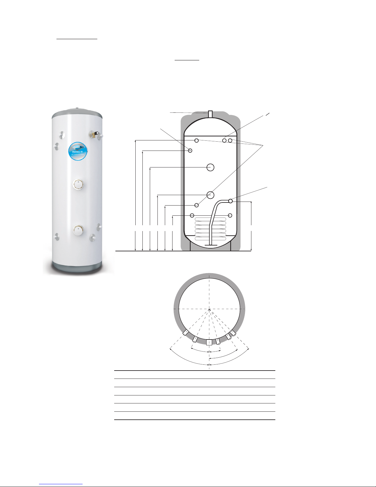
EVERFLO STAINLESS UV
SOLAR DIRECT
AB GCDEF
22mm HOT DRAW-OFF
22mm COLD FEED
WITH DIP PIPE
TO DEFLECTOR
IN BOTTOM
OF CYLINDER
“
F PTRV BOSS
1
2
DRY STAT
POCKET
25.0015.0
0
40.0
0
45.0
0
35.0
0
22mm SECONDARY
RETURN (not always fitted.
See table)
25.0015.0
0
40.0
0
45.0
0
35.0
0
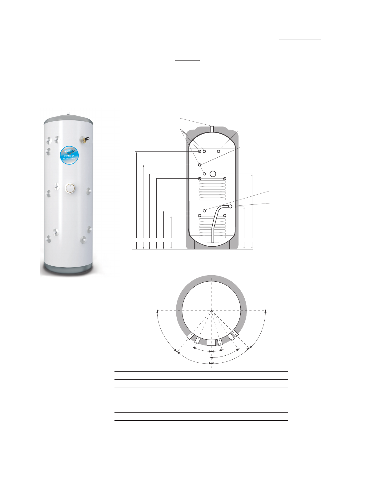
CODE HEI GHT DIA METER A B C D E F G
ESD150 1093 550 2 90 3 45 39 0 610 N/F 892 390
ESD180 1281 550 2 90 3 45 4 45 710 N/F 1080 39 0
ESD210 1469 550 3 65 420 500 810 1150 12 68 465
ESD250 1719 550 3 65 420 670 1045 1400 1519 465
ESD30 0 2032 550 36 5 420 670 1100 1600 1831 465
Page 13
12
EVERFLO STAINLESS UV
UNVENTED HOT WATER CYLINDERS
TECHNICAL SPECIFICATIONS
EVERFLO STAINLESS UV
SOLAR INDIRECT
All Dimensions are in mm and
are of the cased unit.
N/F = not tted.
25.0
0
15.0
0
40.0
0
45.0
0
35.0
0
DRY STAT
POCKET
DRY STAT
POCKET
22mm COLD
FEED WITH DIP PIPE
TO DEFLECTOR IN
BOTTOM OF CYLINDER
22mm SECONDARY RETURN
(not always tted. See table)
½” F PTRV BOSS
22mm HOT DRAW-OFF
EF D C B A G H
50.0
0
0
45.0
CODE H EIGHT D IAMETER A B C D E F G H
ET150 109 3 550 29 0 345 642 697 N/ F 892 390 693
ET180 1281 550 290 345 674 729 N /F 1080 390 7 25
ET210 146 9 550 365 420 779 83 4 1150 126 8 465 830
ET250 1719 550 365 420 950 1005 1400 1518 4 65 1000
ET300 20 32 550 365 420 979 1034 1600 1832 4 65 1030
Page 14

13
EVERFLO STAINLESS UV
UNVENTED HOT WATER CYLINDERS
EVERFLO SOLAR
UNVENTED
DIRECT SINGLE COIL CYLINDER
Detail for the installation of a Solar Unvented Direct cylinder.
GENERAL
When installing this product it is essential the overall installation
meets all current legislation including, in particular, the high limit
isolation requirements of Building Regulation G3. This document
is designed to assist in achieving that aim.
WATER
The potable water connection and tundish discharge connection
are to be connected in exactly the manner described in Pages 5 to
8 of this manual.
IMMERSION HEATERS
The standard issue immersion heaters are designed for domestic
usage where the lower heater is connected to a low rate o-peak
tari and the upper heater used for occasional top-up purposes.
Heaters of this nature are not designed to be permanently live.
Connect in accordance with instructions on page 6.
SOLAR CONNECTIONS
The ow and return from the solar heat source are to be
connected to the indirect coil. Either primary coil connection may
be utilised as the ow or return. The solar primary circuit must
have its own dedicated circulating pump, thermal and safety
controls which must be installed as per the solar manufacturers
instructions. The solar control system used must be of the solar
dierential control type and should be connected to the solar
sensor.
The solar sensor, supplied as part of the solar controls should be
inserts into Pocket B (page 11) and is held in-situ with the black
sensor pocket retaining bung provided.
It is necessary to connect the solar pump via the over-temperature
high limit cut-out (provided) to ensure the heat input to the solar
coil is interupted if the cylinder over heats. Some method to
prevent thermosyphoning must also be employed. Non-return
check valves in the primary ow and return pipework would be
acceptable.
If solar controls do not oer appropriate isolation a 2 port zone
valve (not supplied) can be used with the pump and high limit stat
as shown on pages 13 and 14.
INDIRECT TWIN COIL CYLINDER
UPPER COIL
The upper coil is connected to the fossil fuel boiler as per the
instructions for the EVERFLO STAINLESS UV Unvented Indirect
single coil model with the dual stat control and high limit
thermostat inserted into pocket D (diagram page 12). The wiring
requirements are as depicted on page 14.
LOWER COIL: SOLAR INSTALLATION
The ow and return from the solar heat source are to be
connected to the indirect coil. Either primary coil connection may
be utilised as the ow or return. The solar primary circuit must
have its own dedicated circulating pump, thermal and safety
controls which must be installed as per the solar manufacturers
instructions. The solar control system used must be of the solar
dierential control type and should be connected to the solar
sensor.
The solar sensor, supplied as part of the solar controls should
be inserts into Pocket B and is held in-situ with the black sensor
pocket retaining bung provided.
It is necessary to connect the solar pump via the over-temperature
high limit cut-out (provided) to ensure the heat input to the solar
coil is interrupted if the cylinder overheats. Some method to
prevent thermosyphoning must also be employed. Non-return
check valves in the primary ow and return pipework would be
acceptable. If solar controls do not oer appropriate isolation a
2 port zone valve (not supplied) can be used with the pump and
high limit stat as shown on page 14.
NOTE: If it is intended to t a cylinder with a solar coil to be used at
a later date, the 2 coils should be connected in series to make use
of the solar coil, using the dual stat in Pocket D
The Domestic Heating Compliance Guide document L1A and
L1B provides excellent advice in sizing both cylinder designated
solar areas and heat exchangers to the surface area of the solar
collectors. Using this guide Range are able to oer sizing advice
for specication.
NB: The total detail of compliance guide document should be
consulted prior to specifying product or commencing design.
Page 15
14
EVERFLO STAINLESS UV
UNVENTED HOT WATER CYLINDERS
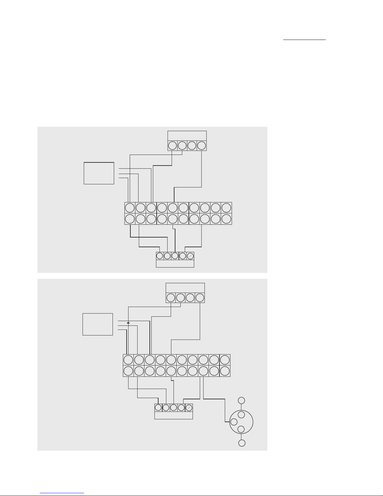
SOLAR HIGH LIMIT CONTROL
These schematic wiring
diagrams depict an IMIT high
limit control stat and the
connections are numbered
accordingly. Where an
alternative is supplied , such as
the solar dierential controller,
connect as per manufacturer’s
instructions.
E C 1 2
HIGH LIMIT CONTROL
Maints supply
double pole
fused spur
230/220 3amp
L
N
E
1 2 3 4 5 6 7 8 9 10
1 2 3 4 5 6 7 8 9 10
B
L
G O
B
R
G
Y
ZONE VALVE
1 2 3 4 5 6 7 8 9 10
1 2 3 4 5 6 7 8 9 10
B
L
G O
B
R
G
Y
ZONE VALVE
L
N
PUMP
E
3
2
E C 1 2
HIGH LIMIT CONTROL
Maints supply
double pole
fused spur
230/220 3amp
L
N
E
E C 1 2
HIGH LIMIT CONTROL
Maints supply
double pole
fused spur
230/220 3amp
L
N
E
1 2 3 4 5 6 7 8 9 10
1 2 3 4 5 6 7 8 9 10
B
L
G O
B
R
G
Y
ZONE VALVE
TYPICAL SCHEMATIC WIRING DIAGRAMS
Page 16
15
EVERFLO STAINLESS UV
UNVENTED HOT WATER CYLINDERS
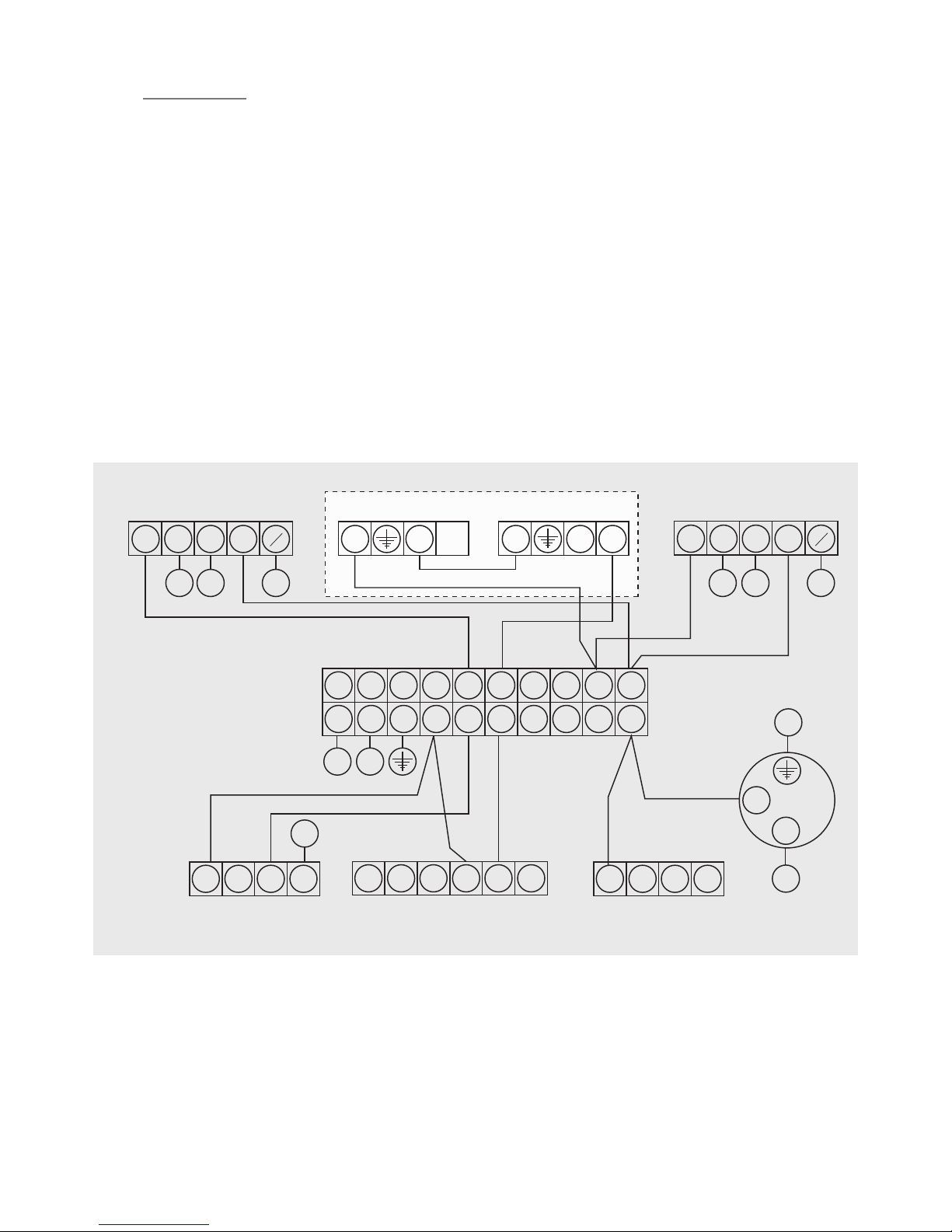
TYPICAL SCHEMATIC WIRING DIAGRAMS
The diagrams shown relate to the components listed. Other
components and other manufacturers’ components may vary in
their wiring requirements, particularly thermostats. Always refer
to manufacturers’ instructions which may override the detail in
order to function correctly.
VARIANT DUAL THERMOSTAT WIRING
WIRING DIAGRAM 2 x T WO PORT ZONE VALVES (S-PLAN)
WIRING DIAGRAM 2 PORT ZONE VALVE (S-PLAN)
VARIANT DUAL THERMOSTAT WIRING
2 PORT (HTG)
Br
G BI O
G
Y
1
2
3 3
2
1
DUAL STAT
2 PORT (DHW)
C
2 C
2
1
Br
G Bl O
G
Y
1 2 3 4 5 6 7 8 9 10
1 2 3 4 5 6 7 8 9 10
WIRING CENTRE
3
L
N
2
L N
1 2 3 4
L N E 4 5 6
1 2 3 4
2
5A SUPPLY
ROOM STAT PROGRAMMER
BOILER
PUMP
Page 17
16
EVERFLO STAINLESS UV
UNVENTED HOT WATER CYLINDERS
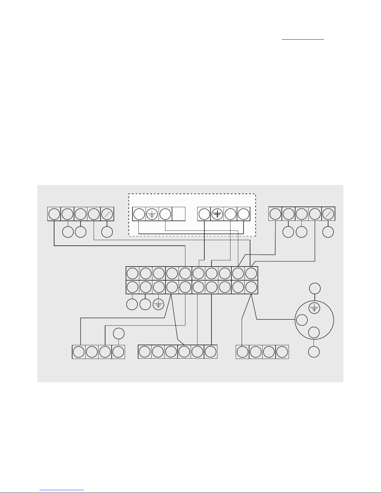
TYPICAL SCHEMATIC WIRING DIAGRAMS
WIRING DIAGRAM THREE PORT MID POSITION VALVE (Y-PLAN) +
TWO PORT VALVE
VARIANT DUAL THERMOSTAT WIRING
WIRING DIAGRAM 3 PORT MID POSITION (Y-PLAN) +2 PORT VALVE
WIRING DIAGRAM 3 PORT MID POSITION (Y-PLAN) + 2 PORT VALVE
VARIANT DUAL THERMOSTAT WIRING
3 PORT (HTG)
W
G BI O
G
Y
7
2
3 3
2
1
DUAL STAT
2 PORT (DHW)
C
2 C
2
1
Br
G Bl O
G
Y
1 2 3 4 5 6 7 8 9 10
1 2 3 4 5 6 7 8 9 10
WIRING CENTRE
3
L
N
2
L N
1 2 3 4
L N E 4 5 6
1 2 3 4
2
5A SUPPLY
ROOM STAT PROGRAMMER
BOILER
PUMP
Page 18
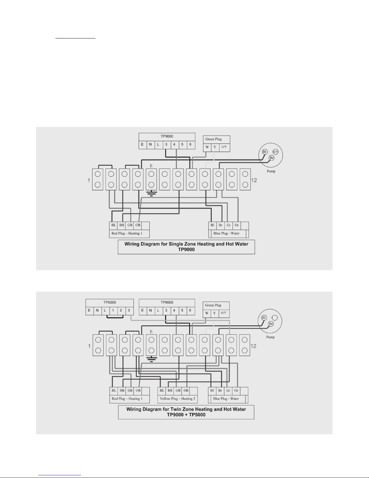
17
EVERFLO STAINLESS UV
UNVENTED HOT WATER CYLINDERS
SINGLE ZONE HEATING
TWIN ZONE HEATING
Connect power supply as per instruction manual. TP9000 terminals 5 & 6 can be used for remote sensor connection.
Connect power supply as per instruction manual. TP9000 terminals 5 & 6 can be used for remote sensor connection.
TYPICAL SCHEMATIC WIRING DIAGRAMS
PLUMBED CYLINDER
Page 19
18
EVERFLO STAINLESS UV
UNVENTED HOT WATER CYLINDERS
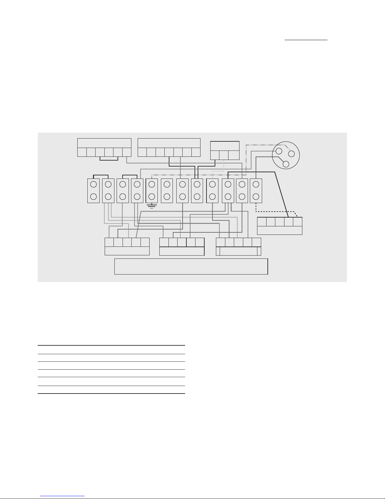
CONNECTED TO BOILER WITH PUMP OVER-RUN FACILITY
E N L 1 2 3
TP5000
E N L 3 4 5
TP9000
0
W Y G/Y
Green Plug
B1
G/Y
Br
L N E SLB LP
Boilder with over run
BL
BR GR OR
Red Plug - Heating 1
BL
BR GR OR
Yellow Plug - Heating 2
B1
Br Gr Or
Blue Plug - Water
Wiring Diagram for Twin Zone Heating and Hot Water
TP9000 + TP5000 to system using boilder to control pump
1 2 3 4 5 6 7 8 9 10 11 12
Pump
INSTRUCTION FOR CONNECTION TO A BOILER WITH PUMP OVER
RUN FACILITY SUCH AS IDEAL LOGIC HEAT
1.Disconnect brown pre-wire pump ex from position 10
2.Reconnect brown pre-wire pump ex to position 12
3.Connect 5 core cable between boiler and wiring control centre
to following positions
WIRING CEN TRE BOILER
TERMINAL 1 PERMANENT LIVE L
TERMINAL 3 PERMANENT NEUTR AL N
TERMINAL 5 PERMANENT EART H E
TERMINAL 10 SWITCH ED LIVE TO BOILER SL B
TERMINAL 12 SWITCH L IVE TO PUMP L P
Page 20

19
EVERFLO STAINLESS UV
UNVENTED HOT WATER CYLINDERS
PRE-PLUMBED
CYLINDER INSTALLATION
COLD MAINS PIPEWORK
Run the cold main through the building to the place where the
EVERFLO STAINLESS UV PRE-PLUMB unit is to be installed. Take
care not to run the cold pipe near hot water or heating pipework
so that the heat pick-up is minimized. Identify the cold water
supply pipe and t an isolating valve (not supplied). A 22mm
BS1010 stopcock can typically be used but a 22mm quarter turn
full bore valve would be better as it does not restrict the ow as
much. Do not use “screwdriver slot” or similar valves. Make the
connection to the inlet control set (Position 2). Ensure that the
arrow points in the direction of the water ow. Select a suitable
position for the expansion vessel. Mount it to the wall using the
bracket provided. Connect the expansion vessel to the cold feed
pipework between the inlet control set and the cold inlet. Ensure
that the top of the vessel is accessible for servicing.
CONNECTING TO THE CYLINDER
All of the pipework connections on the cylinder are 22mm
compression and supplied complete with gland nuts and olives, in
the Accessory Kit box. Only connect 22mm Table X copper tube to
these connections. Cut the tube with a pipe cutter and ensure no
sharp edges or burrs protrude. Slide both gland nut and olive onto
the tube and push tube fully home into the connection, ensuring
the tube end fully bottoms on the connection recess. Smear the
outer wall of the olive with plumbing paste and tighten gland nut
in the prescribed manner. Upon lling/commissioning, ensure all
connections are completely watertight.
BALANCED COLD CONNECTION
If there are to be showers, bidets or monobloc taps in the
installation then a balanced cold supply is necessary. There is a
22mm balanced connection on the inlet set.
HOT WATER PIPEWORK
Connect to HWDO (Position 1 on diagram). Run the rst part of the
hot water distribution pipework in 22mm. This can be reduced to
15mm and 10mm as appropriate for the type of tap etc. Your aim
should be to reduce the volume of the hot draw-o pipework to
a practical minimum so that the time taken for the hot water is as
quick as possible. Where monobloc mixing taps and showers are
used, these should be installed to comply with the Water Supply
(Water Fittings) Regulations 1999. If these devices are supplied
with un-balanced supplies there should be single check valves
installed at both inlets, to stop over pressurising of either supply.
CONNECTIONS FOR INDIRECT UNITS
Connect to the boiler ow and return (Positions 19 & 14) lines.
An additional expansion vessel and safety valve is supplied. The
boiler may be Gas, Electric or Oil but must be under eective
thermostatic control. Uncontrolled heat sources such as some
AGA’s, back boilers, solid fuel stoves, etc. are NOT SUITABLE.
Please contact our Technical department for guidance. Connect
to (Position 9 & 13) for the radiator circuits. Twin zone heating unit
are supplied with 2 port zone valves in positions 9a and 9b.
CONNECTIONS FOR SOLAR COILS
Connect to the solar coil as detailed on page 13 ensure the solar
pump is connected via the over temperature cut out as described
on page 13.
SECONDARY CIRCULATION
EVERFLO cylinder can be used with secondary circulation. An
appropriate WRAS approved bronze circulator should be used in
conjunction with a non-return valve to prevent backow. On large
secondary circulation systems it may be necessary to incorporate
an extra expansion vessel into the circuit to accommodate the
increased system water volume. A secondary return boss is tted
as standard on 210, 250 & 300 ltr units (Position 17). On smaller
sizes, tee into the cold feed pipe above the drain.
IMMERSION HEATERS
Only immersion heaters with a thermal cutout may be used. To
help ensure this, the immersion heaters have a special 1¾” thread.
They are rated at 3 kW at 240 V and are of a low noise Incoloy
construction. They have both a thermostat and a high limit cutout.
Please order the correct replacement via ourselves; tting nonapproved immersions may aect your guarantee. When tting,
ensure the ‘O’ ring is positioned correctly on the head of the
immersion heater and lubricate before tting. Fit it by hand until
almost home then tighten gently as the ‘O’ rings will seal easily.
The electrical supply to each immersion heater must be fused at
13A via a double pole isolating switch to BS 3456. The cable must
be 2.5mm2 heat resistant (85°C HOFR) sheathed ex complying
to BS 6141:1981 Table 8. Do not operate the immersion heater/s
until the unit is full of water. Do not operate the immersion
heater/s if any sterilisation liquid is in the cylinder as this will cause
premature failure.
ELECTRICAL CONNECTIONS
Complete the wiring – use the appropriate wiring diagrams on
pages 17 & 18.
COMMISSIONING
Carry out commissioning as per instructions on page 21 and in line
with boiler manufacturer’s instructions for the heating and the
primary circuit. Primary pipework must be lled, bled and tested
in accordance with the boiler manufacturer’s instructions, to avoid
damage to the circulation pump.
Page 21
20
EVERFLO STAINLESS UV
UNVENTED HOT WATER CYLINDERS
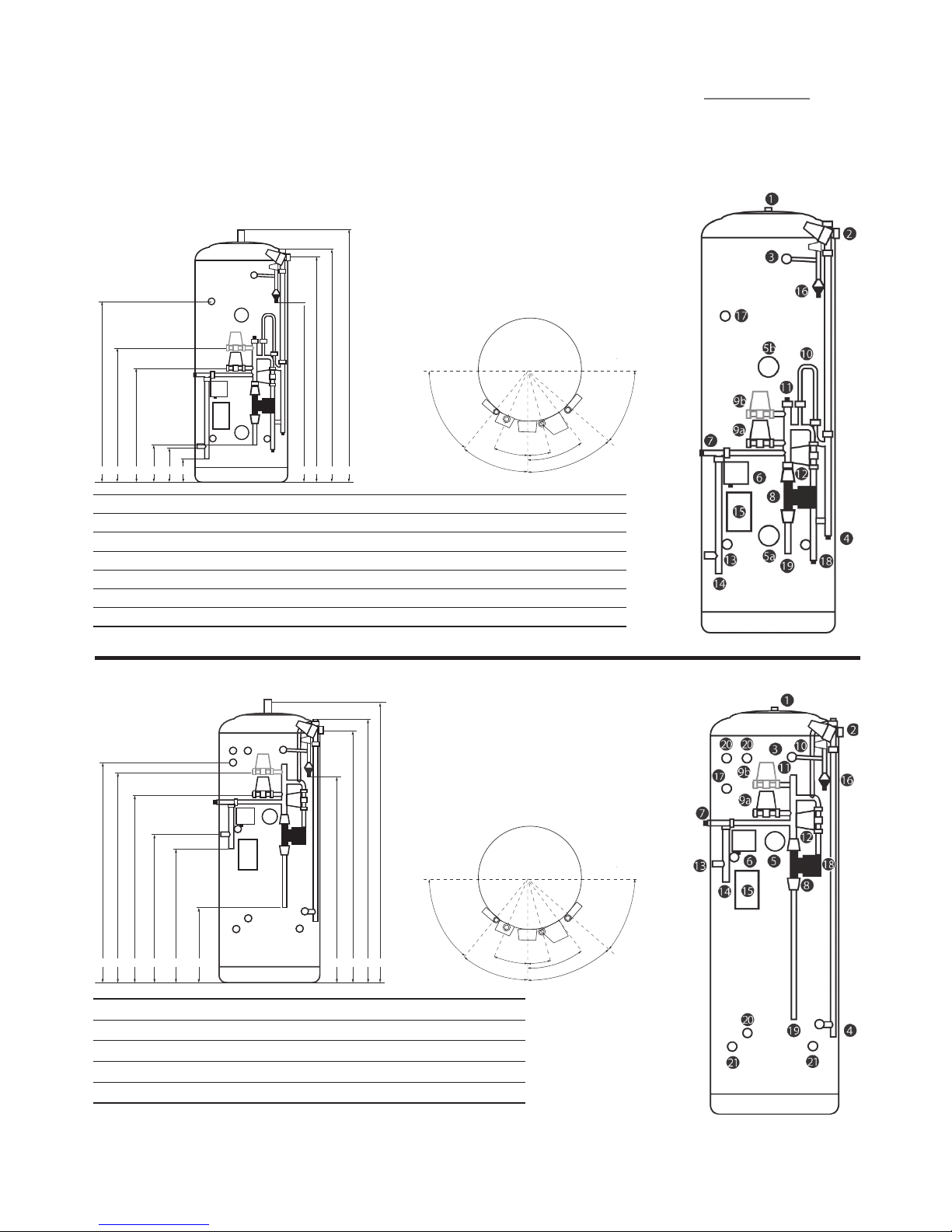
EVERFLO STAINLESS UV SOLAR INDIRECT PREPLUMBED
IEVERFLO STAINLESS UV NDIRECT PREPLUMBED
All Dimensions are in mm and are of the cased unit.
N/F = not tted.
18
J I H F E G D C B A
40.0˚
45.0˚
15.0˚
25.0˚
35.0˚
50.0˚
45.0˚
CODE A B C D E F G H I J
ET180P4 1297 1258 1211 94 8 560 635 48 0 850 970 N /F
ET210P4 1485 1446 1399 1136 6 65 740 585 955 1075 1150
ET25 0P4 1735 1696 1649 1386 8 30 90 5 770 1130 1250 1400
ET30 0P4 204 8 2 009 1962 1699 859 93 4 799 1159 1279 160 0
G
J I H G F E D C B A
CODE A B C D E F G H I J
EN120P4 92 2 883 836 573 171 246 102 470 59 0 N/F
EN150P4 1109 1070 1023 760 211 286 140 508 628 N/ F
EN180P4 1297 1258 1211 948 211 286 320 690 810 N/ F
EN210P4 1485 144 6 1399 1136 246 321 320 690 810 1150
EN250P4 1735 1696 1649 1386 246 321 320 690 810 1400
EN300 P4 2048 20 09 1962 1699 246 321 418 784 904 1600
40.0˚
45.0˚
15.0˚
25.0˚
35.0˚
50.0˚
45.0˚
For Twin Zone codes please replace P4 with PT4
For Twin Zone codes please replace P4 with PT4
Page 22

COLD MAINS PIPEWORK
Run the cold main through the building to the place where
the EVERFLO STAINLESS UV SYSTEM FIT PRE-PLUMB unit is to
be installed. Take care not to run the cold pipe near hot water
or heating pipework so that the heat pick-up is minimized.
Identify the cold water supply pipe and t an isolating valve (not
supplied). A 22mm BS1010 stopcock can typically be used but a
22mm quarter turn full bore valve would be better as it does not
restrict the ow as much. Do not use “screwdriver slot” or similar
valves. Make the connection to the inlet control set (Position 2).
Ensure that the arrow points in the direction of the water ow.
Select a suitable position for the expansion vessel. Mount it to
the wall using the bracket provided. Ensure the charge in the
vessel is 3 Bar. Connect the expansion vessel to the Tee in the
cold feed pipework between the inlet control set and the cold
inlet. On large secondary circulation systems it may be necessary
to incorporate an extra expansion vessel into the circuit to
accommodate the increased system water volume. Ensure that the
top of the vessel is accessible for servicing.
CONNECTING TO THE CYLINDER
All of the pipework connections on the cylinder are 22mm
compression and supplied complete with gland nuts and olives, in
the Accessory Kit box. Only connect 22mm Table X copper tube to
these connections. Cut the tube with a pipe cutter and ensure no
sharp edges or burrs protrude. Slide both gland nut and olive onto
the tube and push tube fully home into the connection, ensuring
the tube end fully bottoms on the connection recess. Smear the
outer wall of the olive with plumbing paste and tighten gland nut
in the prescribed manner. Upon lling/commissioning, ensure all
connections are completely watertight.
BALANCED COLD CONNECTION
If there are to be showers, bidets or monobloc taps in the
installation then a balanced cold supply is necessary. There is a
22mm balanced connection on the inlet set.
HOT WATER PIPEWORK
Connect to HWDO (Position 1 on diagram). Run the rst part of the
hot water distribution pipework in 22mm. This can be reduced to
15mm and 10mm as appropriate for the type of tap etc. Your aim
should be to reduce the volume of the hot draw-o pipework to
a practical minimum so that the time taken for the hot water is as
quick as possible. Where monobloc mixing taps and showers are
used, these should be installed to comply with the Water Supply
(Water Fittings) Regulations 1999. If these devices are supplied
with un-balanced supplies there should be single check valves
installed at both inlets, to stop over pressurising of either supply.
CONNECTIONS FOR INDIRECT UNITS
Connect to the boiler ow and return (Positions 12 & 14) lines.
An additional expansion vessel and safety valve is supplied.
Uncontrolled heat sources such as some AGA’s, back boilers, solid
fuel stoves, etc. are NOT SUITABLE. Please contact our Technical
department for guidance. Connect to (Position 9 & 14) for the
radiator circuits. Twin zone heating unit are supplied with 2 port
zone valves in positions 9a and 9b.
CONNECTIONS FOR SOLAR COILS
Connect to the solar coil as detailed on page 13 ensure the solar
pump is connected via the over temperature cut out as described
on page 13.
SECONDARY CIRCULATION
EVERFLO cylinder can be used with secondary circulation. An
appropriate WRAS approved bronze circulator should be used in
conjunction with a non-return valve to prevent backow. On large
secondary circulation systems it may be necessary to incorporate
an extra expansion vessel into the circuit to accommodate the
increased system water volume. A secondary return boss is tted
as standard on 210, 250 & 300 ltr units (Position 17). On smaller
sizes, tee into the cold feed pipe above the drain.
IMMERSION HEATERS
Only immersion heaters with a thermal cutout may be used. To
help ensure this, the immersion heaters have a special 1¾” thread.
They are rated at 3 kW at 240 V and are of a low noise Incoloy
construction. They have both a thermostat and a high limit cutout.
Please order the correct replacement via ourselves; tting nonapproved immersions may aect your guarantee. When tting,
ensure the ‘O’ ring is positioned correctly on the head of the
immersion heater and lubricate before tting. Fit it by hand until
almost home then tighten gently as the ‘O’ rings will seal easily.
The electrical supply to each immersion heater must be fused at
13A via a double pole isolating switch to BS 3456. The cable must
be 2.5mm2 heat resistant (85°C HOFR) sheathed ex complying
to BS 6141:1981 Table 8. Do not operate the immersion heater/s
until the unit is full of water. Do not operate the immersion
heater/s if any sterilisation liquid is in the cylinder as this will cause
premature failure.
ELECTRICAL CONNECTIONS
Complete the wiring – use the appropriate wiring diagrams on
pages 17 & 18. as reference. Connections required listed below.
1 Permanent live
3 Neutral
5 Earth
7 Heating Zone 1 ON from controls
8 Hot Water ON from controls
9 Heating Zone 2 ON from controls (2 zone only)
10 Boiler and pump run
COMMISSIONING
Carry out commissioning as per instructions on page 23 and in
line with boiler manufacturer’s instructions for the heating and
the primary circuit. Primary pipework must be lled, bled and
tested in accordance with the boiler manufacturer’s instructions,
to avoid damage to the circulation pump.
INSTALLATION
SYSTEM FIT
21
EVERFLO STAINLESS UV
UNVENTED HOT WATER CYLINDERS
Page 23
22
EVERFLO STAINLESS UV
UNVENTED HOT WATER CYLINDERS
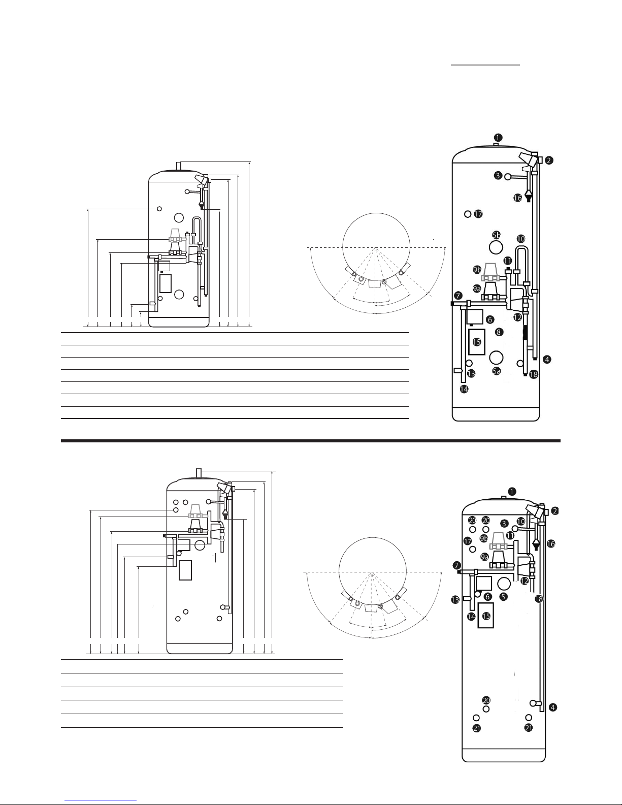
All Dimensions are in mm and are of the cased unit.
N/F = not tted.
CODE A B C D E F G H I J
ET180P5 1297 1258 1211 94 8 560 635 780 850 970 N/ F
ET210P5 1485 1446 1399 1136 6 65 740 885 955 1075 1150
ET25 0P5 1735 1696 1649 1386 8 30 90 5 1070 1130 1250 1400
ET30 0P5 204 8 2 009 1962 1699 859 93 4 1100 1159 1279 1600
For Twin Zone codes please replace P5 with PT5
40.0˚
45.0˚
15.0˚
25.0˚
35.0˚
50.0˚
45.0˚
18
J I H F EG D C B A
EVERFLO STAINLESS UV SOLAR INDIRECT SYSTEM FIT PREPLUMBED
For Twin Zone codes please replace P5 with PT5
CODE A B C D E F G H I J
EN120P5 92 2 883 836 573 171 246 40 0 470 59 0 N/F
EN150P5 1109 1070 1023 760 211 286 44 0 50 8 628 N/F
EN180P5 1297 1258 1211 948 211 286 620 69 0 810 N/F
EN210P5 1485 144 6 1399 1136 246 321 620 690 810 1150
EN250P5 1735 1696 164 9 1386 246 321 620 69 0 810 1400
EN300 P5 2048 20 09 1962 1699 246 321 670 784 904 1600
40.0˚
45.0˚
15.0˚
25.0˚
35.0˚
50.0˚
45.0˚
IEVERFLO STAINLESS UV NDIRECT SYSTEM FIT PREPLUMBED
J I H G F E D C B A
Page 24

23
EVERFLO STAINLESS UV
UNVENTED HOT WATER CYLINDERS
COMMISSIONING
SERVICING
FLUSHING & FILLING
Check that the pressure in the expansion vessel is 3 bar (45PSI),
i.e. the same as the setting of the pressure reducing valve. The
valve is of the car tyre (Schrader) type. Check all the connections
for tightness including any factory made connections such as the
immersion heater and the temperature and pressure relief valve.
Before lling, open the hot tap furthest away from the EVERFLO
STAINLESS UV to let air out. Open the cold main isolation valve
and allow the unit to ll. When water ows from the tap allow
it to run for a short while to ush through any dirt, swarf or ux
residue. Close the tap and open every other hot tap in turn to
purge all remaining air.
DIRECT UNITS
After lling with water and after sterilisation liquid has been
purged, switch on the power to the immersion heaters and allow
the unit to start to heat. The immersion heater is supplied preset
at 55°C. Turning fully to + sets to approx 65°C. Allow unit to heat
up, adjust the thermostat so that the heater switches o at 60°C.
Record information on commissioning check list (Page 32).
INDIRECT UNITS
Consult the boiler manufacturer’s commissioning instructions and
ll the primary circuit. Ensure the lever on the two port valve is
set to the lling position. When full, move the lever back. Switch
the programmer to Domestic Hot Water (DHW) and allow the
unit to start to heat. Adjust the dial of the dual thermostat to
between 55°C and 65°C as required. Allow unit to heat up, adjust
the thermostat so that the heater switches o at 60°C. Record
information on commissioning check list (Page 32).
STORAGE TEMPERATURE
The recommended storage temperature for both direct and
indirect cylinders is 60-65°C. In hard water areas consideration
should be given to reducing this to 50-55°C. In many healthcare
applications the guidance on Legionella control and safe water
delivery temperatures will require storing the water at 60-65°C,
distributing at 50- 55°C and using thermostatic mixing valves to
control the nal temperature. For details consult the NHS Estates
Guidance on safe hot water temperatures.
SAFETY VALVE CHECKS
During heat-up there should have been no sign of water coming
from either the expansion relief valve or the temperature/pressure
relief valve. Now hold both of these safety valves fully open, in
turn, allowing as much water as possible to ow through the
tundish. Check that your discharge pipework is free from debris
and is carrying the water away to waste eciently. Release the
valves and check that they reseat properly. On Completion of
commissioning, ll in the Benchmark check list and leave with the
house owner.
BENCHMARK SCHEME
The installer must follow the Benchmark code of practice for
the Benchmark certication to be valid. The benchmark code of
practice can be found on the internet using the following internet
site www.centralheating.co.uk and follow links.
GENERAL
Servicing should only be carried out by competent installers and
any spare parts used must be ocial parts available from the
EVERFLO helpdesk. NEVER bypass any safety devices or operate the
unit without them being fully operational.
DRAINING
Isolate from the electrical supply to prevent the immersion heaters
burning out. Turn o the boiler. Isolate the unit from the cold mains.
Attach a hose to the draining tap ensuring that it reaches to a level
below the unit (this will ensure an ecient syphon is set up and the
maximum amount of water is drained from the unit). First open the
hot tap closest to the unit and then open the draining tap.
WARNING: WATER DRAINED OFF MAY BE VERY HOT!
IMPORTANT: After draining the cylinder do not close the hot tap
until the cylinder has fully cooled, failure to follow this instruction
may result in damage to the cylinder and will invalidate the
guarantee.
ANNUAL MAINTENANCE
EVERFLO requires an annual service in order to ensure safe working
and optimum performance. It is essential that the following checks
are performed by a competent installer
on an annual basis. Commonly this is done at the same time as the
annual boiler service.
1) Twist the cap of the expansion relief valve on the inlet control
set and allow water to ow for 5 seconds. Release and make sure it
resets correctly. Repeat with the pressure / temperature relief valve.
In both cases check that the discharge pipework is carrying the
water away adequately. If not, check for blockages etc. and clear.
WARNING: THE WATER DISCHARGED MAY BE VERY HOT!
2) Check that any immersion heaters tted are working correctly
and that they are controlling the water at a temperature between
55°C and 65°C.
3) Check the pressure in the expansion vessel is charged to 3 bar.
Turn o the water supply to the unit and open a hot tap rst. The air
valve on expansion vessel is a Schrader (car tyre ) type. Air or CO2
may be used to charge the expansion vessel.
4) Unscrew the head on the inlet control set and clean the mesh
lter within.
5) The Benchmark Log Book supplied with this unit should be
updated at each service. (Page 33)
YOUR GUARANTEE MAY BE VOID WITHOUT PROOF OF ANNUAL
SERVICING.
Page 25

24
EVERFLO STAINLESS UV
UNVENTED HOT WATER CYLINDERS
FAULT FINDING
SPARE PARTS
A full range of spare parts is available from EVERFLO Cylinders. Tel:
0330 999 0035 see page 2 for part numbers.
USER INSTRUCTIONS
Your stainless system is automatic in normal use and requires only
annual servicing. You should employ a competent installer to
perform the annual servicing. Normally this is timed to coincide
with the annual boiler service.
IF WATER IS FLOWING FROM THE SAFETY VALVES THROUGH THE
TUNDISH THIS INDICATES A FAULT CONDITION AND ACTION IS
NEEDED.
If this water is hot, turn the boiler and / or the immersion heater
o. Do not turn o the water until the discharge runs cool. The
discharge may also stop.
CALL OUT A COMPETENT PLUMBER TO SERVICE THE UNIT.
Tell them you have a fault on an unvented cylinder. We stock all
the spare parts they may need (see page 2).
DRAINING
IMPORTANT: After draining the cylinder do not close the hot tap
until the cylinder has fully cooled, failure to follow this instruction
may result in damage to the cylinder and will invalidate the
guarantee.
The installer must follow the Benchmark code of practice for the
Benchmark certication to be valid. Please see page 28 for further
details.
FAULT POSSIBLE CAUSE SOLUTION
Water escapi ng from the case Compressi on tting on hot - draw o n ot sealing Check /remake joint with seal ing paste
Cold water at H ot taps Di rect - immersion h eater not switched on o r cutout has trigger ed Check / reset
Indirec t - boiler not worki ng Check boi ler - consult boiler man ufacturers' ins tructions
Indirec t - motorised valve fa ult Check plum bing / wiring to motori sed valve
Indirec t - cutout in dual stat has o perated Reset and i nvestigate cause
Water dischar ges from expansio n relief
valve
If continua l - pressure reducing va lve ( part of inlet cont rol set) may
not be ope rating correctly
Check outl et pressure from inl et control set is 3 bar.
If continua l - expansion relief v alve seat may be damage d Remove car tridge - check sea t and renew if necessar y
If intermi ttent - expansion ve ssel charge may have redu ced / bladder
perishe d
Check pres sure in expansion vess el. Recharge to 3 bar if n ecessary. If
bladder p erished replace ves sel.
Unit it bein g back pressurised With cyl inder cold check pre ssure in cylinder. If th is is the same as
the incomin g mains pressure then yo u are getting back feed. Install a
balanced co ld supply (see page 6)
Water dischar ges from temperatu re &.
pressure re lief valve
Unit has overh eated - thermal contro ls have failed "Switch o p ower to boiler and imme rsion heaters.
Leave water sup ply on. Wait until disch arge stops.
Isolate wate r supply and replace i f faulty"
Milky / cl oudy water Oxygenated w ater Water from any pr essurised system w ill release oxyge n bubbles when
owing. T he bubbles will set tle out.
No hot water ow Cold main o Check and op en stopcock
Strainer bl ocked in pressure re ducing valve Isolate water sup ply and clean
Inlet contr ol set may be tted in correctly Check and re t as required
Noise duri ng hot water draw-o
-typi cally worse in the mor ning.
Loose airi ng cupboard pipew ork Install extr a clips
Hot or warm w ater from cold tap If tap ru ns cold after a minute or s o the pipe is picking u p heat from
heating pi pework.
Insulate / re -route
Page 26

25
EVERFLO STAINLESS UV
UNVENTED HOT WATER CYLINDERS
GUARANTEE TERMS AND CONDITIONS
This guarantee applies only to the product & parts supplied by the
cylinder manufacturer and its associated brands (hereafter the
term ‘product’ refers to Evero Stainless UV).
The manufacturer guarantees to the homeowner that for a period
of 2 years from the date of commissioning or legal completion if
new build, that the products and associated components installed
will - Conform to manufacturers specication; and be free from
defects in materials and workmanship, subject to the conditions
set out below.
Please note: this guarantee excludes all pipework and connections
and excludes any ancillary equipment as may be connected to the
product. (Example: descaling equipment, water softeners)
The guarantee is extended to a total of 25 years for the stainless
steel inner vessel in domestic properties.
This guarantee means that the manufacturer will take
responsibility for the cost of guarantee repair of a product by a
Service Engineer approved by the Evero services team, so that
the product shall conform to the manufacturers specication.
The manufacturer reserves the right, at it’s discretion to replace a
product or major component where it considers it to be beyond
economical repair.
In the event of a breakdown during the guarantee period please
call our Customer Service Department on:
0330 999 0035 - UK
Guarantee repair is free of charge to you for any parts and labour,
providing all the guarantee conditions have been met.
GUARANTEE TERMS & CONDITIONS
Please read the following conditions before registering your
product and before seeking any guarantee service support
IMPORTANT: The Manufacturer guarantee is subject to the home
owner registering with the Evero Customer Service Department
within 30 days of commissioning / occupation if new build to
conrm:
• Product Make / Model
• Details installation (can be found in Benchmark Log Book left by
installer)
Please complete the registration card provided and return to:
Customer Service Department, Evero Cylinders, Tadman Street,
Wakeeld, WF1 5QU, UK
or register the product on-line at
www.everocylinders.co.uk
If you do not register the Product then the manufacturers
Guarantee is limited to twelve months from the date of
commissioning.
The product must be maintained by a competent person* within
12 months after commissioning, and thereafter at 12 monthly
intervals. The manufacturer reserves the right to seek evidence of
this maintenance to our reasonable satisfaction before approving
any guarantee servicing / repairs. This may include evidence of
completed BenchmarkTM log book and service agreement /
invoice.
Annual Services are available from the Customer Service/
Technical Support team.
*A competent person is a business that has been adjudged by
an accredited body** to be suciently competent to self-certify
that its work complies with Document (G) Part 3 of the Building
Regulations of England and Wales
*May Include SEI registered installers and/or FAS trained plumbers
who have completed the renewables technology module
** An example of which is BPEC
Any exchanged component will become the legal property of the
manufacturer.
This guarantee is valid provided that:
• The product has been installed by a competent installer and as
per the instructions contained in the installation manual and all
relevant Codes of Practice and Regulations in force at the time of
installation.
• Any disinfection has been carried out in accordance with BS
6700.
• The product has not been modied in any way.
• The system is fed from domestic mains water supply complience
with water regulations 2000
• The product has only been used for the storage of wholesome
water (max. 250mg/l chloride – for hard water areas, the
manufacturer recommend the use of an electrolytic scale reducer)
• Any 3rd party labour charges associated with replacing the unit
or any of its components have been authorised in advance by the
Customer Service/ Technical Support team.
• It has only been used for the storage of potable water.
• The product has not been subjected to frost, nor has it been
tampered with or been subjected to misuse or neglect.
• No factory tted parts have been removed for unauthorised
repair or replacement.
• The BenchmarkTM Commissioning Checklist and Service
Record included with this product Installation Manual have been
completed.
• Regular maintenance has been carried out by a competent
person in accordance with the requirements set out in the
maintenance section of the installation manual.
• The owner or installer has registered the product on-line at
www.everocylinders.co.uk within 30 days of purchase. Failure to
do so may result in a reduced warranty period.
• Evidence of purchase and date of supply must be submitted
upon making a claim.
• Any replacement parts used should be authorised Evero
Cylinders spare parts.
Page 27

26
EVERFLO STAINLESS UV
UNVENTED HOT WATER CYLINDERS
GUARANTEE TERMS AND CONDITIONS
•If a defect arises and a valid claim is received within the Warranty
Period, at its option and to the extent permitted by law Evero
Cylinders shall either
(1) Repair the defect at no charge, using new or refurbished
replacement parts or
(2) Exchange the product with a product that is new or which has
been manufactured using new or serviceable used parts or
(3) Refund the purchase price or a reasonable proportion of the
purchase price.
The manufacturer reserves the right to inspect the product at
your home before proceeding with any guarantee repair or
replacement.
Any valid guarantee claim or guarantee service does not extend
the original guarantee period. Information on extend warranties is
available upon request.
The guarantee only applies to the property at which the product
was originally installed and applied only to properties in the
United Kingdom & Ireland. The guarantee is fully transferable from
a change of legal ownership of the property.
EXCLUSIONS – The guarantee does not cover:
The manufacturer will not be liable for any fault or costs arising
from incorrect installation, incorrect application, lack of regular
maintenance or neglect, accidental damage, malicious damage,
misuse, any alteration, tampering or repair carried by a non
competent person.
• The product if the factory tted temperature and pressure relief
valve has been tampered with or removed.
• Neither the Distributor nor Manufacturer shall be responsible for
any consequential damage howsoever caused.
• The eects of scale build up or the eects of corrosion.
• Any consequential losses caused by the
failure or malfunction of the product.
• Faults and any associated costs arising from lack of power or
water.
• Failure incurred by water contamination, air pollution and natural
disasters.
• This guarantee is not valid for installations outside the United
Kingdom.
• Any consequential loss, loss of prots, revenues or receipts
howsoever arising from any non-conformity or defect aecting
the product or from any delay in repair or replacement of the
product.
• Any loss or damage caused by delay in conduct of services or
supply of parts required to rectif y the non-conformity or defect.
(provided the manufacturer will use all reasonable eorts to
ensure services are performed on a timely basis).
• For repair or replacement of any Product consumables or
decorative nishes, such as lters and casings.
This guarantee does not aect any legal rights you may have as
a consumer under applicable national legislation governing your
purchase of this product
The manufacturer shall make nal determination as to the validity
of any guarantee claim, and shall be entitled to charge you all
reasonable costs incurred in investigating the claim where there
is no fault found, or the guarantee claim is rejected in accordance
with these conditions.
Customer Service Department
Evero Cylinders
Tadman Street
WAKEFIELD
WF1 5QU
U.K
Page 28

27
EVERFLO STAINLESS UV
UNVENTED HOT WATER CYLINDERS
Home Owner Name
Home Address
Post code
Make of product Model/size
Serial Number
Installers Contact details
(can be found in benchmark log book)
Date of installation
can be found in benchmark log book)
Signature of homeowner
Date
Or Signature of developer
(If new build)
Date
To be completed by the home owner. Please use this card to
register within 30 days of commissioning / occupation if new build
to benet from the manufacturer 2 year guarantee.
By completing this form, you consent to Evero Cylinders and their
agents holding and using those details for all purposes directly
related to the administration and conduct of guarantee services.
Apart from the necessary usage, your personal data will not be
disclosed to third parties.
GUARANTEE REGISTRATION CARD
Page 29

28
EVERFLO STAINLESS UV
UNVENTED HOT WATER CYLINDERS
TECHNICAL SPECIFICATIONS
Element Ra ting 3kW 240 V
Thread Type 1 3/4” BSP
Fuse Requir ement 13A via Double Pole Sw itch
Control Th ermostat for Elem ent - Temperat ure Range 45
o
C - 65oC
High Limit T hermostat for Ele ment - Temperature Set Poi nt 85
o
C
Maximum I nlet Water Pressure 12 Bar
Operati ng Pressure 3.0 Bar
Expansi on Valve Opening Pressu re 6.0 Bar
Expansi on Vessel Charge Pressure 3.0 Bar
Maximum O perating Pressure 7.0 Bar
Opening P ressure of T & P Valve 7.0 Bar
Opening Temp erature of T & P Valve 90
o
C
Maximum Pr essure on Primary Ci rcuit (Indirect & So lar Coil) 3.5 Bar
Element Ra ting 3kW 240 V
Thread Type 1 3/4” BSP
Fuse Requir ement 13A via Double Pole Sw itch
Control Th ermostat for Elem ent - Temperat ure Range 45
o
C - 65oC
High Limit T hermostat for Ele ment - Temperature Set Poi nt 75
o
C
PRESSURE SPECIFICATIONS
DIRECT IMMERSION ELEMENT SPECIFICATIONS
INDIRECT IMMERSION ELEMENT SPECIFICATIONS
Page 30

29
EVERFLO STAINLESS UV
UNVENTED HOT WATER CYLINDERS
SPECIFICATION
CYLINDER DETAILS & PERFORMANCE
PRODUC T CODE
WEIGHT EM PTY
WEIGHT FUL L
CAPACITY
Designated Solar Volume
Fossil Fuel Volume
HEAT-UP TIME
70% RE-HE AT T IME
INDIREC T COIL
SURFACE AREA
INDIREC T COIL
CAPACITY
INDIREC T
COIL kW RATING
SOLAR COIL
SURFACE AREA
SOLAR COIL
CAPACITY
Heat Loss (kW/24H r)
EVERFLO DIR ECT SLIMLINE
EDS60 20 80 60 - - 55m - N/A N/A N/A N/A N/A 0.99
EDS90 29 120 90 - - 80 m - N/A N/A N/A N /A N/A 1.05
EDS120 38 160 120 - - 105m - N/A N/A N/A N/A N/A 1.12
EDS150 46 200 150 - - 125m - N/A N/A N/A N/A N/A 1.29
EDS180 54 235 180 - - 140m - N/A N/A N/A N/A N/A 1.37
EDS210 60 270 210 - - 160m - N/A N/A N/A N/A N/A 1.64
EVERFLO IND IRECT SLIMLINE
ENS60 26 90 60 - 10m 45s 8m 02s 0.67 3.69 17.2 N/A N/A 0.99
ENS90 36 130 90 - 17m 22s 15m 12 s 0.67 3.69 16.1 N/A N /A 1.05
ENS120 44 165 120 - 25m 01s 16m 25s 0.67 3.69 19.0 N/A N/A 1.12
ENS150 52 205 150 - 26m 24s 19m 37s 0.77 4 .26 19.5 N/A N/A 1.29
ENS180 6 0 240 180 - 32m 14s 23m 05s 0.77 4. 26 20. 4 N/A N/A 1.37
ENS210 68 280 210 - 36m 36s 27m 40s 0.77 4.26 23.4 N/A N/A 1.64
EVERFLO DIR ECT
ED90 25 115 90 - - 85m - N/A N /A N/A N/A N/A 0.99
ED120 30 150 120 - - 110m - N/A N/A N/A N /A N/A 1.13
ED150 35 185 150 - - 135m - N/A N/A N/A N /A N/A 1.30
ED180 40 220 180 - - 160m - N/A N/A N /A N/A N/A 1.40
ED210 45 255 210 - - 185m - N/A N/A N/A N /A N/A 1.68
ED250 50 300 250 - - 225m - N/A N /A N/A N/A N/A 1.95
ED300 55 355 300 - - 270m - N /A N/A N/A N/A N/A 2.20
EVERFLO IND IRECT
EN90 30 120 90 - 20m 25s 14m 18s 0.67 3 .69 15.78 N/A N/A 0.99
EN120 35 155 120 - 23m 47s 18m 00s 0.67 3.69 18.35 N/A N /A 1.13
EN150 40 190 150 - 29m 36s 20m 35s 0.77 4.26 19.07 N/A N /A 1.30
EN180 45 225 180 - 31m 58s 22m 47s 0.77 4.26 20.28 N/A N/A 1.40
ENI210 50 260 210 - 33m 05s 26m 16s 0.86 4.83 23.08 N/A N/A 1.68
EN250 55 305 250 - 41m 18s 28m 20s 0.86 4 .83 24.40 N/A N/A 1.95
EN300 60 360 300 - 46 m 01s 32m 52s 0.86 4.83 24.87 N/A N/A 2.20
Page 31

30
EVERFLO STAINLESS UV
UNVENTED HOT WATER CYLINDERS
PRODUC T CODE
WEIGHT EM PTY
WEIGHT FUL L
CAPACITY
Designated Solar Volume
Fossil Fuel Volume
HEAT-UP TIME
70% RE-HE AT T IME
INDIREC T COIL
SURFACE AREA
INDIREC T COIL
CAPACITY
INDIREC T
COIL kW RATING
SOLAR COIL
SURFACE AREA
SOLAR COIL
CAPACITY
Heat Loss (kW/24H r)
EVERFLO SOL AR DIRECT
ESD150 40 190 150 - 31m 05s 2 2m 16 s N /A N/A N/A 0.67 3.69 1.30
ESD180 45 225 180 - 33m 30s 23 m 34s N/A N/A N/A 0.67 3 .69 1.40
ESD210 50 260 210
- 33m 05s 26 m 33s N/A N/A N/A 0 .86 4.83 1.68
ESD250 55 3 05 250 - 41m 18s 28m 20s N/A N/A N/A 0 .86 4.83 1.95
ESD300 60 360 30 0 - 46m 01s 32m 52s N/A N /A N/A 0.8 6 4.83 2.20
EVERFLO SOL AR INDIRECT
ET150 45 200 150 22m 50s 11m 44s 0.67 3. 69 17.2 0.67 3.69 1.30
ET180 50 2 35 180
25m 15s 17m 02s 0 .67 3.69 20.2 0.67 3 .69 1.40
ET210 55 270 210
28m 31s 15m 50s 0.77 4.26 23.4 0. 86 4.83 1.68
ET250 60 315 25 0
31m 42s 22m 42s 0.77 4.26 28 .3 0.86 4.83 1.95
ET300 65 370 30 0 36m 04s 21m 30s 0.86 4 .83 29.2 0.86 4.83 2 .20
EVERFLO IND IRECT PRE-PLUMB ED
EN120P4 45 165 120 - 23m 47s 18m 00s 0.67 3.69 18.35 N/A N/A 1.13
EN150P4 50 20 0 150 - 31m 05s 22m 16s 0.77 4.26 19.07 N/A N /A 1.30
EN180P4 55 2 35 180
- 31m 58s 22m 47s 0.7 7 4.26 20.28 N/A N/A 1.40
EN210P4 60 270 210 - 35m 30s 26m 16s 0. 86 4.83 23.08 N/A N/A 1.68
EN250P4 65 315 2 50 - 41m 0 8s 30m 06s 0.86 4 .83 24.40 N/A N/A 1.95
EN300P4 70 320 3 00 - 49m 40s 36m 12s 0 .86 4.83 24.87 N/A N/A 2.20
EVERFLO SOL AR INDIRECT PRE -PLUMBED
ET180P4 6 0 240 180 25m 15s 17m 02s 0.67 3.69 20 .2 0.67 3.69 1.40
ET210P4 65 275 210 28m 31s 15m 50s 0.77 4.26 23.4 0. 86 4.83 1.68
ET250P4 70 320 250 31m 42s 22m 42s 0.77 4.26 28.3 0 .86 4.83 1.95
ET300 P4 75 375 300 36m 04s 21m 30s 0. 86 4.83 29.2 0.86 4 .83 2.20
EVERFLO IND IRECT SYSTEM FIT PR E-PLUMBED
EN120P5 43 163 120 - 23m 47s 18m 00s 0.67 3. 69 18.35 N/A N /A 1.13
EN150P5 48 198 150 - 31m 05s 22m 16s 0.77 4. 26 19.07 N/A N /A 1.30
EN180P5 53 233 180
- 31m 58s 22m 47s 0.7 7 4.26 20.28 N/A N/A 1.40
EN210P5 58 26 8 210 - 35m 30s 26 m 16 s 0.86 4.83 23.08 N/A N/A 1.68
EN250P5 63 313 2 50 - 41m 08s 3 0m 06s 0.86 4.83 24.40 N/A N /A 1.95
EN300P5 68 318 3 00 - 49m 40s 36m 12s 0. 86 4.83 24.87 N/A N/A 2 .20
EVERFLO SOL AR INDIRECT SYS TEM FIT PRE-PLUMBED
ET180P5 58 238 180 25m 15s 17m 02s 0.67 3. 69 20.2 0.67 3.69 1.40
ET210P5 63 273 210 28m 31s 15m 50s 0.77 4.26 23.4 0. 86 4.83 1.68
ET250P5 68 318 250 31m 42s 2 2m 42s 0.77 4. 26 28.3 0.86 4.83 1.95
ET300 P5 73 373 300 36m 0 4s 21m 30s 0.8 6 4.83 29.2 0. 86 4.83 2.20
For Twin Zone codes please replace P4 with PT4
Page 32

31
EVERFLO STAINLESS UV
UNVENTED HOT WATER CYLINDERS
BENCHMARK SCHEME
The installer must follow the Benchmark code of practice for the Benchmark certication to be
valid. The Benchmark code of practice can be found on the internet using the following internet
site www.centralheating.co.uk and follow links.
The manufacturer is a licensed member of the Benchmark Scheme which aims to improve the
standards of installation and commissioning of domestic heating and hot water systems in the UK
and to encourage regular servicing to optimise safety, eciency and performance.
Benchmark is managed and promoted by the Heating and Hotwater Industry Council. For more
information visit www.centralheating.co.uk
Please ensure that the installer has fully completed the Benchmark Checklist on the inside back
pages of the installation instructions supplied with the product and that you have signed it to say
that you have received a full and clear explanation of its operation.
The installer is legally required to complete a commissioning checklist as a means of complying
with the appropriate Building Regulations (England and Wales).
All installations must be notied to Local Area Building Control either directly or through a
Competent Persons Scheme. A Building Regulations Compliance Certicate will then be issued to
the customer who should, on receipt, write the Notication Number on the Benchmark Checklist.
This product should be serviced regularly to optimise its safety, eciency and performance. The
service engineer should complete the relevant Service Record on the Benchmark Checklist after
each service. The Benchmark Checklist will be required in the event of any warranty.
Page 33
MAINS PRESSURE HOT WATER STORAGE SYSTEM COMMISSIONING CHECKLIST
*
All installations in England and Wales must be notified to Local Authority Building Control (LABC) either directly or through a Competent Persons Scheme.
A Building Regulations Compliance Certificate will then be issued to the customer.
©Heating and Hotwater Industry Council (HHIC) www.centralheating.co.uk
ALL SYSTEMS PRIMARY SETTINGS (indirect heating only)
Is the primary circuit a sealed or open vented system? Sealed
Open
What is the maximum primary flow temperature?
°C
ALL SYSTEMS
What is the incoming static cold water pressure at the inlet to the system?
bar
Has a strainer been cleaned of installation debris (if fitted)? Yes
No
Is the installation in a hard water area (above 200ppm)? Yes
No
If yes, has a water scale reducer been fitted? Yes
No
What type of scale reducer has been fitted?
What is the hot water thermostat set temperature?
°C
What is the maximum hot water flow rate at set thermostat temperature (measured at high flow outlet)?
l/min
Time and temperature controls have been fitted in compliance with Part L of the Building Regulations? Yes
Type of control system (if applicable) Y Plan
S Plan
Other
Is the cylinder solar (or other renewable) compatible? Yes
No
What is the hot water temperature at the nearest outlet?
°C
All appropriate pipes have been insulated up to 1 metre or the point where they become concealed Yes
UNVENTED SYSTEMS ONLY
Where is the pressure reducing valve situated (if fitted)?
What is the pressure reducing valve setting?
bar
Has a combined temperature and pressure relief valve and expansion valve been fitted and discharge tested? Yes
No
The tundish and discharge pipework have been connected and terminated to Part G of the Building Regulations Yes
Are all energy sources fitted with a cut out device? Yes
No
Has the expansion vessel or internal air space been checked? Yes
No
THERMAL STORES ONLY
What store temperature is achievable?
°C
What is the maximum hot water temperature?
°C
ALL INSTALLATIONS
The hot water system complies with the appropriate Building Regulations Yes
The system has been installed and commissioned in accordance with the manufacturer’s instructions Yes
The system controls have been demonstrated to and understood by the customer Yes
The manufacturer’s literature, including Benchmark Checklist and Service Record, has been explained and left with the customer Yes
Commissioning Engineer’s Signature
Customer’s Signature
(To confirm satisfactory demonstration and receipt of manufacturer’s literature)
This Commissioning Checklist is to be completed in full by the competent person who commissioned the storage system as a means of
demonstrating compliance with the appropriate Building Regulations and then handed to the customer to keep for future reference.
Failure to install and commission this equipment to the manufacturer’s instructions may invalidate the warranty but does not affect statutory rights.
Customer Name Telephone Number
Address
Cylinder Make and Model
Cylinder Serial Number
Commissioned by (print name) Registered Operative ID Number
Company Name Telephone Number
Company Address
Commissioning Date
To be completed by the customer on receipt of a Building Regulations Compliance Certificate
*
:
Building Regulations Notification Number (if applicable)
Page 34

SERVICE RECORD
It is recommended that your hot water system is serviced regularly and that the appropriate Service Record is completed.
Service Provider
Before completing the appropriate Service Record below, please ensure you have carried out the service as described in the manufacturer’s
instructions.
SERVICE 1 Date
Engineer Name
Company Name
Telephone Number
Comments
Signature
SERVICE 2 Date
Engineer Name
Company Name
Telephone Number
Comments
Signature
SERVICE 3 Date
Engineer Name
Company Name
Telephone Number
Comments
Signature
SERVICE 4 Date
Engineer Name
Company Name
Telephone Number
Comments
Signature
SERVICE 5 Date
Engineer Name
Company Name
Telephone Number
Comments
Signature
SERVICE 6 Date
Engineer Name
Company Name
Telephone Number
Comments
Signature
SERVICE 7 Date
Engineer Name
Company Name
Telephone Number
Comments
Signature
SERVICE 8 Date
Engineer Name
Company Name
Telephone Number
Comments
Signature
SERVICE 9 Date
Engineer Name
Company Name
Telephone Number
Comments
Signature
SERVICE 10 Date
Engineer Name
Company Name
Telephone Number
Comments
Signature
Page 35

34
EVERFLO STAINLESS UV
UNVENTED HOT WATER CYLINDERS
NOTES
Page 36

MATERIALS
Inner shell - Duplex Stainless Steel
Coil - 22mm Diameter Stainless Steel
Bosses - Stainless Steel
Every EVERFLO STAINLESS UV cylinder is water tested to a pressure
of 15 bar.
INSULATION
Fire retardant polyurethane foam, nominal thickness 50mm.
The foam is CFC-Free and HCFC-Free.
The foam has an Ozone Depletion Potential of Zero and a Global
Warming Potential of 3.1
CASEWORK
Zintec corrosion proofed steels throughout
Durable, stove enamelled, gloss white paint nish
ANODE
None tted/none required
EXPANSION VESSEL
12 Litre size with 60, 90, 120 and 150 Litre models
18 Litre size with 180, 210 and 250 Litre models
25 Litre size with 300 Litre models
CONTROL SETTINGS
Pressure Reducing Valve - 3 Bar
Expansion Relief Valve - 6 Bar
Pressure and Temperature Relief Valve - 7 Bar/90°C
High Limit Thermostat in Dual Thermostat - 85°C
High Limit Thermostat in Immersion Heater - 85°C
IMMERSION HEATER
1¾” BSP Parallel Threaded Head
Long Life Incoloy Sheathed Low Noise Element 14” Long
Long Life Incoloy Sheathed Thermostat Pocket 11” Long
Brazed Construction
Combined Thermostat and Safety Cutout
Element Rating 3kW at 240V A/C
APPROVALS
KIWA Approved to Building Regulations G3 & L
CE Compliant and tted with a BEAB Approved Immersion Heater
SPECIFICATION SUMMARY
EVERFLO Cylind ers oers the trade p roducts backed b y the service and te chnical
developm ent skills that only a com pany of its size can.
All sites are li censed to British Stan dards Quality Assu rance BS EN ISO 9001 : 2008 an d
The manuf acturer is a BSi regis tered rm. This means t hat all manufactur ing plants are
monitore d by an independent in spectorate and th e quality systems e mployed , meet the
stringe nt requirements se t down.
Specie rs, users and stock ists can depend o n Evero for consiste nt quality and suppl y.
Evero Cylinders have a policy of continuous product development and may introduce product modications from time to time.
As a consequence details given in this brochure are subject to alteration without notice. E&OE.
Benchmar k places responsibi lities on both manuf acturers and inst allers. The
purpose i s to ensure that customer s are provided with th e correct equipm ent for
their nee ds, that it is installe d, commissioned and s erviced in accord ance with
the manufa cturer’s instruc tions by competent p ersons and that it me ets the
requirem ents of the appropr iate Building Regul ations. The Benchm ark Checklist
can be used t o demonstrate compl iance with Building Re gulations and shoul d be
provide d to the customer for fu ture reference.
Installe rs are required to car ry out installati on, commissioning an d servicing work i n
accordance w ith the Benchmark Cod e of Practice which is av ailable from the Hea ting
and Hotw ater Industry Coun cil who manage and pro mote the Scheme. Visi t www.
centralhe ating.co.uk for more in formation.
35
EVERFLO STAINLESS UV
UNVENTED HOT WATER CYLINDERS
SPECIFICATION
SUMMARY
Page 37

Customer Ser vices: 0330 999 0035
Page 38

Evero Cylinders
Unit 11 Capital Industrial Estate
Crabtree Manorway South
Belvedere
Erith
Kent
DA17 6BJ
Sales Enquiries
0208 3123720
Technical Helpline:
0330 999 0035
www.everocylinders.co.uk
 Loading...