

Page 1
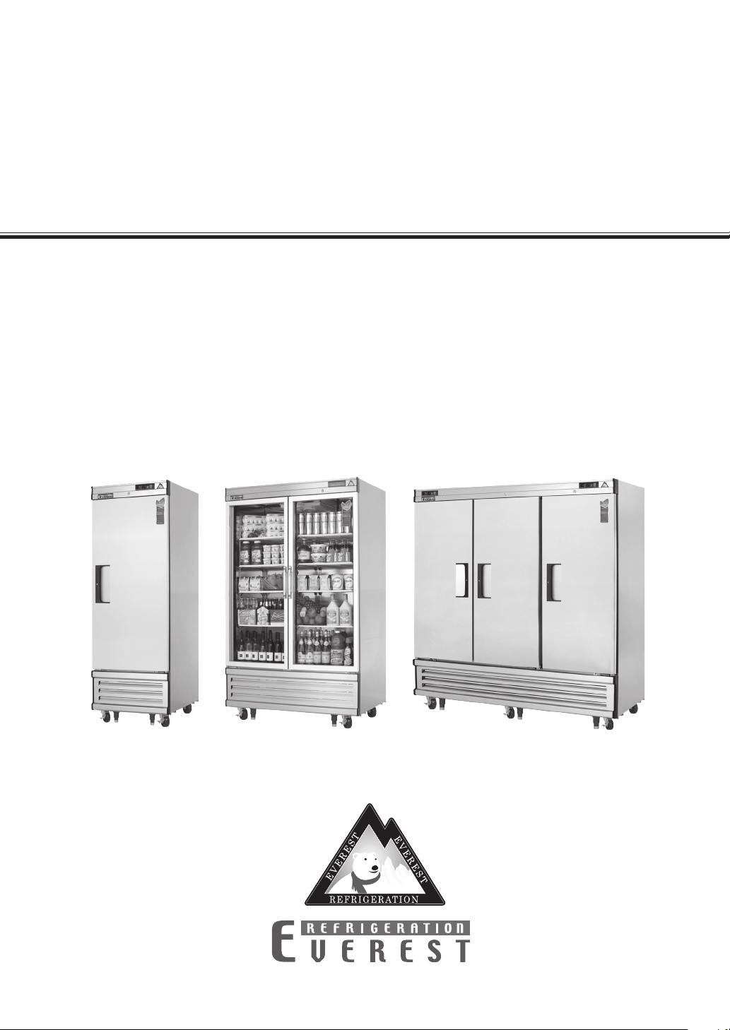
Upright Reach-Ins
Bottom Mounted Condensing Unit
Owner’s Manual
EBR1, EBWR1, EBWRH2, EBNR2, EBSR2, EBR2,
EBR3, EBR1D, EBNR2D, EBR2D, EBF1, EBWF1,
EBWFH2, EBNF2, EBSF2, EBF2, EBF3, EBF1D,
EBF2D, EBWRFH2, EBSRF2, EBRF2, EBRF2D,
EBRF3, EBGR1, EBGNR2, EBGR2
Page 2

this page intentionally left blank
Page 3
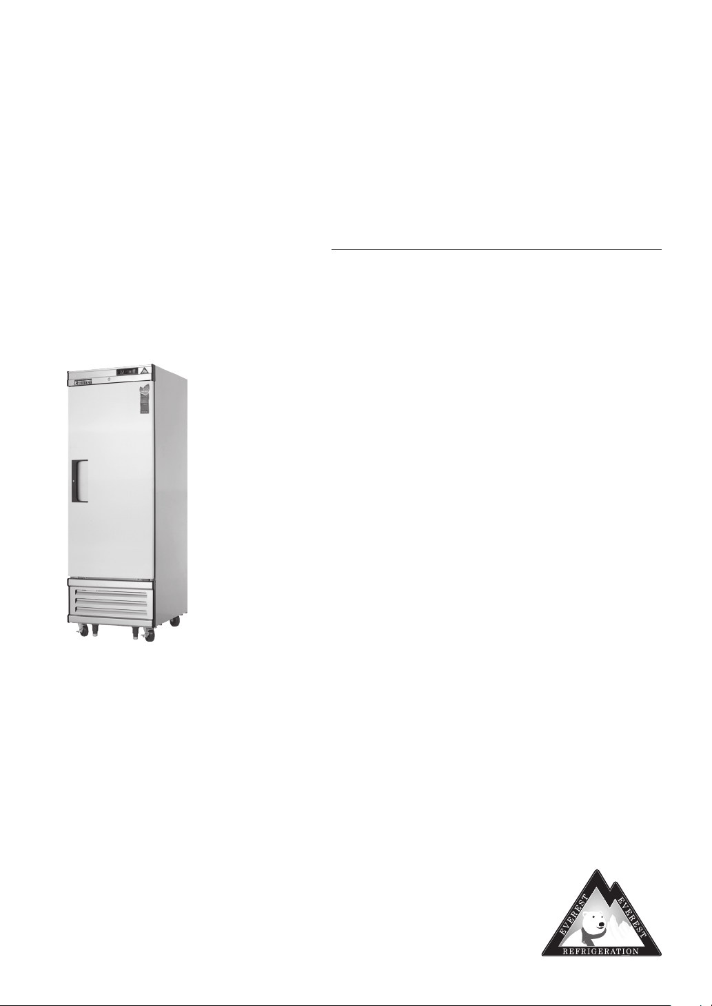
Upright Reach-Ins
Bottom Mounted Condensing Unit
EBR1, EBWR1, EBWRH2, EBNR2, EBSR2, EBR2, EBR3, EBR1D, EBNR2D, EBR2D, EBF1, EBWF1,
EBWFH2, EBNF2, EBSF2, EBF2, EBF3, EBF1D, EBF2D, EBWRFH2, EBSRF2, EBRF2, EBRF2D,
EBRF3, EBGR1, EBGNR2, EBGR2
Contents
Hydrocarbon Guidelines ............................. 1, 2
Installation Instructions ................................ 3, 5
General Safety ..................................................6
Electrical Safety ................................................7
Operation ................................................... 8–12
Care and Maintenance ............................ 13, 14
Door Reversal Instructions ...................... 15, 16
Troubleshooting Guide ............................. 17, 18
Warranty Information ............................... 19, 20
Everest Owner’s Manual
Page 4
Hydrocarbon Guidelines
This section applies to R290 Hydrocarbon units only. To identify the refrigerant type,
see the data plate in the cabinet interior.
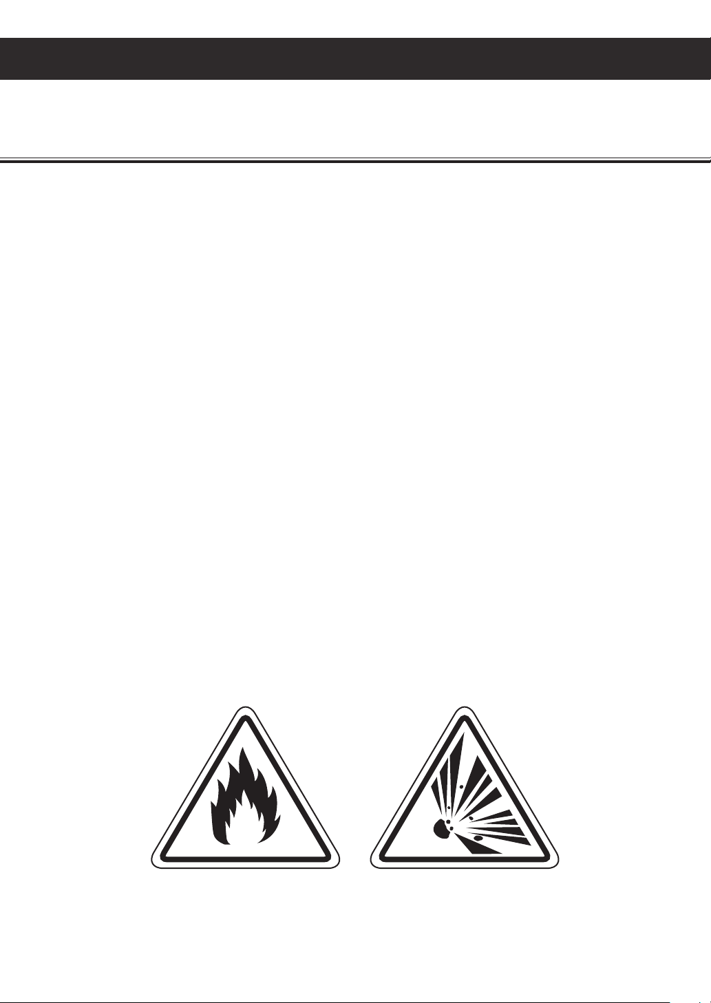
WARNING - THIS UNIT USES R290, A HYDROCARBON, PROPANE REFRIGERANT THAT IS
ENVIRONMENTALLY FRIENDLY BUT IS ALSO HIGHLY FLAMMABLE AND EXPLOSIVE. PLEASE
READ THIS MANUAL CAREFULLY AND FOLLOW ALL SAFETY PRECAUTIONS CONTAINED HEREIN
TO AVOID THE RISK OF FIRE OR EXPLOSION. FAILURE TO FOLLOW THE SAFETY PRECAUTIONS
MAY RESULT IN SERIOUS INJURY, OR DEATH, AND/OR PROPERTY DAMAGE.
DANGER - Risk of fire or explosion. Flammable refrigerant used. Do not use mechanical devices or
other means to accelerate the defrosting process. Do not puncture refrigerant tubing.
DANGER - Risk of fire or explosion. Flammable refrigerant used. To be repaired only by trained service
personnel. Do not puncture refrigerant tubing.
CAUTION - Risk of fire or explosion. Flammable refrigerant used. Consult Service Manual or Owner’s
Manual before attempting to install or service this product. All safety precautions must
be followed.
DANGER - Risk of fire or explosion. Dispose of properly in accordance with federal or local regulations.
Flammable refrigerant used.
DANGER - Risk of fire or explosion due to puncture of refrigerant tubing; follow handling instructions
carefully. Flammable refrigerant used.
1
Hydrocarbon Guidelines
Page 5

PROPANE (R290) IS HIGHLY APPROVED FOR USE AS A REFRIGERANT IN COMMERCIAL,
SELF-CONTAINED UNITS IN THE US UNDER LIMITED USE CONDITIONS. IT CAN ONLY BE
USED IN NEW EQUIPMENT. BACKFITTING OR MODIFICATIONS OF OLD EQUIPMENT ARE
NOT ALLOWED. IT MUST BE CHARGED IN A STRICTLY LIMITED VOLUME OF UP TO 150
GRAMS (5.3 OZ) PER REFRIGERATION CIRCUIT. EVEN THOUGH THIS IS A SMALL AMOUNT,
IT STILL PRESENTS A FIRE OR EXPLOSION HAZARD IF IT LEAKS OUT OF PARTS THAT
HOLD REFRIGERANT. WHEN IT COMES IN CONTACT WITH AIR, A FLAMMABLE PROPANE-AIR
MIXTURE CAN BE CREATED AND EASILY IGNITED BY ELECTRICAL SPARKS, OPEN FLAMES OR
HOT SURFACES. THE RISK IS HIGHER IN SMALL, CONFINED, POORLY VENTILATED SPACES.
PROPANE WILL SETTLE AT LOWER ZONES BECAUSE IT IS HEAVIER THAN AIR. TO REDUCE
THESE RISKS, OBSERVE THE FOLLOWING PRECAUTIONS
• Avoid installation of unit in areas with open flames or in general vicinity of open flames or high
surface temperatures.
• Avoid unit installation in small, confined spaces. Ensure ample ventilation at all times. Keep all
exhaust vents free of any blockage or obstruction.
• Do not rely on smell to detect potential leaks of propane refrigerant. Propane refrigerant is a
high purity propane gas and does not contain odorants or stenching agents. These additives are
typically used in fuel-grade propane and natural gas in order to give them a distinctive smell which
makes it easier to detect leaks.
• General service and repairs must be performed in well-ventilated areas.
• General service and repairs must be performed only by professionals authorized by Everest
Refrigeration.
• Component shall be replaced with Everest-issued, like components to minimize the risk of possible
ignition resulting from incompatible parts or improper repairs.
• Do not modify, re-appropriate, or remove any functional part(s) from the unit.
• Handle the unit with care to avoid any damage.
• Practice safety guidelines when transporting the unit. Consult with your local Department of
Transportation for requirements in moving flammable gasses.
Hydrocarbon Guidelines
2
Page 6
Installation Instructions
This section applies to all Everest products. Correct installation ensures proper performance
and longevity of your appliance. Professional installation by a trained refrigeration technician
and electrician is recommended. Warranty is void if the following guidelines are not met.
1. Inspect for any freight damage upon delivery
of the unit. If damage is detected, immediately
report it to an Everest representative. Everest
is not responsible for damage that occurs
during shipment.
2. Keep the unit upright at all times. The
compressor contains oil, refrigerant,
lubricants, and various chemicals. When tilted,
these fluids may shift and travel to sections
where they don’t naturally occur. This will
lead to system contamination and compressor
failure.
3. Some units require caster installation for
proper performance. Visit our website at
www.everestref.com and enter your product’s
model number in the search field to determine
its caster requirements.
4. Do not place your hands under the unit when
moving it to avoid injury from sharp edges,
protruding parts or weight impact.
5. Select a location with good air ventilation.
Poor ventilation rapidly increases ambient
temperature. High ambient temperatures
exceeding 86°F (30°C) promote excessive
compressor activity in order to maintain the
desired cabinet temperature. This will result in
decreased performance, advanced component
failure and the risk of fire.
6. Select a location away from heat-generating
equipment such as stoves, ovens, etc. Heat
sources rapidly increase the temperature of
the immediate vicinity. High temperatures
exceeding 86°F (30°C) promote excessive
compressor activity in order to maintain the
desired cabinet temperature. This will result in
decreased performance, advanced component
failure, and the risk of fire.
8. Select a location with a hard, leveled surface.
Use a leveling tool on the unit to ensure proper
alignment. Proper door function and condensate
removal is dependent on accurate balance.
Install the front leg stabilizers for units that
come standard with it to ensure proper door
functions and unit stability.
9. Select a location close to an electrical wall
outlet to ensure direct connection without the
use of extension cords.
10. Select a location away from severe moisture
conditions. This may compromise the unit’s
electrical components and lead to electrical
shocks or the risk of fire.
11. Select a location that will not expose the unit
to extremely dusty conditions. Environments
with high dust and debris content will
significantly hasten condenser coil blockage
and will result in decreased performance,
advanced component failure and the risk of fire.
12. Do not build an enclosure or cabinet around
the unit. This will restrict air ventilation
resulting in elevated compressor activity,
decreased performance, advanced component
failure and the risk of fire.
13. The unit is not intended for use in food trucks.
Limited space, lack of ventilation, and ambient
temperatures exceeding 86°F (30°C) typical to
this setting will result in elevated compressor
activity, decreased performance, advanced
component failure, and the risk of fire.
14. The unit is intended for indoor use only.
Outdoor use will cause a decrease in
performance, advanced component failure and
the risk of fire.
7. A distance of 6" is required for backside
clearance. This ensures proper ventilation
and prevents overheating which can lead
to advanced component failure and the risk
of fire.
3
Installation Instructions
Page 7
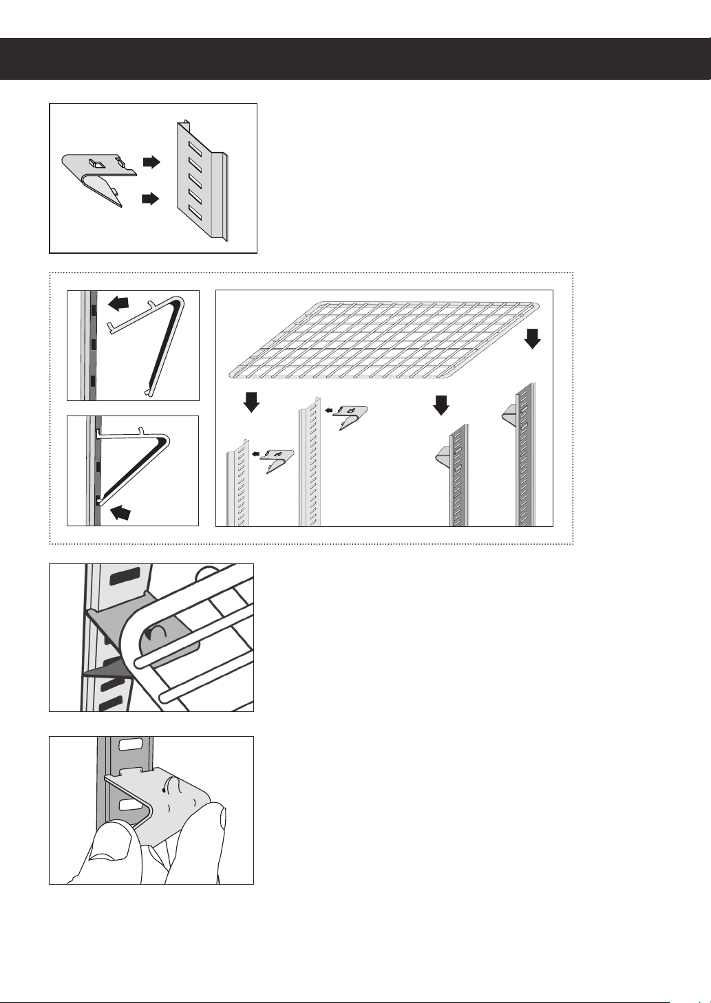
Shelf Installation
1. Attach the shelf clips onto the pilasters by inserting its
top hook into a pilaster notch followed by the bottom
hook. Do not use pliers or other crimping tools to
modify the shape of the shelf clips. This will result in
shelf mounting instability.
Installation Instructions
2. Place shelves on the shelf clips making sure all
corners are mounted securely and evenly with identical
distance from the unit’s floor and up. Always lay the
back of each shelf down on the rear clips before the
front.
3. When removing a shelf, unmount the shelf from the
shelf clips. To detach the shelf clip from the pilaster,
tilt up the shelf clip until the bottom hook clears,
followed by the top hook.
4
Page 8
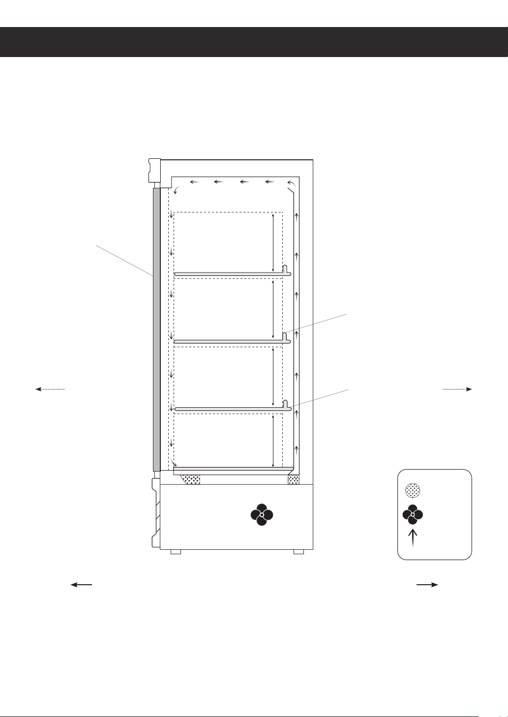
Product Load Level & Shelf Placement
Product Load Level for EB
Solid Door
Front Rear
Load Level 12"
Load Level 12"
Load Level 12"
Load Level 12"
Airflow Guard
Shelf
Air Vent
Fan
Air Flow
Front Rear
Side View
5
Installation Instructions
Page 9
General Safety
This section applies to all Everest products. Use your appliance according to its designed
function as specified in this Owner’s Manual. Warranty is void if the following guidelines
are not met.
• Before the unit is used, it must be installed and connected according to the installation instructions
provided in this manual.
• Remove all packaging material and protective vinyl covering from the unit before it is used.
These items are flammable and can lead to a fire.
• Do not store or use gasoline or other flammable vapors and liquids in the vicinity of the unit.
Do not store combustible or explosive items and substances such as aerosol cans in or around
the vicinity of the unit.
• Do not place objects on or around the exhaust vents of the unit. This can cause overheating
which may lead to a fire or explosion. Objects may also fall when opening and closing doors
which may lead to serious injury.
• Do not climb, stand, or hang on the shelves, doors or drawers of the unit. This can damage the unit
and lead to serious injury.
• Do not touch the freezer interior if your hands are wet or damp. This may lead to freezer burn or
cause your skin to stick to the cold surface.
• If you suspect a refrigerant leak or a compromised refrigeration system, disconnect the unit,
and contact Everest Refrigeration immediately.
• When disposing the unit, remove all doors and shelves to avoid any risk of injury or entrapment.
Ensure that the refrigerant in the condensing unit is properly disposed of by a qualified refrigeration
technician according to governmental codes, requirements and regulations.
General Safety
6
Page 10
Electrical Safety
This section applies to all Everest products. Basic safety precautions must be observed when
using electrical appliances in addition to the following. Warranty is void if these guidelines
are not met.
Everest units come as 115 volts, 60 hertz,
single phase.
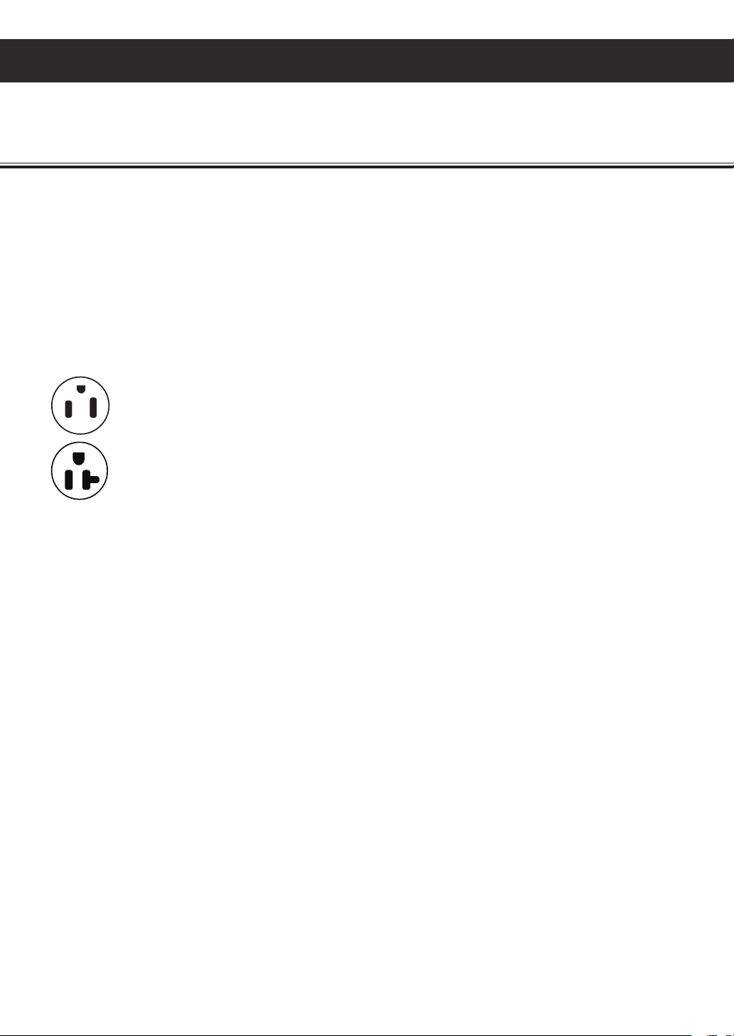
Everest units are equipped with a NEMA 5-15P
plug except for models ESF2, ESWF2, ESF3 and
EBF3 which are equipped with a NEMA 5-20P. A
15 amp breaker must be used for units that come
with a NEMA 5-15P plug. A 20 amp breaker must
be used for units that come with a NEMA 5-20P
plug.
115/60/1
NEMA 5-15R
115/60 /1
NEMA 5-20R
The ground prong must not be removed to reduce
the risk of electric shock and related hazards.
If the grounding pin is missing, the cord must
be removed from use. If the outlet is a standard
2-prong outlet, it must be replaced with the
properly grounded 3-prong wall outlet. Only
a qualified electrician may install the correct
power source.
Do not use extension cords, adapter plugs or
other third party electrical connections. Everest is
not responsible for issues resulting from improper
electrical connections, electrical power failures
and voltage fluctuations.
Everest does not recommend the use of
generators in conjunction with the unit due
to voltage fluctuations that may compromise
electrical components.
Turn off the unit using the power button before
unplugging. Wait at least 5 minutes before
re-plugging to prevent damage to the compressor.
Do not unplug the unit by tugging on the power
cord. Grip the plug and pull it securely out of the
outlet.
Prevent damage to the power cord by providing
sufficient clearance around and under the unit.
Do not use a power cord that shows cracks or
exposed wires. Power cords that have been
severely worn or damaged must be replaced
with original manufacturer parts and only by
an authorized technician.
To guarantee electrical safety, the wall outlet and
circuit must be checked by a qualified electrician
to make sure it is properly grounded.
Remove debris from the power plug prongs
with a soft cloth or brush before connecting
it to an outlet.
Assign the unit to a dedicated, undamaged
electrical circuit with a voltage rating that
matches the data plate. Check the incoming
voltage with a multi-meter. This avoids the
overloading and overheating of circuit wires
which may lead to a fire.
7
Electrical Safety
Page 11
Operation
This section applies to all Everest products. Use according to the described and intended
functions. Warranty is void if these guidelines are not met.
Starting your Everest Product
After plugging in the unit, the current temperature and compressor symbol will appear on the
digital temperature control’s LED display. will flash at short intervals for 1 minute after which the
compressor(s) and condenser fan motor(s) will initiate. At the beginning of every compressor cycle,
the condenser fan motor is automated to rotate in reverse for 30 seconds in order to blow dust off the
condenser coil.
The evaporator fan motor(s) will initiate once the evaporator coil reaches a specific temperature
relative to the digital temperature control setting and for as long as the door is closed. A fan symbol
will appear on the LED display to indicate that the evaporator fan is running.
Allow the unit to operate for 24 to 72 hours before storing contents in the cabinet. This lets the cabinet
temperature fully stabilize. Use this time to verify proper installation and operation.
The interior light and evaporator fan motor is controlled by a door switch for solid door models and a
rocker switch for glass door models.
The default temperature setting is 35.0°F (2.0°C) for refrigerators and -4.0°F (-20.0°C) for freezers.
The factory recommended temperature range is between 33.0°F (1.0°C) to 40.0°F (4.0°C) for
refrigerators and -5.0°F (-21.0°C) to 0°F (-18.0°C) for freezers. Setting the temperature outside of the
recommended range will cause performance issues and in some cases may result in component failure
that is outside of warranty coverage.
The compressor, condenser and evaporator fan motors run while the unit is on refrigeration cycle.
The compressor, condenser and evaporator fan motors stop running while the unit is on defrost cycle.
The unit is preset to defrost every 5-6 hours with a duration of 45 minutes or less depending on the
evaporator coil temperature. Changing the preset outside of the default range will result in cooling
issues and advanced component failure.
The digital temperature control is intended to read and display the cabinet’s air temperature, not actual
food product temperature. The displayed temperature may fluctuate due to frequent or prolonged door
operation. The most conclusive method to determine a unit’s cooling performance is to measure the
food product’s temperature using a digital food thermometer.
Operation
8
Page 12
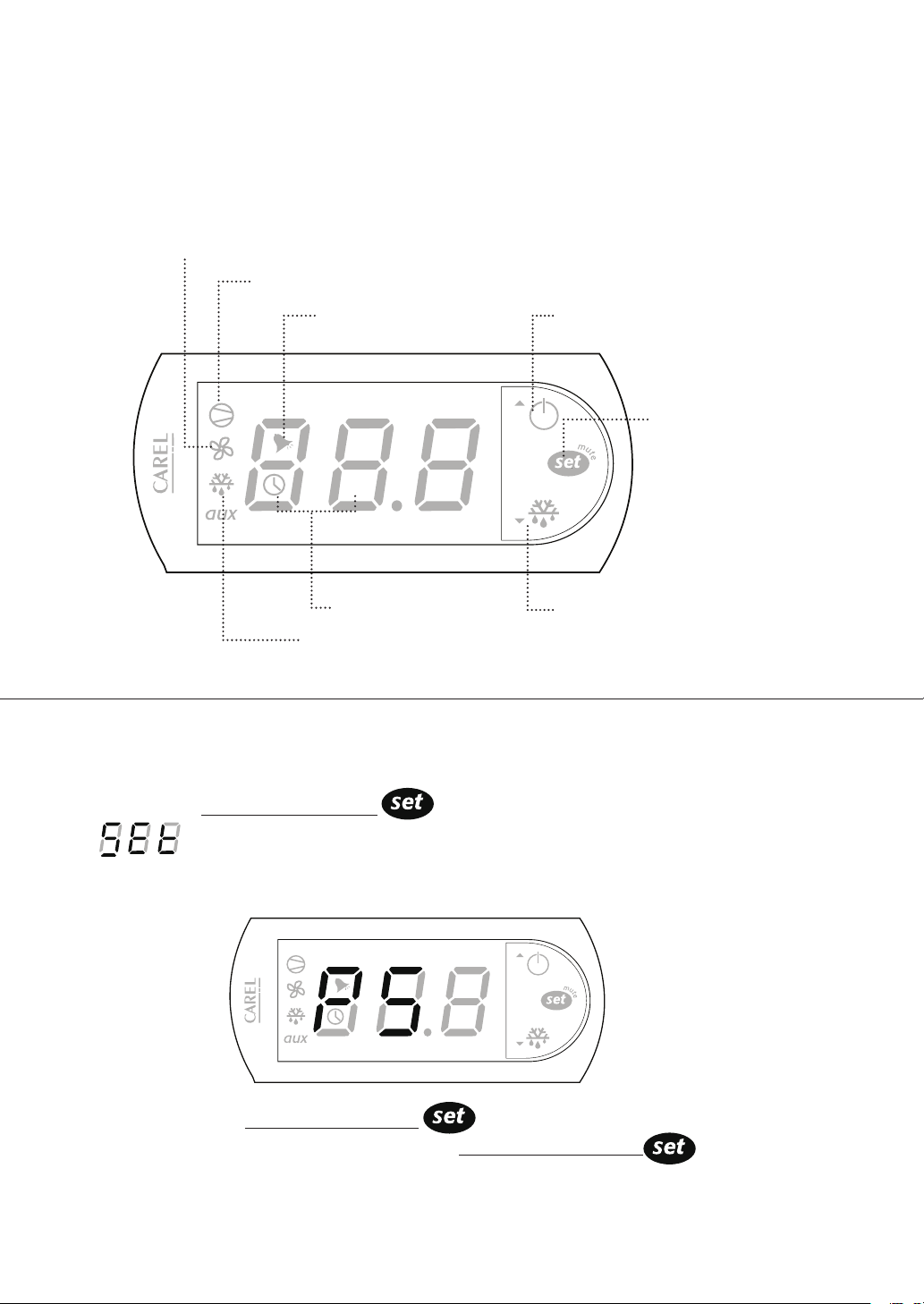
Carel ‘Easy’ Digital Temperature Control
Everest units are equipped with a Carel Digital Temperature Control. The type of controller is
dependent on the model and production date.
Evaporator Fan Running
Compressor Running
Alarm in Progress
Cabinet Temperature
Cabinet in Defrost
Setting the Temperature
1. Press and hold Temperature Set Button for 2 seconds until the LED blinks
SET alternating with a number. The blinking number is the current set temperature.
Power / Up Button
Temperature
Set Button
Manual Defrost / Down Button
CAUTION: If PS appears on the LED
This means the Temperature Set button was held down longer than 3
seconds. To exit this mode and restart, press Temperature Set Button
9
Operation Guidelines
Page 13

Setting the Temperature ( continued )
2. Toggle through the desired temperature by pressing UP or DOWN The number increases
or decreases by a decimal point.
3. The recommended setting is 35.0°F (2.0°C) for refrigerators and -4.0°F (-20.0°C) for freezers. The
available temperature setting range is 33.0°F to 54.0°F (1.0°C to 12.0°C) for Refrigerators and -10.0°F to
54.0°F (-23.0°C to 12.0°C) for Freezers.
4. Press and hold the Temperature Set Button for 3 seconds to save the new temperature and exit
the setting mode. The LED will return to the current cabinet temperature.
Initiating Manual Defrost
The controller has an automatic defrost cycle in place so initiating manual defrost is not
necessary unless there is an abnormal accumulation of ice around the evaporator coil.
1. Press and hold down the Manual Defrost Button until the Defrost Symbol
appears on the LED display.
The compressor, condenser and evaporator fan motors will stop running.
The refrigeration system will remain in defrost cycle for 45 minutes or until the
evaporator coil reaches the safety termination temperature setting.
Operation Guidelines
10
Page 14
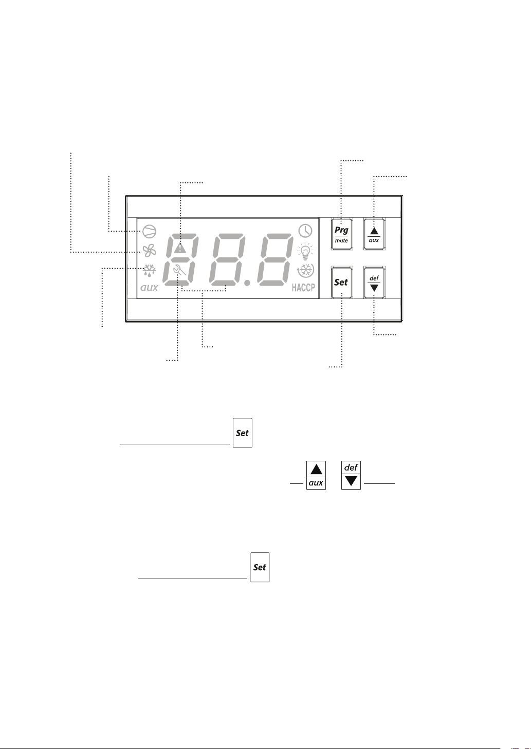
Carel ‘ir33’ Digital Temperature Control
Everest units are equipped with a Carel Digital Temperature Control. The type of controller is
dependent on the model and production date.
Evaporator Fan Running
Compressor Running
Alarm in Progress
Program Button
Up Button /
Auxiliary
Cabinet in Defrost
Cabinet Temperature
Error
Setting the Temperature
1. Press and hold Temperature Set Button for 2 seconds until a number blinks on the LED.
The blinking number is the current set temperature.
2. Toggle through the desired temperature by pressing UP or DOWN. The number
increases or decreases by a decimal point.
3. The recommended setting is 35.0°F (2.0°C) for refrigerators and -4.0°F (-20.0°C) for freezers.
The available temperature setting range is 33.0°F to 54.0°F (1.0°C to 12.0°C) for Refrigerators
and -10.0°F to 54.0°F (-23.0°C to 12.0°C) for Freezers.
4. Press and hold the Temperature Set Button for 3 seconds to save the new temperature
and exit the setting mode. The LED will return to the current cabinet temperature.
Temperature Set Button
Down Button /
Manual Defrost
11
Operation Guidelines
Page 15
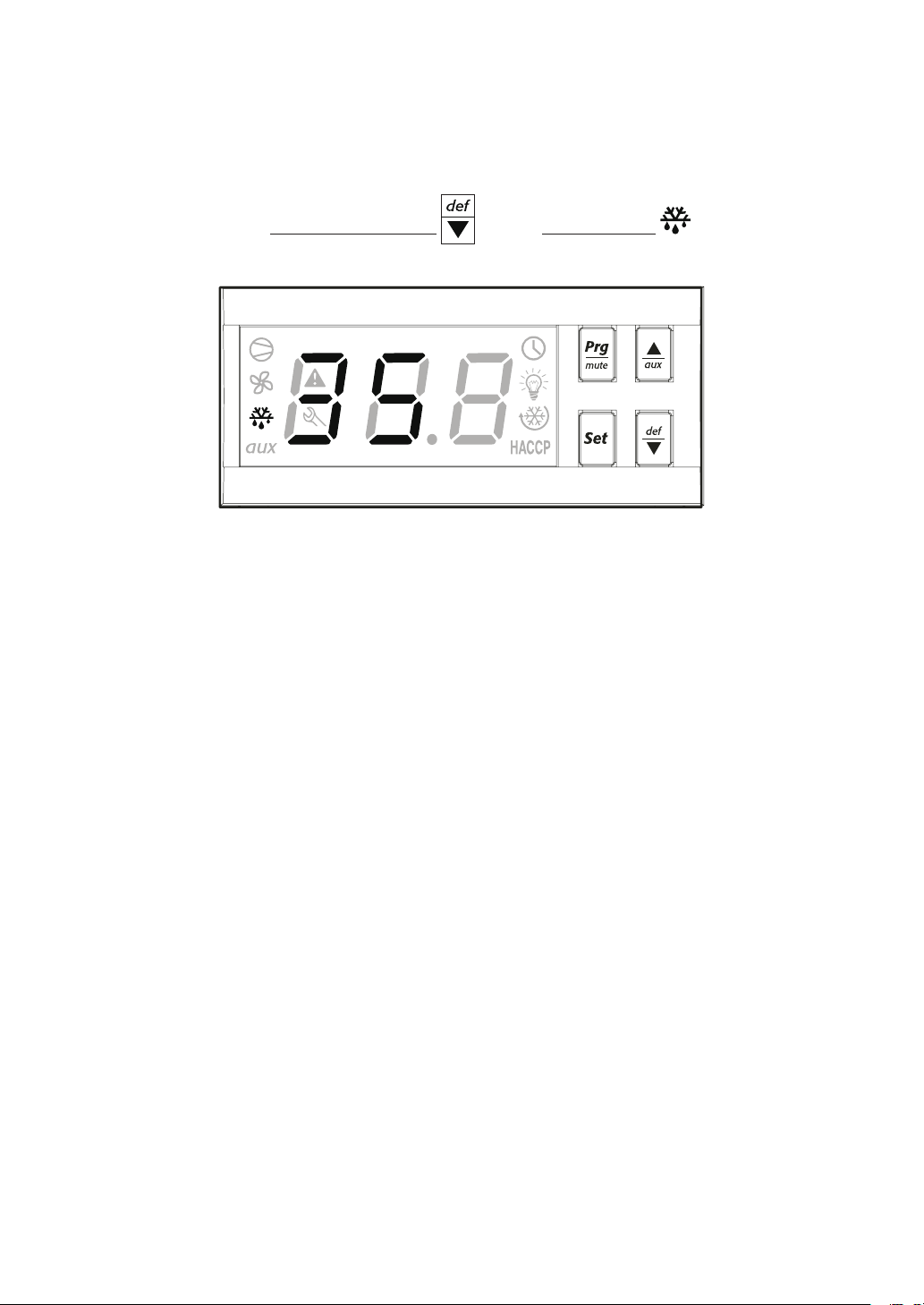
Initiating Manual Defrost
The controller has an automatic defrost cycle in place so initiating manual defrost is not necessary
unless there is an abnormal accumulation of ice around the evaporator coil.
1. Press and hold down the Manual Defrost Button until the Defrost Symbol appears on the LED
display.
The compressor, condenser and evaporator fan motors will stop running. The refrigeration system
will remain in defrost cycle for 45 minutes or until the evaporator coil reaches the safety termination
temperature setting.
Operation Guidelines
12
Page 16
Care and Maintenance
This section applies to all Everest products. Regular care and maintenance of your appliance
will significantly extend service life and dependability. In severe cases, lack of upkeep will
contribute to the rapid decline in performance and component health. Care and maintenance is
the product owner’s personal responsibility. Warranty is void if these guidelines are not met.
• Unplug the unit before cleaning, repairing or replacing parts.
• Do not spray the unit with water to avoid electric shock, component malfunction or the risk of fire.
• Do not use any flammable cleaning products on or around the unit to prevent the risk of fire.
• Do not use household or industrial chemical cleaners, acidic or chlorine based solutions,
degreasers, wire brushes, scrapers, steel pads, acidic solutions, or other abrasive products.
These will damage the stainless steel’s passivity layer resulting in advanced corrosion.
• The condenser coil and condenser coil air filter build up lint, dust and grease over time and will
require monthly cleaning. Clogged condenser coil and filters will result in decreased performance,
advanced component failure, and a risk of fire. See page 14 for condenser coil and filter cleaning
instructions.
• Conduct regular inspection and cleaning of the door gaskets to ensure that they are sealing
completely. Worn out or damaged gaskets will have gaps that will compromise cabinet temperature
leading to possible food spoilage or component failure.
• Clean the interior surface of the unit with mild soap and warm water. Do not let water accumulate
inside the unit. To prevent water damage, wipe the interior of the unit with a dry cloth as needed.
Do not use steel wool, strong acids, concentrated detergents, bleaches, cleaning waxes, polishers
and other abrasive cleaners. Avoid contact with electronic parts to avoid the risk of fire.
• Clean the exterior of the product with a stainless steel cleaner to restore the condition and
passivation of the stainless steel surface. Do not use steel wool, strong acids, concentrated
detergents, bleaches, cleaning waxes, polishers and other abrasive cleaners. Avoid contact with
electronic parts to avoid the risk of fire.
• Acidic products and products containing vinegar must be stored in sealed containers to prevent acid
damage to the interior of the unit and the evaporator coil. Rust resulting from improper maintenance
is not covered under warranty.
13
Care and Maintenance
Page 17
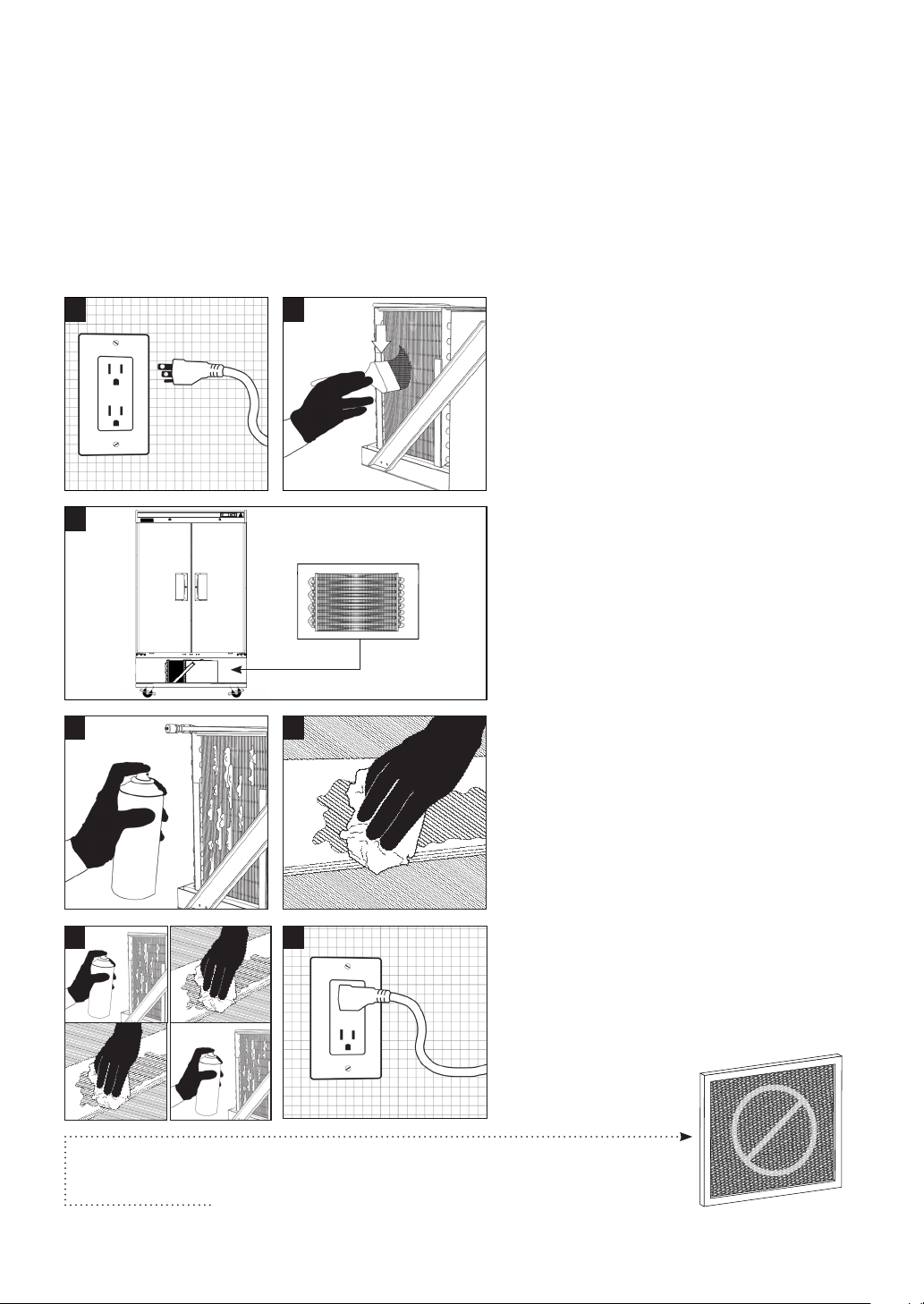
Condenser Coil Cleaning Instructions
* R404A freezer models are equipped with a condenser coil air filter. R290 refrigerator models are not equipped with a condenser
coil air filter. If your product is an R290 refrigerator model, you may skip this section.
This section applies to all Everest products. The condenser coil requires monthly cleaning to keep
the metal fins clear of lint, dust and grease build-up. A clogged condenser coil severely reduces your
product’s energy efficiency and places strain on the compressor and other components leading to
advanced failure. Cleaning the condenser coil is the product owner’s personal responsibility.
Warranty is void if the following guidelines are not met.
1
2
1. Ensure that the unit is disconnected from
the outlet before performing maintenance.
2. Use a long bristled brush in a vertical
sweeping motion to remove lint, dust and
debris from in between the metal fins of
the condenser coil. Do not apply heavy
pressure so as not to bend the fins.
3
3. Locate the condenser coil at the bottom
section of the unit. Some frames do not
have panels for ease of access and
ventilation purposes.
4
6
5
7
4. Use a commercial condenser coil cleaner
for metal fins that are coated in grease.
Allow the cleaner to saturate the area.
Follow the recommended wait time
printed on the product packaging.
5. The grease and cleaning solvent will
pool at the base of the metal fins. Brush
the fins and wipe off any accumulated
residue.
6. Repeat the above steps until the metal
fins are clean. You should be able to see
in through and in between the metal fins.
7. Reconnect the unit to the specified outlet.
Do not attach an aftermarket filter or screen around the condenser coil.
This constricts ventilation which leads to overheating, component failure
or the risk of fire.
Care and Maintenance
14
Page 18
Door Reversal Instructions
Some products have field reversible doors to accommodate specific kitchen layouts. Door
reversals must be performed by qualified technicians. A second person is required. Safety
goggles must be worn to protect from spinning parts. Warranty is void if the following
guidelines are not met.
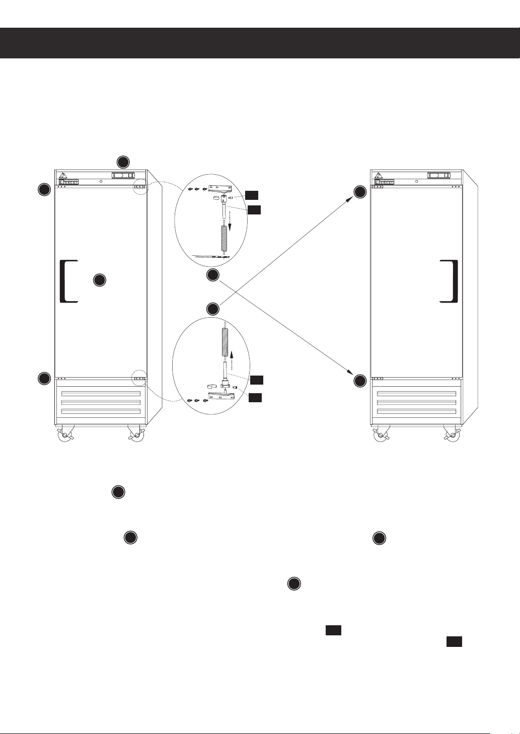
A
MANUFACTURINGMANUFACTURING
B
C-2 :Lock Screw
C-1 :Right Top
Hinge Shaft
D
E
B
[BEFORE]
C
D
D-1 :Right Bottom
Hinge Shaft
D-2 :Lock Screw
C
[AFTER]
1. The front grill A must be opened before reversing the door. Grab the left and right bottom corner
of the front grill and pull it towards you. Slightly lift up the front grill until it’s top hooks unlock from
the frame.
2. Locate 3 screws B on the top left corner of the door frame and 3 screws B on the bottom left
corner of the door frame. Remove these screws from the pre-drilled holes. They will be used to
mount the door to the left door frame later.
3. Locate the door switch tab on the top right door frame F. The tab is positioned to press on the
door switch that controls the interior lights and evaporator fans. Once the door is reversed, the tab
must be moved to the same location.
4. Locate the door spring shaft on the top right corner of the door
4 screw holes, one of which is occupied by a lock screw that maintains door spring tension
. The head of the shaft has
C- 1
C- 2
Remove the half ring shaft cap to expose the remaining vacant screw holes.
15
Door Reversal Instructions
.
Page 19

Door Reversal Instructions (Continued)
5. Extra precaution must be taken for the following steps. Release the door tension from the door
spring by inserting a sharp pointed implement into one of the door hinge shaft’s unoccupied
tension lock screws
6. Slowly turn the door spring shaft clockwise until you are able to unscrew the tension lock
C- 2
screw
7. Slowly take out the sharp pointed implement inserted into one of the spring shaft’s unoccupied
tension lock screw holes. When the rigid object clears the hole, the door spring will release the
stored tension and the door spring shaft will spin rapidly.
8. Follow steps 4 through 7 for the bottom door shaft.
9. A second person is required to secure the door against the unit while the top hinge is removed E.
10. Detach the top hinge by removing the 3 screws holding it in place C.
11. Lift the door until it detaches from the bottom hinge D. Ensure that the top and bottom springs and
shafts remain in the door cavity.
12. Detach the bottom hinge by removing the 3 screws holding it in place C . Detach the bottom hinge.
13. The right top hinge becomes the left bottom hinge C. Install the right top hinge into the left bottom
position using 3 screws. Ensure that the door hinge pins are facing up.
. Remove the tension lock screw.
C- 2
.
14. Flip the door so that the hinged corners are on the left side when facing the door E.
15. Mount the door on the bottom door hinge C. The longer of the two pins pointing upward should be
inserted into the bottom spring shaft.
16. A second person is required to secure and hold the door against the unit while the top hinge is
installed E .
1 7. TThe bottom right hinge becomes the left top hinge D. Install the left top hinge on the door. The
two pins on the door hinge should be facing down and the longer of the two inserted into the top
door spring shaft.
18. Secure the top hinge to the unit using 3 screws. Ensure that the door is properly secured to
the frame.
19. Sufficient tension must be added to the door springs so that it self-closes. Insert 2 sharp pointed
implements into the vacant tension lock screw holes (
2 to 3 rotations should provide sufficient tension.
20. Test the door for proper operation.
C- 1
,
) and turn the shaft counterclockwise.
D- 1
Door Reversal Instructions
16
Page 20
Troubleshooting Guide
In most cases, your Everest product may be exhibiting behavior that is typical
of standard operation. Observe the following when troubleshooting symptoms.
‘cht’ or ‘CHt’ appears on the LED alternating
with the current temperature and accompanied
by an audible alarm.
The condenser coil may be clogged with dust,
grime or debris. Clean it following the instructions
on page 14.
The room’s ambient temperature may be higher
than 86°F (30°C). Provide ample ventilation or
additional cooling to the room or relocate the unit
to a larger space with lower ambient temperature.
The unit may be installed in close proximity to
heat sources such as ovens, stoves, heaters or
direct sunlight. Relocate the unit away from these
sources.
The unit may be installed without clearance or
proper ventilation. Provide additional exhaust
vents and observe the clearance allowance
specified on page 3.
The compressor, fan motors or entire system
fails to start
The ON/OFF switch may be set to OFF. Turn to
the ON position and wait for the LED and motors
to show signs of operation.
The compressor operates continuously or for
prolonged periods.
The condenser coil may be clogged with dust,
grime or debris. Clean it following the instructions
on page 14.
The door or door gaskets may not be sealing
properly. Check if the unit is properly leveled as
this will affect the door’s self-closing mechanism.
Check product placement in the cabinet as it may
prevent the door from fully closing. If the gasket is
loose, reattach.
The evaporator coil may be blocked with ice.
Defrost it following the instructions on page 14.
Normally, evaporator coils will self-maintain with
automated defrost cycles. If the evaporator coil
ices up frequently, re-assess placement of food
items in the cabinet as it could obstruct cold
air circulation. Food items must not touch the
wall or floors of the cabinet and stay within the
boundaries of the shelf to prevent blockage of
air flow.
The room’s ambient temperature may be higher
than 86°F (30°C). Provide ample ventilation or
additional cooling to the room or relocate the unit
to a larger space with lower ambient temperature.
The power cord may not be connected. Check
for proper connection. In cases of damage to the
power cord or plug, immediately mark the unit as
out of order until the damaged part is replaced.
The outlet may not be sending power or the
power supply breaker may be switched off. Unplug
the unit and contact a licensed electrician for
inspection and/or repairs.
17
The unit may be installed in close proximity to
heat sources such as ovens, stoves, heaters or
direct sunlight. Relocate the unit away from these
sources.
The unit may be installed without clearance or
proper ventilation. This forces the compressor to
operate constantly in order to maintain cabinet
temperature. Provide additional exhaust vents
and observe the clearance allowance specified
on page 3.
Troubleshooting Guide
Page 21

The cabinet temperature is too warm.
Condensation in the interior cabinet.
The condenser coil may be clogged with dust,
grime or debris. Clean it following the instructions
on page 14.
The door or door gaskets may not be sealing
properly. Check if the unit is properly leveled as
this will affect the door’s self-closing mechanism.
Check product placement in the cabinet as it may
prevent the door from fully closing. If the gasket
is loose, reattach.
The temperature may be set too high. Adjust the
setting to 35.0°F (2.0°C) for refrigerators or
-4.0°F (-20.0°C) for freezers.
Hot food items may have been placed in the
cabinet. Store only room temperature food items.
The room’s ambient temperature may be higher
than 86°F (30°C). Provide ample ventilation or
additional cooling to the room or relocate the unit
to a larger space with lower ambient temperature.
The unit may be installed in close proximity to
heat sources such as ovens, stoves, heaters,
or direct sunlight. Relocate the unit away from
these sources.
The unit may be installed without clearance or
proper ventilation. Provide additional exhaust
vents and observe the clearance allowance
specified on page 3.
The door or door gasket may not be sealing
properly. Check product placement in the cabinet
as it may prevent the door from fully closing.
Check if the unit is properly leveled. If the gasket
is loose, reattach.
Hot food items may have been stored in the
cabinet. The interaction between hot and cold
temperatures will promote condensation.
Unsealed or open food items with high moisture
content may have been stored in the cabinet.
Keep these items in air tight containers.
Mild condensation in warmer ambient temperature conditions may occur due to frequent
or prolonged door operation.
Condensation on the unit’s exterior surfaces.
Highly humid environments will contribute to
the condensation build up on exterior panels.
Providing ample ventilation and air movement
to a space will reduce the humidity level.
The door or door gasket may not be sealing
properly. Check product placement in the cabinet
as it may prevent the door from fully closing.
Check if the unit is properly leveled. If the gasket
is loose, reattach.
Noise level during unit operation.
Food items are frosting over.
The temperature may be set too low. Adjust the
setting to 35.0°F (2.0°C) for refrigerators or
-4.0°F (-20.0°C) for freezers.
The placement of food items in the cabinet may
be obstructing circulation of refrigerated air. This
creates uneven temperature in the cabinet with
pockets of very cold air that may cause items to
frost or freeze over. Food items must not touch
the wall or floors of the cabinet and stay within
the boundaries of the shelf to prevent blockage
of air flow.
Troubleshooting Guide
It is normal for commercial grade compressors
and components to have a higher decibel output
compared to residential counterparts.
The unit may not be balanced evenly. Poorly
leveled units may cause components or fittings
to misalign or disengage during operation. This
may produce noise as a direct result of repeated
surface friction or impact.
The unit may not be securely mounted to the
floor. This may produce noise as a direct result
of repeated surface friction or impact.
Some sounds are normal for the refrigeration
process. A dripping sound, for example, is the
result of refrigerant circulation during the
compressor rest period.
18
Page 22

Warranty Registration
Registering your new appliance is important. In the unlikely event a safety notification or
warranty service is required, we will have the means to contact you. Your completed appliance
registration also verifies your ownership in the event of an insurance loss or theft.
You may register online at www.EVERESTref.com or use your smart phone to scan the QR code below:
1. Open the camera app.
2. Point the camera at the QR code.
3. Scan and launch the QR code.
Product Identification:
The product data plate is a permanently affixed label that contains the model, serial, barcode numbers,
and refrigeration data of your Everest product. The tag is located on the rear or side of the unit exterior.
Please retain this information for warranty-related purposes.
19
MODEL : ESR1
COMPRESSOR : 1/2 HP
REFRIGERANT : R290
* Use of other than specified refrigerant voids warranty
REFRIGERANT CHARGE : 3.17 Oz
ELECTRICAL :
TOTAL AMPS : 3.27A (COMP RUN)
HIGH PRESSURE TEST : 218PSIG.
LOW PRESSURE TEST : 38PSIG.
* Do not clean label with solvent
EOMV-36-B-28-S
115VX1Phx60Hz
EOMV-36-B-28-S-XXX
Warranty
Page 23
Warranty Certificate
3
YEAR S
PARTS & LABOR
YEAR S
ELECTRICAL
10
YEAR S
COMPRESSOR
20
Page 24
A Step Above The Standard
201 W. Artesia Blvd., Compton, CA 90220
Tel: 800-444-6285 / 310-323-6586
Fax: 310-323-7524 / 310-761-1127
www.EVERESTref.com
v101722
 Loading...