

Everdure CBGS62 Installation Manual
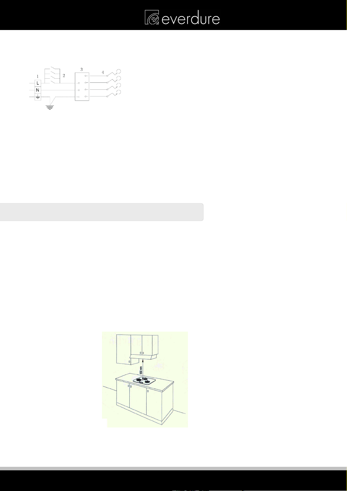
—connect the blue wire to the terminal marked with the letter N or coloured black;
—connect the brown wire to the terminal marked with the letter L or coloured red.
After having installed the appliance, the power switch or power plug must always be in an accessible position.
Electrical connection diagram
N.B For connections to the mains power supply, never use adapters, reductions or multiple power points as
these may overheat and catch fire.
In the event that installation should require modifications to the mains supply wiring system or if the power plug
is not suitable for the type of power point available, it is required that a qualified technician be called to carry
out substitution.
The technician will also have to verify that the cross-section of the electric cables on the power point match the
appliance’s power rating.
INSTALLATION
Note: These tops are designed to be fitted into kitchen fixtures measuring 600 mm in depth.
In order to install the cooker top into the kitchen fixture, a hole with the dimensions shown on the cutting size
board has to be made, keeping in consideration the following:
Within the fixture, between the bottom side of the cooker top and the upper surface of any other appliance or
internal shelf there must be a clearance of at least 30 mm;
Keep at least 200mm from the periphery of the burners to any side or rear wall.
There must be a distance of at least 650 mm between the hob and any extractor hood positioned immediately
above it, or 800mm between the hob and any wall cupboard.
It is essential to install a heat baffle between the bottom of the hob and the underlying unit.
Note: Keep a safe distance away from combustible constructions.
8
DESIGNED TO PERFECTION
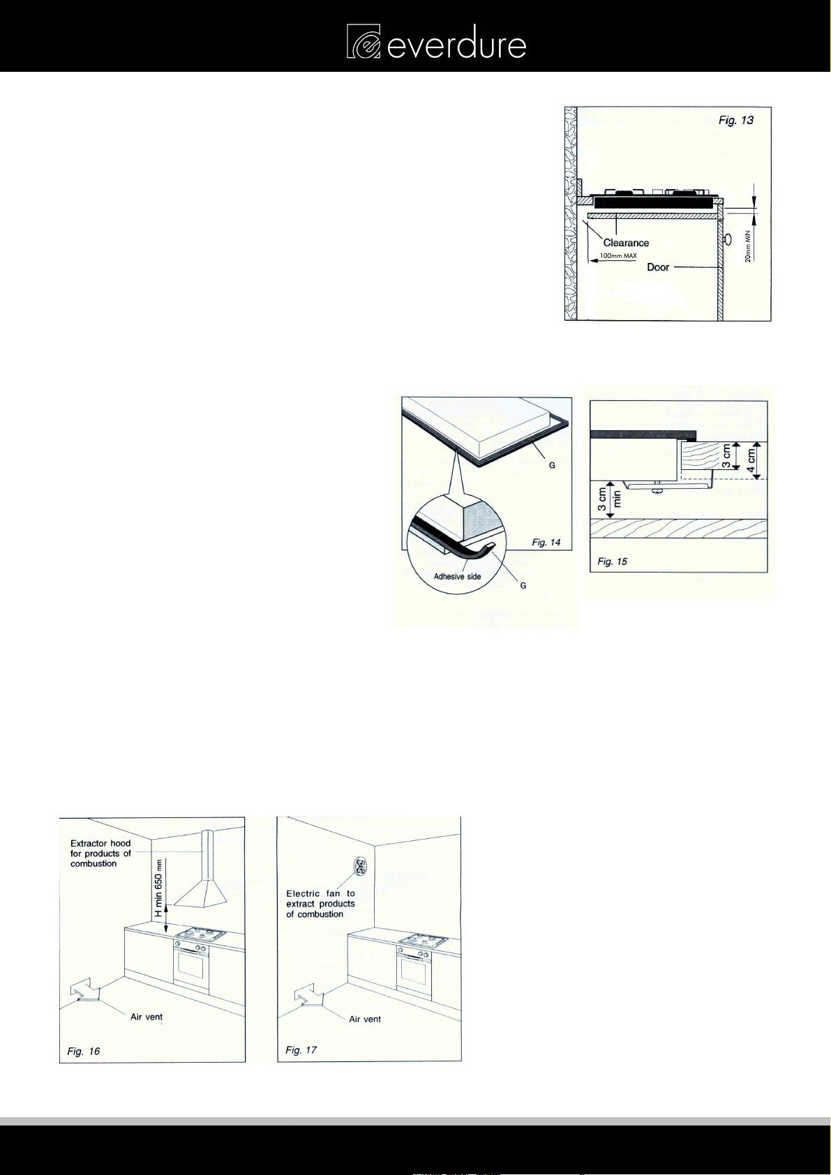
INSTALLATION IN KITCHEN CABINET WITH DOOR
The fixture has to be made according to specific requirements in order to
prevent the gas burners from going out, even when the flame is turned
down to minimum, due to pressure changes while opening or closing the
cupboard doors.
When the hob is installed above a cupboard with doors, a separate panel
must be installed underneath it. Leave a gap of at least 20 mm clearance
between the cooker top and the surface of the panel (fig.13), which must
be easily removable to allow sufficient access for any servicing procedures.
NOTE: When installing above a cupboard, a dividing shelf (as above)
must be installed. If installed above an under-bench oven, this is not
required. Installation of an oven without a cooking fan underneath the
hob is forbidden.
PREPARING & PLACING THE HOB FOR INSTALLATION
Every cooker top is provided with a set of tabs
for fitting to the unit with thickness from 3 to 4
cm and a seal with adhesive on one side.
-Remove burners and grids.
-Turn the cooker top over and rest the top face
on a cloth.
-Apply the self-adhesive seal “G” as illustrated
in (fig.14).
-Slot the cooker top into the unit and position.
-Position the cooker top in the recess and
secure by means of the brackets as shown in
fig.15 (for 3 or 4 cm thick work top).
DISCHARGING PRODUCTS OF COMBUSTION
Extractor hoods connected directly to the outside must be provided, to allow the products of combustion of the
gas appliance to be discharged (fig.16).
If this is not possible, an electric fan may be used, attached to the external wall or the ceiling above the
cooktop. The fan should have a capacity to circulate air at an hourly rate of 3-5 times the total volume of the
kitchen (fig.17).
DESIGNED TO PERFECTION
9
 Loading...