

Page 1
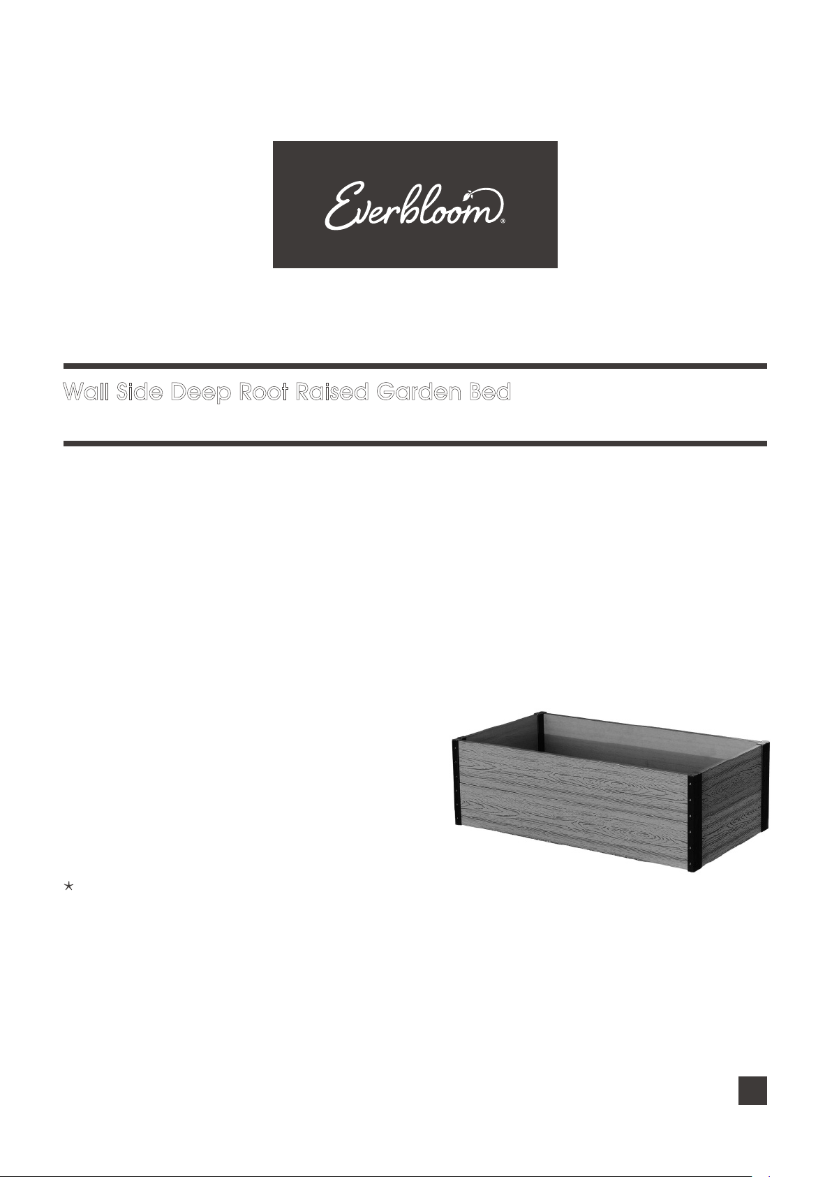
Wall Side Deep Root Raised Garden Bed
Installation Guide
Thank You!
You’re only a few steps away from your perfect vegetable
garden or elevated planter. We hope you enjoy!
Before You Start
Please read the instructions carefully to familiarize
yourself with every detail and step involved. Keep this
manual for future reference. Find a suitable space to
assemble your new Wall Side Raised Garden Bed.
You need at least 45” x 24” (116 x 61cm) for the finished
product. A flat and firm area (like a garage floor or flat
yard space) is perfect! The only tool you may need is a
rubber mallet.
Important Notes
Small parts are included; we advise you to keep
them away from children and pets.
We also suggest having another person help you
assemble. Maximum Load capacity: approximately
7 cu. ft. of soil
Subscribe at www.everbloom-garden.com
for extra savings and upgrading information!
Model# R144524
Dimensions 45" L x 24" W x 14" H
Everbloom-Garden.com
Questions or Comments?
Email us at [email protected]
1
Page 2
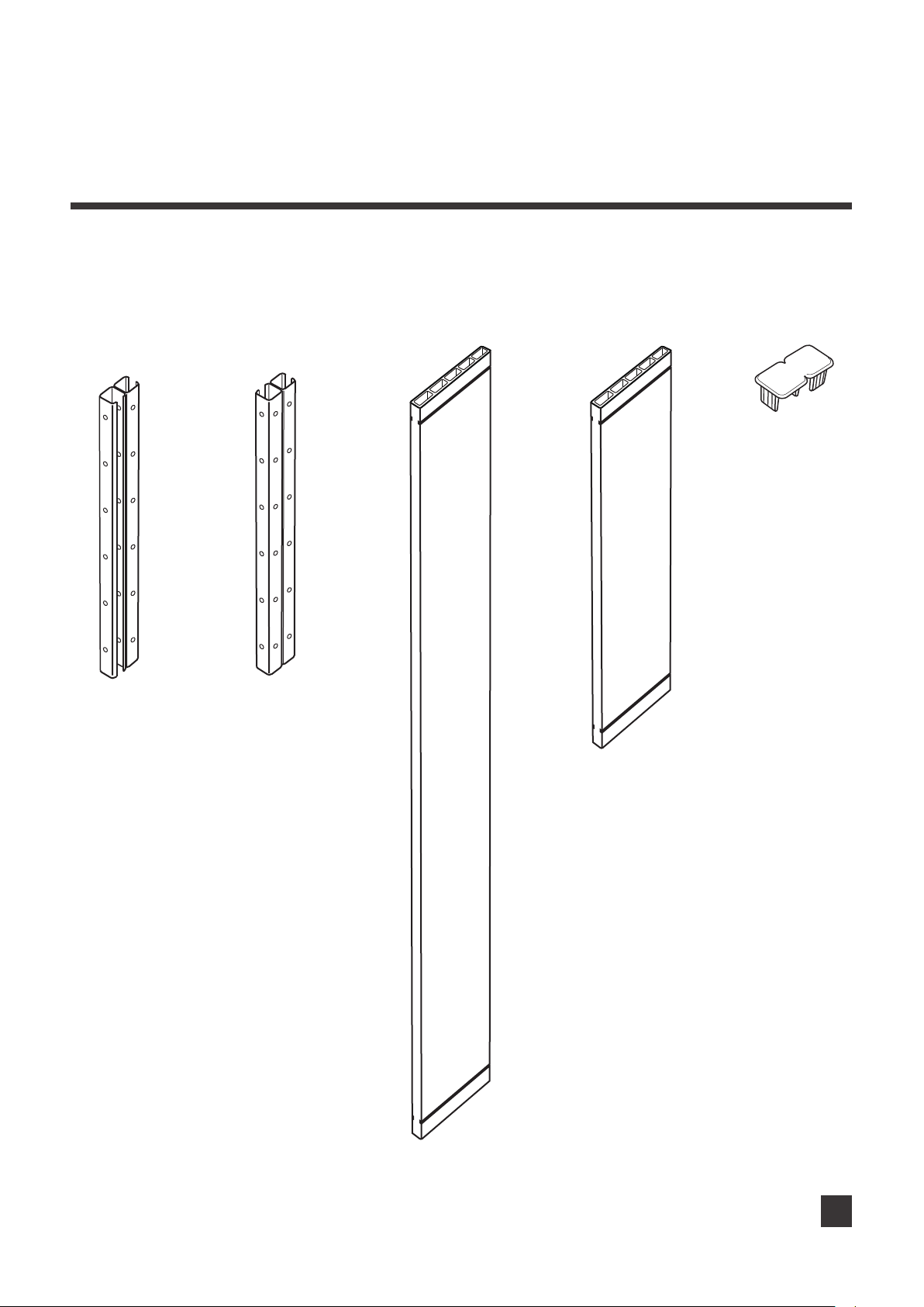
Parts List
Wall Side Deep Root Raised Garden Bed - 45" L x 24" W x 14" H
Left Corner
Post
X 2
Top
Right Corner
Post
X 2
Top
Long Board
X 4
Short Board
X 4
Post Cap
X 4
+ 2pc
replacement
Bottom
Bottom
540mm
1140mm
2
Page 3
Assembly
Wall Side Deep Root Raised Garden Bed - 45" L x 24" W x 14" H
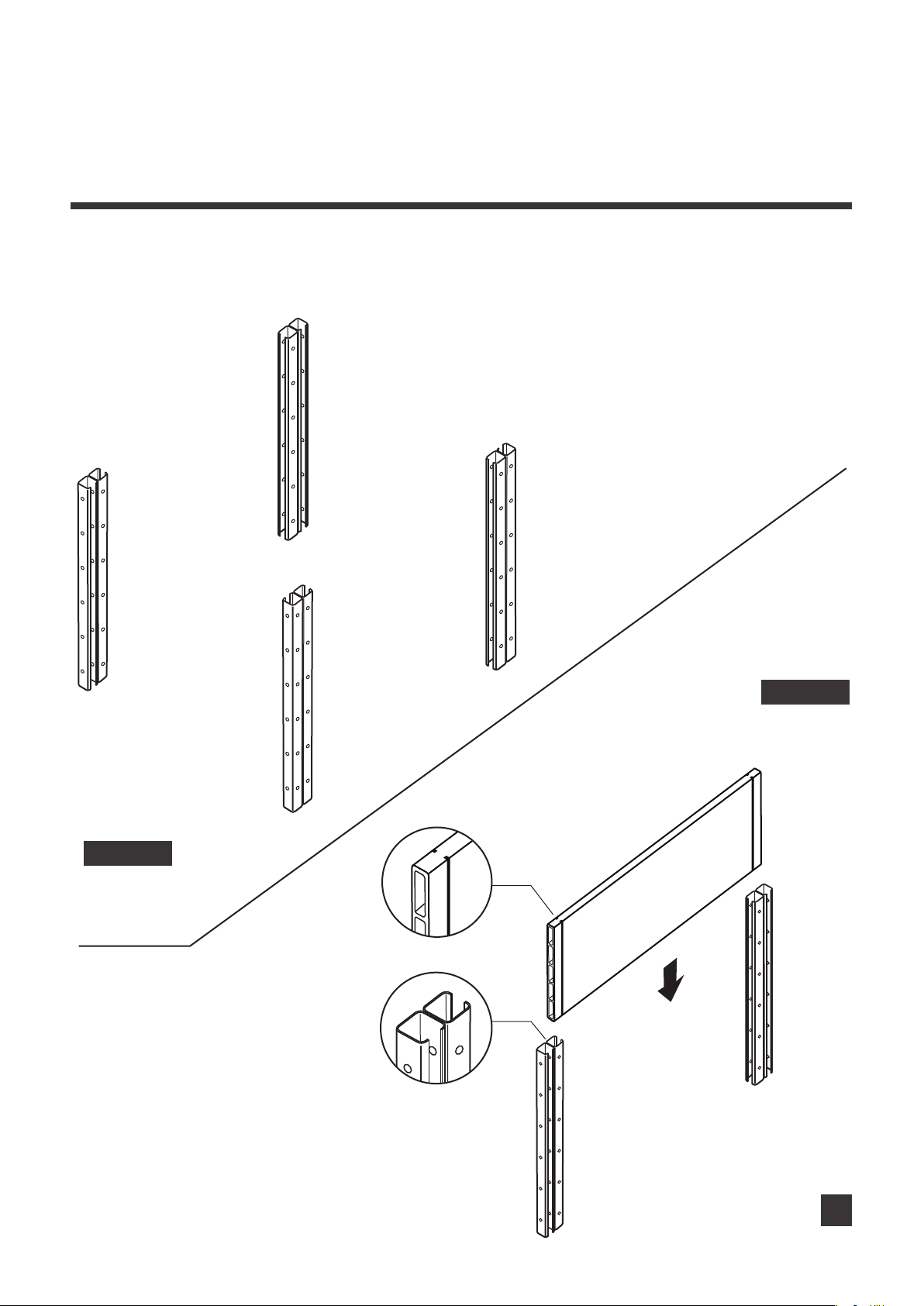
Start by making sure each corner post is oriented correctly. Reference image 1. Slide one short board into
the corner posts from above.
Note: The boards need to be placed in the inward “U” shape of the brackets. (Image 2).
Right Corner
Post
Left Corner
Post
Left Corner
Post
IMAGE 1
Right Corner
Post
IMAGE 2
Short
Board
Right
Corner
Post
Left Corner
Post
3
Page 4
Assembly
Wall Side Deep Root Raised Garden Bed - 45" L x 24" W x 14" H
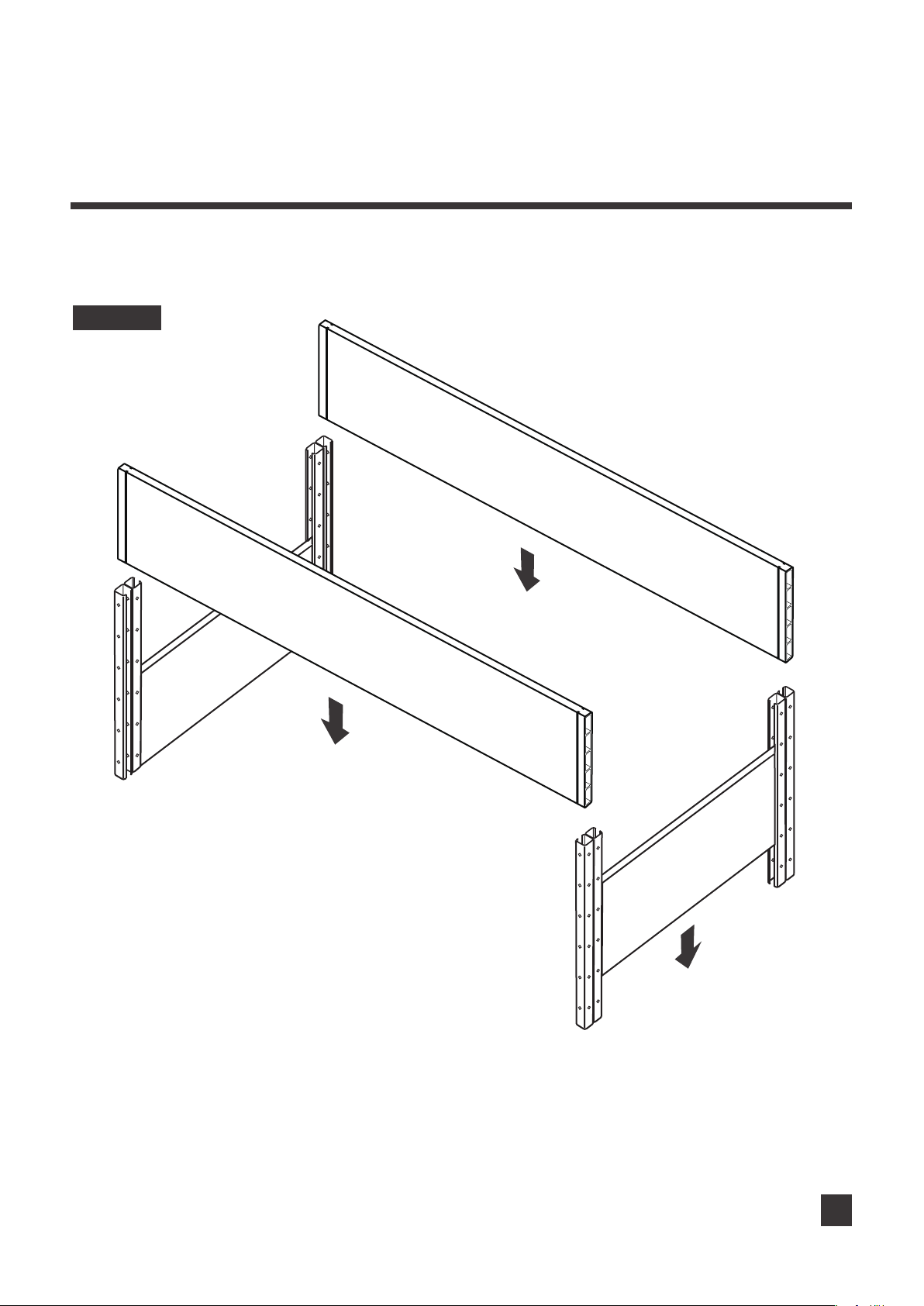
Slide the other short board and two long boards into the corner posts from above, as shown in Image 3.
IMAGE 3
Long
Right Corner
Post
Long
Board
Board
Left
Corner
Post
Left
Corner
Post
Right Corner
Post
4
Page 5
Assembly
Wall Side Deep Root Raised Garden Bed - 45" L x 24" W x 14" H
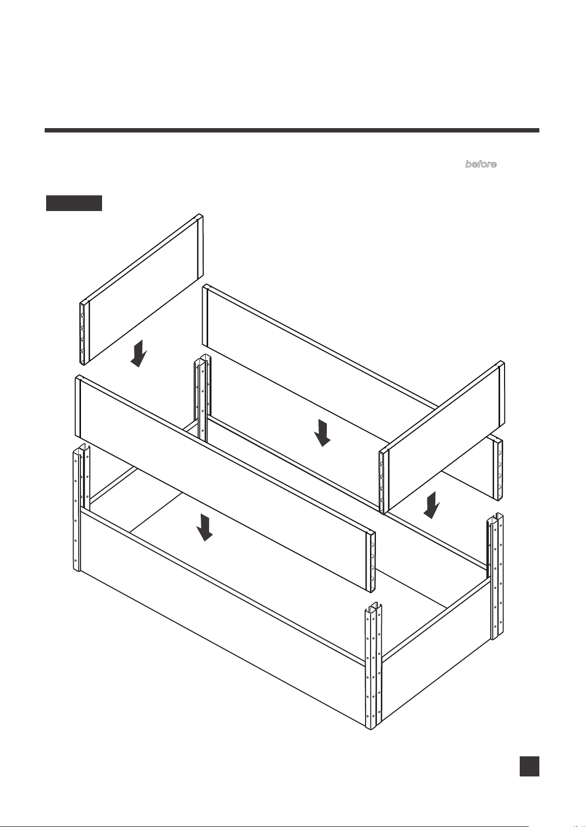
Slide the rest four boards to form the second layer, as shown in Image 4.
Note:If you want to add trellis kit onto this bed, please assemble the extension connectors before this step,
to avoid disassembling the boards later.
IMAGE 4
Short
Board
Long
Right
Corner
Post
Board
Short
Board
Left
Corner
Post
Long
Board
Left
Corner
Post
Right Corner
Post
5
Page 6
Assembly
Wall Side Deep Root Raised Garden Bed - 45" L x 24" W x 14" H
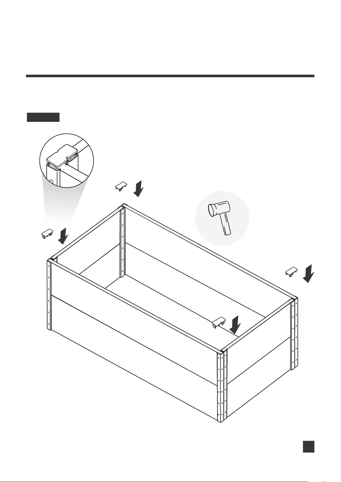
If necessary, use your rubber mallet to ensure the boards are tightly in place. Cover the brackets with the
4 end caps, as shown in Image 5.
IMAGE 5
Post Cap
X 1
Post Cap
X 1
Rubber
Mallet
Note: Store the additional
caps for future use.
Post Cap
X 1
Post Cap
X 1
6
Page 7
Notes
Wall Side Deep Root Raised Garden Bed - 45" L x 24" W x 14" H
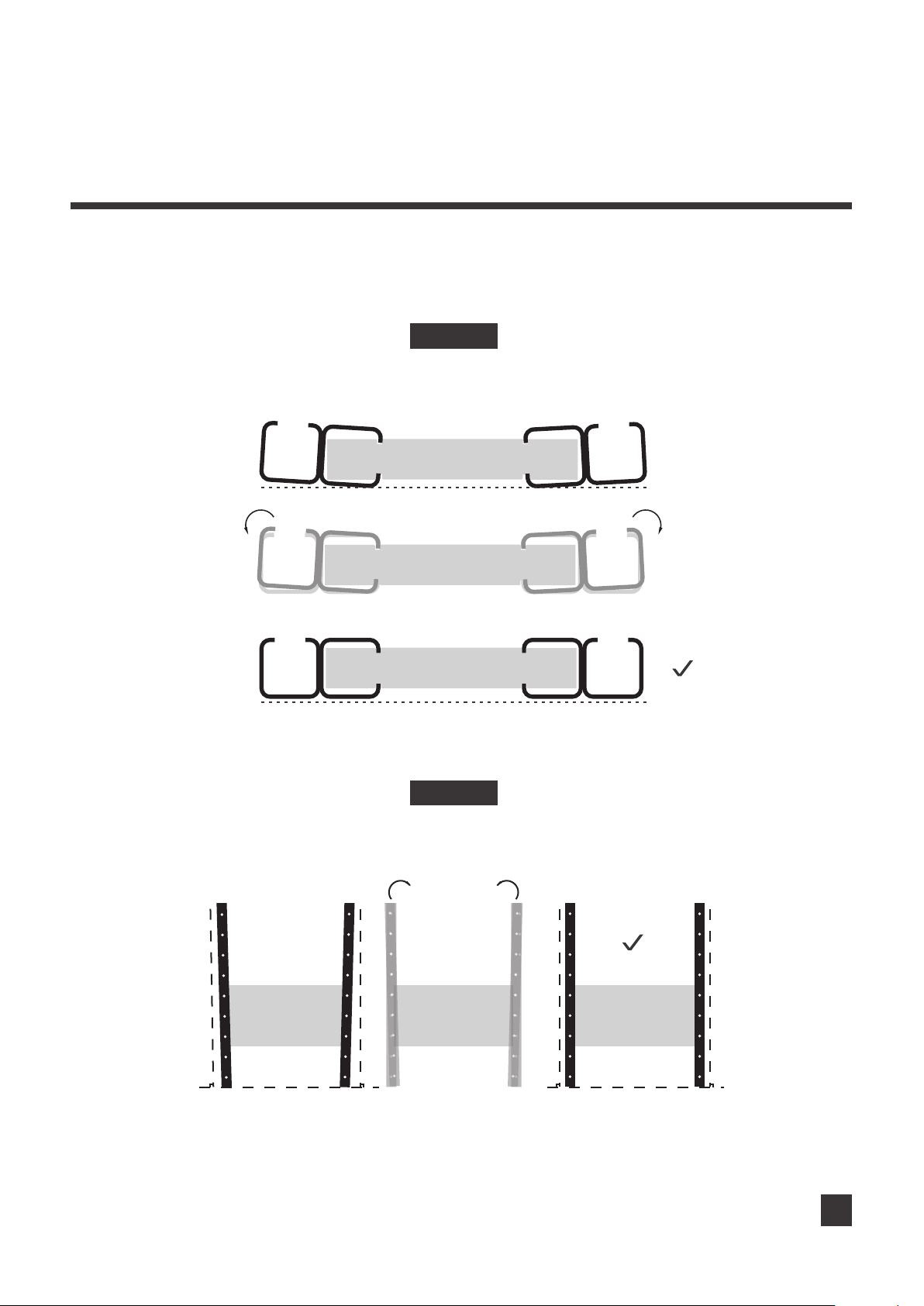
Sometimes there might be a misalignment of the Corner Posts as shown in Image 6 and Image 7, which
may result in difficulty of sliding boards into the brackets. Please adjust them to the right position so that
they are parallel to each other, and perpendicular to the ground.
IMAGE 6
Assembling Problem 1
X
X
IMAGE 7
Assembling Problem 2
7
Page 8

Bloom On.
Everbloom-Garden.com
US Patent Pending
Subscribe at www.everbloom-garden.com for
extra savings and upgrading information!
Distributed by:
Dynaforge Trading LLC
St. Paul, MN55101
Email: [email protected]
Page 9
Thank You!
You’re only a few steps away from your perfect vegetable
garden or elevated planter. We hope you enjoy!
Trellis Assembly Kit
Installation Guide
Before You Start
Please Read the instructions carefully to familiarize yourself with every
detail and step involved. Keep this manual for future reference. Find a
suitable space to assemble the Trellis Kit.
Important Notes
Small parts are included; we advise you to keep them away from children
and pets. We also suggest having another person help you assemble.
Model# T334517K2 / T333619K2
Subscribe at www.everbloom-garden.com for extra
savings and upgrading information!
Page 10
Model# T334517K2 / T333619K2
Trellis Assembly Kit
Installation Guide
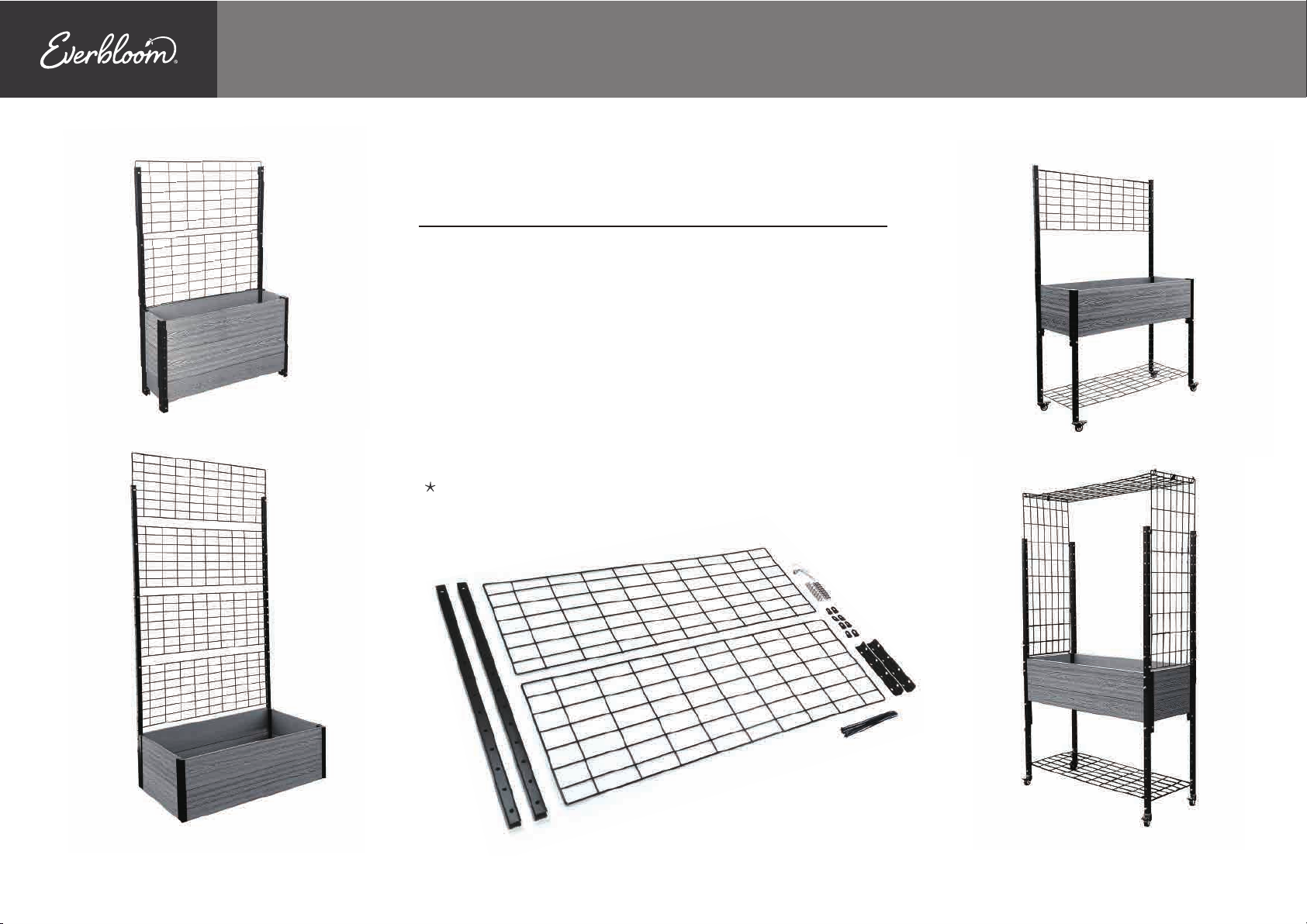
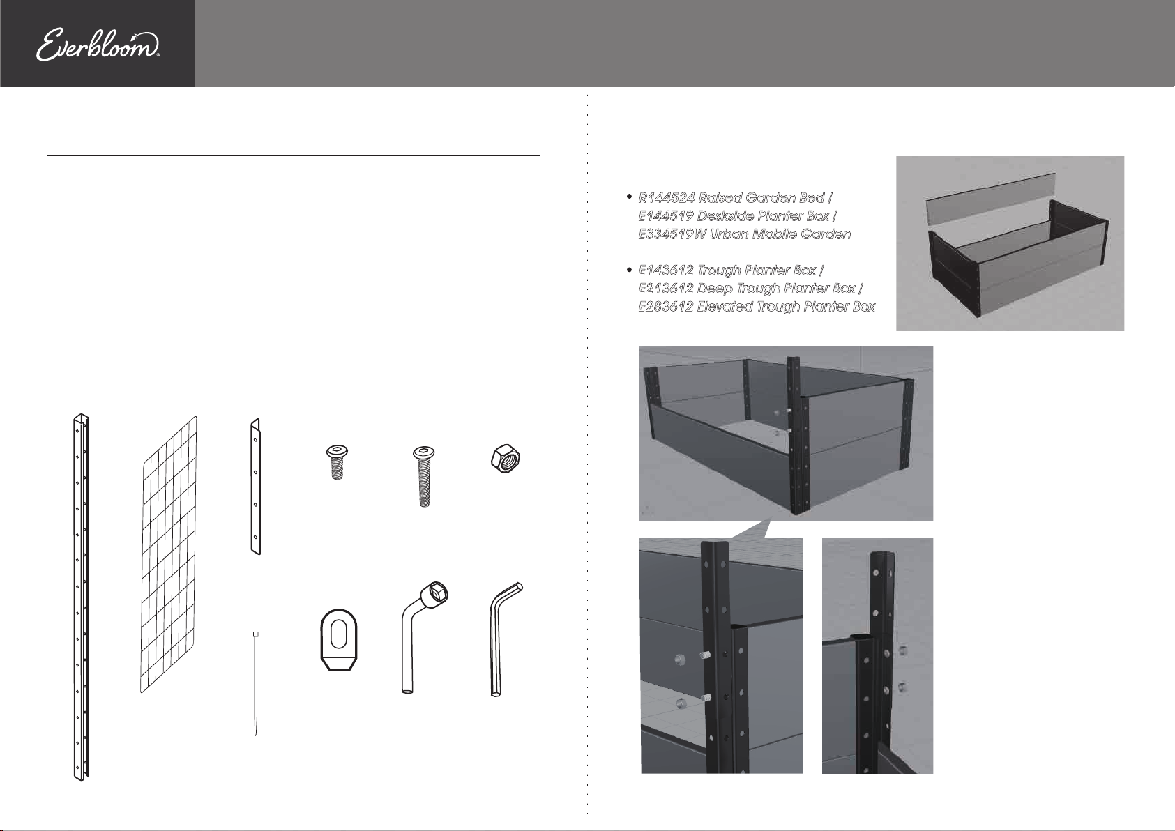
Everbloom Trellis Assembly Kit can be firmly attached from Raised or
Elevated Garden Bed to expand your growing space vertically for your
climbing vines and veggies.
It takes at lease two people to assemble this trellis.
Parts Includes:
33” Extension
Pole
X 2
Steel Wire
Panel
X 2
Corner
Connector
X 2
Cable Tie
X 12
Stainless
Steel
Bolt
X 16
Connector
Washer
X 4
Stainless
Steel
Long Bolt
X 4
Nut Driver
X 1
Stainless
Steel Nylon
Nut
X 20
Hex Key
X 1
Installation 1
Create an additional solid growing
space of 33” height on EverBloom
R144524 Raised Garden Bed /
E144519 Deskside Planter Box /
E334519W Urban Mobile Garden
with T334517K2
E143612 Trough Planter Box /
E213612 Deep Trough Planter Box /
E283612 Elevated Trough Planter Box
with T333619K2
view from back
Before installation, please
be sure that the top back
long board hasn’t been
installed, or has been
taken off.
1. Align the corner
connector to outer corner
post, as shown in Pic.1.
1
The lower two screw holes
of the connector and the
top two screw holes of
corner post should align.
Insert bolt from inside of
corner post to the corner
connector as shown in
Pic.1a and Pic. 1b.
the nylon lock nut by hand,
as shown in Pic.1c.
Turn on
Model#: T334517K2
1140 x 420mm
Model#: T333619K2
900 x 420mm
view from back
1a 1b
view from front
Note:
Pay attention to the position
and direction of the bolts
and nuts.
1b
Page 11
view from back
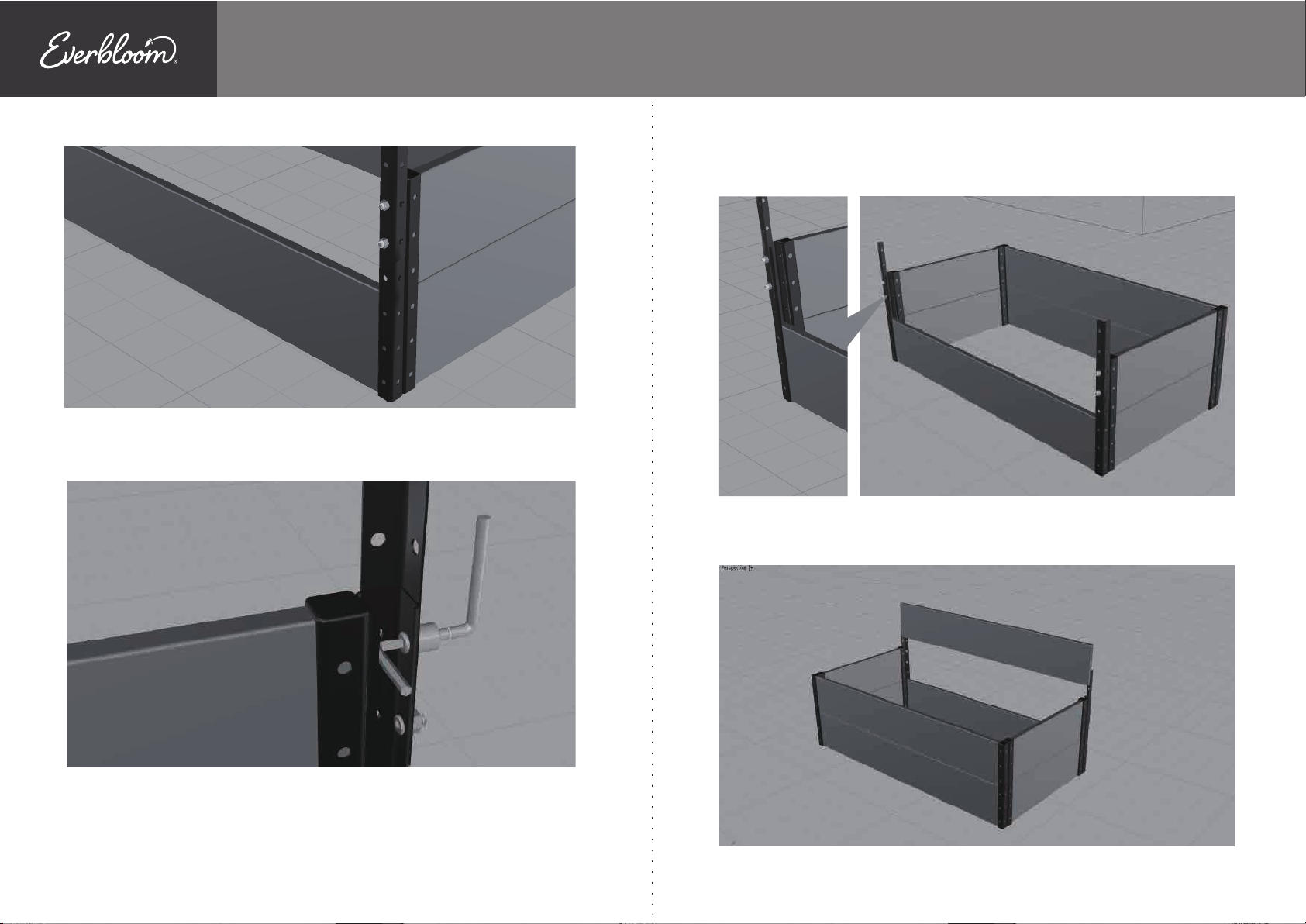
2. Tighten bolts and nuts with hex key and nut driver, as shown in Pic.2.
Model# T334517K2 / T333619K2
3. Install another corner connector follow steps above, as shown in Pic.3
and Pic.3a.
1c
33a
view from front
Note:
Please lift the corner connector when you tighten the bolts and nuts. Be sure
the screw hole centers of connector and post align. If the corner connector is
installed lower, it may cause difficulty in fixing the extension poles.
4. Insert the top back long board, as shown in Pic.4.
view from front
4
Page 12
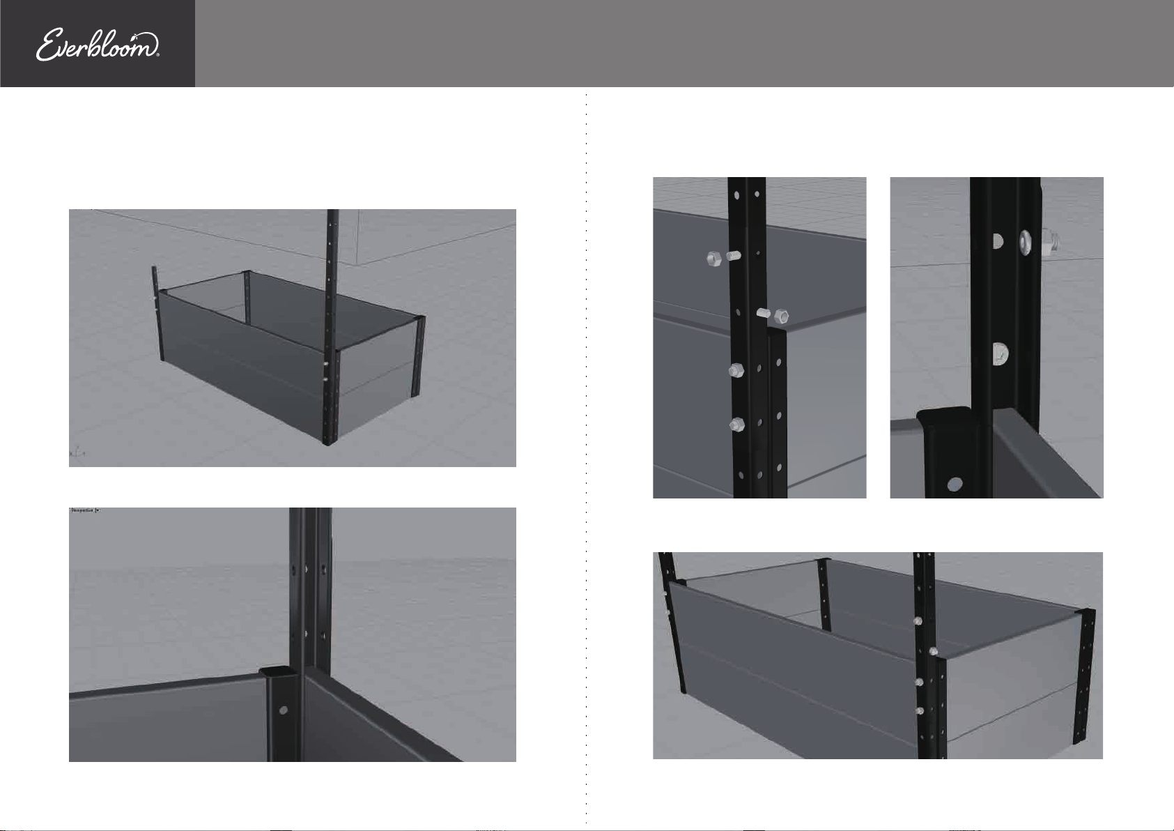
5. Attach the extention pole to the corner connector, as shown in Pic.5. Be
sure the slot of the pole is facing to the other corner connector, as shown
in Pic.5a.
Model# T334517K2 / T333619K2
6.
Insert bolt from inside of the extention pole to the corner connector, as shown
in Pic.6 and Pic. 6a.
Turn on the nylon lock nut by hand, as shown in Pic.6b.
view from back
view from front
5a
5
view from back view from front
Note:
Pay attention to the position and direction of the bolts and nuts.
view from back
6 6a
6b
Page 13
Model# T334517K2 / T333619K2
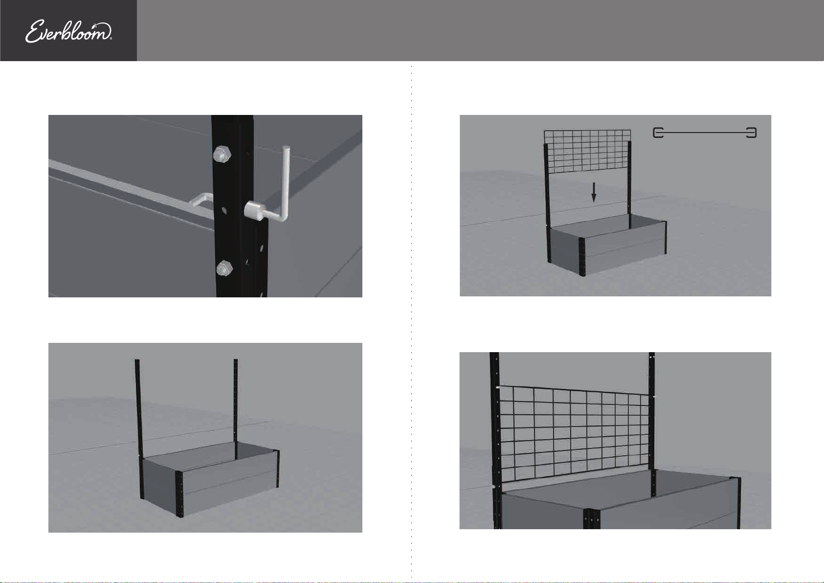
7. Tighten the bolts and nuts with hex key and nut driver, as shown in Pic.7.
view from back
7
8. Install another extention pole following step 4-6 above, as shown in Pic.8.
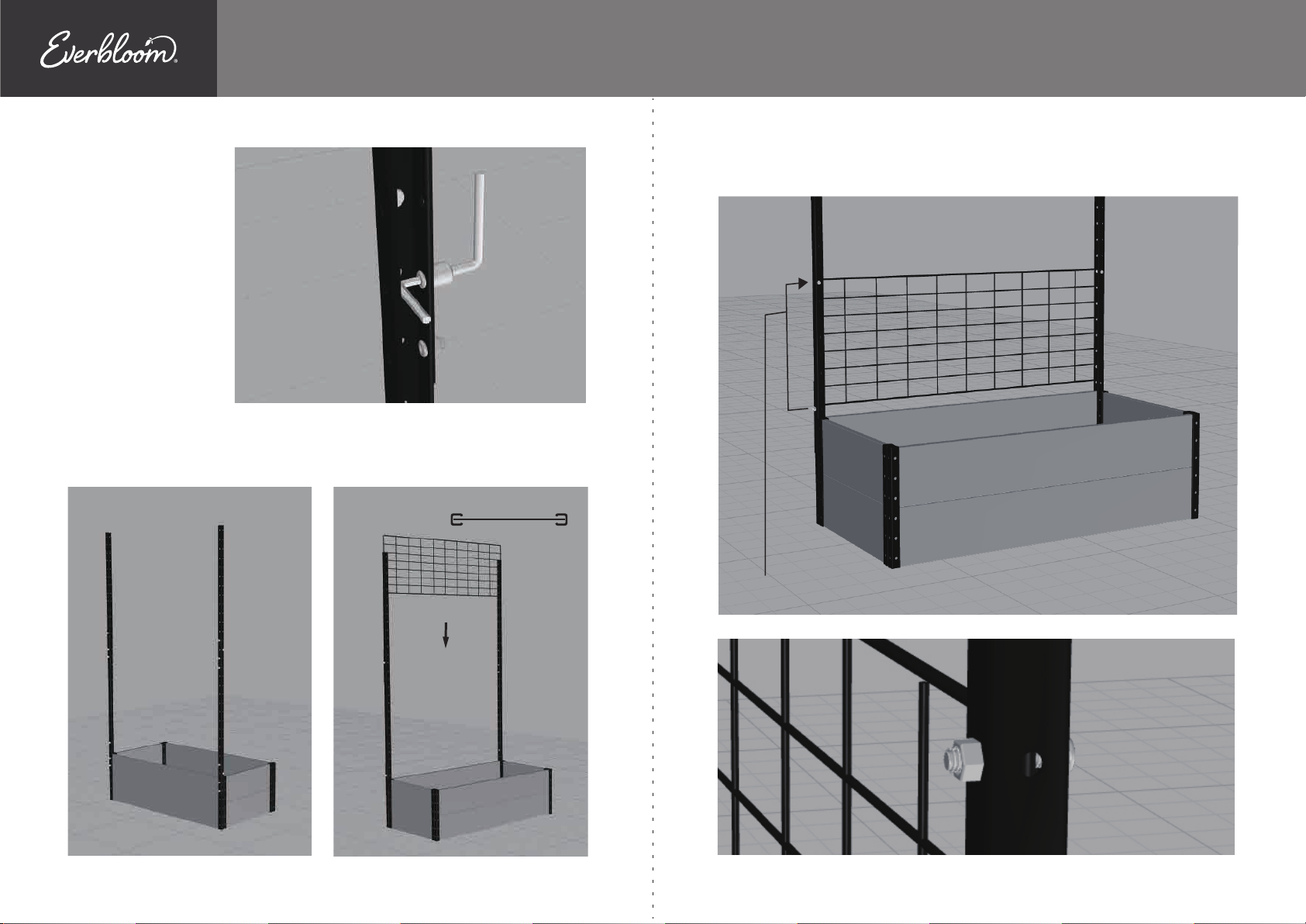
9. Slide the steel wire panel from above, as shown in Pic.9.
top view
9
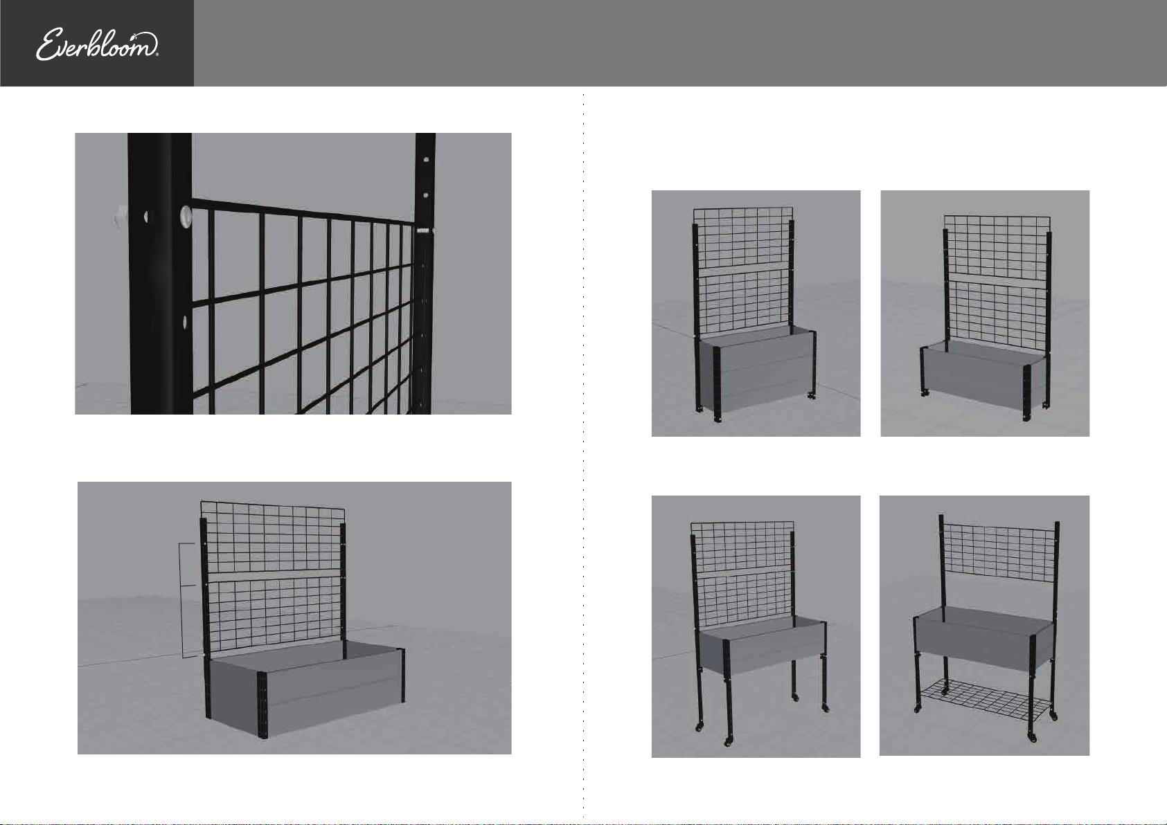
10. Fix the steel wire panel with long bolt and nut, as shown in Pic.10 and
Pic.10a.
view from front
8
10
Page 14
10a
Model# T334517K2 / T333619K2
Note:
You can choose different heights according to the size of the grid, especialy
installing one steel wire panel on the extension poles.
11. Slide another steel wire panel and fix it with long bolt and nut, as
shown in Pic.11.
the 3rd hole
from top
the 7th hole
from top
11
One Trellis Kit bulit on E213612
Deep Trough Planter Box
One Trellis Kit bulit on E334519W
Urban Mobile Garden -1
One Trellis Kit bulit on E143612
Trough Planter Box
One Trellis Kit bulit on E334519W Urban
Mobile Garden -2
Page 15
Model# T334517K2 / T333619K2
Installation 2
Create a 45”x16.5” bottom tray on EverBloom
E334519W Urban Mobile Garden
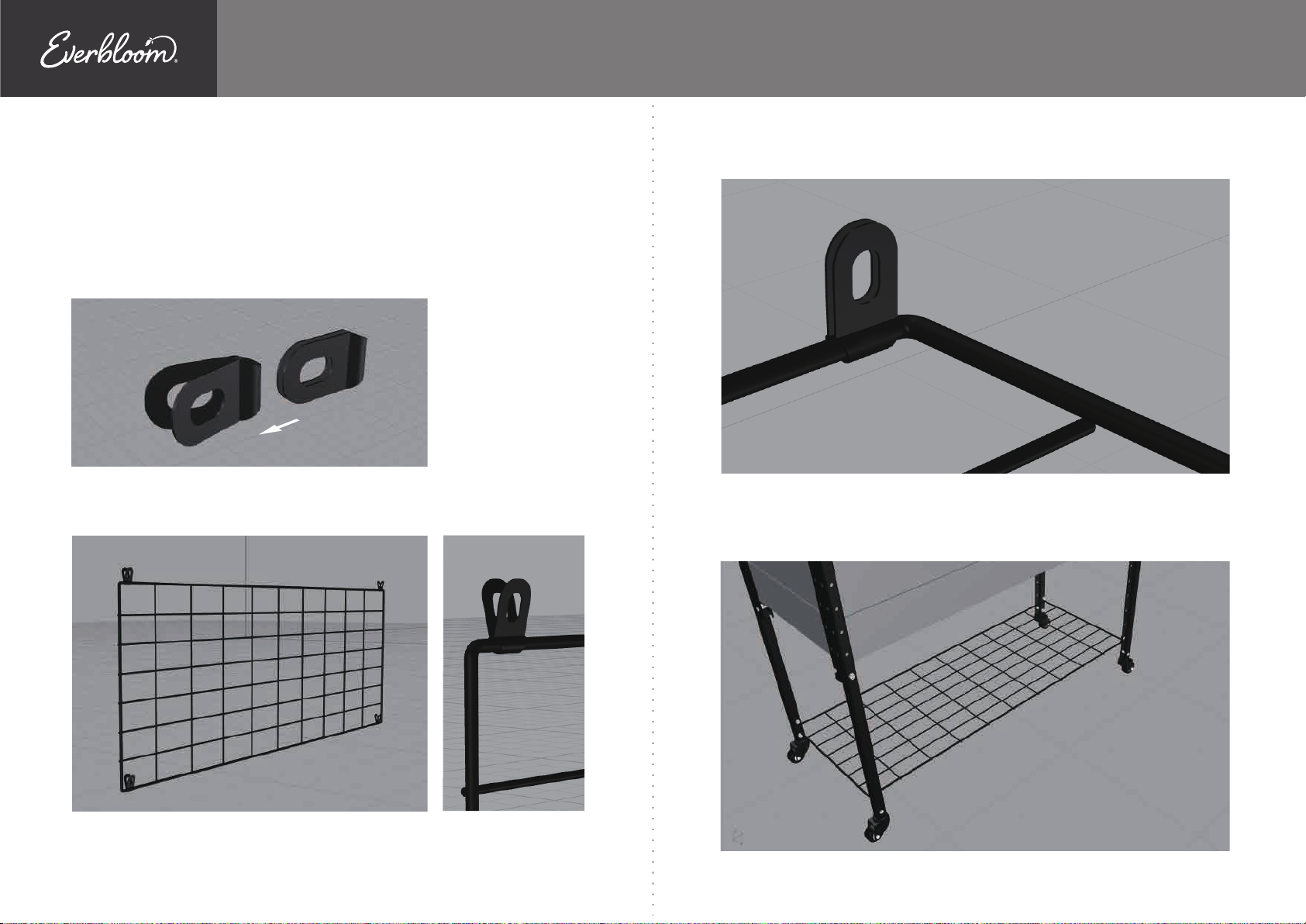
1. Open all the steel connector washers, as shown in Pic.12.
12
2. Clamp the connector washers onto the steel wire panel, as shown in
Pic.13 and Pic.13a.
3. Close all the connector washers, as shown in Pic.14.
14
4. Align the steel wire panel to four post brackets, as shown in Pic.15. Then,
fasten a connector washer on the steel wire panel to post bracket with
bolt and nut, as shown in Pic.15a and Pic.15b.
13
Note:
Pay attention to the position and direction of the connector washer on the panel.
13a
15
Page 16
15a 15b
Model# T334517K2 / T333619K2
Installation 3
Create an additional solid growing space of 74” height on EverBloom
R144524 Raised Garden Bed with T334517K2
R143638 Deep Root Raised Garden Bed /
E213612 Deep Trough Planter Box with T333619K2
This installation need 2 Trellis Assembly Kits.
Before installation, please be sure that the
top back long board hasn’t been installed,
or has been taken off.
Then, follow step 1 to 8 of installation 1.
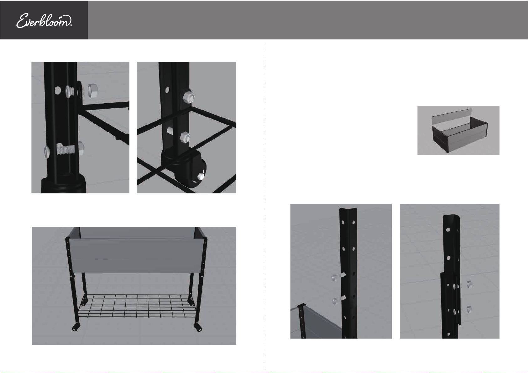
9. Align the corner connector to extention pole, as shown in Pic.1. The lower
two screw holes of the connector and the top two screw holes of corner post
should align.
shown in Pic.17 and Pic.17a.
Pic.17b.
Insert bolt from inside of corner post to the corner connector as
Turn on the nylon lock nut by hand, as shown in
5. fasten the other three connector washers on the steel wire panel to post
brackets with bolts and nuts, as shown in Pic.16.
10
16
17 17a
view from back view from front
Page 17
17b
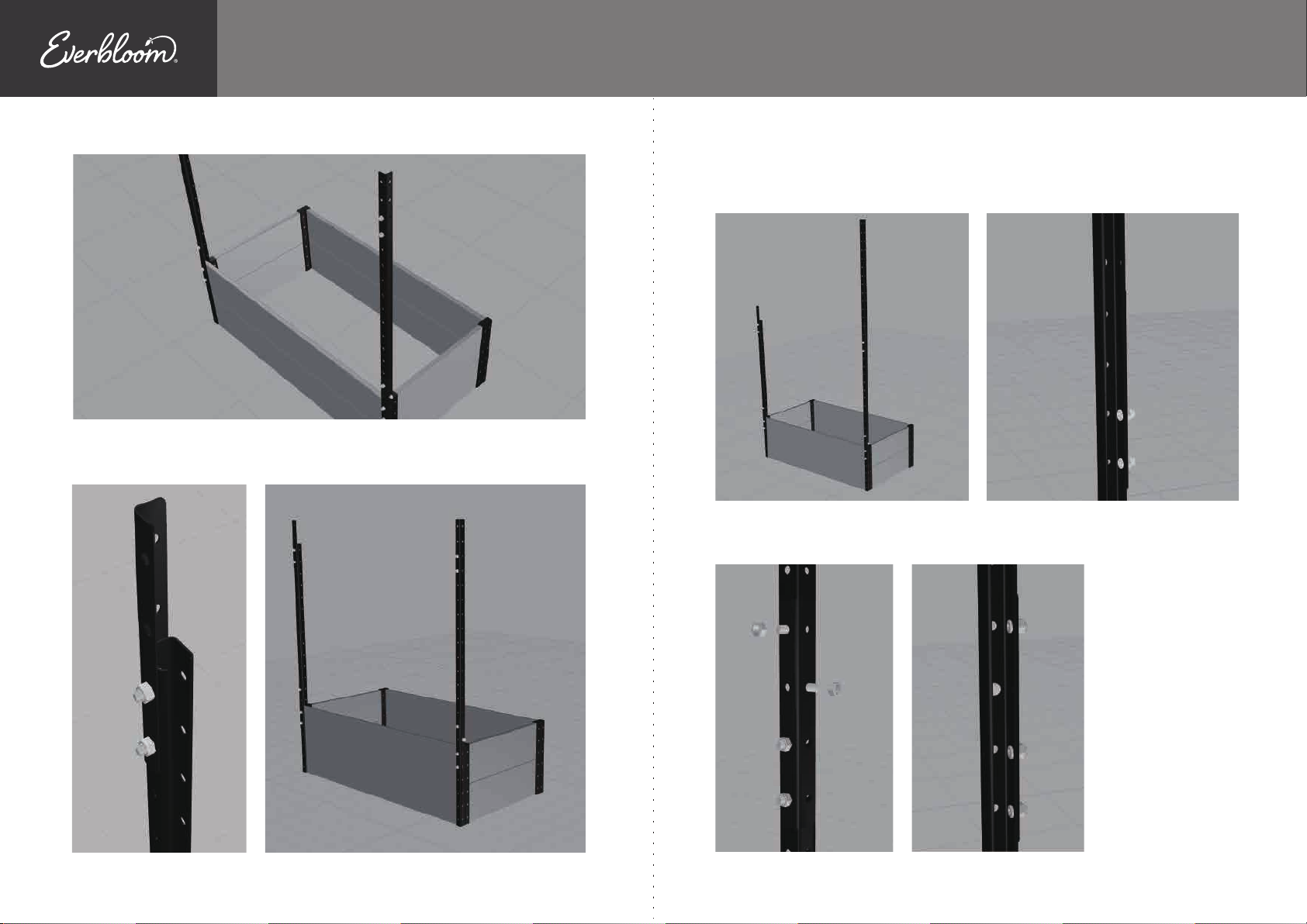
10. Install another corner connector follow steps above, as shown in Pic.18
and Pic.18a.
Model# T334517K2 / T333619K2
11. Attach the extention pole to the corner connector, as shown in Pic.19. Be
sure the slot of the pole is facing to the other corner connector, as shown in
Pic.19a.
19a19
18 18a
Insert bolt from inside of the extention pole to the corner connector, as shown
12.
in Pic.20.
Turn on the nylon lock nut by hand, as shown in Pic.20a.
Note:
Pay attention to the
view from back view from front
20 20a
position and direction
of the bolts and nuts.
Page 18
Model# T334517K2 / T333619K2
13. Tighten all four
bolts and nuts with
hex key and nut driver,
as shown in Pic.21.
21
14. Install another extension pole following step 11-13 above, as shown in Pic.22.
15. Slide the steel wire panel from above, as shown in Pic.23.
top view
16. Fix the steel wire panel with long bolt and nut, as shown in Pic.24 and
Pic.10a.
24the 8th hole from bottom
22
23
view from back
24a
Page 19
Model# T334517K2 / T333619K2
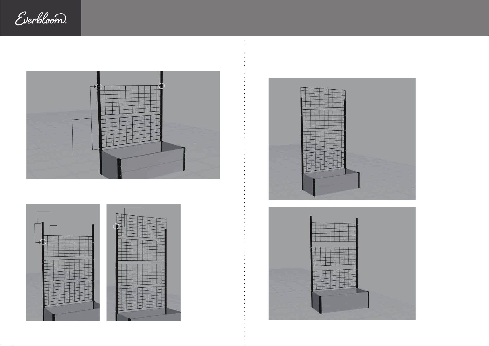
17. Slide the second steel wire panel from above and fix it with long bolts and
nuts , as shown in Pic.25. Please pay attention to the bolts position.
the 16th hole
from bottom
25
18. Slide the left two steel wire panels from above and fix them with long bolts
and nuts , as shown in Pic.26 and Pic.27.
the 7th hole
from above
the 3rd wire
from above
the 5th wire
from above
19. Fasten all the bolts and nuts, Then you can get a solid growing space of
74” height, as shown in Pic.28. Also you can adjust the positions of these steel
wire panels slightly as you like. Style in Pic.29 just is a sample.
28
26 27
Note: Please
pay attention
to the positions
of the bolts.
29
* Three Panels
make wider
interstices
Page 20
Installation 4
Create a pergola of 45” height on EverBloom
E334519W Urban Mobile Garden with T334517K2
This installation need 2 Trellis
Assembly Kits.
Before installation, please be
sure that the top long boards
haven’t been installed, or
have been taken off.
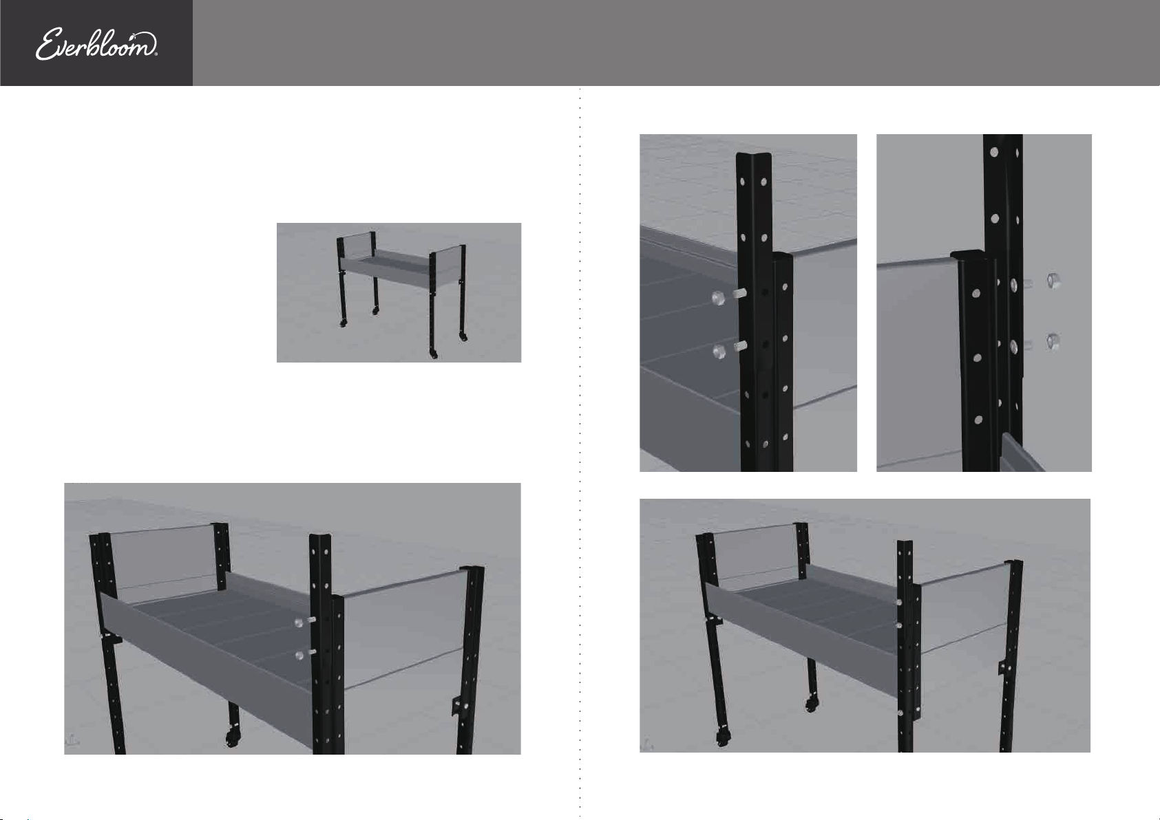
1. Align the corner connector to outer corner post, as shown in Pic.30. The
lower two screw holes of the connector and the top two screw holes of
corner post should align.
connector as shown in Pic.30a and Pic. 30b.
hand, as shown in Pic.1c.
Insert bolt from inside of corner post to the corner
Turn on the nylon lock nut by
Model# T334517K2 / T333619K2
30a 30b
view from back view from front
30
view from back
30c
Page 21
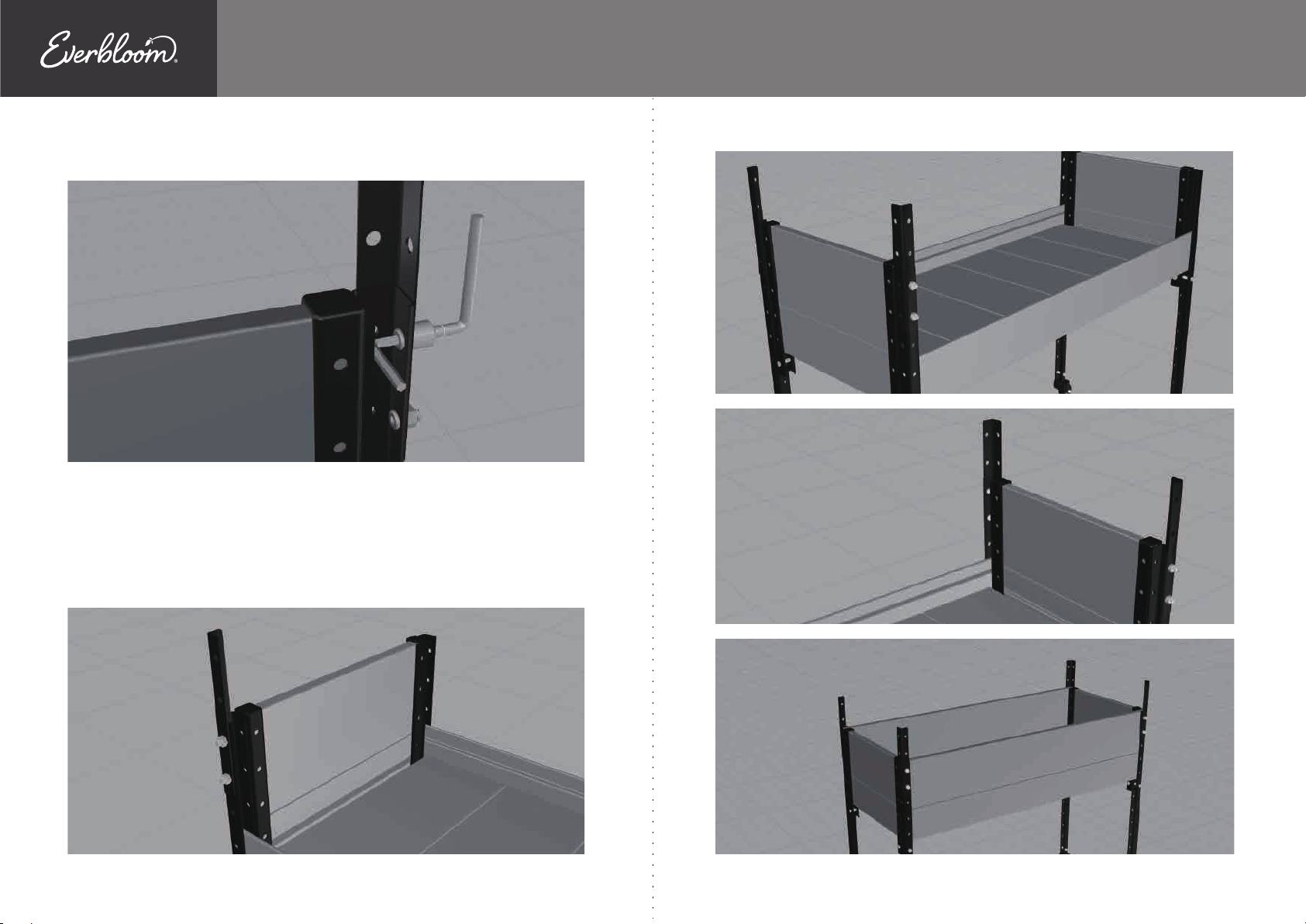
2. Tighten bolts and nuts with hex key and nut driver, as shown in Pic.31.
Model# T334517K2 / T333619K2
33
31
Note:
Please lift the corner connector when you tighten the bolts and nuts. Be sure the
screw hole centers of connector and post align. If the corner connector is
installed lower, it may cause difficulty in fixing the extension poles.
3. Install another three corner connector follow steps above, as shown in
Pic.32 to Pic.35.
32
34
34
35
Page 22
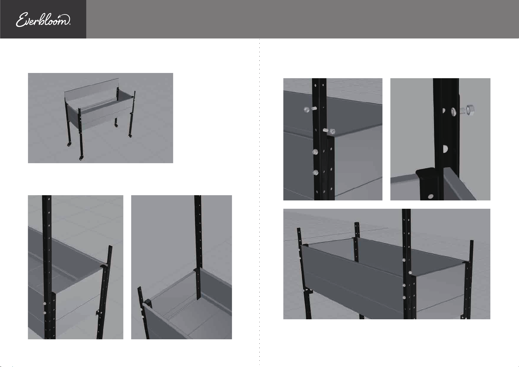
Model# T334517K2 / T333619K2
3. Insert the top long boards, as shown in Pic.36.
36
4. Attach the extention pole to the corner connector, as shown in Pic.37. Be
sure the slot of the pole is facing to the other corner connector on the same
long board, as shown in Pic.37a.
5.
Insert bolt from inside of the extention pole to the corner connector, as shown
in Pic.38 and Pic. 38a.
view from back
Turn on the nylon lock nut by hand, as shown in Pic.38b.
38
view from front
38a
6a
view from front
37 37a
view from back
view from back
Note:
Pay attention to the position and direction of the bolts and nuts.
38b
Page 23
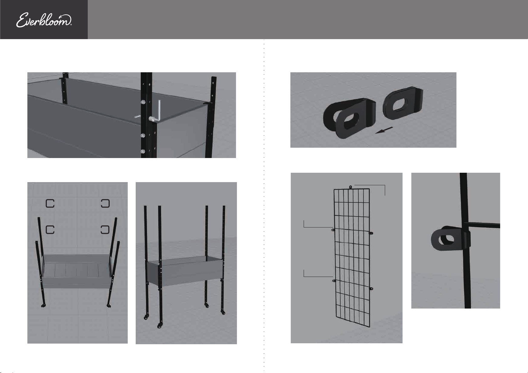
Model# T334517K2 / T333619K2
6. Tighten the bolts and nuts with hex key and nut driver, as shown in Pic.39.
39view from back
7. Install another three extention poles follow step 4-6 above, as shown in
Pic.40 to Pic.41.
8. Open all the steel connector washers, as shown in Pic.42.
42
9. Clamp the connector washers onto the steel wire panel, as shown in Pic.43
and Pic.43a.
the 4th
grid from
top
center
of top
40
4140
the 3rd
grid from
bottom
13
43
13a
43a
Note:
Pay attention to the position and
direction of the connector washer
on the panel.
Page 24
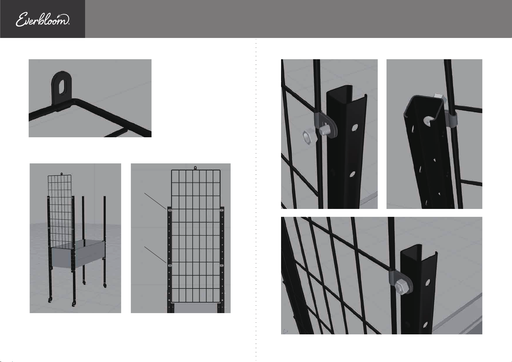
10. Close all the connector
washers, as shown in Pic.44.
44
11. Align the steel wire panel to two extention poles, as shown in Pic.45 and
Pic.45a.
Model# T334517K2 / T333619K2
1st hole
9th hole
45 45a
12. Fasten a connector washer on the steel wire panel to extention poles
with bolt and nut, as shown in Pic.46, Pic.46a and Pic.46b.
view from back view from front
view from back
46a46
46b
Page 25
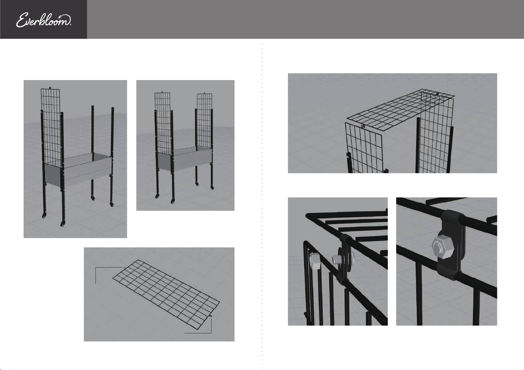
Model# T334517K2 / T333619K2
12. Fasten the other three connector washers on the steel wire panel to extention poles with bolts and nuts, as shown in Pic.47.
48
13. Install another steel wire panel
47
follow step 8 to 12, as shown in
Pic.48.
15. Align the steel wire panel to those two installed panels, as shown in Pic.50.
50
16. Fasten two connector wshers with bolt and nut, as shown in Pic.51 and
Pic.51a.
14. Clamp the
connector washers
onto the third steel
wire panel. Then,
close the both
connector washers,
as shown in Pic.49.
center
of short side
center
of short side
49
13a
51a51
Note:
The direction of these two connector washers should be opposite.
Page 26
Model# T334517K2 / T333619K2
17. Tighten the bolt and nut, as shown in Pic.52.
52
18. Fasten the other two connector washers, as shown in Pic.53 and Pic.53a.
19. Put the roof panel between the two straight panels, as shown in Pic.54.
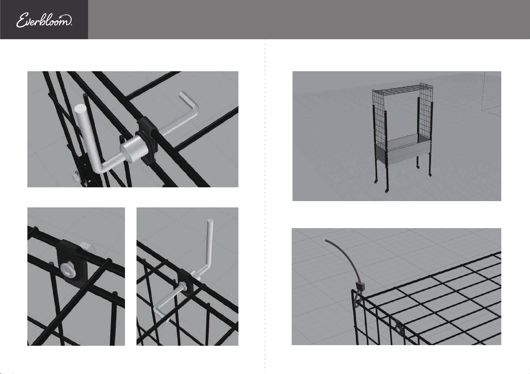
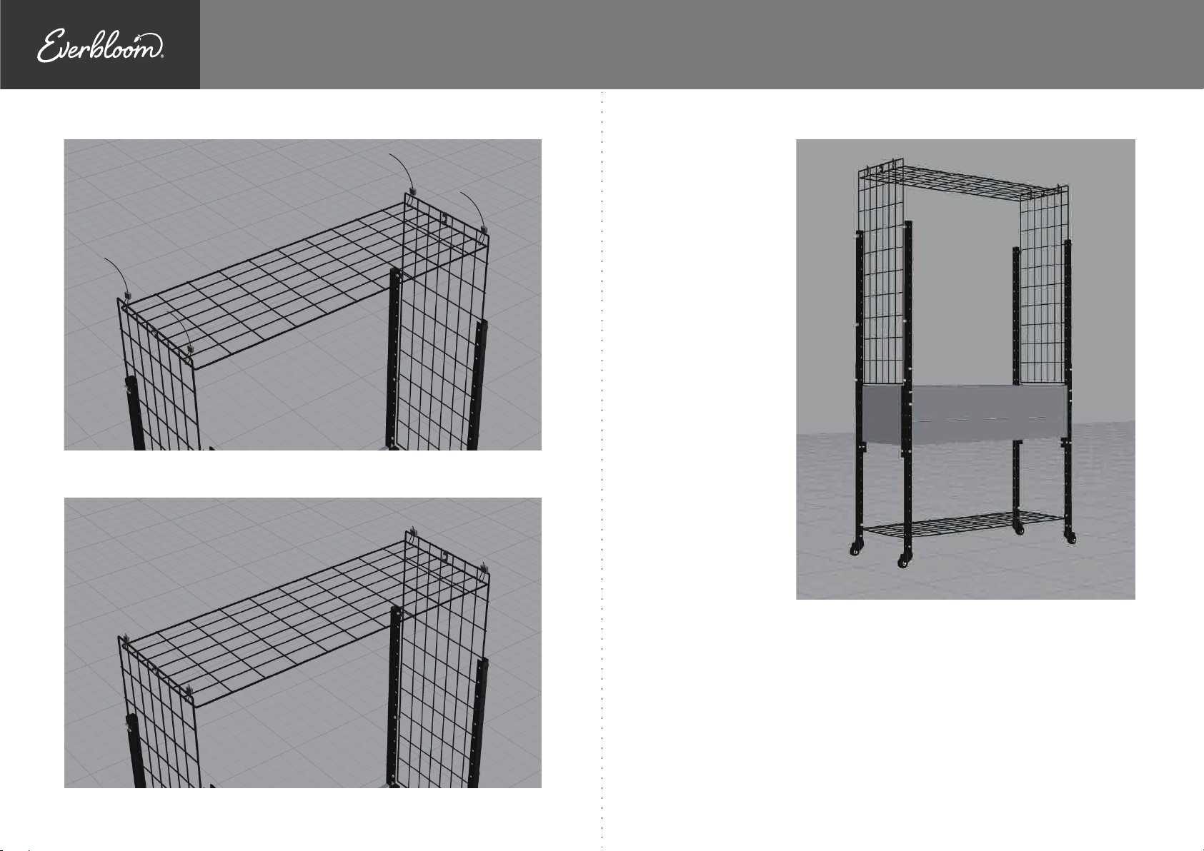
54
20. Fasten the roof panel with side panels with cable ties at four corners, as
shown in Pic.55 and Pic.55a.
53 53a
55
Page 27
55a
Model# T334517K2 / T333619K2
21. Then you can
get a a pergola of
45” height on our
36” Urban Mobile
Garden, as shown
in Pic.57.
21. Tighten all the cables ties and cut extra ties, as shown in Pic.56.
56
57
Note: Use the remaining panel to make a tray on this
elevated garden bed, which can reinforce the stability
of the structure.
55
Page 28

Bloom On.
Everbloom-Garden.com
US Patent Pending
Subscribe at www.everbloom-garden.com for
extra savings and upgrading information!
Distributed by:
Dynaforge Trading LLC
St. Paul, MN55101
Email: [email protected]
 Loading...