

Ever SINLINE RT XL 1250, SINLINE RT XL 850, SINLINE RT XL 650, SINLINE RT XL 1650, SINLINE RT XL 3000 Quick Reference Manual
...Page 1
>10cm
>10cm
+5 ÷ +35 °C
max. 1,8m
b. Rear panel:
5 6
1 2
4 7
3
5 6
1 2
4 7
3
5. DESCRIPTION OF LCD DISPLAY ICONS
v3 20150917Type 01
SINLINE RT XL 650 SINLINE RT XL 1250
SINLINE RT XL 1650
SINLINE RT XL 2250
SINLINE RT XL 3000
SINLINE RT XL 850
1. Output sockets
PN-E-93201 (10 A)
2. Output sockets
IEC 320 C13 (10 A):
white - controlled
black - non-controlled
3. Automatic fuse
4. Mains input:
IEC 320 C14 (10 A)
SINLINE RT XL 650 - 850
IEC 320 C20 (16 A)
SINLINE RT XL 1250 – 3000
5. Fan
6. Ethernet communication port
7. USB communication port
8. Expansion card compartment
9. Telecommunication filter
10. Output socket
IEC 320 C19 (16 A)
SINLINE RT XL 650 | 850
SINLINE RT XL 1250 | 1650 | 2250 | 3000
1
567
8 9
2 3 4
x2
x2
8
8
10
9
9
A
B
C
1
2
3
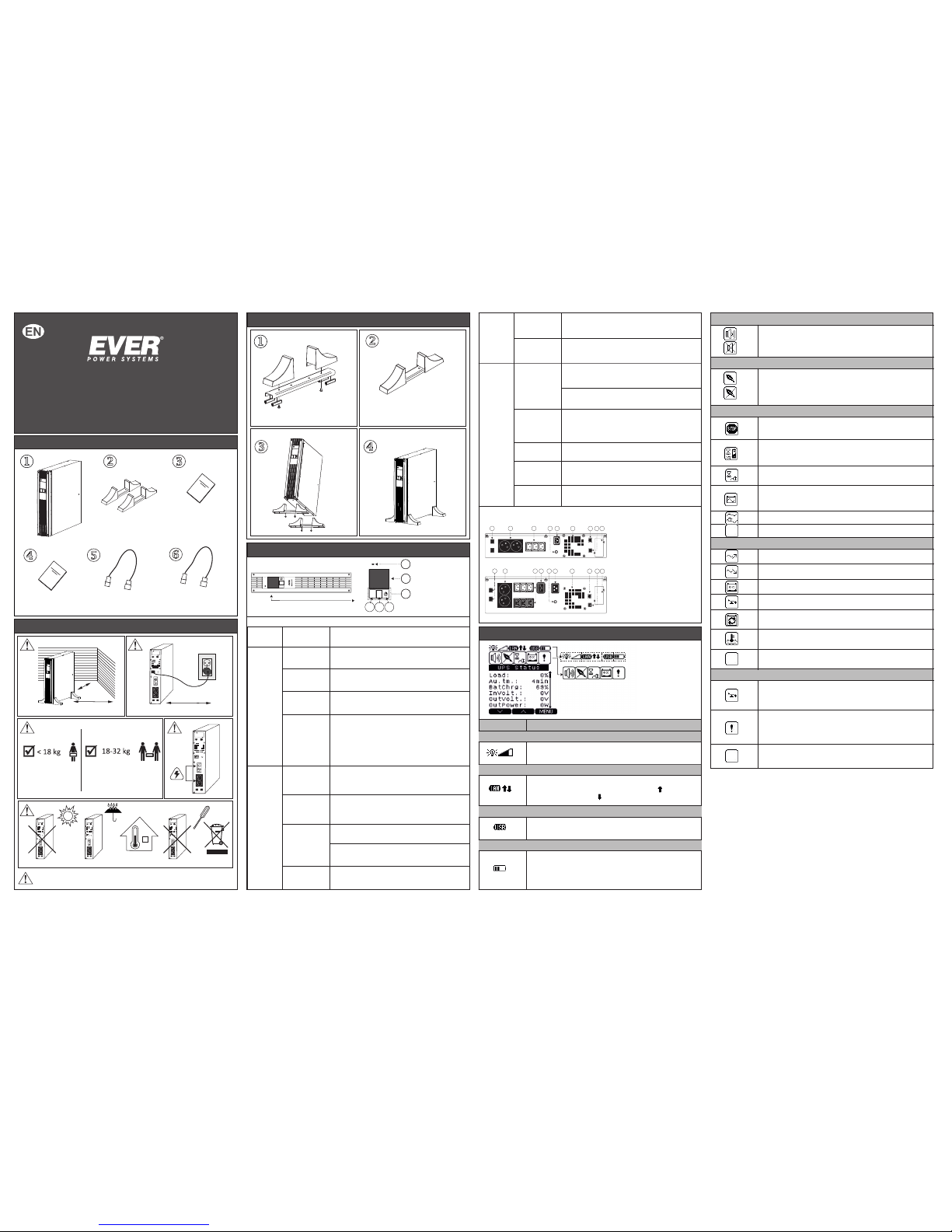
UPS SINLINE RT XL
Note: to obtain detailed information, please read the full instruction manual, which can be
downloaded from our website www.ever.eu.
QUICK REFERENCE GUIDE
1. IN THE PACKAGING
Warranty card
Power cord
CEE 7/7 - IEC 320 C13 (10 A)
lub CEE 7/7 - IEC 320 C19 (16 A)*
USB cable
Quick reference guide
UPS unit
2 sets of Tower supports
for installing the unit vertically
*Depending on the UPS unit
SINLINE RT XL battery back-ups are not designed to power medical
equipment, in particular life support machines!
2. ADDITIONAL REMARKS
3. TOWER VERSION UPS INSTALLATION
4. ELEMENTS OF THE UPS
a. Front panel:
1. Signaling LED
2. LCD display
3. Multi-function buttons:
A, B, C
Functions of the control panel buttons
Button Function
Description
A
B
Switching on
Press and keep the button depressed for over 1 second
to switch the unit on (power supply is switched on).
Switching off
When the UPS is on and the LCD display shows one of the information
screens (screensavers), press and keep the button depressed for over
1 second to switch the unit off (power supply is switched off).
Access
to main menu
When an information screen is displayed, press the button shortly
to enter the main menu.
Confirming /
canceling the
current setting
When the value edit mode is selected, press the button briefly
to change the active object (edited values or command keys).
When in command selection mode, keep the button depressed
to execute the operation assigned to the object.
Switching the unit
on logically
Switching the unit
off logically
Scrolling up
Navigating to the
beginning of the
submenu
When the UPS is not on logically (not operating in back-up or
normal mode), and the LCD display shows one of the information
screens, press and keep the button depressed for over 1 second
to switch the unit on logically (power supply to receiver's
connected to the UPS's output is switched on).
When the UPS is on logically (operating in back-up or normal
mode), and the LCD display shows one of the information
screens, press and keep the button depressed for over 1 second
to switch the unit off logically (power supply to receiver's
connected to the UPS's output is switched off).
Press the button shortly to scroll up between information screens.
Press the button shortly to navigate up the menu options.
Press and keep the button depressed for over 1
second to navigate to the beginning of the submenu.
When in MENU screen, press the button briefly to select or
change the highlighted option (depending on what option is
selected, the button's action is indicated by an icon shown on the
LCD display, next to the button).
Canceling
messages
Increasing the
value of parameters
C
Press the button to cancel the currently displayed message.
Press the button to increase the value of the edited parameter.
Press the button shortly to scroll down between
information screens.
Scrolling down
Switching the
sound alarm on/off
Navigating to the
end of the submenu
Decreasing
the value
of parameters
Confirming
messages
Press and keep the button depressed for over 1 second
to switch the UPS unit's sound alarm on/off.
The function is only accessible from information screens.
Press the button shortly to decrease the value of the
edited parameter.
Press the button shortly to navigate down the menu options.
Press and keep the button depressed for over 1 second
to navigate to the end of the submenu.
Press the button shortly to confirm the currently displayed
message.
Load level signaling. Further segments of the icon light up while the load
increases.
Description
Symbol
1 – UPS output load indicator
2 – LAN connection indicator
The icon is displayed if the UPS is connected with the PC through USB.
3 - USB connection indicator
Battery charge level indicator. Further segments of the icon light up
as the battery charge level increases.
4 - Battery charge level indicator
Signal confirming that the UPS is connected to LAN and visualization of the
direction of transferred data. Packets sent to the network (icon ), packets
received from the network (icon )
Icon indicating the activation / deactivation of sound signal when the UPS
is in back-up (battery) mode. The UPS alarm states is not muted.
5 - MUTE function indicator
Icon activating / deactivating the function of saving energy stored in the batteries.
When the UPS is in back-up (battery) mode and there are no receivers connected
or power consumption is below the threshold value of 30 W, the UPS will
automatically switch off after 15 minutes.
6 – GREEN function indicator
The icon is displayed if one of the following operation modes is activated:
EMERGENCY, STOP or READY.
7 – UPS operation indicator
The UPS is on logically, the mains parameters are correct. After the UPS switches
from the STANDBY mode, the unit waits until the battery is charged to a minimal,
required level declared in % (CONFIGURATION; UPS; STB - ChargeMin).
The UPS operates in STANDBY mode. The mains voltage fails to satisfy
the correctness criteria, the UPS is on logically.
The UPS operates in back-up (battery) mode - there is no mains power supply or
threshold frequency value or effective value of supply voltage are exceeded.
The UPS operates in mains (normal) mode.
The UPS operates in INIT (initialization) mode.
AVR system activity signalization (increasing value).
8 – Messages
AVR system activity signalization (decreasing value).
Low battery charge level.
The icon is displayed in case of an overload of the UPS.
Battery is used up and must be replaced. In order to replace the battery
and to deactivate the icon, please contact EVER Support Centre.
The icon is displayed if the permissible temperature of the battery or inverter
is exceeded.
There are no messages or they are not shown in graphical form
(but are available from the Messages screen).
If the icon is activated, the UPS unit's output is overloaded or shorted, or
there is reversed voltage. The detailed description is available from the Alarms
screen.
9 – Alarms
The icon is displayed in case of: internal error, EPO triggering or if the permissible
temperature of the battery or inverter is exceeded. The detailed description is
available from the Alarms screen. If there is an internal error, please contact the
service department.
No alarms.
Page 2
230V
Ethernet
IEC320
USB
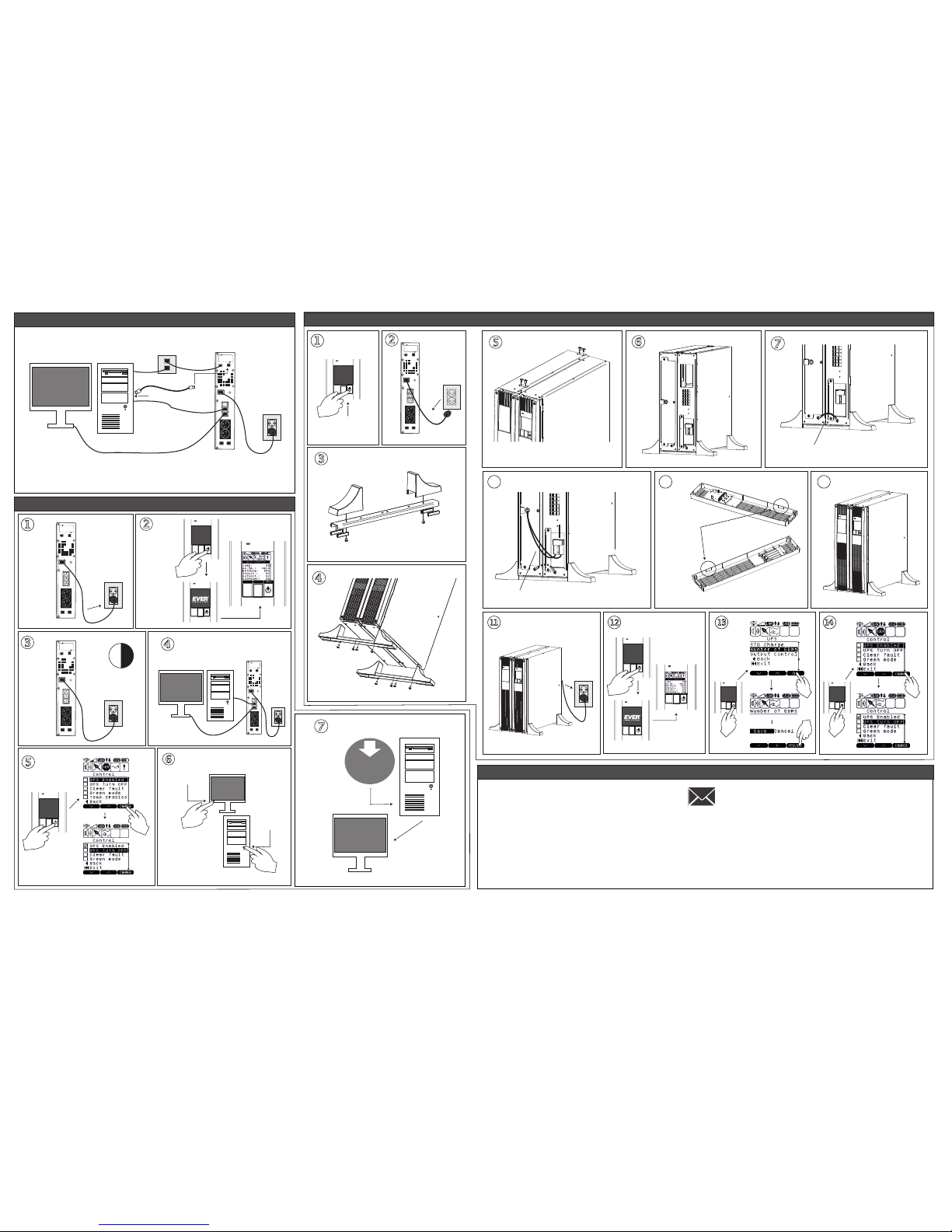
7. FIRST START
230V
230V
4 h
230V
ON
ON
SOFTWARE
DOWNLOAD
WWW.EVER.EU
>1s
Type 01
9. CONTACT
EVER Sp. z o.o.
[email protected]
www.ever.eu
8. INSTALLATION OF THE UPS WITH A BATTERY MODULE
OFF
230V
x2
NOTE: Assemble the feet kit supplied with the battery module.
230V
UPS FRONT PANEL
BATTERY MODULE
FRONT PANEL
Connect the yellow and green earthing conductor
between the battery module and the UPS
Connect the battery module's terminal
to the UPS battery terminal
Remove the cap:
1. Cut
2. Break
>1s
6. BATTERY BACK-UP CONNECTION
v3 20150917
 Loading...