

Page 1
Page 2

Instruction manual for POWERLINE RT 1-3 kVA UPS units
2016-07-13 12:09 Technical Support, tel.: +48 61 6500 400 www.ever.eu
2
TABLE OF CONTENTS
TABLE OF CONTENTS ...................................................................................................................................... 2
INTRODUCTION ................................................................................................................................................. 3
GENERAL FEATURES OF THE UPS UNIT ................................................................................................... 4
SAFETY INSTRUCTIONS AND RECOMMENDATIONS ............................................................................ 6
TECHNICAL DESCRIPTION .......................................................................................................................... 12
UNPACKING THE PRODUCT ...................................................................................................................... 12
What’s in the box? ........................................................................................................................................13
ELEMENTS OF THE UPS - REAR PANEL .................................................................................................. 15
POWERLINE RT 1000 .................................................................................................................................15
POWERLINE RT 2000 .................................................................................................................................16
POWERLINE RT 3000 .................................................................................................................................17
Battery module POWERLINE RT 1000 ........................................................................................................18
Battery module POWERLINE RT 2000/3000 ...............................................................................................19
HOW IT WORKS ............................................................................................................................................ 20
MENU AND FUNCTIONS ............................................................................................................................. 22
INSTALLATION ................................................................................................................................................ 24
MECHANICAL INSTALLATION ................................................................................................................. 25
INSTALLATION OF THE UPS AND BATTERY MODULES VERTICALLY ................................ ........... 25
ELECTRICAL SYSTEM ................................................................................................................................. 26
Input installation...........................................................................................................................................27
Output installation ........................................................................................................................................28
POWER CONNECTIONS ............................................................................................................................... 29
Connecting an external battery module ................................ ................................................................ ........29
Connecting the UPS to the mains .................................................................................................................30
UPS START-UP .............................................................................................................................................. 30
Initial procedure of starting the UPS up ......................................................................................................30
UPS Shut-down procedure ...........................................................................................................................31
DESCRIPTION OF OPERATION OF THE UPS ........................................................................................... 31
MODES OF OPERATION .............................................................................................................................. 31
Stand-by mode ........................................................................................................................................ 31
Bypass mode ................................ ................................................................ ................................ ........... 31
Mains mode............................................................................................................................................. 32
Back-up mode ......................................................................................................................................... 32
Frequency conversion mode ................................................................................................................... 32
ECO Mode .............................................................................................................................................. 33
Error mode .............................................................................................................................................. 33
ADDITIONAL FUNCTIONS .......................................................................................................................... 34
REMOTE EMERGENCY POWER OFF (EPO) / REMOTE ON/OFF (ROO) ............................................... 35
COMMUNICATION WITH EXTERNAL MANAGEMENT/CONTROL SYSTEMS ............................... 36
RS232 PORT AND STATUS SIGNALING.................................................................................................... 36
USB port ........................................................................................................................................................... 37
SNMP/HTTP NETWORK MANAGEMENT CARD ..................................................................................... 37
POWERSOFT .................................................................................................................................................. 37
OPERATING REMARKS ................................................................................................................................. 39
CLEANING ..................................................................................................................................................... 39
STORAGE OF THE UPS ................................................................................................................................ 39
TESTING BATTERIES ................................................................................................................................... 39
BATTERY REPLACEMENT ......................................................................................................................... 40
Replacing UPS internal batteries .................................................................................................................40
Battery disposal ............................................................................................................................................43
TECHNICAL PARAMETERS .......................................................................................................................... 44
TROUBLE SHOOTING .................................................................................................................................... 47
LEGAL REGULATIONS AND WARRANTY ................................................................................................ 48
DECLARATION OF CONFORMITY ............................................................................................................ 48
WARRANTY ................................................................................................................................................... 48
Page 3

Instruction manual for POWERLINE RT 1-3 kVA UPS units
3 www.ever.eu Pomoc Techniczna, tel.: +48 61 6500 400 2016-07-13 12:09
INTRODUCTION
Thank you for purchasing the EVER POWERLINE RT UPS. Please familiarise
yourself with this instruction manual before you begin using the device. This manual
contains all relevant information to ensure correct and safe operation of the unit.
Please read this manual carefully and thoroughly prior to using the EVER
POWERLINE RT. This will help to operate the unit and correctly and safely. This
EVER POWERLINE RT UPS system has been designed and engineered to provide
the highest standard of protection against power failure. We hope that the purchased
UPS will meet your expectations.
A series of hi-tech, on-line (VFI) UPS units (uninterruptable power system), designed
with double conversion topology, for excellent protection of the connected receivers.
The UPS protects sensitive equipment and systems from common problems such as
power outages, drops and interruptions in the mains, surges and other faulty
conditions in the power supply line.
EVER POWERLINE RT series UPS units are mainly used with network devices,
servers, workstations and other electric, electronic and IT devices.
Page 4

Instruction manual for POWERLINE RT 1-3 kVA UPS units
2016-07-13 12:09 Technical Support, tel.: +48 61 6500 400 www.ever.eu
4
GENERAL FEATURES OF THE UPS UNIT
Alongside their excellent performance and reliability, the POWERLINE RT range of
UPS units offers a number of other advantages which include:
On-line real double conversion and sine wave output voltage.
Possibility of selection of high performance operation (ECO).
Scalability (extension) of autonomous operation time thanks to the ability of
connecting more battery modules to the UPS (up to 4 units - optional).
Remote Emergency Power Off (Remote EPO) functionality which interrupts
power supply from the UPS output to loads in extreme situations or in
emergency (e.g. fire).
Remote On/Off (ROO) function for remotely starting and shutting down the UPS.
Wide range of input voltage.
Users can choose to install the unit in one of the two variants: Rack or Tower.
Compact size (excellent power to size ratio).
Standard communication functions: an RS 232 communication port, a USB
communication port.
Optional extension cards provide additional communication functionalities.
The POWERLINE RT UPS systems consist of the following functional blocks:
rectifier,
inverter,
battery set,
microprocessor-based control system with measurement circuits,
automated by-pass system (static BYPASS),
Page 5
Instruction manual for POWERLINE RT 1-3 kVA UPS units
5 www.ever.eu Pomoc Techniczna, tel.: +48 61 6500 400 2016-07-13 12:09
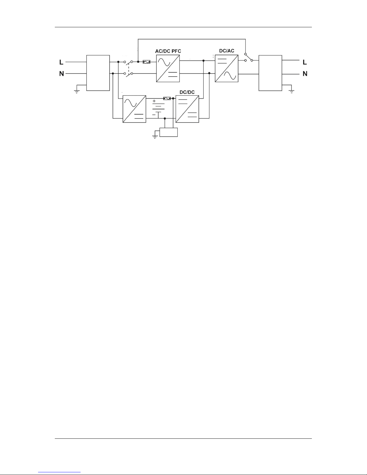
Fig. 1: Simplified block diagram of the UPS unit
The series of on-line UPS units with double conversion topology provides excellent
protection of the connected receivers, e.g. IT systems, and filters interferences in the
power supply line. The AC input may be corrected depending on the wave of the
power supply voltage by a high power factor correction circuit. Thanks to PWM
control, the input voltage may take the form of clean, stable sine.
If the mains parameters are faulty, the controller will shut down the AC/DC section
and promptly start the DC/DC unit, in order to maintain the uninterrupted operation of
the DC/AC section (inverter). Once the mains parameters are back to correct values,
the DC/DC section stops and AC/DC takes over again. This way, if the UPS is on,
the receiver is always protected by the inverter, with no interruptions.
The UPS features an external bypass to provide power to receivers directly from the
mains, in case the UPS is damaged.
The UPS has a built-in battery charger that will be charging the battery if the network
parameters are acceptable, except when the unit is in the back-up mode or in the
battery test mode.
BKF relay
Charger
Batteries
EMI
filter
DC bus
External battery
pack connector
EMI
filter
Bypass
relay
Page 6
Instruction manual for POWERLINE RT 1-3 kVA UPS units
2016-07-13 12:09 Technical Support, tel.: +48 61 6500 400 www.ever.eu
6
SAFETY INSTRUCTIONS AND RECOMMENDATIONS
A) General information
CAUTION! Before starting the procedures described in this manual,
please read the general safety instructions (including the instructions
found in this document), health & safety information, environmental
protection information and legal regulations that may apply. Always
observe the instructions and recommendations found in these
documents.
CAUTION! It is strictly forbidden for the user to perform any repairs, as
this would constitute a health hazard and may result in death. Any
repairs and replacement of batteries should be carried out only by
suitably qualified service technicians, with professional licences required
by law.
CAUTION! The unit should be operated and stored in conditions
complying with the requirements set in the specification (technical
documentation).
CAUTION! The device is completely disconnected from the mains only
when the power lead is removed from the mains socket (the plug is
removed from the mains socket).
CAUTION! The unit is equipped with an internal power source (batteries)
or it may operate in combination with a fixed, external source of power
(battery packs). Dangerous voltage may be present at the output
terminal(s), even if the unit has been disconnected from the mains.
Page 7
Instruction manual for POWERLINE RT 1-3 kVA UPS units
7 www.ever.eu Pomoc Techniczna, tel.: +48 61 6500 400 2016-07-13 12:09
CAUTION! The user should place warning labels on all remotely
installed primary isolation switches in order to warn electrical service
technicians that the circuit is powered by a UPS unit. The following (or
equivalent) text should be used on such warning labels:
DISCONNECT THE UPS SYSTEM BEFORE STARTING WORK ON THIS
CIRCUIT.
CAUTION! Opening the unit’s casing may result in electric shock.
CAUTION! Do not touch any electrical connectors, terminals and internal
metal elements unless power supply has been properly disconnected.
CAUTION! All openings and spaces designed to provide access to the
unit's electrical connections must remain covered (with applicable
covers). Failure to observe this requirement may create hazard
potentially resulting in injury or death for persons who touch such
connectors. It may also cause damage to the unit.
CAUTION! In the event of a short circuit, the resulting high current may
cause serious burns or scalds.
CAUTION! There are no user-serviceable parts inside the UPS unit.
CAUTION! The POWERLINE RT range of UPS units is not intended to
work directly with medical equipment, life-supporting equipment or any
other equipment that may have effect on health.
Page 8
Instruction manual for POWERLINE RT 1-3 kVA UPS units
2016-07-13 12:09 Technical Support, tel.: +48 61 6500 400 www.ever.eu
8
B) Installation information and requirements
CAUTION! The POWERLINE RT range of UPS units may only be
installed and maintained by suitably qualified service technicians.
CAUTION! Before installation of the UPS unit, the staff and users must
become familiar with the Health and Safety regulations when working
and handling electrical equipment up to 1 kV voltage.
CAUTION! Before connecting any cables or making any connections
within the UPS unit or in the electrical system, make sure there is no
dangerous voltage on electrical terminals and cables in the system.
CAUTION! The UPS may only be connected to a power system with
indicated rated voltage, with a suitable grounding connection installed.
The facility's electrical system to which the UPS unit is connected must
be fitted with overload and short-circuit protection.
CAUTION! Only TN-S or TN-C-S configuration is allowed on the UPS
unit's input side, and only TN-S configuration is allowed on the UPS
unit's output side.
CAUTION! No extension cords should be used for connecting the UPS
unit.
CAUTION! Installing a UPS unit in proximity of flammable materials or
substances is strictly prohibited!
Technicians must not work alone in hazardous conditions that may be dangerous
to health and/or life.
Shortly after the UPS unit has been moved from a cold environment to a warm
environment, moisture condensation may appear. The UPS unit must be
completely dry before installation and operation. The acclimatization time should
be at least 2 hours.
UPS units and battery packs must not be installed in humid environment.
Page 9

Instruction manual for POWERLINE RT 1-3 kVA UPS units
9 www.ever.eu Pomoc Techniczna, tel.: +48 61 6500 400 2016-07-13 12:09
UPS units and battery packs must not be installed in places where they would be
exposed to direct sunlight. They must not be installed near sources of heat.
Ventilation openings in the UPS unit casing must not be blocked. Always observe
distances to ventilation openings specified in the manual.
Before connecting the units, is necessary to check the condition of all leads,
cables, connectors, sockets and plugs, as well as that of the unit itself.
The unit must be connected to a power circuit with a PE grounding conductor.
Failure to observe this requirement may result in electric shock.
To reduce the risk of electric shock (in case the grounding cannot be checked),
the unit must be disconnected from the mains before installation or connecting to
other equipment. The power lead may only be connected again after making all
required connections.
The electric system's grounding conductor leads the leakage current away from
the receivers. The leakage currents of all loads connected to the UPS unit's
output are totalized in the UPS unit's power lead. The summary leakage current
may trigger protective devices (RCD) and result in disconnecting power to the
loads.
When connecting and disconnecting signal cables, all actions should be
performed with one hand only (if feasible). This is to avoid electric shock when
touching two surfaces with different electrical potentials.
Connecting leads should be placed so that people walking over them will not step
or trip on them.
An emergency power-off button (EPO), dedicated to the UPS system, should be
installed in the building's electrical system. This is to allow disconnecting, in
emergency, the UPS unit from the connected loads regardless of the mode in
which the UPS is operating.
To minimise the risk of fire, connections should only be made to circuits (electrical
systems) whose rating is adequate for the connected loads, with properly selected
overcurrent protection. Additionally, the breaker should feature at least a 3 mm
insulating air gap.
Page 10

Instruction manual for POWERLINE RT 1-3 kVA UPS units
2016-07-13 12:09 Technical Support, tel.: +48 61 6500 400 www.ever.eu
10
C) Operation of the UPS unit
Health and Safety regulations and guidelines specified in the UPS unit operating
manual must be observed when handling and operating the UPS unit.
All these instructions must be executed step by step. If any problems emerge
when executing the instructions given in this document, please contact EVER
service support (www.ever.eu).
Never disconnect the grounding at the UPS unit or at the terminals of the
building's electrical system, as this will disable the UPS unit's protective
grounding.
There may be voltage on the UPS unit's output terminals, even if the UPS is
disconnected from the building's electrical system (due to presence of power in
the unit's internal batteries and/or battery packs).
Liquids and foreign bodies must not be allowed to penetrate the UPS casing.
WARNING: This is a C3 category UPS. For commercial and industrial use in
secondary environment. Additional precautions or limitations in installation may be
required to prevent the emission of interferences.
D) Maintenance, repair and breakdown information
Dangerously high voltages are present in the UPS unit. Only qualified service
technicians may perform maintenance works.
CAUTION - Risk of electric shock! Even if the unit has been disconnected from
the mains (from terminals of the electrical power supply), parts inside the UPS
unit remain connected to the batteries, which may create hazards. Disconnect the
battery and/or battery packs before carrying out any servicing and/or
maintenance. Make sure there is no dangerous voltage on the DC circuit internal
elements.
WARNING: Only properly authorized and qualified service technicians who have
legally required protection gear may replace batteries.
CAUTION - Risk of electric shock! Dangerous voltage may be present between
the battery circuit and the grounding point!
Batteries have high short-circuit current and pose a risk of electric shock. The
following precautions should be taken when working with batteries:
- remove jewelry, watches, rings and other metal items,
- only use tools with insulated handles.
Page 11
Instruction manual for POWERLINE RT 1-3 kVA UPS units
11 www.ever.eu Pomoc Techniczna, tel.: +48 61 6500 400 2016-07-13 12:09
When replacing batteries, always use the same type and the same number of
batteries. Using batteries of incorrect type may result in explosion.
Always dispose of used batteries according to relevant instructions.
WARNING: Disposing of batteries in a fire may result in explosion.
WARNING: Opening or damaging batteries may cause electrolyte to leak;
electrolyte is harmful to skin and eyes, and may also be toxic.
To avoid the danger of fire and damage to the mains or power supply system,
always replace broken or blown fuses with fuses of the same type and
parameters.
Disconnect the device from the mains before cleaning. Do not use liquid or
sprayed cleaning agents.
UPS units may only be disassembled by suitably qualified service technicians.
E) Transport and packaging requirements
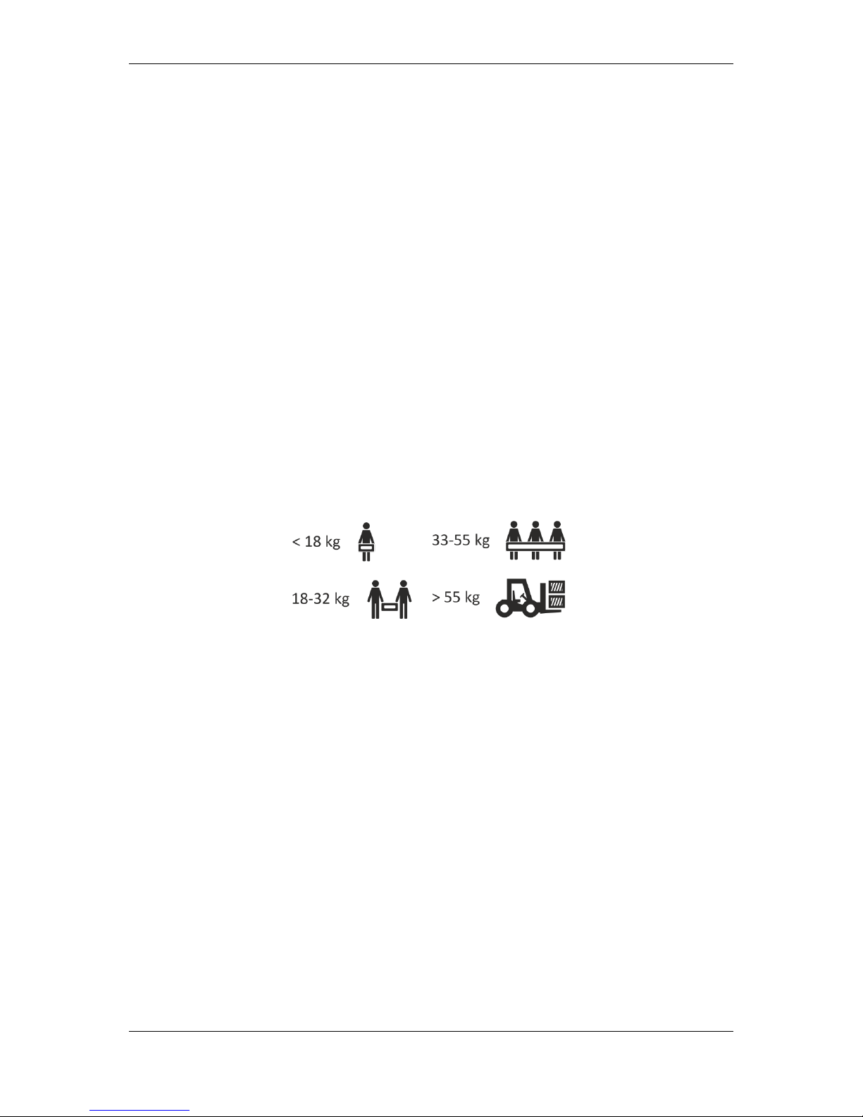
Exercise particular care when transporting the equipment, due to its heavy weight.
Heavy equipment must be moved by at least two or more persons.
UPS units may be transported only in their original packaging boxes to ensure
adequate protection against shocks, vibrations and impact.
The unit should be operated and stored in conditions meeting the requirements in
the product specification. UPS units must be stored in a dry room with suitable
ventilation.
If a UPS is to be stored over a longer period of time, its batteries must be
recharged at least every 6 months. The recharging procedure must always be
recorded and documented.
Always make sure to check the date when recharging is due. Do not use the UPS
unit if the deadline has passed and the batteries have not been recharged. In
such cases always contact service support.
Page 12
Instruction manual for POWERLINE RT 1-3 kVA UPS units
2016-07-13 12:09 Technical Support, tel.: +48 61 6500 400 www.ever.eu
12
TECHNICAL DESCRIPTION
UNPACKING THE PRODUCT
Keep the packaging for future transportation operations.
The UPS unit must be properly examined upon delivery or handover. Although the
product is solidly packaged, the appliance could have been damaged due to shocks
experienced during transport. If any of the units is damaged during transportation, a
complaint for transportation damage should be filed. Should any product damage be
discovered upon receiving the product, the carrier or the vendor must be notified
immediately (a complaint should be filed).
CAUTION! The product is supplied with the batteries connected.
CAUTION! Water vapor may condensate on the UPS unit's elements if
packaging is removed from the device in low temperatures. Do not install
the UPS until its interior and housing are completely dry (electric shock
risk).
CAUTION! The appliance is heavy. Considerable care is required when
it is being unpacked or moved.
Exercise caution when moving or unpacking the device. Refrain from
unpacking its individual elements until they are required for installation.
Page 13

Instruction manual for POWERLINE RT 1-3 kVA UPS units
13 www.ever.eu Pomoc Techniczna, tel.: +48 61 6500 400 2016-07-13 12:09
What’s in the box?
Check carefully the contents of the packaging. The packaging should contain:
a) UPS POWERLINE RT 1000, 2000:
- the UPS unit,
- 2 sets of Tower supports for installing the unit vertically,
- 1 x power cord CEE7/7 - IEC 320 C13, 10A,
- 2 x power cords IEC C13 - IEC C14 10A,
- 1 x USB cable,
- 1 x RS232 cable (communication with PC),
- 1 x RS232 cable (status signaling),
- warranty card,
- user's guide.
b) UPS POWERLINE RT 3000:
- the UPS unit,
- 2 sets of Tower supports for installing the unit vertically,
- 1 x power cord CEE 7/7 - IEC 320 C19, 16A,
- 2 x power cords IEC C13 - IEC C14 10A,
- 1 x power cord IEC C19 - IEC C20 16A,
- 1 x USB cable,
- 1 x RS232 cable (communication with PC),
- 1 x RS232 cable (status signaling),
- warranty card,
- user's guide.
c) Rack Kit for installing UPS units / battery modules in rack cabinets
(optional):
- a set of elements for installing the unit in a rack cabinet:
- 2 front rack supports with installation accessories,
- 2 sliding rack guides (with profiles and their screws),
- a printed manual with pictures for installing UPS units / battery modules in rack
cabinets, with instructions for placing the - LCD panel horizontally.
Page 14

Instruction manual for POWERLINE RT 1-3 kVA UPS units
2016-07-13 12:09 Technical Support, tel.: +48 61 6500 400 www.ever.eu
14
d) SNMP card (optional):
- SNMP card,
- 1 x cable RJ - RS232,
- a CD with software,
- a warranty card.
e) Battery module POWERLINE RT 1000 & 2000/3000:
- 1 battery module,
- 1 power cord,
- 1 battery module detection cable for automatic detection of the number of
connected modules (RJ11),
- 2 sets of Tower supports for installing the unit horizontally,
- an element for linking the battery module with another module or the UPS,
- a warranty card.
Page 15
Instruction manual for POWERLINE RT 1-3 kVA UPS units
15 www.ever.eu Pomoc Techniczna, tel.: +48 61 6500 400 2016-07-13 12:09
ELEMENTS OF THE UPS - REAR PANEL
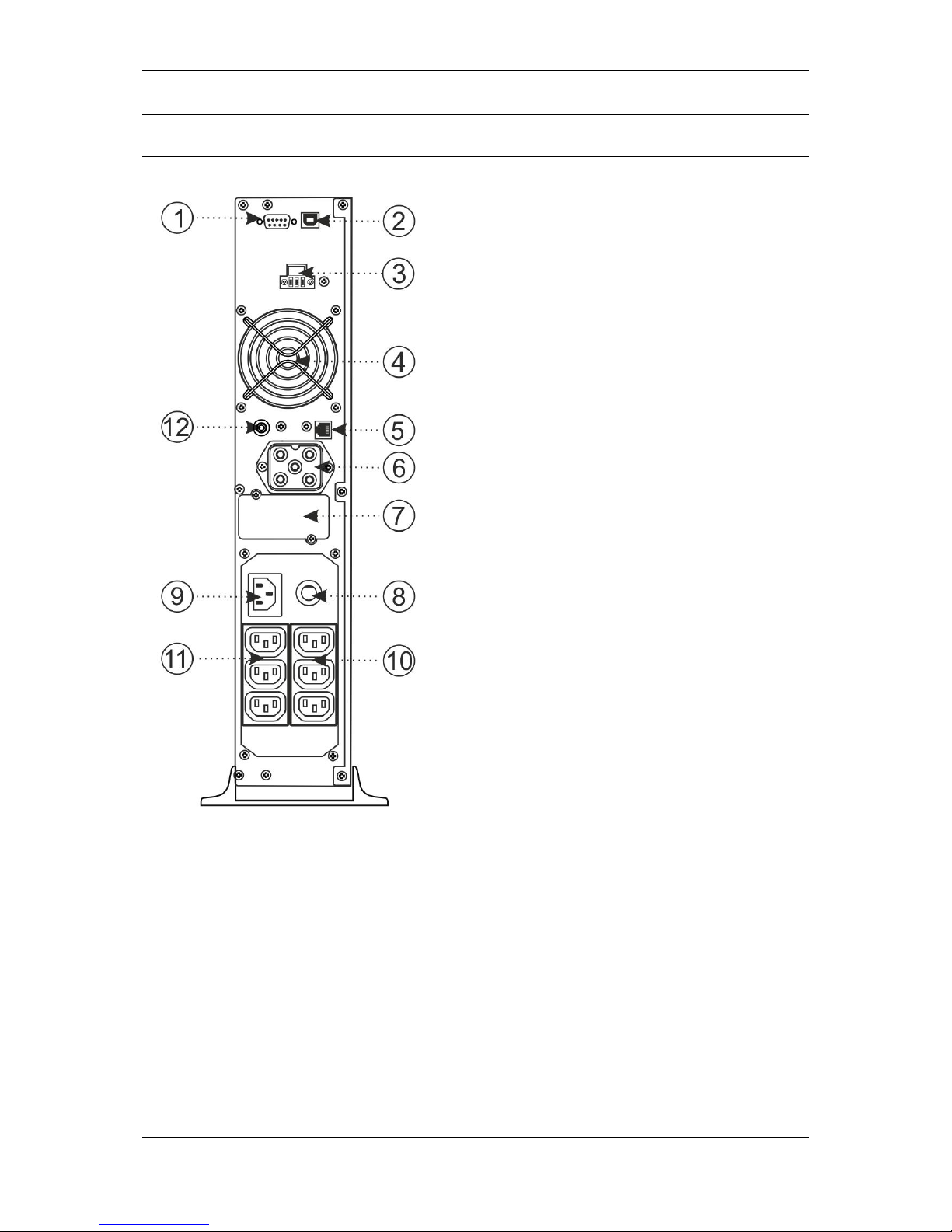
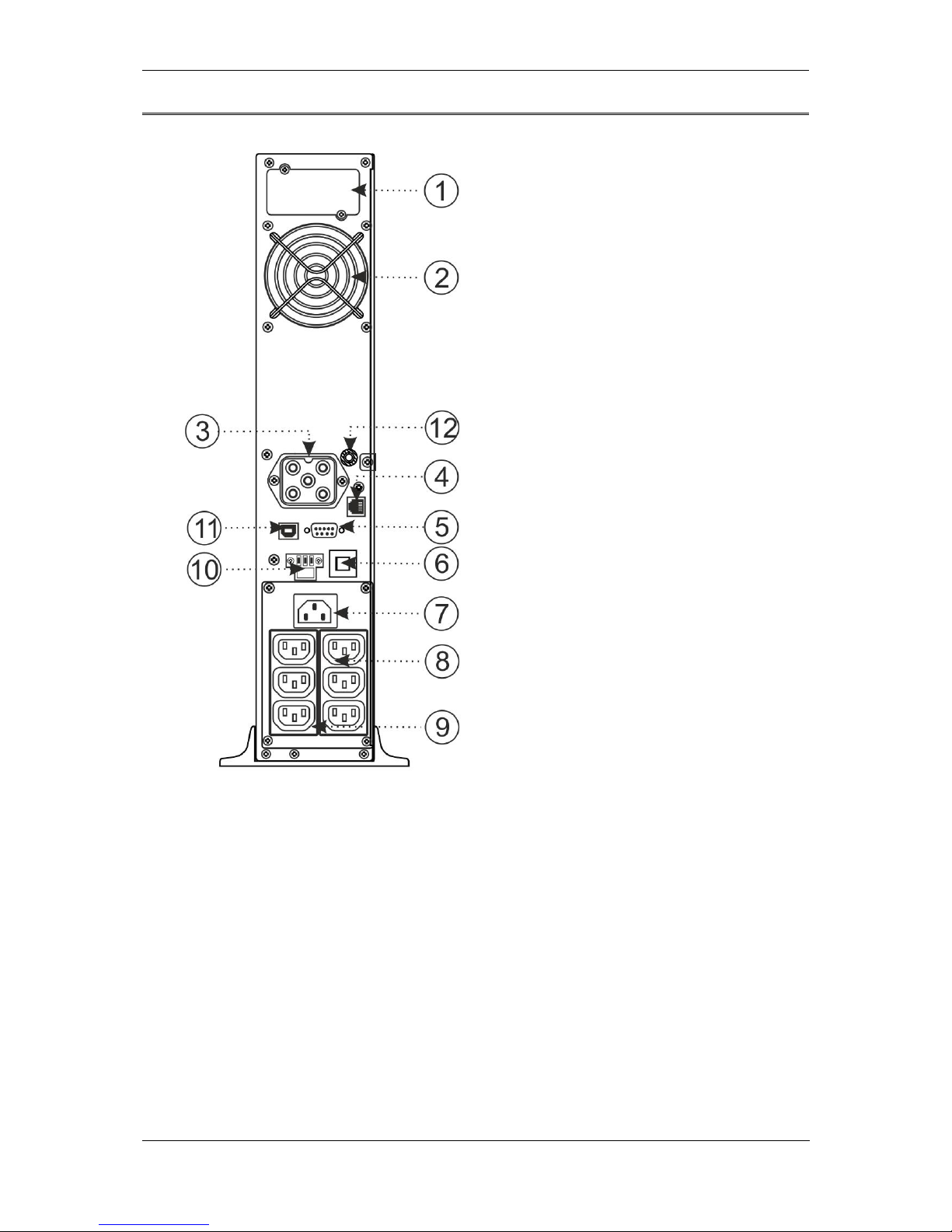
POWERLINE RT 1000
1. RS232 port
2. USB port
3. ROO/EPO terminals
4. Fan
5. RJ11 port – battery module detection
6. Power supply socket for connecting an
external battery module
7. SNMP card slot
8. Input circuit safeguard
– automatic fuse
9. Power supply input socket
10. Non-controlled output socket 10A
11. Controlled output sockets
(group 1 and 2) 10A
12. Earthing clamp
Fig. 2: View of the rear panel elements in POWERLINE RT 1000 UPS.
Page 16
Instruction manual for POWERLINE RT 1-3 kVA UPS units
2016-07-13 12:09 Technical Support, tel.: +48 61 6500 400 www.ever.eu
16
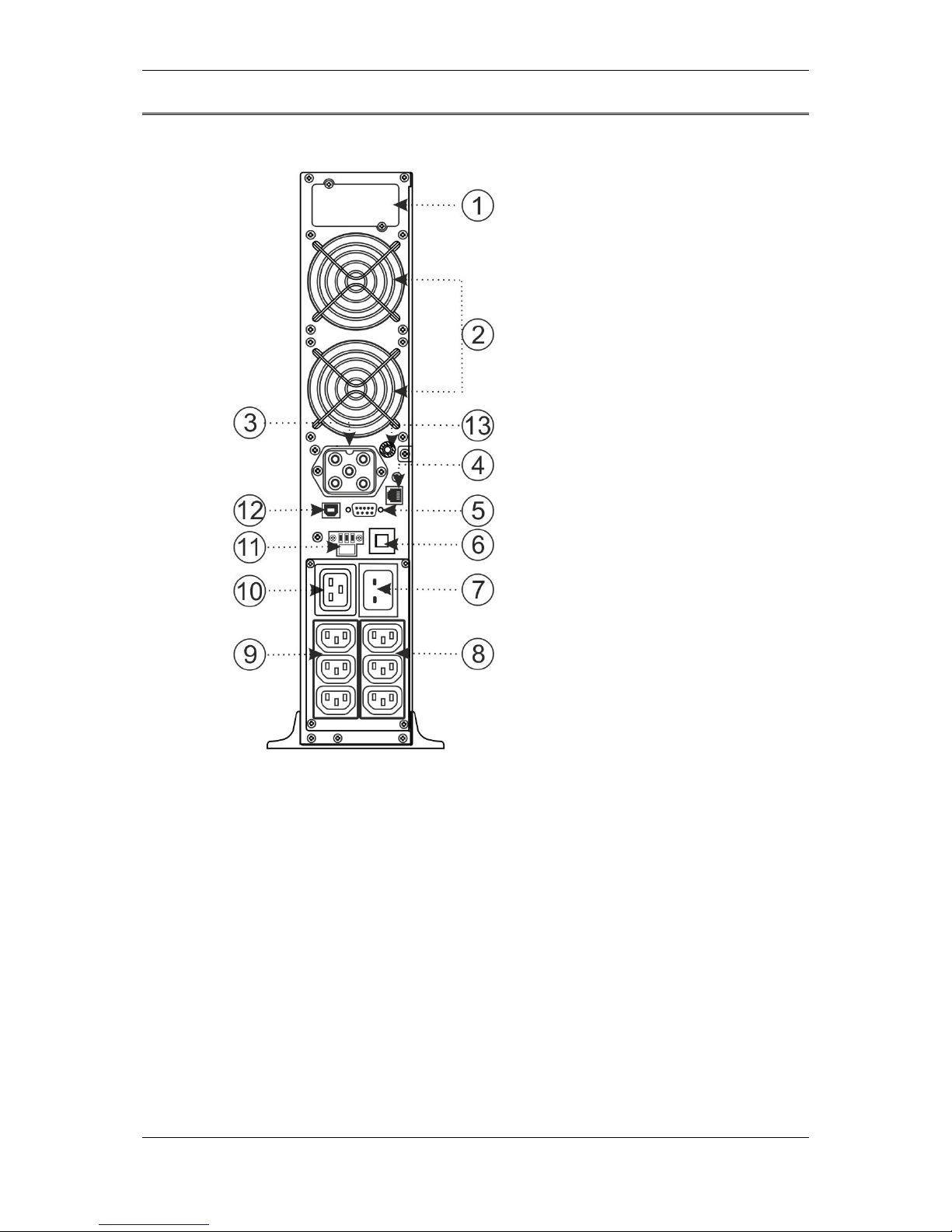
POWERLINE RT 2000
1. SNMP card slot
2. Fan
3. Power supply socket for
connecting an external battery
module
4. RJ11 port – battery module
detection
5. RS232 port
6. Input circuit safeguard
- automatic fuse
7. Power supply input socket
8. Non-controlled output socket 10A
9. Controlled output sockets
(group 1 and 2) 10A
10. ROO/EPO terminals
11. USB port
12. Earthing clamp
Fig. 3: View of the rear panel elements in POWERLINE RT 2000 UPS.
Page 17
Instruction manual for POWERLINE RT 1-3 kVA UPS units
17 www.ever.eu Pomoc Techniczna, tel.: +48 61 6500 400 2016-07-13 12:09
POWERLINE RT 3000
1. SNMP card slot
2. Fan
3. Fan
4. Power supply socket for
connecting an external
battery module
5. RJ11 port – battery
module detection
6. RS232 port
7. Input circuit safeguard
– automatic fuse
8. Power supply input socket
9. Non-controlled output
socket 10A
10. Controlled output sockets
(group 1 and 2) 10A
11. Output socket 16A
12. ROO/EPO terminals
13. USB port
14. Earthing clamp
Fig. 4: View of the rear panel elements in POWERLINE RT 3000 UPS.
Page 18
Instruction manual for POWERLINE RT 1-3 kVA UPS units
2016-07-13 12:09 Technical Support, tel.: +48 61 6500 400 www.ever.eu
18
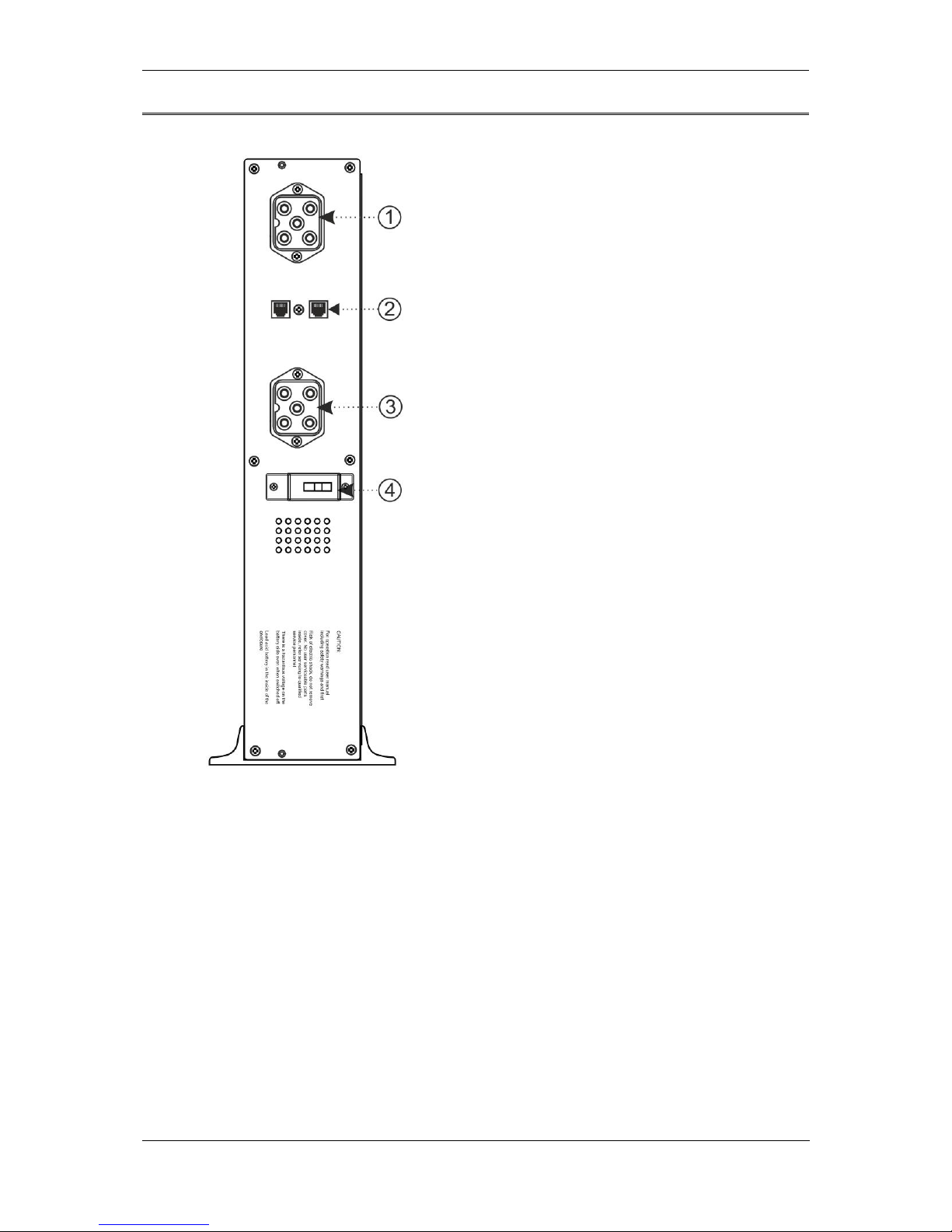
Battery module POWERLINE RT 1000
1. Battery module power supply socket
2. RJ11 port – battery module detection
3. Battery module power supply socket
4. Fuse 70 A / 80 V DC
Fig. 5: View of the rear panel elements in POWERLINE RT 1000 UPS battery module.
Page 19
Instruction manual for POWERLINE RT 1-3 kVA UPS units
19 www.ever.eu Pomoc Techniczna, tel.: +48 61 6500 400 2016-07-13 12:09
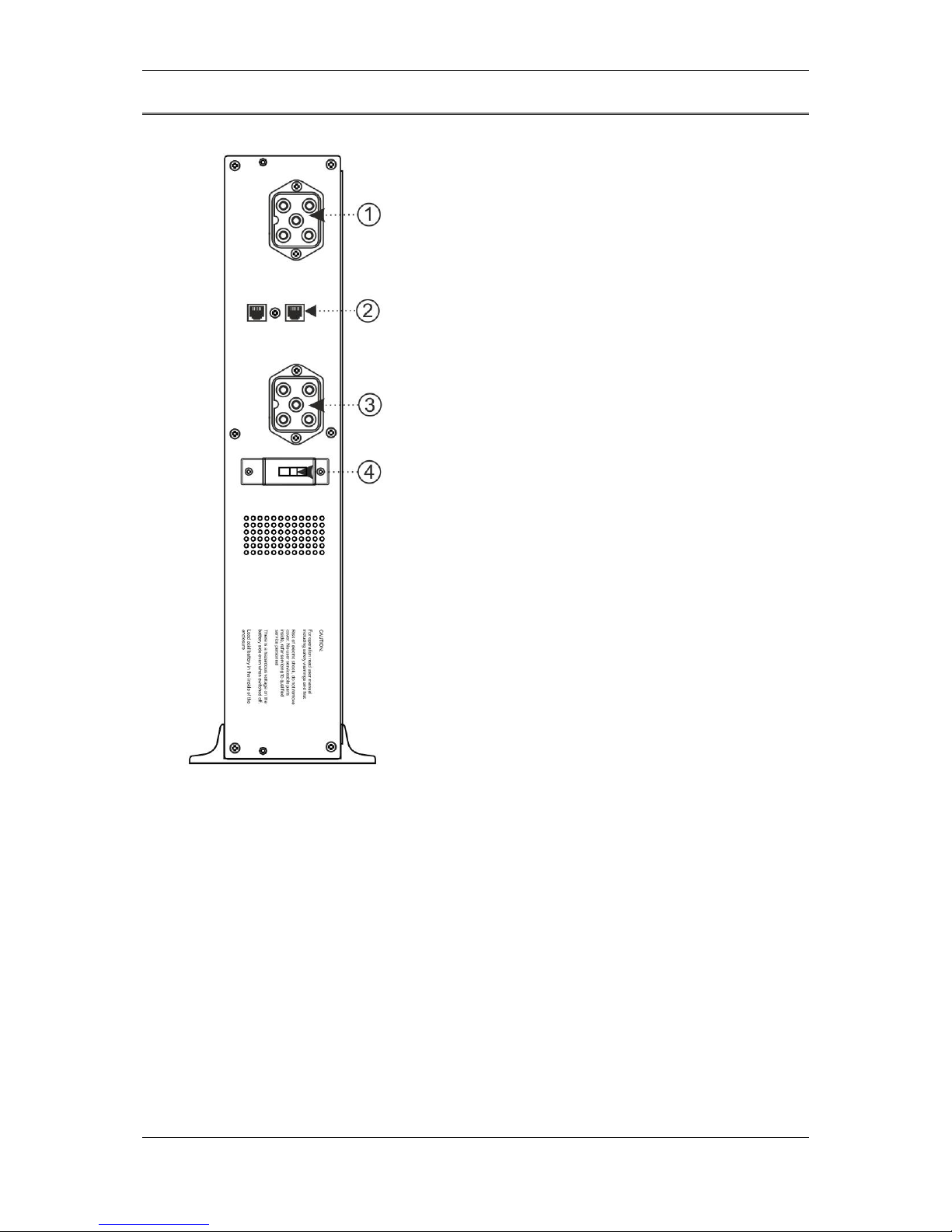
Battery module POWERLINE RT 2000/3000
1. Battery module power supply socket
2. RJ11 port – battery module detection
3. Battery module power supply socket
4. Fuse 70 A / 80 V DC
Fig. 6: View of the rear panel elements in POWERLINE RT 2000 / 3000 UPS battery module.
Page 20
Instruction manual for POWERLINE RT 1-3 kVA UPS units
2016-07-13 12:09 Technical Support, tel.: +48 61 6500 400 www.ever.eu
20
HOW IT WORKS
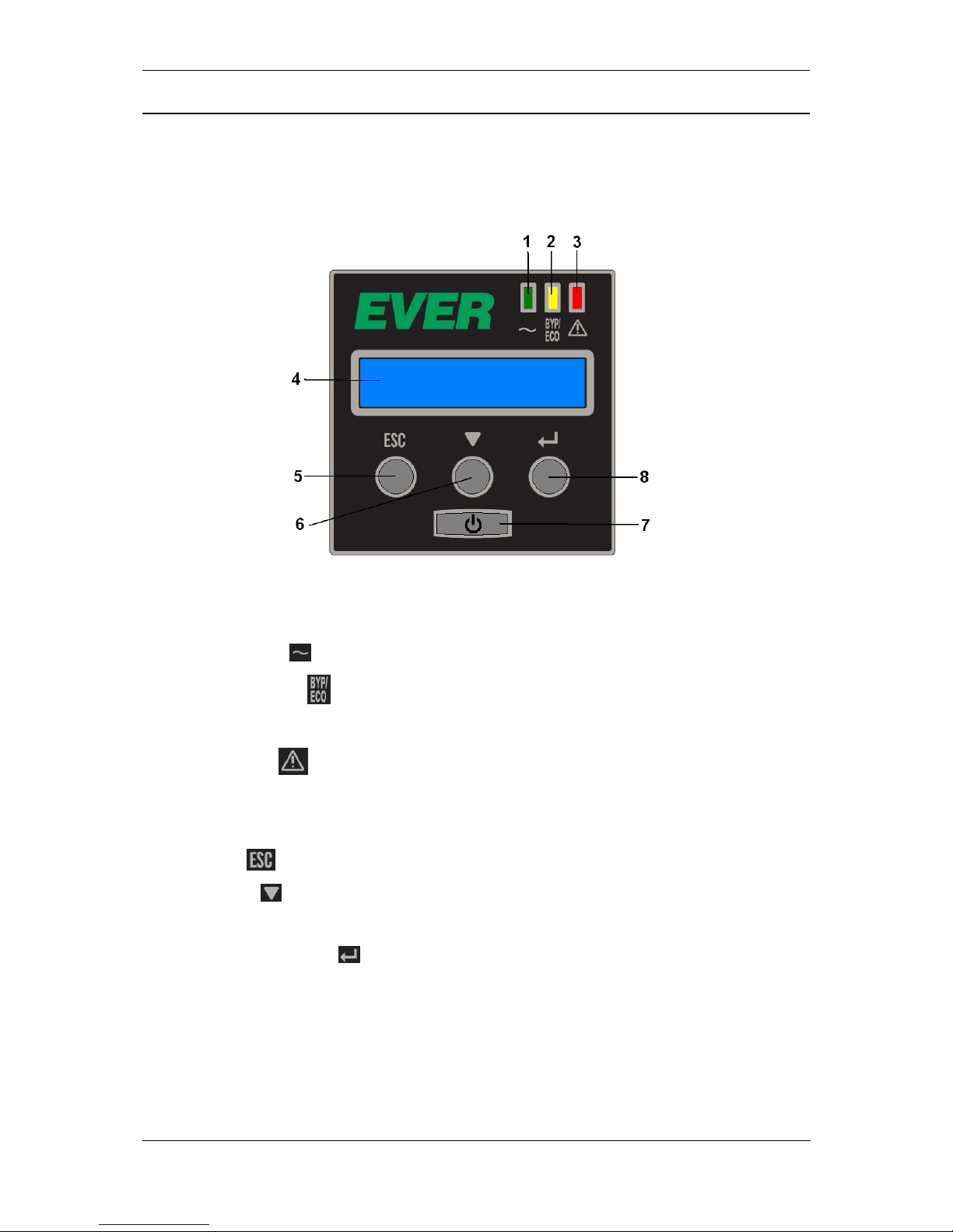
Fig. 7 shows POWERLINE RT front panel elements. The UPS features a 4-key
control panel, an LCD display and signaling LEDs.
Fig. 7: View of the front panel elements in POWERLINE RT UPS.
1. Green LED - input voltage is available.
2. Orange LED - signalization of bypass and ECO modes, and warnings
displayed on the LCD, e.g. in overload conditions.
3. Red LED - signalization of the most critical messages related to the unit's
operation, e.g. short circuit, internal error.
4. LCD display
5. Exit -
6. Scroll -
7. Start / shut down key. Back-up mode LED (key with green backlight)
8. Confirmation key
Page 21

Instruction manual for POWERLINE RT 1-3 kVA UPS units
21 www.ever.eu Pomoc Techniczna, tel.: +48 61 6500 400 2016-07-13 12:09
Table 1 presents the description of light signals for various states of operation of the
UPS; table 2 presents the description of warnings and errors.
Table 1. Description of LED colors
LED number
1 2 3
7
Stand-by mode - correct voltage in the input
●
Stand-by mode - no correct voltage in the input
Bypass mode (output on)
●
●
Mains mode
●
●
Back-up mode
●
ECO Mode
●
●
Critical error mode
●
● Continuous light
Table 2. Warnings and errors
Displayed information
Description
EPO RELEASE
UPS stopped working, because EPO was activated (remote power
supply off)
BATT. ERROR
CALL SERVICE
Battery error detected. Check batteries.
OVERLOAD
CHECK OUTPUT
Inverter overload detected (mains power or backup mode)
BYPASS OVERLOADED
OUTPUT W/O PROT.
Overload detected when the device is in the bypass mode.
FAN FAILURE
Fan failure detected
CHARGER
VOLT. TOO HIGH
The charger supplies too high voltage (internal error)
DC BUS
VOLT. TOO HIGH
DC voltage in the DC bus is too high (internal error)
DC BUS
VOLT. TOO LOW
DC voltage in the DC bus is too low (internal error)
DC BUS
UNSTABLE
DC voltage in the DC bus is unstable (internal error)
INVERTER
VOLT. TOO HIGH
The inverter supplies too high voltage (internal error)
INVERTER
VOLT. TOO LOW
The inverter supplies too low voltage (internal error)
SHORT CIRCUIT
CHECK OUTPUT
Inverter short circuit (internal error)
PHASE ERROR
CHECK AC INPUT
Inverted direction of phase cables detected. Check the layout of input
connections
OVERHEATING
REDUCE TEMP.
UPS elements' temperature too high
Page 22

Instruction manual for POWERLINE RT 1-3 kVA UPS units
2016-07-13 12:09 Technical Support, tel.: +48 61 6500 400 www.ever.eu
22
MENU AND FUNCTIONS
Functions available in the menu and submenu are described below.
DISPLAY PANEL
Function
Displays current operation mode, information about warnings and errors
MENU 1.- STATUS
Function
Displays input and output values (voltage, frequency, load...)
MENU 2.- EVENTS
Function
Displays five most recent events (errors, warnings...)
1
EPO RELEASE
UPS stopped working, because EPO was activated (remote power supply off)
2
BAT. ERROR
Battery error detected
3
INVERTER
OVERLOAD
Inverter overload detected (mains or backup mode)
4
BYPASS
OVERLOAD
Overload detected when the device is in the bypass mode.
5
FAN ERROR
Fan error detected
6
CHARGER
VOLT. TOO HIGH
The charger supplies too high voltage (internal error)
7
DC BUS
VOLT. TOO HIGH
DC voltage in the DC bus is too high (internal error)
8
DC BUS
VOLT. TOO LOW
DC voltage in the DC bus is too low (internal error)
9
DC BUS
UNSTABLE
DC voltage in the DC bus is unstable (internal error)
10
INVERTER
VOLT. TOO HIGH
The inverter supplies too high voltage (internal error)
11
INVERTER
VOLT. TOO LOW
The inverter supplies too low voltage (internal error)
12
INVERTER
SHORT CIRCUIT
Inverter short circuit (internal error)
13
PHASE ERROR
CHECK AC INPUT
14
OVERHEATING
Device overheating
15
NO EVENTS
No events in the register
The LCD displays shows five most recent events. They are numbered from 1 to 5, where 1 is
most recent, and 5 oldest event. Event 1 is displayed as first, and events from 2 to 5 are
displayed when the forward button is pushed. After displaying the event type, the next screen
tells you when it occurred relative to the device's working time. This is not a calendar date.
The time follows the format: DDDD:HH:MM:SS, where DDDD is the consecutive day of the
device's work, HH – hours, MM – minutes, SS – seconds. The next screen is the next event.
Page 23

Instruction manual for POWERLINE RT 1-3 kVA UPS units
23 www.ever.eu Pomoc Techniczna, tel.: +48 61 6500 400 2016-07-13 12:09
MENU 3. - CONTROL
Submenu
Function
3.1
BATTERY TEST
After selecting this option, the battery test is performed
3.2
MANUAL BYPASS
ON / OFF
Switching the UPS unit to bypass mode and back
3.3
SEC. 1 OUTPUTS
ON / OFF
Section 1 outputs on / off (first group of controllable output sockets)
3.4
SEC. 2 OUTPUTS
ON / OFF
Section 2 outputs on / off (second group of controllable output sockets)
MENU 4. - SETUP
Submenu
Function
4.1
LANGUAGE
SELECTION
Language selection (English, Spanish, Italian, French, Polish, Portuguese,
German)
4.2
SOUND ALARM
Sound alarm activated / deactivated (buzzer)
4.3
OUTPUT VOLT.
SETTING
Selection of output voltage (200 V, 208 V, 220 V, 230 V or 240 V)
4.4
OUTPUT FREQ.
(IN STAND. MODE)
Selection of rated output frequency 50 Hz or 60 Hz (only in frequency conversion
mode)
4.5.
FREQ. CONVERSION
(IF UPS IS OFF)
Activation / deactivation of frequency conversion mode (UPS must be in standby
mode)
4.6
SEC. 1 OUTPUTS
SETTING
Selection of battery charging level (75%, 50%, 25% or 0%) below which output 1
(first group of controlled output sockets) is deactivated automatically
4.7
SEC. 2 OUTPUTS
SETTING
Selection of the battery charging level (75%, 50%, 25% or 0%) below which output
2 (second group of controlled output sockets) is deactivated automatically
4.8
COLD START
ON / OFF
Cold start on / off (UPS starts without power from the mains)
4.9
START AFTER
DISCHARGING
ON / OFF
Automatic restart function on / off (UPS starts automatically after autonomous
operation time expires, when power in the mains is back)
4.10
ECO MODE
ON / OFF
ECO mode on / off
4.11
PHASE DETECTION
ON / OFF
Phase detection function on / off (detection of incorrect order of input cables)
4.12
AUTOMATIC
BATTERY TEST
Setting of automatic battery test (every day, every week, every month, ...)
4.13
BAT. DIS. LEVEL
ALARM SETTING
Selection of battery charge level (75%, 50%, 25% or 0%) under which signal
"Battery low level" is generated.
MENU 5. - INFORMATION
Function
Displays rated power of the UPS, software version and UPS working time.
Page 24
Instruction manual for POWERLINE RT 1-3 kVA UPS units
2016-07-13 12:09 Technical Support, tel.: +48 61 6500 400 www.ever.eu
24
INSTALLATION
CAUTION! Before installation of the UPS unit, the user must get familiar
with the safety instructions in the present chapter and with general health
and safety (H&S) recommendations.
CAUTION! Do not install or operate the UPS if water condensation is
present; this may happen if the UPS is moved directly from cold
environment into warm environment. The UPS unit must be completely
dry before installation and operation. The acclimatization time should be
at least 2 hours. Otherwise there is risk of electrocution!
CAUTION! Install the unit in a well ventilated place. Do not block
opening in the UPS housing, maintain proper space all around the unit to
ensure correct air circulation.
CAUTION! Install the unit and its cable following relevant local
regulations.
CAUTION! The UPS must be grounded. Before connected power supply
cables to the building's electric system terminal, make sure the
grounding connection is not faulty. If there are external battery packs for
the UPS, the compensating grounding connection with the main UPS
unit is done with the power supply cables of the modules.
CAUTION! The electric system design must allow disconnecting the
point of connection between the UPS to the mains, e.g. by switching the
electric system's overcurrent breakers.
CAUTION! When connecting several battery modules in parallel, always
observe the rule "same voltage, same type".
Page 25
Instruction manual for POWERLINE RT 1-3 kVA UPS units
25 www.ever.eu Pomoc Techniczna, tel.: +48 61 6500 400 2016-07-13 12:09
MECHANICAL INSTALLATION
The UPS units and battery modules can be installed in rack enclosures with depth up
to 1200 mm. The optional Rack Kit is required to do this. The kit contains an
installation manual and a description of changing the position of the LCD panel. By
default, the UPS unit is offered in Tower version (for vertical operation).
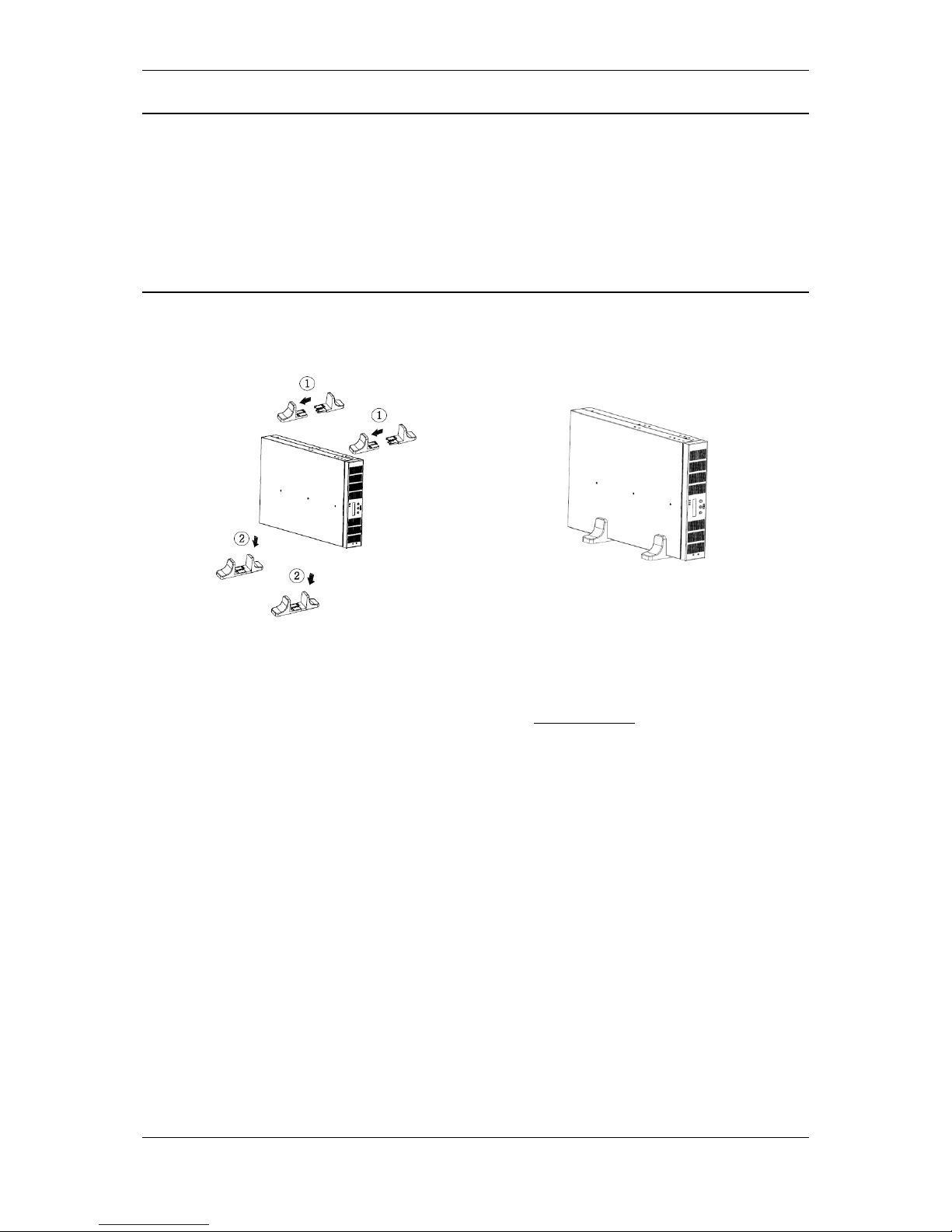
INSTALLATION OF THE UPS AND BATTERY MODULES VERTICALLY
1. Install two sets of supports (delivered with the UPS) and place the UPS between
those supports, as shown in the figures.
Fig. 8. Installation of the UPS vertically
The UPS may be installed horizontally; the information can be found in the abridged
manual, available in the product's packaging or at www.ever.eu.
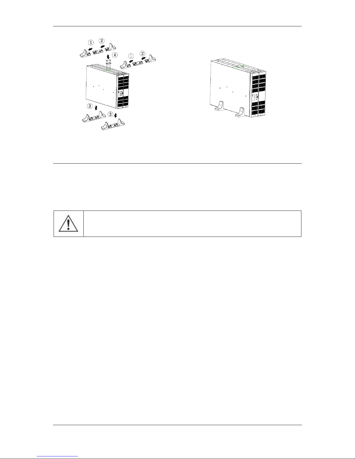
2. Installation of UPS Plus with the external battery pack
Assemble two sets of supports with the attached distance element and place the
UPS between those supports as shown in Fig. 9. Secure the UPS and the battery
pack with the supplied plates and screws.
Page 26
Instruction manual for POWERLINE RT 1-3 kVA UPS units
2016-07-13 12:09 Technical Support, tel.: +48 61 6500 400 www.ever.eu
26
Fig. 9. Installation of the UPS with a battery pack
ELECTRICAL SYSTEM
The mains socket the UPS is to be connected to should be located near the battery
and should be easily accessible.
No extension cords should be used for connecting the UPS unit.
CAUTION! The UPS is disconnected from the mains only when the
power lead is removed from the mains socket.
Due to the type and placement of the fuses in the power supply unit, the protection
systems in the building's electric system are used as one of the protection levels.
This is necessary to ensure short circuit protection of the power supply unit.
The parameters of the building's electric wiring system protection should be selected
to meet the requirements of the load connected to the wiring system and the type the
load. In extreme cases, different characteristics of the building’s and the UPS unit’s
electrical protection systems may result in the former system being activated earlier.
Page 27
Instruction manual for POWERLINE RT 1-3 kVA UPS units
27 www.ever.eu Pomoc Techniczna, tel.: +48 61 6500 400 2016-07-13 12:09
Input installation
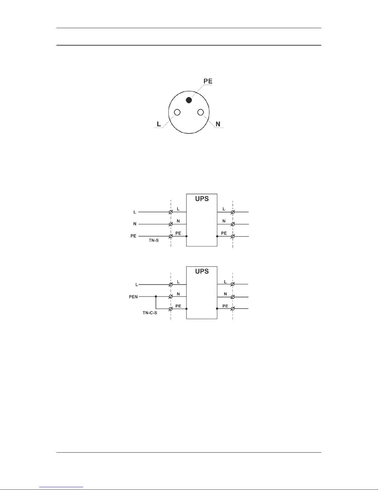
To make sue the UPS connection is made according to the manual, a proper pin
configuration of the power socket must be ensured (Fig. 10).
Fig. 10: Power socket pin configuration
Fig. 11 shows correct methods of connecting the UPS to various types of mains (TNS or TN-C-S) with different earthing systems (PE conductor connections).
Fig. 11: UPS input installation
LOAD
LOAD
OUTPUT
OUTPUT
INPUT
INPUT
POWER SOURCE
POWER SOURCE
Page 28
Instruction manual for POWERLINE RT 1-3 kVA UPS units
2016-07-13 12:09 Technical Support, tel.: +48 61 6500 400 www.ever.eu
28
Output installation
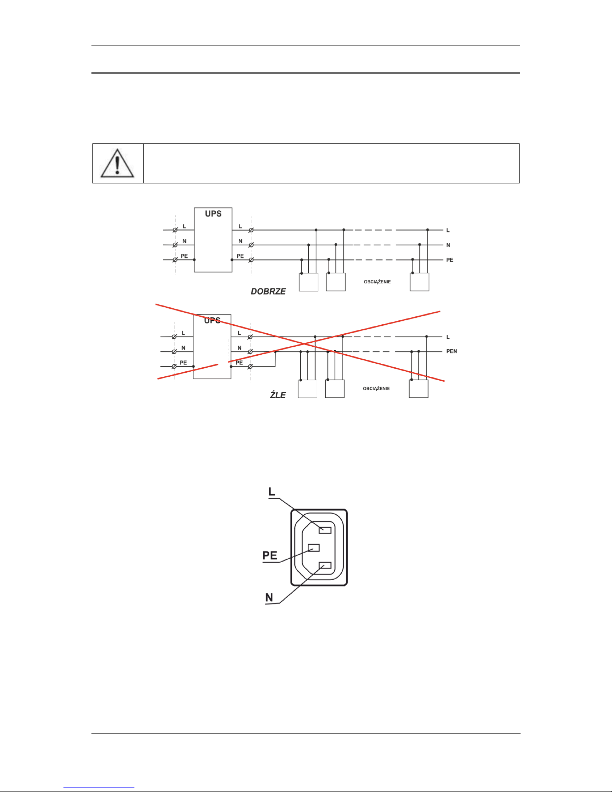
Although two types of pin configuration are allowed for the input side, the output
installation must be done specifically according to this manual, to prevent UPS
damage. Fig. 12 shows the diagrams of correct and incorrect output configurations.
CAUTION! Only TN-S configuration is allowed for the UPS output
installation.
Fig. 12: UPS output installation
Fig. 13 shows POWERLINE RT UPS output socket pin configuration.
Fig. 13: Output socket pin configuration
POWER SOURCE
POWER SOURCE
INPUT
INPUT
OUTPUT
OUTPUT
Page 29

Instruction manual for POWERLINE RT 1-3 kVA UPS units
29 www.ever.eu Pomoc Techniczna, tel.: +48 61 6500 400 2016-07-13 12:09
POWER CONNECTIONS
Connecting an external battery module
WARNING: Before connecting a battery pack to the UPS make sure that
the battery pack's safeguard is OFF. Once the electric connection with
the UPS is established, switch the safeguard to ON.
CAUTION: Each battery module contains two battery connectors. The first battery
pack is connected to the UPS with a cabled attached to the product. Each additional
battery pack should be connected with its cable to the previous module.
External battery packs (if they are to be used) should be connected to the UPS
before the unit is connected to the mains.
Follow this procedure to connect external battery packs:
1. Switch battery pack circuits safeguards (in each battery pack) to OFF.
2. Connect the battery pack and the UPS with the supplied cable.
3. Connect the next battery pack to the already connected one.
4. "Daisy chain" all battery packs.
5. Connect the battery pack detection cable to the RJ11 port in the back of the UPS
and the RJ11 port in the back of the first battery pack.
6. Connect the battery pack detection cable to an RJ11 port in the back of the first
battery module and the RJ11 port in the back of the second battery pack.
7. "Daisy chain" the remaining battery packs with the supplied detection cables.
8. Switch circuits safeguards on all battery packs to ON.
Once all external battery packs are connected, make all necessary connections
between inputs and outputs as described below.
Page 30
Instruction manual for POWERLINE RT 1-3 kVA UPS units
2016-07-13 12:09 Technical Support, tel.: +48 61 6500 400 www.ever.eu
30
Connecting the UPS to the mains
1. Connect the input power supply cable to the AC socket.
CAUTION: The batteries start charging once input power supply is detected.
2. Connect a receiver to the UPS. It is recommended that the most critical devices
are connected to the main outputs and the less important ones to the controlled
outputs.
CAUTION: The user's panel can be used to set the threshold of
disconnecting the controlled output sockets. In this way power can be
saved for higher priority receivers.
3. Once all connections have been made, follow the instructions in the next chapter
(Operation) to start the UPS and the external battery packs.
UPS START-UP
Initial procedure of starting the UPS up
1. When the UPS is used for the first time, make sure the unit is connected to the
mains and then press and hold the ON/OFF button until a sound signal is heard.
2. The UPS will react by emitting several sound signals and the MAINS MODE
message and UPS load level are displayed on the LCD. The connected receiver
are supplied with power.
Usual procedure of starting the UPS up
1. Press and hold the ON/OFF button until a sound signal is heard.
2. The UPS will react by emitting several sound signals and LEDs will flash up.
3. If the the AC mains is connected to the UPS, a green LED (1) will light up. The
MAINS MODE message will be displayed on the LCD, which means output
sockets are supplied with power.
4. If there is no input power supply (the green LED is off) and the cold start function
is on, the UPS unit's back-up mode LED will light up to indicate that the receiver
is drawing power from the battery. The BACK-UP MODE message will be
displayed on the LCD, along with estimated time of autonomous operation.
Page 31
Instruction manual for POWERLINE RT 1-3 kVA UPS units
31 www.ever.eu Pomoc Techniczna, tel.: +48 61 6500 400 2016-07-13 12:09
CAUTION: If the OVERLOAD message is displayed on the LCD, this
means that too many receivers have been connected to the UPS. If only
one receiver is connected to the UPS and the OVERLOAD message is
displayed on the LCD, this means that the receiver's power demand
exceeds the UPS unit's rating and a more powerful UPS should be used.
CAUTION: If the UPS fails to react like described above, please refer to
the "Typical Problem" chapter.
UPS Shut-down procedure
Press and hold the ON/OFF button until the UPS switches to stand-by mode and
then disconnect the mains. The UPS will disconnect all outputs and switch off.
DESCRIPTION OF OPERATION OF THE UPS
The POWERLINE UPS unit is a modern electronic device, an autonomous source of
~230 V sine voltage. This unit belongs to a series of uninterruptible ONLINE class
UPS devices whose characteristic feature is constant transformation of power. This
feature allows POWERLINE units to condition the power in the output line.
Regardless of voltage fluctuations and distortions on the input, the POWERLINE
units generate, throughout operation, sinusoidal waveform of ~230 V in the output.
MODES OF OPERATION
Stand-by mode
The UPS is logically on, the output is disconnected (voltage is not present).
Bypass mode
The bypass mode means that the UPS is powering the receiver directly from the
bypass circuit, without regulating the power. If the controller detects incorrect power
supply parameters it will disconnect the input and go into stand-by mode to protect
the receiver. The user may force the bypass mode with keys on the UPS unit's front
panel. When the unit is in bypass mode, the control panel or the software may be
used to adjust most of the UPS unit's settings.
To switch the unit into the bypass mode go to menu 3 (CONTROL) and then to
submenu SET BYPASS and select SWITCH TO BYPASS MODE or press the
Page 32
Instruction manual for POWERLINE RT 1-3 kVA UPS units
2016-07-13 12:09 Technical Support, tel.: +48 61 6500 400 www.ever.eu
32
confirmation button for 6 seconds. To revert to the mains mode follow the same
procedure, by select SWITCH TO MAINS MODE. If the UPS is in the stand-by mode
or in the frequency conversion mode, the function of switching to the bypass mode is
not available.
Mains mode
In the mains mode the input current is rectified / converted by the AC/DC section and
then converted into stable output current by the DC/AC section and then supplied to
the receivers. If the mains parameters become incorrect, the UPS will switch, without
interruptions, into the back-up mode.
Back-up mode
In the back-up mode the battery power is transmitted through the DC/DC section to
the inverter (DC/AC), where stable output power is generated. If the mains
parameters become correct again, the UPS will switch, without interruptions, into the
mains mode.
Frequency conversion mode
The UPS may operate as a frequency converter and output 50 Hz or 60 Hz current
frequency (at the user's option), provided that the frequency of the input current is
from 40 Hz to 70 Hz.
If the UPS is operating in this mode, the available power is decreased by 50%. This
means that only 50% of the UPS unit's rated power can be used when the unit is in
this mode.
If the UPS is operating as a frequency converter, the ECO mode and the bypass
mode cannot be activated.
CAUTION: The frequency conversion mode may be switched on / off
only if the UPS is in stand-by mode.
Page 33
Instruction manual for POWERLINE RT 1-3 kVA UPS units
33 www.ever.eu Pomoc Techniczna, tel.: +48 61 6500 400 2016-07-13 12:09
The frequency conversion mode can only be switched on when the UPS is in standby mode. To switch the frequency conversion mode on go to menu 4 (SETTINGS),
then to submenu FREQ. CONVERSION and then select SWITCH ON FREQ.
CONVERSION. When the unit is started it will be operating in the frequency
conversion mode.
CAUTION: When the frequency conversion mode is selected, the
available output power is decreased by 50%. This means that only 50%
of the UPS unit's rated power can be used when the unit is in this mode.
ECO Mode
If the ECO mode is on, and the supply mains parameters are within tolerance, the
output is supplied directly from the input, by means of the internal bypass. When in
this mode, the device operates at very high efficiency and saves power. If the ECO
mode is off, and the supply grid parameters are outside tolerance, the device
automatically resumes supplying power to the receiver through the inverter. If the
UPS is operating in ECO mode, the internal battery charger is operating.
If the unit is off but connected to the mains, go to menu 4 (SETTINGS) and then to
submenu ECO MODE and select SWITCH ON ECO MODE. When the unit is started
it will be operating in the ECO mode.
Error mode
If an internal error occurs in the UPS unit and it will be necessary to switch the
inverter off, the UPS will switch into the error mode and signal this with a sound and
a relevant message displayed on the LCD. When the UPS is in error mode there is a
risk that receivers will lose power, because the output voltage will only be available
from the bypass after an error occurs in the UPS.
Page 34
Instruction manual for POWERLINE RT 1-3 kVA UPS units
2016-07-13 12:09 Technical Support, tel.: +48 61 6500 400 www.ever.eu
34
ADDITIONAL FUNCTIONS
a) Green Power: if the unit is in back-up mode and no receivers are connected to the
output or the load is lower than the specified threshold (see parameters table), it will
automatically switch off after 5 minutes to save the battery and power.
b) Cold Start: if the function is on, the UPS can be started even if there is not power
in the mains; the receiver will be supplied directly from the battery.
CAUTION: If the UPS is started for the first time, AC power supply must
be connected.
c) Automatic Restart: if the function is on, the unit will automatically switch on upon
expiry of the autonomous operation time and once the mains power is available.
Otherwise, it will be necessary to start the UPS manually.
CAUTION: assuming that the function is on, if the mains error occurs right after the
unit starts automatically, the autonomous operation time will be short, because the
batteries have not been fully charged.
d) The battery test may be done either manually or automatically, with a constant
interruption between the tests.
e) Controlled outputs: the UPS has two groups of controlled output sockets (outpu1
and output 2). Each group may be configured to automatically switch off if the battery
charge level drops below specified value (75%, 50%, 25% or 0%), or at the user's
demand.
CAUTION: It is recommended that the most critical devices are
connected to the main outputs and the less important ones to the
controlled outputs.
f) Remote control: in the back panel of the UPS there are terminals with which the
user can remotely switch the unit on or off (ROO) or remotely switch the unit off
without automatic restart option (EPO).
g) Compatibility with power generators: the UPS can work with most of power
generators available in the market.
Page 35
Instruction manual for POWERLINE RT 1-3 kVA UPS units
35 www.ever.eu Pomoc Techniczna, tel.: +48 61 6500 400 2016-07-13 12:09
REMOTE EMERGENCY POWER OFF (EPO) / REMOTE ON/OFF (ROO)
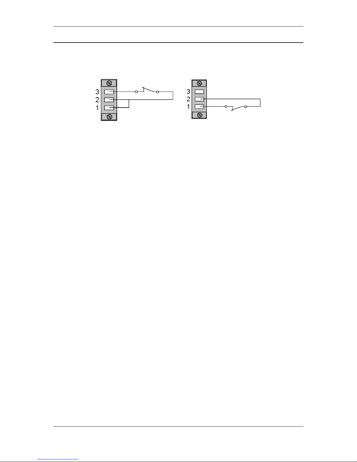
The triple output for connecting EPO/ROO circuits is located in the UPS unit's rear
panel - see Fig. 14.
ROO
EPO
Fig. 14: Remote power on/off circuits
In default configuration the UPS has a jumper connecting the outputs 1 and 2. These
outputs must be connected to ensure correct operation of the unit.
To use the emergency power off function remove the jumper and connect outputs 1
and 2 with a standard, zero voltage closed connector. If the connector is open the
UPS will switch off. To revert to normal operation close the connector and restart the
UPS, following the previously described procedure.
To use the remote power on/off function (ROO) connect the jumper in outputs 1 and
2 (by default, the UPS has the jumper installed) and then connect outputs 2 and 3
with a standard, zero voltage closed connector. The UPS switches off when the
connector is opened. Closing the connector restarts the UPS and powers on the
connected receivers.
Page 36
Instruction manual for POWERLINE RT 1-3 kVA UPS units
2016-07-13 12:09 Technical Support, tel.: +48 61 6500 400 www.ever.eu
36
COMMUNICATION WITH EXTERNAL
MANAGEMENT/CONTROL SYSTEMS
The UPS features RS232 and USB communication interfaces and also a
management card slot. These interfaces can be used to ensure direct communication
between the UPS and the work server, configure the UPS as a client in the network
with centralized monitoring through the UPS SNMP Manager installed in the slot, and
to transmit the unit's operating status to external systems.
RS232 PORT AND STATUS SIGNALING
The unit comes with an RS232 communication cable (null modem, 3-wire) for
monitoring and controlling the UPS with the supplied software.
CAUTION! The USP is also equipped with an RS232 cable (9-wire) for relaying the
status of the UPS to external devices. The cable looks just like the communication
cable, except for pin configuration. The cables are properly identified and should not
be mistaken. The status communication takes place through an optocoupler, an open
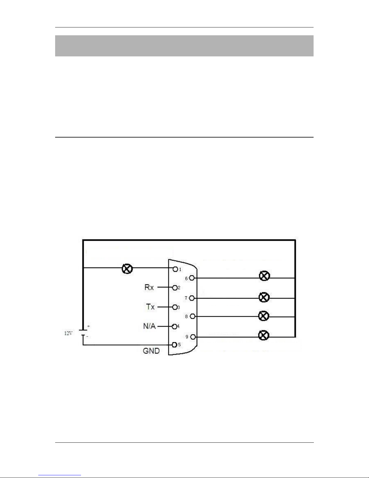
collector. The connector's configuration is shown in Fig. 15.
Fig. 15: Configuration of the status communication connector
Low battery charge level
Mains parameters out of range
Bypass mode
SUM alarm
Mains parameters corect
Page 37
Instruction manual for POWERLINE RT 1-3 kVA UPS units
37 www.ever.eu Pomoc Techniczna, tel.: +48 61 6500 400 2016-07-13 12:09
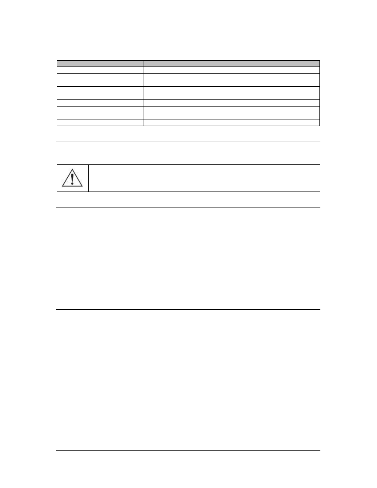
The pin configuration of the DB-9 connector is shown in table 3.
Table 3. Layout of pins and description of DB-9 connector:
Pin no.
Definition
4
Not connected
2
RXD (input)
3
TXD (output)
5
GND
1
Low battery charge
6
Mains parameters out of range
7
Bypass mode
8
SUM alarm
9
Mains parameters correct
USB port
The USB port is compatible with USB 1.1 standard.
CAUTION: RS232 and USB ports cannot be used simultaneously
SNMP/HTTP NETWORK MANAGEMENT CARD
Various cards can be connected to the interface slot. The connectors, designations
and codes placed in the socket will depend on the type of the used interface card.
The detailed description is attached to interface cards, available as accessories.
Available interface cards:
- SNMP network card for integrating the UPS in the network (optional),
- AS400 card (optional).
POWERSOFT
The UPS unit management/control using remote control systems (PC computer or
server-based) is performed using PowerSoft freeware.
PowerSoft freeware is designed to enable monitoring and configuring the UPS unit’s
parameters. It also features management and control functionalities which, when
combined with the UPS power supply unit, provide reliable and secure protection
against interruptions in power supply from the mains thus ensuring the continuity of
operation for unsupervised IT systems. PowerSoft also enables (from the level of the
central computer control unit) secure shutdown of other computers within a particular
LAN network.
Page 38

Instruction manual for POWERLINE RT 1-3 kVA UPS units
2016-07-13 12:09 Technical Support, tel.: +48 61 6500 400 www.ever.eu
38
The PowerSoft package is compatible with a wide range of operating systems, and
this versatility should help to meet the operating requirements of a majority of small
and medium enterprises (SMEs).
Current software and installation procedures are available for downloading at
www.ever.eu.
Page 39

Instruction manual for POWERLINE RT 1-3 kVA UPS units
39 www.ever.eu Pomoc Techniczna, tel.: +48 61 6500 400 2016-07-13 12:09
OPERATING REMARKS
CAUTION: The UPS is designed to work with IT equipment.
CLEANING
Do not use scrubbing powder and solvents to clean the UPS.
Do not let liquids get inside the UPS.
Make sure the openings in the UPS housing are not blocked. Use a vacuum cleaner
to remove dust from the openings.
The exterior of the UPS housing may be cleaned with a dry or slightly damp cloth.
STORAGE OF THE UPS
If the device is to be stored for a longer time in temperature of over 25ºC, the
batteries should be recharged for 5 hours, every 4 months. If the temperature in the
storage place is higher, it is recommended to reduce the interval to 2 months.
It is not necessary to unpack the UPS for recharging. Simply connect the UPS to the
mains through special openings in the packaging and recharge the batteries for
about 5 hours. Afterwards, write the date of recharging on the unit's packaging.
TESTING BATTERIES
Although the UPS does not require to be maintained by the user, the batteries should
be periodically checked.
Once a week the UPS will automatically test the batteries. If a problem is found, an
LED will light up to indicate it and an error message will be shown in the LCD display.
The frequency of testing can be altered with the panel or the software. Select the
TEST BATTERY EVERYDAY, EVERY WEEK, EVERY MONTH or DEACTIVATE in
the submenu AUTOMATIC BATTERY TEST in the SETTINGS menu.
Page 40
Instruction manual for POWERLINE RT 1-3 kVA UPS units
2016-07-13 12:09 Technical Support, tel.: +48 61 6500 400 www.ever.eu
40
BATTERY REPLACEMENT
CAUTION: receivers connected to the UPS will not be protected against
power failure during this procedure.
Replacing UPS internal batteries
The UPS does not need to be maintained by the user, but it is recommended to
perform maintenance according to IEEE standards with regard to recommended
practice for maintenance, testing, and replacement of service-free VRLA batteries for
stationary applications (IEEE Std 1188-1996). If the batteries become used up they
must be replaced technicians trained in battery operation.
Batteries are replaced in the service access area.
The service of batteries should be performed or supervised by personnel
experienced in the operation of batteries, observing the required precautions.
The same type and number of batteries or battery packs must be used when
replacing the batteries.
WARNING! Ensure suitable battery fire protection due to potential risk of
explosion.
WARNING! Never attempt to open the batteries. Always ensure suitable
battery protection against potential damage. Spilled electrolyte is harmful
to the eyes and skin, and could be toxic.
WARNING: There is risk of electric shock when handling the battery
pack.
WARNING: The battery is not isolated from power supply circuits.
Dangerous voltage may be present between the battery terminals and
the grounding point.
The following precautions should be taken when working with batteries:
Remove jewelry, watches, rings and other metal items.
Only use tools with insulated handles.
Page 41

Instruction manual for POWERLINE RT 1-3 kVA UPS units
41 www.ever.eu Pomoc Techniczna, tel.: +48 61 6500 400 2016-07-13 12:09
Wear rubber gloves and footwear.
Do not place tools or metal parts on the batteries.
Disconnect the source of power before connecting or disconnecting battery
terminals.
Typical lifespan of a battery is 3 to 5 years if the ambient temperature is 25ºC.
Regardless, the lifespan of a battery also depends on the frequency and duration of
power failures and periods of discharging the battery.
Once the battery's lifespan expires follow the procedure of replacing the battery.
The BATTERY TEST should be done periodically (6 to 12 months); it serves to verify
the general conditions of battery operation.
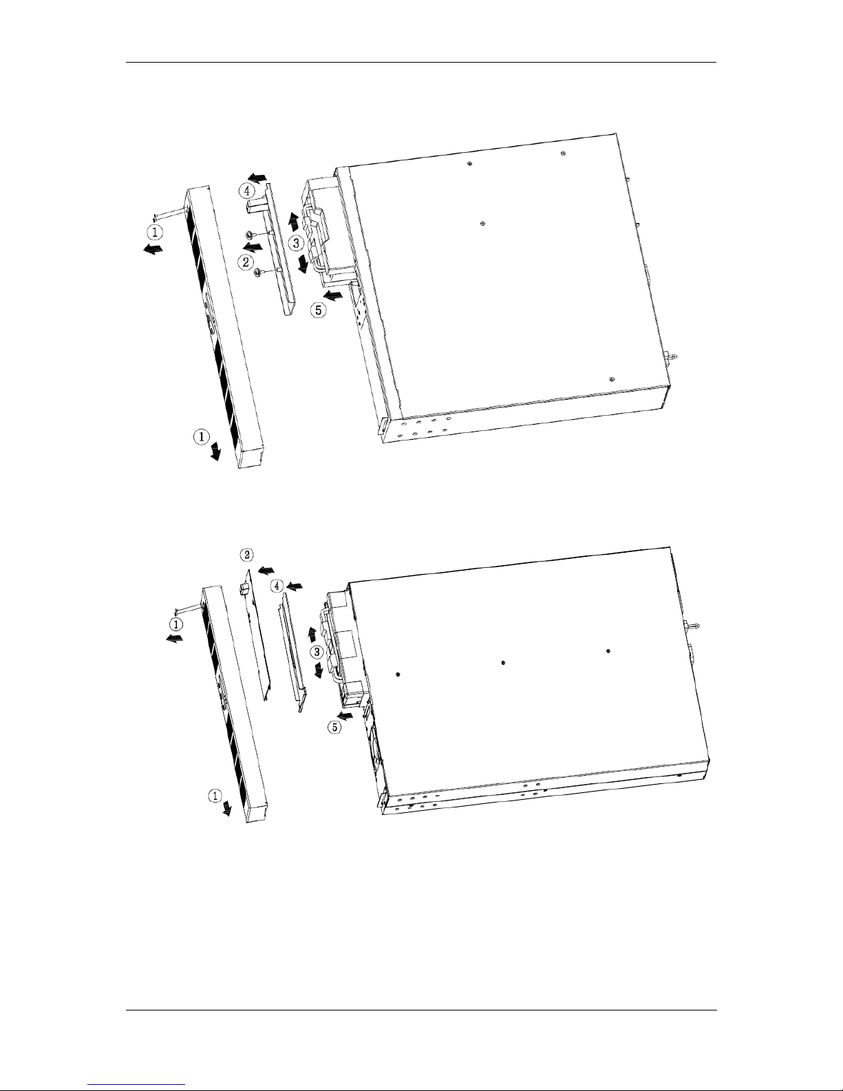
In order to replace the internal batteries, manually switch the UPS into bypass mode
(see "Bypass mode procedures") and follow the steps shown in Fig. 16 and Fig. 17:
Page 42
Instruction manual for POWERLINE RT 1-3 kVA UPS units
2016-07-13 12:09 Technical Support, tel.: +48 61 6500 400 www.ever.eu
42
Fig.16: POWERLINE RT 1000
Fig.17: POWERLINE RT 2000/3000
Page 43

Instruction manual for POWERLINE RT 1-3 kVA UPS units
43 www.ever.eu Pomoc Techniczna, tel.: +48 61 6500 400 2016-07-13 12:09
Battery disposal
The disposal / recycling of UPS units and/or batteries should be entrusted to a
specialist waste contractor with suitable license or authorization to engage in waste
disposal / recycling. Rechargeable batteries that have been used up are classified as
"dangerous toxic waste" and, according to legal regulations, must be disposed of or
recycled by an approved recycling facility.
The manufacturer’s service centre has all the equipment necessary to handle such
batteries in the way that fully complies with the relevant laws and regulations and
with the utmost care for the environment. Please contact our Customer Service
Department to arrange maintenance and / or replacement of the batteries.
After replacing the batteries, the approved waste disposal / recycling facility should
dispose of / recycle the used batteries.
The appropriate utilization of used electric and electronic equipment helps to
protect human health and the natural environment against the negative effects
caused by the presence of hazardous materials and components, and the
improper storage and processing of such equipment.
The Act of 29.07.2005 on the Disposal of Electric and Electronic Equipment,
Art. 22.1 points 1, 2.
The crossed out waste container symbol means that, in the
European Union, a used product should be handed over to a special
waste handling outlet. This requirement applies both to the UPS unit
itself and to all other accessories marked with this symbol. Such
products should not be disposed of together with unsorted municipal waste.
Page 44

Instruction manual for POWERLINE RT 1-3 kVA UPS units
2016-07-13 12:09 Technical Support, tel.: +48 61 6500 400 www.ever.eu
44
TECHNICAL PARAMETERS
Table 4. POWERLINE RT technical parameters.
PARAMETERS \ TYPE
POWERLINE RT
POWERLINE RT 1000
POWERLINE RT 2000
POWERLINE RT 3000
Index
T/PWRLRT-111K00/00
T/PWRLRT-112K00/00
T/PWRLRT-113K00/00
Output power (apparent / active) 1)
1000 VA / 800 W
2000 VA / 1600 W
3000 VA / 2400 W
GENERAL AND ENVIRONMENTAL DATA
Topology
VFI (on-line, VFI-SS-111)
Number of voltage phases (input / output)
1 / 1
Housing type 2)
Rack / Tower
Max. efficiency (for VFI)
86 %
88 %
90 %
Efficiency (for ECO)
˃ 93 %
Operating temperature 3)
0 ÷ +40 °C
Storage temperature
-15 ÷ +40 °C with batteries
-25 ÷ +50 °C w/o batteries
Relative humidity during operation
< 95% (no condensation)
Relative humidity during storage
< 95% (no condensation)
Elevation 4)
up to 3000 m
Protection class
IP20
Working environment
Office / industrial rooms with low level of pollution
Cooling
Forced, with internal fans
Cooling air temperature
< 25°C
Radiated heat for nominal operating conditions
< 450 BTU / h
< 750 BTU / h
< 1000 BTU / h
INPUT
Rated voltage (effective value)
230 V AC
Input voltage range (effective values) and
tolerance
120 ÷ 275 V AC ± 2%
140 ÷ 275 V AC ± 2%
Rated current
6 A
12 A
16 A
Rated frequency, input voltage
50 / 60 Hz
Frequency range and tolerance
40 / 70 Hz (input-output synchronization range: ± 5 % )
PF power factor
≥0.99
Total harmonic distortion, input current (THDi)
< 8%
OUTPUT
Rated voltage (effective value)
230 V AC
Input voltage range (effective values)
and tolerance - mains operation 5)
200 V AC / 208 V AC / 220 V AC / 230 V AC / 240 V AC ± 2 %
(The output voltage is adjusted from the LCD panel. The default value is 230 V AC)
Input voltage range (effective values)
and tolerance - back-up operation 5)
200 V AC / 208 V AC / 220 V AC / 230 V AC / 240 V AC ± 2 %
(The output voltage is adjusted from the LCD panel. The default value is 230 V
AC.)
Output voltage waveform (battery / mains-based
operation)
Sine / Sine
Output voltage rated frequency
50 / 60 Hz
Frequency range (tolerance) - mains-based
operation
50 / 60 Hz ± 0,5%
(same as in the input or selected in the frequency conversion mode)
Frequency range (tolerance) - battery operation
50 Hz ± 0,5%
Static voltage regulation
± 1%
Total harmonic distortion, output current (THDu)
≤ 4% (linear)
≤ 6% (non-linear)
CF peak ratio
3:1
Switching time to battery mode
0 ms
Switching time to return to the mains-based
operation
0 ms
Overload capacity
6)
< 110% - warning
111% ÷ 135% - 12 s (switching to bypass mode)
> 135% - 1,5 s (UPS shuts dwon)
Page 45

Instruction manual for POWERLINE RT 1-3 kVA UPS units
45 www.ever.eu Pomoc Techniczna, tel.: +48 61 6500 400 2016-07-13 12:09
PARAMETERS \ TYPE
POWERLINE RT
POWERLINE RT 1000
POWERLINE RT 2000
POWERLINE RT 3000
BATTERIES AND BACKUP TIMES
Internal batteries
12 V / 9 Ah VRLA
12 V / 9 Ah VRLA
Total number of internal batteries
1 x 3
1 x 6
Maximum permissible combined capacity of
internal battery pack
9 Ah
External battery packs
Yes
Maximum number of battery packs
4
Backup time using internal battery pack (100% /
80% / 50% of Pmax)
8 / 12 /20 min.
8 / 12 / 20 min.
3 / 6 / 12 min.
Backup time using internal batteries + battery
pack (100% / 80% / 50% of Pmax)
26 / 37 /78 min.
26 / 37 / 78 min.
20 / 28 / 41 min.
Rated voltage for the DC circuit
36 V DC
72 V DC
Maximum charging time for UPS internal
batteries - after batteries have been 80%
discharged
≤ 4 h
Charging current, maximum
1.2 A
MECHANICAL PARAMETERS
Dimensions (height. x width x depth)
86 (2U) x 438 x 482 mm
86 (2U) x 438 x 658 mm
Weight
7)
18.5 kg
30.5 kg
31 kg
Weight for transporting (gross)
7)
22 kg
35 kg
36 kg
Dimensions for transporting (height. x width x
depth)
245 x 530 x 625 mm
230 x 585 x 880 mm
Position in transit
Horizontal
PROTECTIONS AND SAFEGUARDS
Input protection
Short circuit protection -
Automatic fuse
10 A / 250V AC
Short circuit protection -
Automatic fuse
12 A / 250V AC
Short circuit protection -
Automatic fuse
16 A / 250V AC
Against overvoltage (Anti-surge)
Output protection
Inverter-based operation – electronic short-circuit protection and overload
protection
FEATURES AND ADDITIONAL FUNCTIONS
UPS power supply connection
1 x IEC 320 C14 (10 A)
1 x IEC 320 C20 (16 A)
Output connections (socket type and quantity)
3 x IEC 320 C13 (10A) controlled (2 groups)
3 x IEC 320 C13 (10A) non-controlled
3 x IEC 320 C13 (10A)
controlled (2 groups)
3 x IEC 320 C13 (10A)
non-controlled
1 x IEC 320 C19 (16A)
EPO / ROO
Yes (NC) / Yes
Signaling
Acoustic and visual; LCD display; LEDs
Communication interface
RS232, USB, Port RJ11 – detection of battery packs,
network management card SNMP / HTTP – optional,
AS 400 card with volt-free contacts - optional
Monitoring and management software
PowerSoft Professional
GREENPOWER operating threshold 8)
< 45 W
STANDARDS APPLIED
Declarations
CE
Standards
PN-EN 62040-1:2009, PN-EN 62040-2:2008
Caution: The manufacturer reserves the right to change the above listed parameters without notice.
ADDITIONAL NOTES:
1)
To ensure normal operation of the UPS unit, the load at its output should not exceed 80% of the value given in the chart. A
power reserve is necessary to maintain continuity of operation of connected appliances in case of momentary surges of load
current.
2)
The Rack Kit is optional.
3)
With internal batteries 5 ÷ 35°C. Constant exposure of the device to environment temperature over +25°C results in reducing
battery life.
4)
Maximum allowed load the UPS unit will decrease as the altitude above the sea level increases over the specified limit.
5)
Can be configured by software and LCD display. The output power is reduced by 20% for rated output voltage of 200 V. The
output power is reduced by 10% or rated output voltage 208 V.
6)
With prolonged operation with recommended load.
7)
Weight for the typical battery.
8)
In battery mode with no load or load less than threshold value, UPS turn off automatically after 5 minutes.
Page 46

Instruction manual for POWERLINE RT 1-3 kVA UPS units
2016-07-13 12:09 Technical Support, tel.: +48 61 6500 400 www.ever.eu
46
Table 5. Technical parameters of battery packs for POWERLINE RT
PARAMETER/MODEL
BATTERY MODULE
POWERLINE RT 1000
BATTERY MODULE
POWERLINE RT 2000/3000
Casing
Rack / Tower
(The Rack Kit is optional)
List of batteries
2 x 3 x 9 Ah
2 x 6 x 9 Ah
Protection devices
Fuse 70 A / 80 V DC
Fuse 70 A / 80 V DC
MECHANICAL PARAMETERS
Dimensions W x H x D
438 x 86 (2U) x 438 mm
438 x 86 (2U) x 657 mm
Rack cabinet depth
≤ 800 mm
Weight
32 kg
52 kg
ENVIRONMENT
Operating temperature 1)
0 ÷ 40 ºC
Storage temperature
-15 ÷ 40 ºC
Elevation 2)
0 - 3000 m
Relative humidity during operation
< 95% (no condensation)
Relative humidity during storage
< 95% (no condensation)
Caution: The manufacturer reserves the right to change the above listed parameters without notice.
Notes:
1)
Constant exposure of the device to environment temperature over +25°C results in reducing battery life.
2)
Maximum allowed load the UPS unit will decrease as the altitude above the sea level increases over the specified limit.
Page 47

Instruction manual for POWERLINE RT 1-3 kVA UPS units
47 www.ever.eu Pomoc Techniczna, tel.: +48 61 6500 400 2016-07-13 12:09
TROUBLE SHOOTING
If problems occur, despite the high reliability of the device, please check the following
items before contacting the customer service department:
a) Is there correct voltage supply in the UPS input?
b) Is the input fuse in good working condition? Did the battery pack fuses trip
automatically?
Table 6. Typical statuses and alarms, their causes and recommended activities.
Problems
Possible cause
Corrective measures
No recommendation
No alarm sound
(UPS off)
Mains power switched off
Switch on the mains power switch
No mains power voltage
Order mains power inspection from a qualified
electrician
Burnt input fuse or circuit
protection automatically switched
off
Replace with a fuse of the same type, or switch
on circuit protection. If the problem persists,
contact the appropriate customer service
representative
Overload message on the LCD display
Receiver connected
Overload error: UPS is overloaded
Check the value of the current supplied by the
receivers. Reduce the number of the connected
receivers. Restart the UPS
Battery error message is displayed on the
LCD.
Battery error detected during the
automatic battery test
Inspect if the battery connector is properly
connected.
Replace the battery pack
Battery error LED flashes/long sound signal
approx. every hour
Battery lifespan is ending, battery
duty time is reduced
Switch off the alarm by pressing the ESC
button for 3 seconds
Replace the battery pack
An internal error message is displayed on
the LCD.
UPS error
Contact the customer service representative
Overheat error message is displayed on
the LCD.
Overheating
Reduce the ambient temperature
Autonomous power supply time shorter
than in the specifications
Battery pack safeguard is OFF
Switch the battery pack safeguard to ON
Batteries not fully charged
Recharge the batteries and test the working
time in backup mode. If the problem persists,
contact the customer service representative.
Batteries are damaged
Contact the customer service representative
The charger is damaged
Contact the customer service representative
No communication between the UPS
and the PC
Incorrect serial connection cable
Check if a proper cable is used
The PC's interface is being used by
another process or is damaged
Check if other software / service has access to
the PC's interface; try selecting another serial
interface
Interferences in the data cable
Reinstall / change the position of the cable
Page 48

Instruction manual for POWERLINE RT 1-3 kVA UPS units
2016-07-13 12:09 Technical Support, tel.: +48 61 6500 400 www.ever.eu
48
LEGAL REGULATIONS AND WARRANTY
DECLARATION OF CONFORMITY
The UPS structure conforms to the appropriate subject matter standards.
WARRANTY
A separate document attached to the product constitutes the warranty. The
document must meet all formal requirements (e.g. the fields: serial number,
model/type, date of sale, and dealer stamp must be filled out).
The manufacturer has made every effort to ensure that the offered products are free
of defects in materials and workmanship. The liability of the manufacturer under this
warranty is limited to the repair or replacement of products containing such defects.
The method to remove such defects shall be determined by the manufacturer. The
guarantee shall not cover appliances with mechanical damages that were improperly
maintained or used, or that were modified in any way by the user.
EVER Sp. z o.o. does not provide any guarantees or warranties, including the
guarantees of fitness for sale or for any specific purpose, other than the provisions
set out in the warranty card.
EVER Sp. z o.o. shall not be liable for any direct, indirect, extraordinary, coincidental,
or consequential losses resulting from the use of the UPS unit, even if the user has
not been notified of the possibility of such losses being incurred. The company shall
not be held liable for any costs, such as the loss of profits or earnings, loss of
equipment or equipment usage, software, data, costs of replacement products,
claims of third parties, or for any other costs whatsoever.
Information on warranty and post-warranty repairs as well as other maintenance
services, as well as this instruction in English, Czech and Slovak can be obtained on
our website at www.ever.eu.
 Loading...