

Event Lighting PRO PAR19x15, PRO PAR19x15O User Manual
PRO PAR
Model No. PAR19x15, PAR19x15O
USER MANUAL
For safety, please read this user manual carefully before initial use.
Event Lighting reserves the right to revise the manual at any time. Information and specifications within this
manual are subject to change without notice. Event Lighting assumes no liability or responsibility for any
errors or omissions. Please consult Event Lighting for any clarification or information regarding this item.
www.event-lighting.com.au
Ver 3.0

Safety Instructions
- Power input & power Linking
Product Installation
- Fuse replacement
Diagrams
- Lux chart
- Dimensions
- Fade Mode Chart
Control Board Operation
www.event-lighting.com.au
CONTENTS
- DMX address setting
- DMX modes setting
- Dimmer Speed Setting
- Static colour setting
- Manual colour setting
- Auto run and sound active setting
- Master/slave setting
DMX chart
Technical specifications
Warranty
1

www.event-lighting.com.au
Safety Instructions
WARNING
• Do not open this device, there is no user-serviceable parts inside. Risk of electric shock.
• Do not look at the light source when the device is on.
• CAUTION: This unit's housing may be hot during and after operation.
• Install this device in a location with adequate ventilation, at least 20 inch (50 cm) from adjacent surfaces.
• Do not leave any flammable material within 50 cm of this unit while operating or connected to power.
• Use a safety chain when mounting this device overhead.
• Do not operate this device outdoors or in any location where dust, excessive heat, water, or humidity may affect it.
• Do not operate this device if the housing, lenses, or cables appear damaged.
• Do not connect this device to a dimmer or rheostat.
• ONLY connect this device to a grounded and protected circuit.
• ONLY use the hanging bracket to carry this device.
• In case of a serious operating problem, stop using immediately.
• The maximum ambient temperature is 104° F (40° C). Do not operate this device at higher temperatures.
Power Input & Power Linking
This device has an auto-switching power supply work with input voltage range of 100~240 VAC, 50/60 Hz.
Link up to the maximum 8A. DO NOT exceed this number.
The maximum number of units that can be power linked is 4 units at 110V and 8 units at 240V.
Product Installation
This device can be mounted in many orientations provided each individual device is secured by the use of correct
mounting bracket.
Use a safety chain when mounting this device overhead.
Fuse Replacement
If the fine-wire fuse of the device fuses, only replace the fuse by a fuse of same type and rating.
Before replacing the fuse, unplug mains lead.
Procedure:
Step 1: Unscrew the fuse holder on the rear panel with a fitting screwdriver from the housing (anticlockwise).
Step 2: Remove the old fuse from the fuse holder.
Step 3: Install the new fuse in the fuse holder.
Step 4: Replace the fuse holder in the housing and fix it.
2
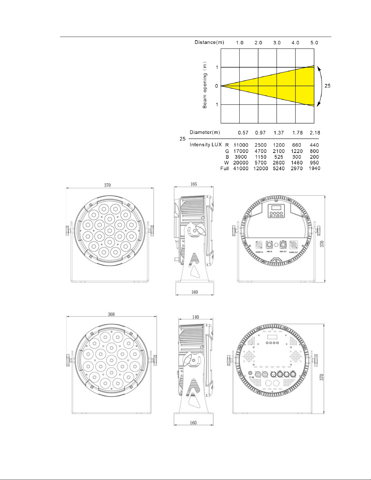
Lux Chart
Dimensions
www.event-lighting.com.au
3
 Loading...