

Page 1
615
requirements in your area.
Installation & Operations Manual
Element-MF
Please read this entire manual before installation and use of this Multi-Fuel burning
room heater. Failure to follow these instructions could result in property damage,
bodily injury or even death."
Contact local building or fire officials about restrictions and installation inspection
Save these Instructions
Element-MF Installation and Operations Manual
Page 1
Page 2

TABLE OF CONTENTS
General Information ....................................................................................................................... 4
Installation Check List ............................................................................................................... 5, 6
Element-MF Layout Diagram ..................................................................................................... 7, 8
Element-MF Dimension ................................................................................................................. 9
Approved Installations .....................................................................................................................9
Venting - Approved Materials .......................................................................................................10
Venting Size Guidelines .................................................................................................. 10
Venting-Typical PL Vent Components ............................................................................11
Venting - Determining Materials ................................................................................... 12
Venting - Termination Requirements ......................................................................... 13-14
Venting: Termination Clearance Requirements ............................................................. 15
Venting – Into an existing Chimney .................................................................................16
Venting – Hearth Mount ...................................................................................................17
Floor Protection ........................................................................................................................... 18
Minimum Clearances ............................................................................................................. 19-20
Outside Combustion Air ............................................................................................................... 21
Mobile Home Installation ..............................................................................................................22
Element-MF Operation ...............................................................................................................23
Preventing Chimney Fires...........................................................................................................23
Approved Fuels ...........................................................................................................................23
Corn, Wheat, Rye, Cherry Pits & Distiller’s Grain ............................................... 23-25
Installation Check .................................................................................................................25, 26
Element-MF Installation and Operations Manual
Page 2
Page 3

Control Board Features .........................................................................................................26, 27
Pre-Lighting Instructions ...................................................................................................... 27-28
Lighting Instructions ...................................................................................................................29
Shutting Off the Insert ................................................................................................................30
Importance of Proper Draft .........................................................................................................30
Initial Damper Settings ................................................................................................30
Adjusting the Damper ............................................................................................31, 32
Flame Pattern Characteristics ......................................................................................32
Use of a Thermostat ............................................................................................................ 32, 34
Diagnostic Features & Safety Sensors .................................................................................. 34-36
Element-MF Maintenance .............................................................................................................37
Clinker/Ash Removal (Multi-Fuel pot) ..........................................................................37
Daily Maintenance (Multi-Fuel Pot) ......................................................................... 37-40
Periodic Maintenance................................................................................................ 41-43
Yearly Maintenance ..................................................................................................43, 44
Safe Operation ...............................................................................................................................44
Wiring Schematic...........................................................................................................................45
Troubleshooting & Frequently Asked Questions ............................................................... 46-49
Parts Breakdown ...................................................................................................................... 50-57
Warranty ........................................................................................................................................58
Element-MF Info & Notes .............................................................................................................59
Element-MF Installation and Operations Manual
Page 3
Page 4

Save This Installation & Operations Manual
GENERAL INFORMATION SAFETY PRECAUTIONS
SAFETY NOTICE: The ELEMENT-MF must be properly installed in order to prevent the
possibility of a house fire! These installation instructions must be strictly observed! The
Maintenance schedule must be followed as described in this manual. Failure to follow
instructions may result in property damage, bodily injury or even death.
The Element-MF’s exhaust system works with negative combustion chamber pressure and a
slightly positive chimney pressure. Therefore, it is imperative that the air intake and exhaust
system be airtight and installed correctly. Do not install a flue damper in the exhaust vent of this
unit.
Do not connect this unit to a chimney flue serving another appliance.
BUILDING PERMIT
Contact the local building officials to obtain a permit and information on any local installation
restrictions and inspection requirements.
DEFINITION OF “STOVE”
The word “Stove” as used in this manual to describe the Element-MF is interpreted to mean a
Multi-Fuel Stove approved for Corn, Wheat, Rye, Cherry Pits and Distiller’s Grain. This stove is
not intended as the sole source of heat.
EMISSIONS TESTING
The Element-MF is a “Non-Affected Facility” and was not tested to comply with U.S.
ENVIRONMENTAL PROTECTION AGENCY 2020 particulate emission standards using pellet
fuel.
The Element-P was certified to the 2020 Phase of ASTM E2779-2010. Heat Output: 8874
BTU/hr – 25406 BTU/hr, Efficiency: 64.7% using the higher Heat Value of the Fuel. Emission
Rate .660 gr/h
SAFETY TESTING
The Element-MF has been independently tested and listed by Warnock Hersey Laboratories in
accordance with the proposed ASTM E 1509-2004 Standards and the applicable portions of UL
1482 and ULC S627/B366.2, and Oregon Administrative Rules 814-23-901 through 814-23909, stating requirements for installation the Element-MF and for mobile home installations. The
safety-listing label is located on the top of the hopper. Please refer to label for pertinent
information.
DISCLAIMER OF WARRANTY
Since Even Temp Company has no control over the installation of the Element-MF, Even Temp
Company grants no warranty, implied or stated, for the installation of the Element-MF and
assumes no responsibility for any special, incidental or consequential damages.
MANUFACTURED FOR:
Even Temp Inc., Hwy 34, Waco, NE, 68467, Phone: 1-402-728-5255
Element-MF Installation and Operations Manual
Page 4
Page 5

INSTALLATION CHECK LIST
- FOR USE IN THE U.S. AND CANADA
- MOBILE HOME APPROVED
- CHECK WITH LOCAL AUTHORITIES AND OBTAIN NEEDED PERMITS. OBTAIN
FINAL INSPECTION FROM LOCAL BUILDING OFFICIALS.
- WE RECOMMEND INSTALLATION BY A QUALIFIED PROFESSIONAL OR
DEALER.
- ADHERE TO ALL CLEARANCES SPECIFIED BY THE MANUFACTURER OF THE
VENTING SYSTEM USED.
-
ADHERE TO ALL CLEARANCES SPECIFIED IN THE INSTALLATION
INSTRUCTIONS OF THIS STOVE.
- THIS STOVE USES A POSITIVE PRESSURE VENTING SYSTEM. DO NOT
INSTALL A FLUE DAMPER IN THE EXHAUST SYSTEM OF UNIT.
- DO NOT CONNECT THIS STOVE TO A CHIMNEY SYSTEM THAT IS
CONNECTED TO ANOTHER APPLIANCE.
- DO NOT INSTALL THIS UNIT IN A SLEEPING ROOM.
- INSTALL A SMOKE DETECTOR IN PROXIMITY OF THE STOVE.
- INSTALL A CARBON MONOXIDE DETECTOR IN PROXIMITY OF THE STOVE
ATTENTION
- CONDENSATION
:
When planning the installation of your Stove, keep in mind that
condensation is detrimental to exhaust systems. Install the Stove with a minimum of the
vent system exposed to the cold temperatures outside the envelope of the house.
- BATTERY BACKUP: St Croix does not offer battery backups. They are available online
if you decide to use one. Battery backup systems are useful if the Stove is installed using
horizontal venting only. This prevents any smoke from entering your home in the event of a
power failure.
- OPTIONAL EXHAUST FAN RELAY KIT: With optional relay kit 80P54232 installed in
the stove and connected to an inexpensive UPS battery backup (not part of the kit) you will
have maximum protection against smoke leaking out of the stove in the event of a power
failure. This is considered the best installation when venting horizontally. Contact your
dealer for more information.
1. All joints of PL vent and single wall stainless steel pipe should be fastened by at least 3
screws and correctly installed. (Follow vent manufacturer’s instructions). Seal all joints with
high temperature silicone to create an airtight seal.
Element-MF Installation and Operations Manual
Page 5
Page 6

2. A certain amount of carbon monoxide may be produced within the Stove as a by-product of
combustion. All exhaust vent connections must be sealed with RTV silicone to assure a gas tight
seal. Any leaks into a confined area caused by faulty installation or improper operation of
the Stove could produce dizziness, nausea and in extreme cases, death. The CO
concentration in the flue gas during the testing of the Element-P was 11.31 g/hr. The ElementMF is a “Non-Affected Facility” and was not tested.
3. WARNING: The high temperature paint on this Stove may take several hours of burning at a
high fuel setting to cure fully. During this time, an odor that is not harmful may be evident.
When odors are present, the area around the Stove should be well ventilated.
4. Caution: The high temperature paint can be easily scratched prior to burning the Stove.
5. Have your dealer demonstrate all the operational and maintenance steps necessary for proper
use of the Stove. Sign and return the warranty card to the address listed on the back page.
6. Some odors may be given off during the first few hours of burning during initial break-in.
These odors are normal and not harmful. However, ventilating the room until the odors disappear
is recommended.
7. The Stove will become HOT while in operation. Keep clothing and furniture away from all hot
surfaces.
8. To avoid the possibility of smoke and/or sparks entering the room always keep firebox and ash
pan doors closed whenever the Stove is operating. Smoke detectors, installed in the same general
area as the Stove, may be activated if the Stove door is left open and smoke is allowed to enter
the area.
9. Under certain circumstances an outside source of combustion air may be needed and is
required on all mobile home installations. Use only approved parts. When using outside air for
combustion, check that the outside air inlet is connected to draw fresh air from outside the
building. If room air is used to supply combustion air, room air starvation (not enough make-up
air), operation of exhaust fans and icing of air vents can adversely affect proper Stove operation.
This Multi-Fuel heater has a manufacturer-set minimum low burn rate that must not be altered. It
is against federal regulations to alter this setting or otherwise operate this Multi-Fuel heater in a
manner inconsistent with operating instructions in this manual.
CAUTION: FAILURE TO FOLLOW THE INSTRUCTIONS IN THE INSTALLATIONS
MANUAL MAY RESULT IN A HOUSE FIRE, PROPERTY DAMAGE, BODILY
INJURY, OR EVEN DEATH. PLEASE FOLLOW INSTALLATION AND
MAINTENANCE INSTRUCTIONS.
CAUTION: NEVER ADD FIRE STARTER TO A HOT STOVE.
CAUTION - Hot Surfaces
- Keep Children away.
- Do not touch during Operation.
Element-MF Installation and Operations Manual
Page 6
Page 7
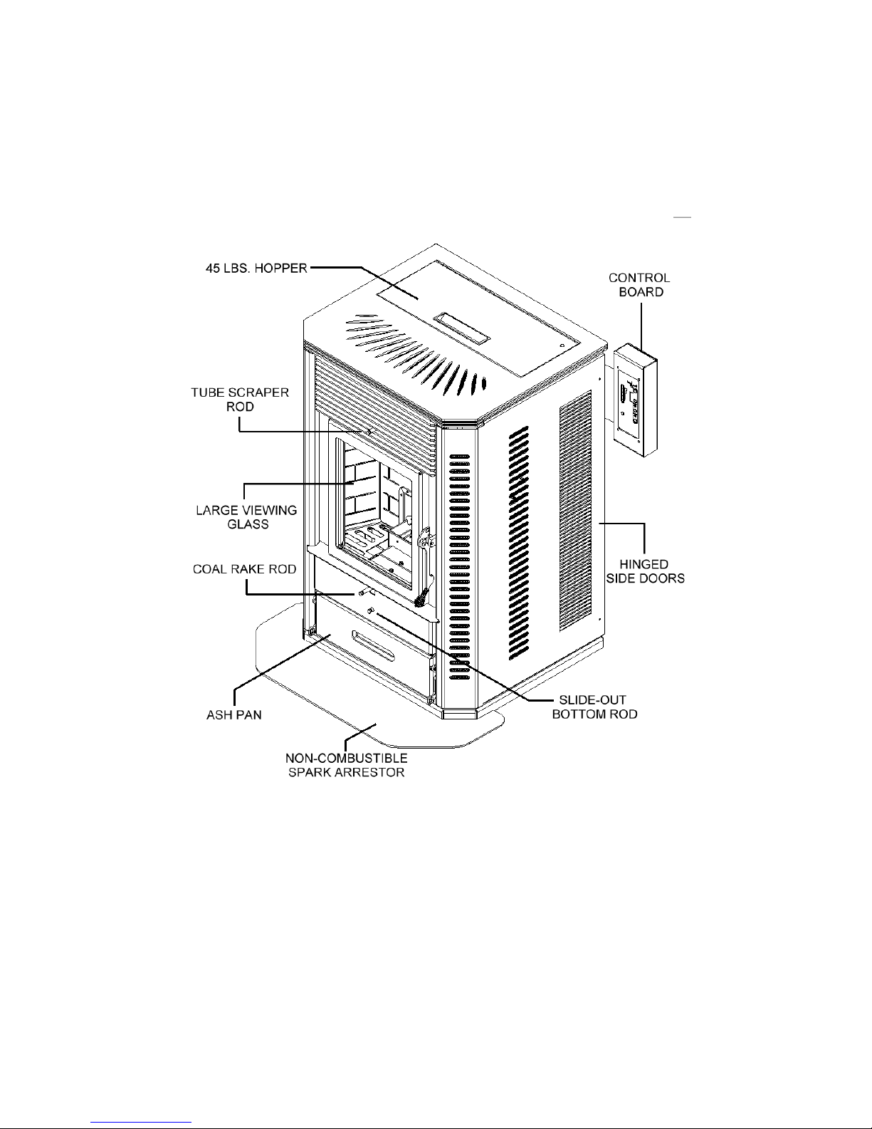
Element-MF
Stove Layout
Figure 1
There are two burn systems used in Element Series of stoves. These systems are
interchangeable in the stove body. This Manual covers the ELEMENT-MF, which uses the
Multi-Fuel Burn System
The Multi-Fuel Burn System is the St. Croix Patented “Clinker Removal System”. This
burn pot allows the clinker to be removed without losing the fire in the pot. This eliminates
the need of having to re-light the after removing the clinker. This burn system does not have
Self-Ignition. It is approved for Corn, Wheat, Rye, Cherry Pits & Distillers Grain.
Element-MF Installation and Operations Manual
Page 7
Page 8
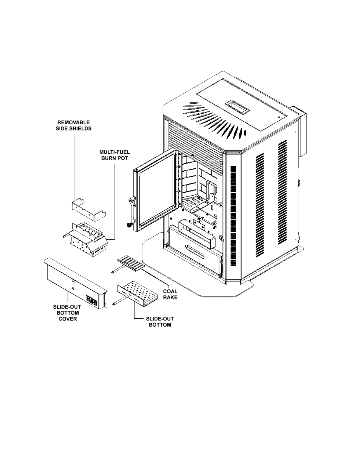
Figure 2
The Multi-Fuel Burn System is approved for Corn, Wheat, Rye, Cherry Pits and Distillers
Grain. Wood pellets are no longer approved for use (except as starter pellets) in ElementMF’s built after the 2015 NSPS.
Element-MF Installation and Operations Manual
Page 8
Page 9
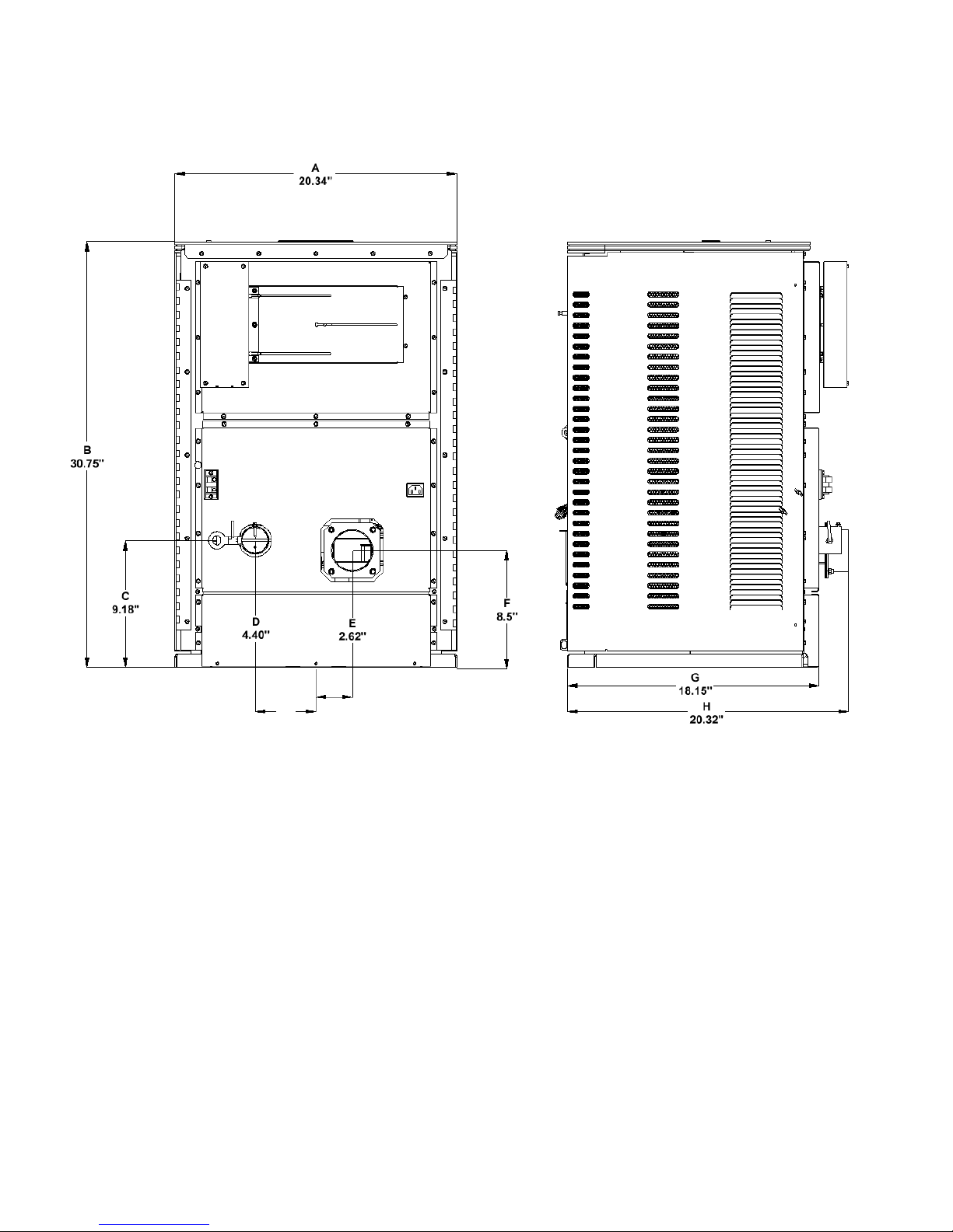
STOVE DIMENSIONS
Figure 3
A - Width of Stove E - Center of stove to center of exhaust
B – Height of Stove F - Center of exhaust from Base of Stove
C – Center of Air Intake from Base of Stove G – Front of Stove to Back of Stove
D - Center of Stove to Center of Air Intake H – Front of Stove to end of Exhaust Pipe
The Element-MF is approved for CONVENTIONAL and MOBILE HOME installations as a
FREESTANDING stove. The stove may also be installed on the Hearth in front of a Fireplace
and vented through the chimney of the fireplace.
Element-MF Installation and Operations Manual
Approved Installations
Page 9
Page 10
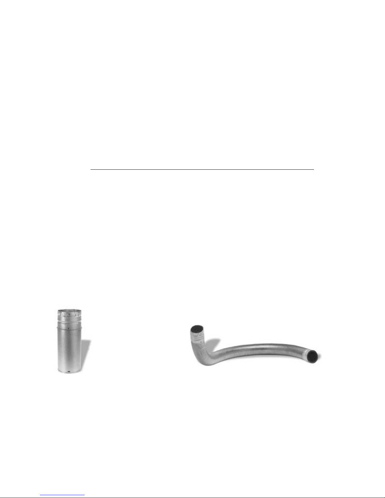
VENTING: APPROVED MATERIALS
The Element-MF requires a venting system approved for pellet or corn venting by a certified
testing lab. Approved pellet or corn venting materials are: 1) PL vent, a double wall vent with a
stainless steel liner; and 2) Single wall rigid or flexible stainless steel pipe. PL Vent and Single
wall vent is available through manufacturers such as: ICC Pellet Vent, Energy Vent LTD, James
A. Ryder, Simpson Dura Vent and Selkirk Metalbestos and is carried by many local dealers. In
this manual approved venting will be referred to a “PL vent” or “Single wall vent”. All single
wall vent adaptors must be stainless steel.
NOTE: TYPE “B” GAS VENT MUST NOT BE USED IN THE INSTALLATION OF THIS MULTIFUEL STOVE.
Venting size Guidelines
Type of Installation: Size:______________
A. Less than 10’ horizontal: 3” Acceptable
B. 10’ to 12’ horizontal: 3” or 4” Acceptable
C. Over 12’ horizontal: 4” Required
Horizontal installation over 12’ is NOT RECOMMENDED
D. Less than 15’ vertical: 3” Acceptable
E. Over 15’ vertical: 4” Required
F. Above 4000’ elevation: 3” or 4” Acceptable
Note: Four (4) inch vent may be used in all installations. If in doubt, use 4” vent.
Examples of venting system components follow:
High temperature ceramic roping reduces potential fly ash escaping through joints.
Stainless steel inner liners resist corrosive flue gas damage to the system.
Flex pipe should be stainless steel, 4 ply construction with a total thickness of approximately .07
inches.
Element-MF Installation and Operations Manual
Page 10
Page 11
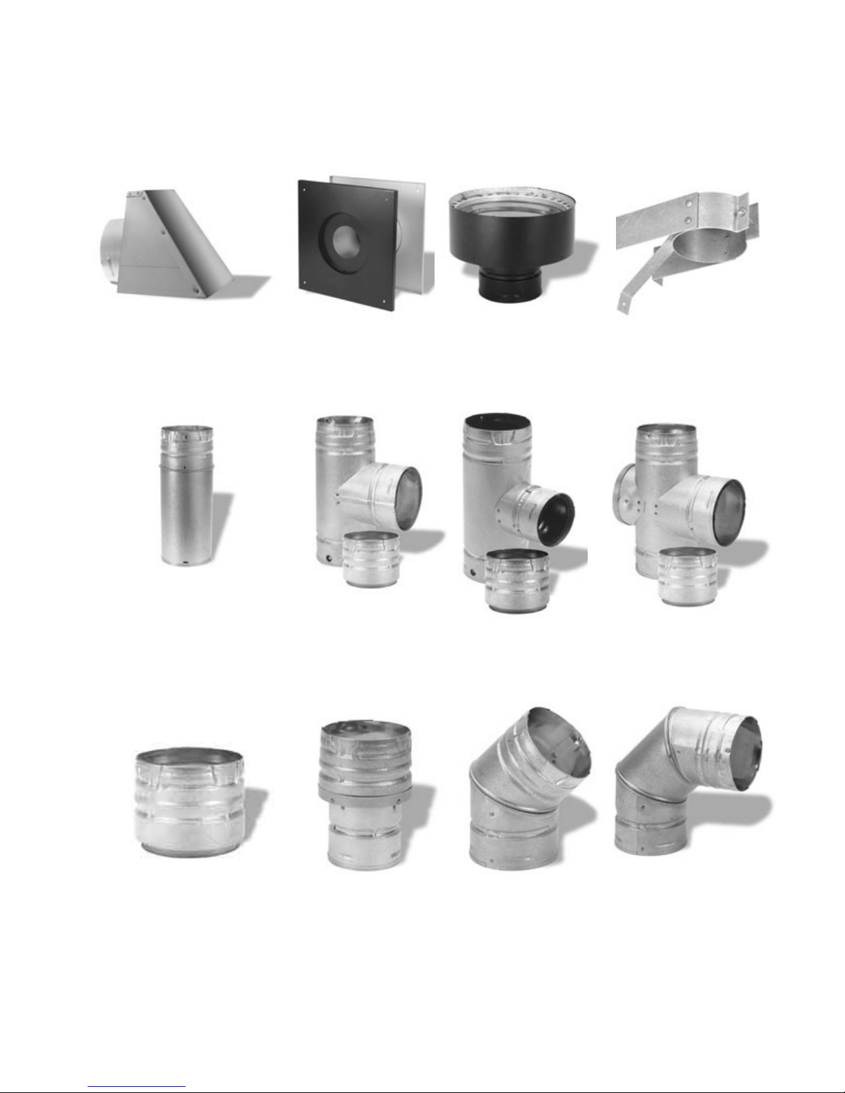
TYPICAL PL VENT COMPONENTS
RAIN CAP
VERTICAL OR WALL THIMBLE CHIMNEY SUPPORT BRACKET
HORIZONTAL ADAPTER
ADJUSTABLE LENGTH SINGLE TEE SINGLE REDUCTION DOUBLE TEE
PIPE w/TEE CAP TEE w/TEE CAP w/TEE CAP
PIPE ADAPTER INCREASER 450 ELBOW 900 ELBOW
Element-MF Installation and Operations Manual
Page 11
Page 12

VENTING: DETERMINING MATERIALS
TYPE OF MATERIALS:
1. PL Vent / Corn Vent must be used.
2. All Joints in the venting installation must be fastened together using three screws. All joints of
the venting system must be sealed with High Temp Silicone to make a gas tight fit.
3. Exception: Single wall stainless steel may be used inside an existing chimney. (No
clearances to combustibles are needed on single wall stainless steel adaptors, rigid or flex pipe
installed within a chimney.)
4. A clean-out “tee” (PL Vent or “Quick-Connect Exhaust”) must be installed directly to the
Stove and at the bottom of each vertical run of the exhaust system. These tees are to assist in
periodically cleaning the pipe. Single or double clean-out tees may be used. The exhaust system
must be installed so the entire system can be cleaned without disassembly.
NOTE: ADHERE TO THE PL VENT CLEARANCES TO COMBUSTIBLES AS REQUIRED.
STRICTLY OBSERVE THE PL VENT MANUFACTURER’S SAFETY SPECIFICATIONS.
QUANTITY OF MATERIALS:
1. It is recommended that the vent system be installed with a minimum of three feet (3’) of
vertical rise above the exhaust port on the back of the Element-MF.
FAILURE TO PROVIDE THE NATURAL DRAFT THAT RESULTS FROM A VERTICAL
RISE MAY RESULT IN SMOKE BEING RELEASED INTO THE HOUSE WHEN
ELECTRICITY TO THE UNIT IS INTERRUPTED WHILE BURNING OR SMOLDERING
FUEL REMAINS IN THE BURN GRATE. (See “Battery Backup” on page 5)
2. It is not recommended to run vertical venting outside the heated environment where the
Element-MF is installed. Running a venting system in a cold environment may cause the flue
temperatures to cool down too much for adequate drafting.
Additional vertical exhaust venting should be provided when using:
a. More than one (1) elbow or tee; and/or
b. Horizontal runs of over three (3) feet. (Horizontal runs over 10 feet not recommended)
3. For a venting system ending in a horizontal run, the exhaust pipe must be terminated by a
listed end cap or a PL vent elbow (45 or 90 degrees). Note: End caps or elbows must vent
exhaust gases away from the building.
4. For termination above the building roofline a rain cap is required.
5. The exhaust pipe on all Element-MF’s is 3” O.D. to accommodate a pipe adaptor.
Element-MF Installation and Operations Manual
Page 12
Page 13
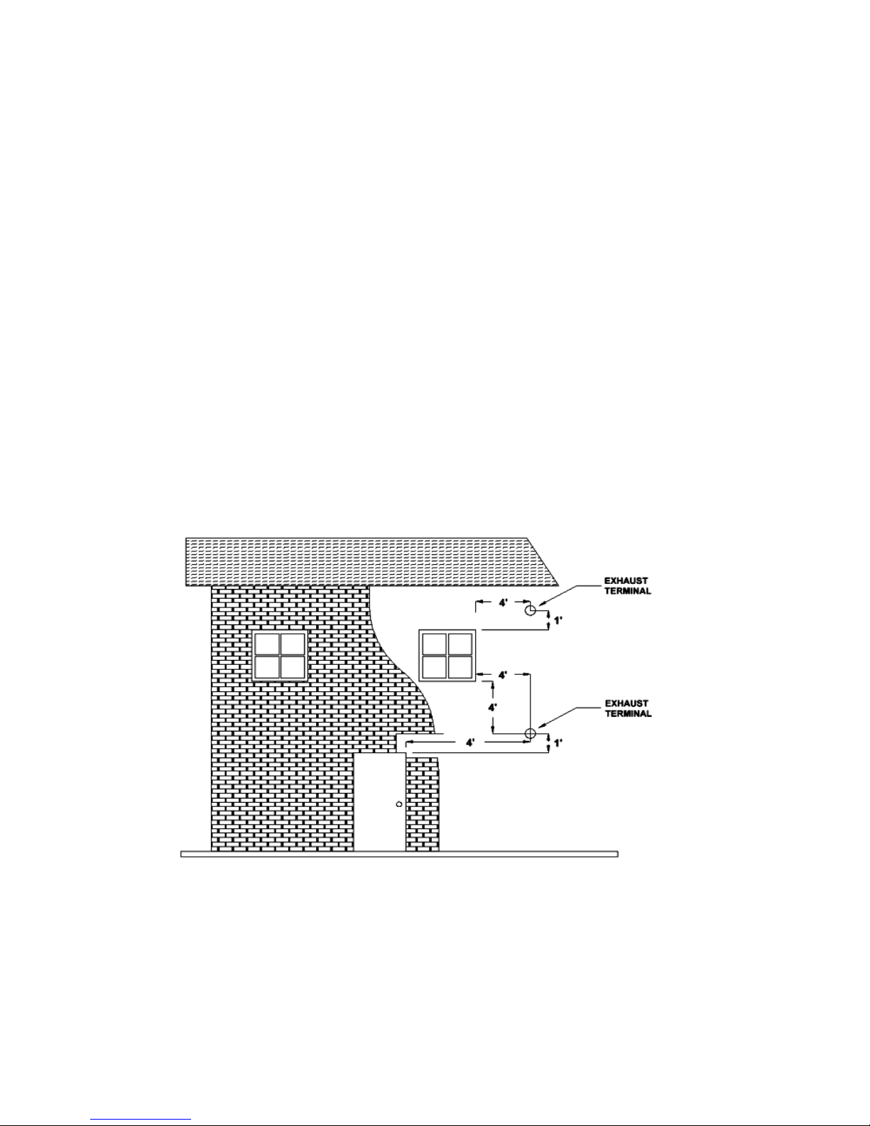
VENTING: TERMINATION REQUIREMENTS
In determining optimum vent termination, carefully evaluate external conditions especially when
venting directly through a wall. Since you must deal with odors, gases, and fly ash, consider
aesthetics, prevailing winds, distances from air inlets and combustibles, location of adjacent
structures and any code requirements.
1. Exhaust must terminate above combustion air inlet elevation.
2. Do not terminate vent in any enclosed or semi-enclosed area, (i.e. Carports, garage, attic
crawl space, etc.) or any location that can build up a concentration of fumes.
3. Vent surfaces can get hot enough to cause burns if touched by children. Non-combustible
shielding or guards may be required
The type of installation must first be considered before determining the exact location of
the venting termination in relationship to doors, window, cavities or air vents.
a. Without Outside Air connected to the unit. For this types of installation please refer to
the dimensions listed below in figure 4.
Figure 4
4’ (1.2 m) BELOW a door, window, cavity, or air vent
Or
4’ (1.2 m) HORIZONTALLY FROM a door, window, cavity, or air vent
Or
1’ (305 mm) ABOVE a door, window, cavity, or air vent
Element-MF Installation and Operations Manual
Page 13
Page 14
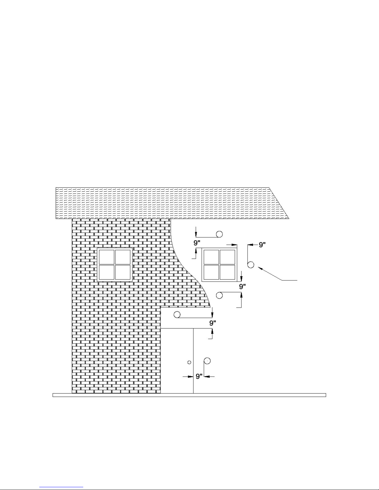
b. With Outside Air Connected to the unit. In this manner the appliance is a Direct Vent
Appliance (sealed Combustion System) as listed in NFPA 211-6.
3.3.3.2 Direct Vent Appliance (Sealed Combustion System Appliance) A system
consisting of an appliance, combustion air and flue gas connections between the
appliance and the outside atmosphere, and a vent cap supplied by the manufacturer, and
constructed so that all the air for combustion is obtained from the outside atmosphere
and all flue gases are discharged to the outside atmosphere.
Special Venting Arrangements are listed in NFPA 211-31
10.7.1.2 The Vent Terminal of a Direct Vent Appliance with an input of 10000 BTU/Hr or
less shall be located at least 6” from any opening into a building, and such an appliance
with an input of over 10000 BTU/Hr, but not over 50000 BTU/Hr shall not be located
less than 9” from any opening through which vent gases could enter a building, and the
vent terminal of such appliance with an input over 50000 BTU/Hr shall be located not
less than 12” from the opening.
Figure 5
9” (229 mm) ABOVE, BELOW OR HORIZONTALLY FROM a door, window, cavity, or air
vent.
Element-MF Installation and Operations Manual
Page 14
Page 15
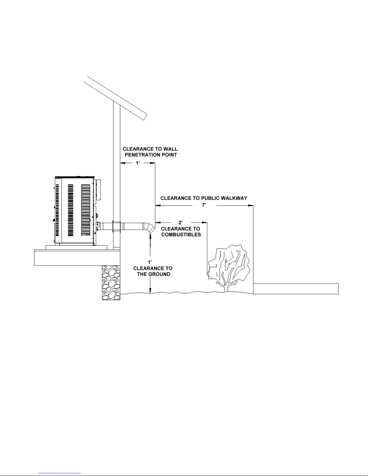
VENTING: TERMINATION CLEARANCE REQUIREMENTS
Figure 6
THE EXHAUST TERMINATION LOCATION MUST BE AT LEAST
1’ (305 mm) ABOVE the ground level
7’ (2.1 m) FROM a public walkway
1’ (305 mm) FROM The wall penetration point
3’ (915mm) FROM a gas meter/regulator assembly
2’ (610 mm) FROM any adjacent combustibles such as:
Adjacent buildings, fences, protruding parts
of the structure, roof eaves or overhangs,
plants, shrubs, etc.
Element-MF Installation and Operations Manual
Page 15
Page 16
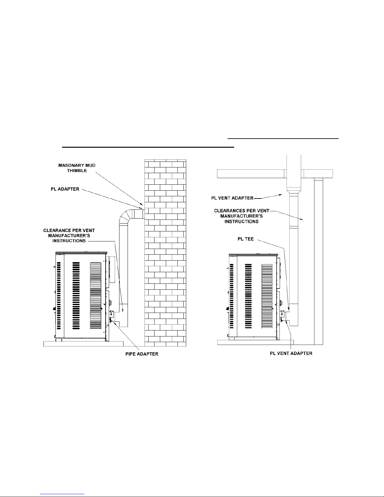
VENTING: INTO AN EXISTING CHIMNEY
The stove may be connected to an existing Class A chimney or a masonry chimney which meets
the minimum requirements of NFPA 211.
1. If the stove’s exhaust is connected to a masonry chimney, the masonry chimney must be
free of cracks that could leak exhaust gases or fly ash. A relining of the chimney with either
PL vent or single wall stainless steel pipe may be necessary to bring the chimney into
compliance.
2. When chimneys are relined, a chimney chase cap that reduces the outlet of the chimney to
the size of the liner is required. Extend the exhaust vent above the chimney chase cap and
finish it off with a rain cap. A single wall liner may need to be insulated to maintain
adequate exhaust temperatures in the vent system Note: Outside Chimneys frequently
are difficult to keep warm, if in doubt insulate the liner.
Figure 7 Figure 8
Venting into Masonry Chimney Venting into a Class A Chimney
3. Venting into the side of an existing masonry chimney must be done through a masonry
thimble. When wall penetration is necessary to access a masonry chimney, use a listed PL
vent wall thimble. (Figure 7).
4. When venting into a Class A steel chimney, use an appropriate PL Vent adapter. (Figure 8)
Element-MF Installation and Operations Stove
Page 16
Page 17
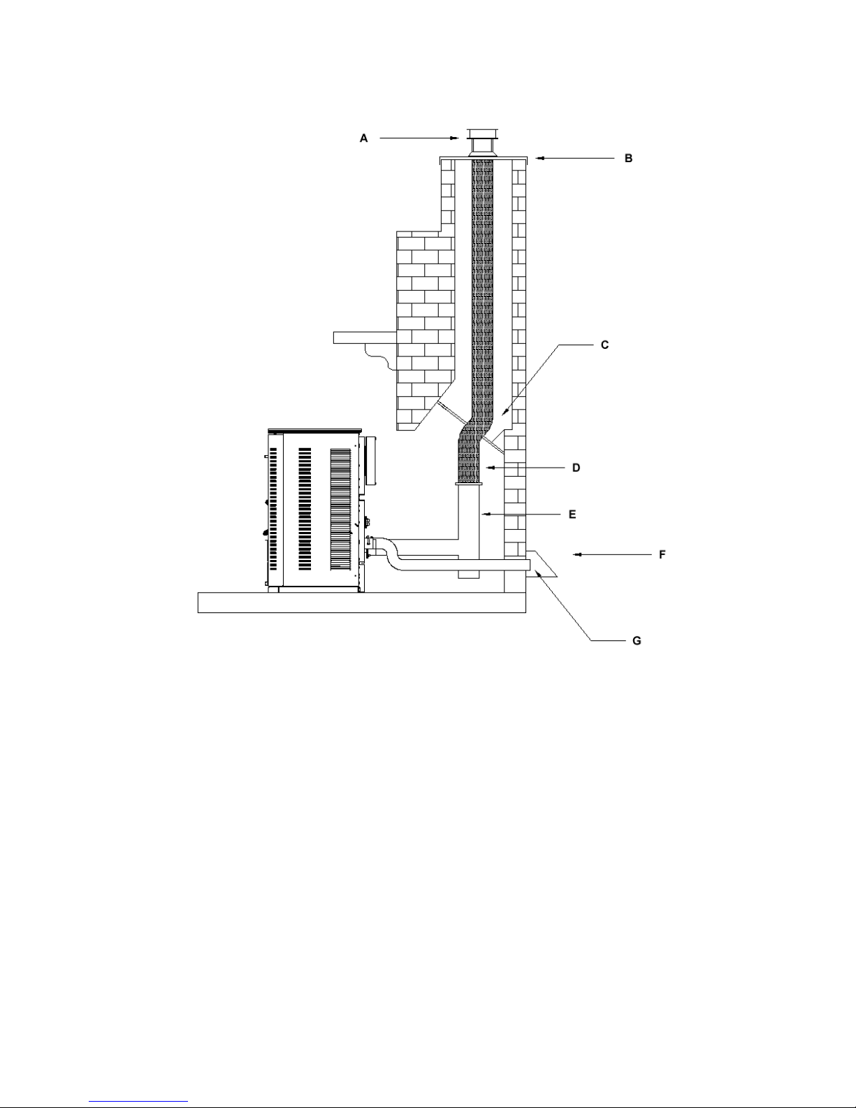
Hearth Mount
A – Vertical Cap
B – Chimney Flashing
C – Stainless Steel Liner / PL Vent System
D – Positive Block Off Plate
E – PL Tee or Single Wall Tee
F – Outside Air Shield – May be needed
G – 2” Metal Outside Air Pipe - Optional
Venting to the Top of Chimney
When installing as a hearth mount stove into a fireplace, the unit must either be relined
terminating above the chimney chase top, or positively connected to the existing chimney system
using a block off plate (C). An approved flex liner or PL vent must be used. A chimney system
with known drafting problems may require a liner, which may also need to be insulated to
keep vent system warm in a cold chimney environment.
Legend
Figure 9
Element-MF Installation and Operations Stove
Page 17
Page 18
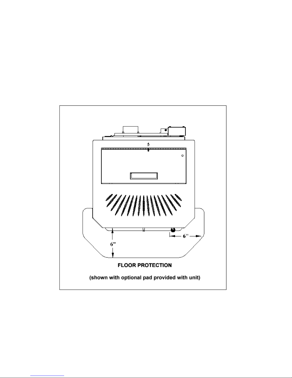
FLOOR PROTECTION
The stove must be installed on a Non-Combustible Surface.
Hearth models may be placed directly on the noncombustible hearth of a fireplace.
The Hearth / Non-Combustible pad must extend a minimum of 6” (152 mm) in Front of Unit and
beyond each side of the Fuel Loading and Ash Removal Opening(s).
Figure 10
Floor protection
(Top View)
Element-MF Installation and Operations Stove
Page 18
Page 19
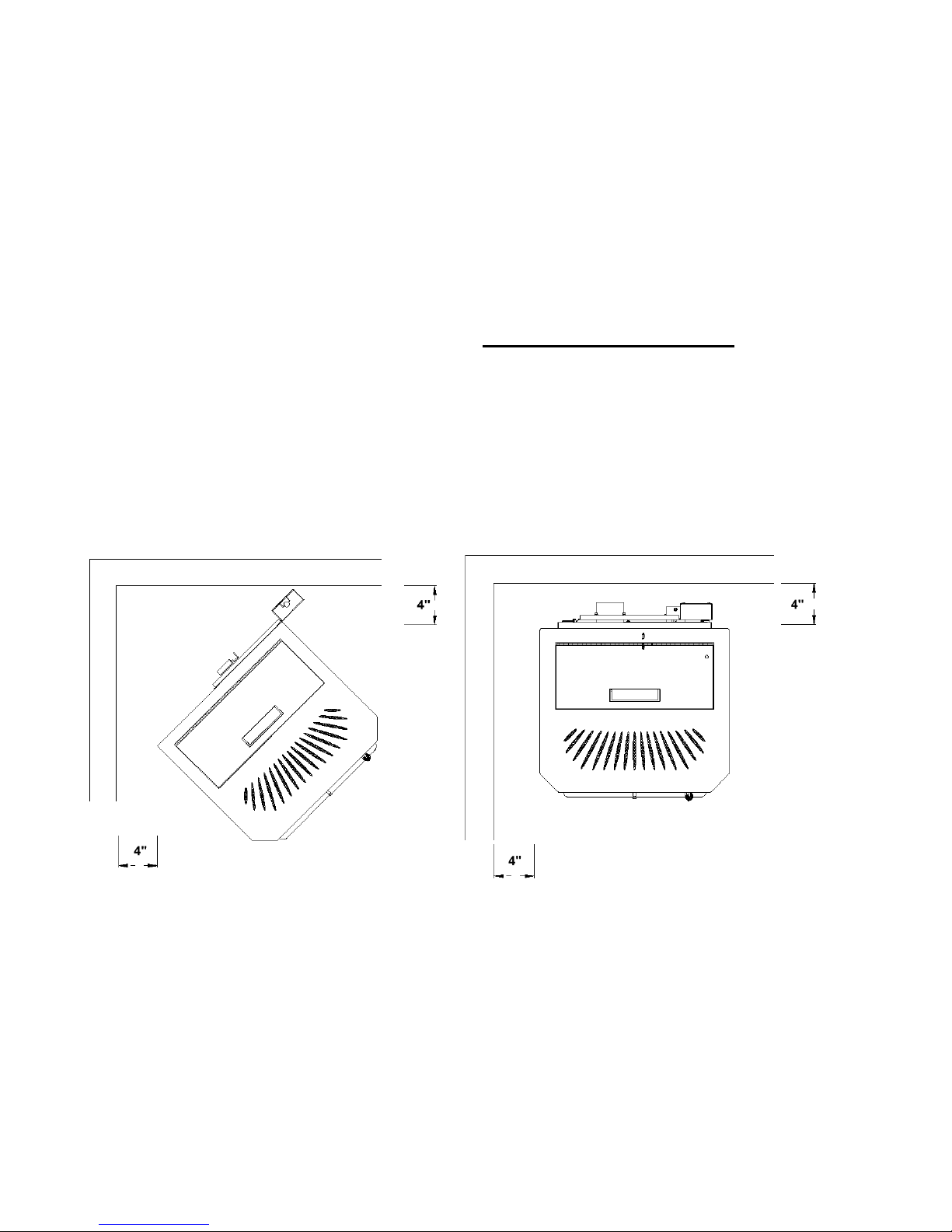
MINIMUM CLEARANCES (INCHES) TO COMBUSTIBLE MATERIAL
Figure(s): From:
12, 15 Sides of stove 4”
12, 15 Back of stove 4”
11 Corner of stove 4”
7, 8 Vent pipe Per Manufacturer’s Instructions
13 Stove to mantel 12”
10 Floor protection: Front (from faceplate) 6”
10 Floor protection: Sides & back of stove 0”
14 Alcove: Vertical to Combustibles 16”
15 Alcove: Sides 4”
15 Alcove: Back 4”
Figure 11 (Top View) Figure 12 (Top View)
Clearances: corners of stove Clearances Sides and Back
Element-MF Installation and Operations Stove
Page 19
Page 20
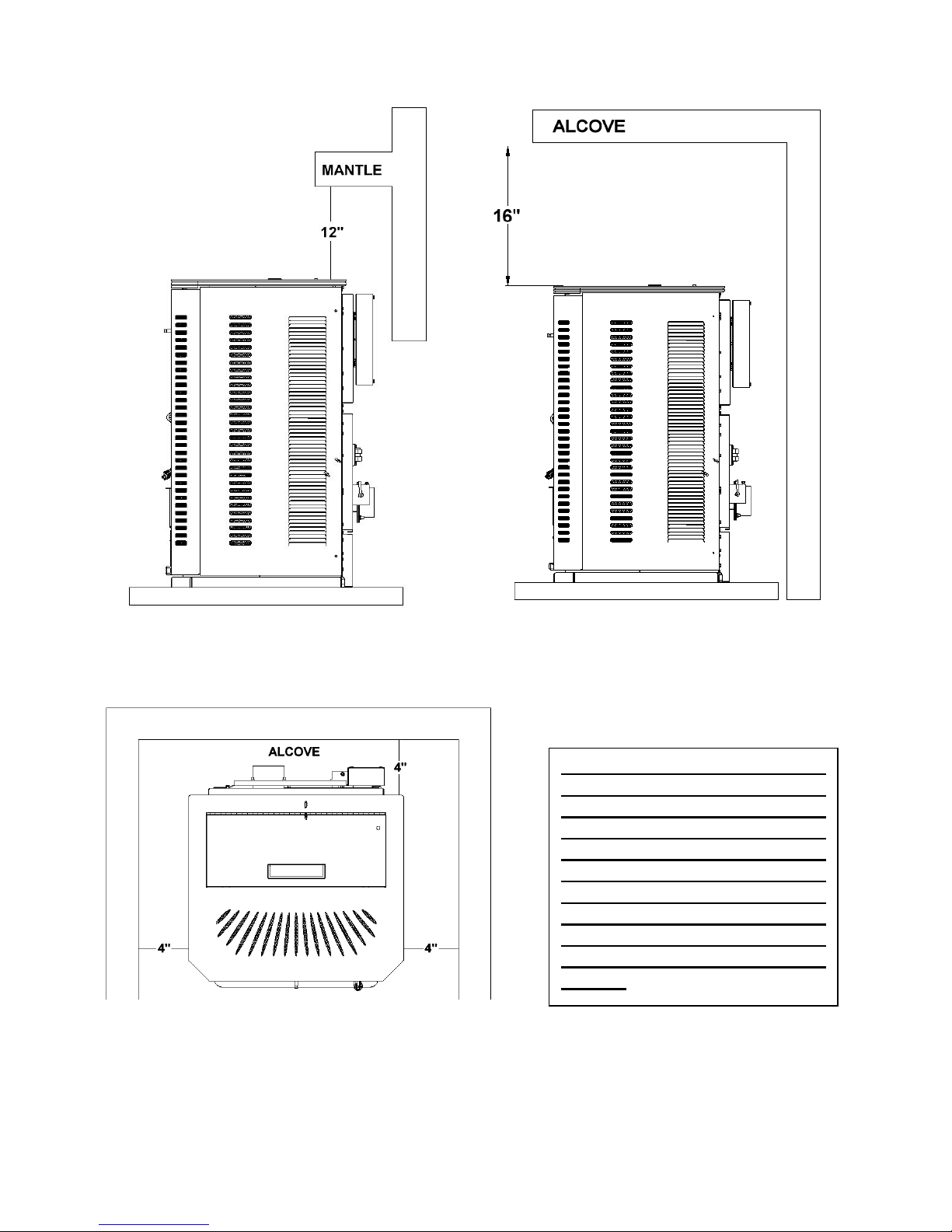
Floor Pad and Mantle Clearances Alcove Installation (Side View)
Figure 13 Figure 14
Although 4“ is the minimum
clearance to the sides of the stove,
this is not recommended due to
the need for access into the inside
of the stove for the maintenance,
as spelled out in the Operations
Manual. Please read the section
covering the Daily Maintenance,
Periodic Maintenance and Yearly
Maintenance in the Operations
Manual.
Figure 15
Alcove Installation (Top View)
Element-MF Installation and Operations Stove
Page 20
Page 21
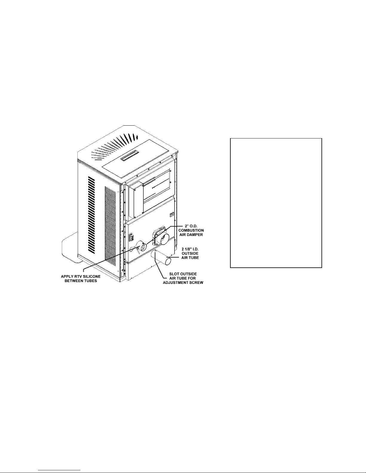
OUTSIDE COMBUSTION AIR
1. Under certain conditions it is recommended that the Element-MF be connected to an outside
source of combustion air to improve performance. Flexible metal hose, or rigid metal pipe,
(conduit), must be connected around (NOT INSIDE) the combustion air inlet tube. Be careful not
to pinch or bend the outside air pipe with too small a radius which may be terminated flush with
the outside wall but should be protected from wind and weather by a hood. Note: The outside air
pipe must terminate above the maximum snow line.
WARNING
USE THE AIR INTAKE
DAMPER FOR
ADJUSTING
COMBUSTION INLET
AIR ONLY! OTHER
METHODS OF
RESTRICTING OR
BLOCKING
COMBUSTION INLET
AIR ARE STRICTLY
PROHIBITED!
Figure 16
2. Outside air may be drawn from a semi-enclosed attic or crawl space or any semi-enclosed
space. Take care not to draw cold air past water pipes that may freeze.
3. Increase the outside air pipe diameter to 3” for runs over ten (10) feet and elevation over
4,000 feet. Note: Long runs should be avoided.
4. Terminate the outside air pipe below the exhaust vent outlet.
5. An open mesh screen should be placed over the outside air pipe opening to prevent birds or
rodents from nesting in the opening. Use an elbow or shield to prevent prevailing winds from
blowing directly into the outside air intake pipe. NOTE: Mesh screen should be no smaller than
one-fourth inch (1/4”) by one-fourth inch (1/4”).
WARNING: OUTSIDE COMBUSTION AIR IS REQUIRED FOR ALL MOBILE HOME INSTALLATIONS!
Element-MF Installation and Operations Stove
Page 21
Page 22
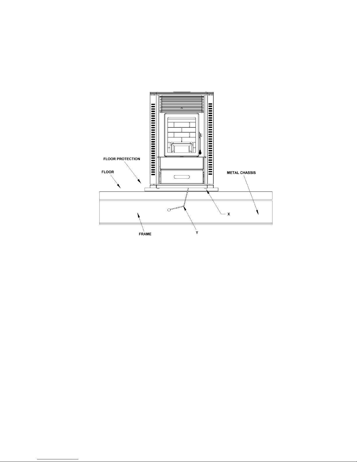
Mobile Home Installation
Unit must be installed in accordance with the:
Manufactured Home and Safety Standard (HUD), CFR 3280, Part 24
Unit may be installed in a Mobile Home, after the initial sale of the Mobile Home. Not for
use in Recreational Vehicles.
Figure 17
1. WARNING: DO NOT INSTALL IN A SLEEPING ROOM.
2. WARNING: COMBUSTION AIR MUST COME FROM THE OUTSIDE OF THE
MOBILE HOME! FAILURE TO DO SO MAY CREATE NEGATIVE PRESSURE
WITHIN THE MOBILE HOME AND COULD DISRUPT PROPER VENTING AND
OPERATION OF THE MULTI-FUEL STOVE.
3. CAUTION: THE STRUCTURAL INTEGRITY OF THE FLOORS, WALLS, CEILING
AND ROOF MUST BE MAINTAINED.
4. Permanently bolt the stove to the floor, (X).
5. Electrically ground the stove and pedestal to the metal chassis of the home. Use a number
eight, (8) gauge or larger copper wire, (Y).
6. Maintain an effective vapor barrier at location where PL vent exits the structure.
7. Check any other local building codes or other codes that may apply.
8. Do not use components other than those specified for use with this unit.
9. Floor protection requirements must be followed precisely.
10. PL Vent must be used for exhaust venting. (Single wall vent is not allowed). Follow PL
Vent manufacturer’s installation directions and observe all listed clearances to combustibles.
Element-MF Installation and Operations Stove
Page 22
Page 23

Element
-
MF
Operation
This Multi-Fuel heater needs periodic inspection and repair for proper operation. It is
against federal regulations to operate this Multi-Fuel heater in a manner inconsistent with
operating instructions in this manual.
The Stove is not warranted against damage caused by using poor quality fuel or other fuels
not approved for use in this Stove, incorrect operation, improper maintenance, or incorrect
installation.
CAUTION: Operate this unit only with the fuel hopper lid closed. Failure to do so may result in
emission of products of combustion from the hopper under certain conditions. Maintain hopper
seal in good condition. The auger will be prevented from operating by a hopper lid switch. Close
lid immediately after filling hopper with fuel.
This unit requires 120-volt AC power to operate. In the event of a power failure the unit will shut
down. DO NOT ATTEMPT TO RUN THE UNIT DURING A POWER FAILURE.
When burning corn, wheat or rye, care should be taken in how the venting system is installed. To
burn corn, wheat or rye the moisture content should be 15% or less. This can result in
condensation forming in the venting system in certain installations. The chimney system should
stay within the warm envelope of the house as much as possible. Only penetrate the exterior of
the home where the exhaust system will terminate.
REMEMBER: Condensation from burning Corn, Wheat, Rye or Distillers Grain is detrimental
to the venting system. Only buy Venting Systems that are warranted with burning corn.
PREVENTING CHIMNEY FIRES - Chimney fires can be prevented by properly operating
the Element-MF and by periodic inspection and cleaning of the chimney. When burning these
fuels tar and other organic vapors are produced, which combine with expelled moisture to form
creosote. The creosote vapors condense in the relatively cool chimney flue associated with a
slow burning fire. As a result, creosote residue accumulates on the flue lining. When ignited, this
creosote can result in an extremely hot chimney fire.
The chimney and chimney connector should be inspected at least once every two months during
the heating season to determine if a creosote build-up has occurred. If a significant layer of
creosote has accumulated (3 mm or more) it should be removed to reduce the risk of a chimney
fire. Use of an appropriately sized chimney brush or the services of a professional chimney
sweep are recommended.
The chimney and chimney connector should be inspected at least once every two months during
the heating season to prevent the system from getting plugged with Fly ash. Clean the exhaust
system if needed. Use of an appropriately sized chimney brush or the Services of a Professional
chimney sweep are recommended.
ELEMENT-MF APPROVED FUELS
SHELLED CORN - Shelled corn must be 15% or less moisture content. The keys to
satisfactory performance are: proper operation of the stove, diligent maintenance and burning
only dry, clean, quality corn. Corn dust must be screened prior to using.
Element-MF Installation and Operations Stove
Page 23
Page 24

NOTE: Corn with excessive grain dust must be screened, by sifting with 3/16" mesh
screening. Large pieces of cob may plug the auger.
Clinkers and Ash are a by-product of burning corn and are not caused by your stove. Stove
performance can be quickly and severely reduced if poor quality corn is used. Contact your
dealer for more information on where to get high quality corn to burn in your new corn stove.
Store approved fuels in a tight container use other methods to ensure they do not become rain
soaked or absorb moisture from damp or wet floors. This will also prevent rodents from
becoming a problem. Do not store approved fuels within stove installation clearances or
within the space required for clinker removal.
The stove is not warranted against damage caused by poor quality fuel, using fuels that are
not approved for the unit, incorrect operation, poor maintenance or incorrect installation.
CHERRY PITS - No Standard exists for Cherry Pits used as Fuel. Inspect fuel before buying.
When burning cherry pits or any other fuels mixed with cherry pits, the side shields must be
removed. Failure to remove the side shields will prevent fuel from spilling into the Ashpan in the
event the pot overloads. See figure 2 on page 8 showing the removal of the side shields. The
shields lift up and are removed without needing any tools.
DISTILLER’S GRAIN - No Standard exists for Distillers Grain used as Fuel. Inspect fuel
before buying.
When burning Distiller’s Grain or any other fuels mixed with Distiller Grain the side shields
must be removed. Failure to remove the side shields will prevent fuel from spilling into the
Ashpan in the event the pot overloads. See figure 2 on page 8 showing the removal of the side
shields. The shields lift up and are removed without needing any tools.
Distiller’s Grain is a byproduct of producing Ethanol and has higher oil content than corn itself.
Due to this the stove may require more frequent cleaning. Soot may rapidly form in the exhaust
system if the air is not set properly. Check the exhaust frequently when burning Distiller’s Grain.
WHEAT - No Standard exists for Wheat used as Fuel. Inspect fuel before buying. Wheat is a
small grain and burns in a similar manner as corn. It forms a clinker in the burnpot that is tends
to stick to the sides of the pot. When dropping the Clinker it may need to be pushed into the
Ashpan using a long narrow screwdriver or a similar tool. Wheat is a small lightweight grain,
more residue will blow out of the burnpot as it burns. If an excessive amount seems to be
blowing out of the pot, adjust the damper by closing it a small amount at a time. (Read the
section covering the Combustion Air Damper on page 30 - 32)
RYE - No Standard exists for Rye used as Fuel. Inspect fuel before buying. Rye is a small grain
and burns in a similar manner as corn. It forms a clinker in the burnpot that is tends to stick to the
sides of the pot. When dropping the Clinker it may need to be pushed into the Ashpan using a
long narrow screwdriver or a similar tool. Rye is also a small lightweight grain more residue will
blow out of the burnpot as it burns. If an excessive amount seems to be blowing out of the pot,
adjust the damper by closing it a small amount at a time. (Read the section covering the
Combustion Air Damper on page 30 - 32)
Element-MF Installation and Operations Stove
Page 24
Page 25

Clinkers and Ash are by-products of combustion and are not caused solely by your Stove. Stove
performance can be quickly and severely reduced if poor quality fuel is used. Contact your dealer
for more information if you experience problems with one of the fuels listed above.
Do Not Use Chemicals or Fluids to Start The Fire.
Do Not Burn: Garbage, Gasoline, Naphtha, Engine Oil, Lawn Clippings, Yard Waste, Rubber,
Plastic, Waste Petroleum Products, Paints or Paint Thinners, Asphalt Products, Construction or
Demolition Debris, Railroad Ties, Pressure Treated Wood, Plywood, Particle Board, Manure or
Animal Remains, Paper Products or Cardboard.
Burning the above materials may result in release of toxic fumes or render the heater ineffective
and cause smoke.
The prohibition against burning these materials does not prohibit the use of fire starters made
from paper, cardboard, saw dust, wax and similar substances for the purpose of starting a fire in
an affected Multi-Fuel heater.
INSTALLATION CHECK - Proper installation is essential for safety, effective Operation,
Warranty Coverage, Insurance requirements and to meet Local Building Codes. Installation
Requirements are described in the first section of this manual. Verify the installation is correct
before firing up the Stove for the first time.
1. The fans of this Stove may cause a negative pressure area in the room where this Stove is
installed.
2. Outside Combustion Air may be needed if:
- The unit does not vent steadily, smells, experiences smoke rollout, burns poorly, or back-drafts
whether or not there is combustion present.
- Any of the symptoms listed above are alleviated by opening a window slightly on a calm day.
- The house is sealed with a well-sealed vapor barrier and tight fitting windows and doors and/or
has any powered devices, which exhaust house air.
- There is excessive condensation on the windows during the winter.
- A ventilation system is installed in the house- Adhere to all Clearances and Restrictions
specified in the Installation Instructions of this Stove.
When storing fuel be sure to use sealed containers in a dry environment to prevent the fuel from
absorbing moisture and becoming damaged. Do not store bags of starter pellets directly on
concrete.
- Establish a routine for the storage of fuel, care of the Stove and Firing Techniques.
- Check daily for creosote build-up until experience shows how often cleaning is necessary.
- Be aware that the hotter the fire, the less creosote is deposited, and that weekly cleaning may be
necessary in mild weather, even though monthly cleaning may be enough in the coldest
Element-MF Installation and Operations Stove
Page 25
Page 26
months. Run the Stove on the hottest setting once a day for 30 – 45 minutes to prevent
excessive build-up in the Stove.
- Have a clearly understood plan to handle a chimney fire. Contact the local fire department for
information if needed.
- Keep the doors closed and all seals in good condition while operating the Stove.
- INSPECT THE FLUE PIPES, JOINTS AND SEALS REGULARLY TO ENSURE THAT
SMOKE AND FLUE GASES ARE NOT DRAWN INTO, AND CIRCULATED BY THE
AIR-CIRCULATION SYSTEM.
- CLEANING OF THE HEAT EXCHANGER, FLUE PIPE, CHIMNEY AND DRAFT
INDUCER IS ESPECIALLY IMPORTANT AT THE END OF THE HEATING SEASON TO
MINIMIZE CORROSION DURING THE SUMMER MONTHS CAUSED BY
ACCUMULATED ASH.
- The Stove will not operate during a power failure. Prolonged Power Outages will require the
use of a generator to operate the Stove.
Control Board Features
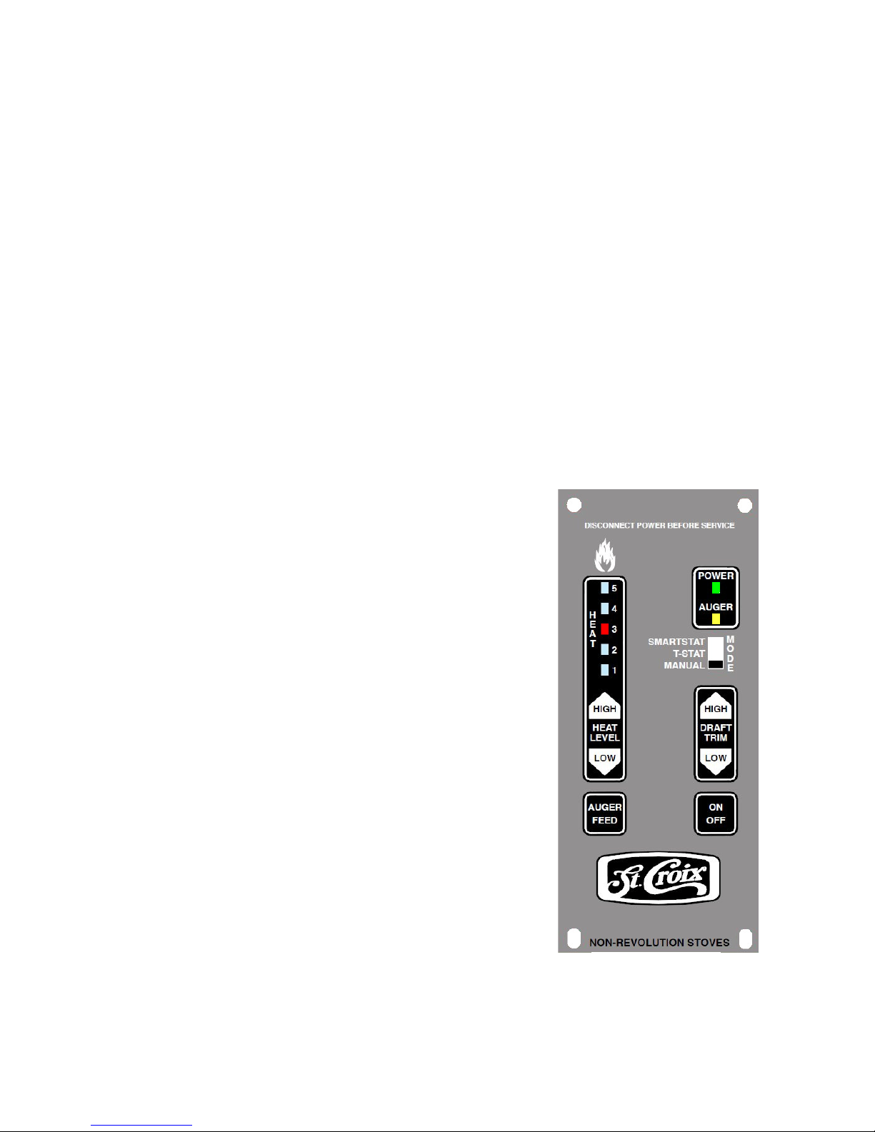
The Control Board controls all functions of the
Element-MF by monitoring sensors that are in the
system. These sensors serve 2 purposes.
a. General Operation of the Stove.
b. Safety Features, to shut the unit down in
the event the sensors detect a problem in the unit.
The Control Board also has Diagnostic
Capabilities to help in diagnosing 3 areas of the
Multi-Fuel Stove. These areas are:
1. High Temperature Limit.
2. Proof of Fire Sensor
3. Vacuum in the Firebox
A closer look at the Control Board to the right in
figure 18 will explain how the board works. There
are essentially 4 buttons on the control board.
Two of these buttons, the Heat Level and Trim
Buttons, have a High/Low side to advance these
settings up or down. There is a Slide Switch that
controls the Thermostat Mode and an LED Light
bar that indicates which of the 5 Heat Settings the
Element-MF is running on.
The LED Light bar is also used during the Diagnostic process, see page 34-35 for more details
Figure 18
Element-MF Installation and Operations Stove
Page 26
Page 27

1. The Heat Level button will advance the setting up and down between level 1 and 5. It will
also be used in the Fine Tuning process of the feed rates if needed.
a. To adjust the Feed-rates: Hold the Auger Feed Button down and press the Heat Level
High/Low button and this will change the ON Time up or down .25 seconds from the factory
setting. Watch the LED lights to see the setting is on (it will flash the new setting). This new
setting will stay in memory from this point on.
2. The Auger Feed button will allow the user to manually auger fuel into the burn pot on start
up when needed. This is particularly helpful in priming the Auger Tube when it is empty (After
the hopper has run out of fuel). Do not tamper with the Auger Feed button to override the
automated feed system. This may cause the unit to Overheat.
To adjust the Feed-rates:
Hold the Auger Feed Button down and press the Heat Level High/Low button and this
will change the ON Time up or down .25 seconds from the factory setting. Watch the
LED lights to see the setting is on (it will flash the new setting). This new setting will
stay in memory from this point on.
3. The On/Off button not only turns the Stove On and Off, it also resets the board if one of the
sensors has detected a problem and the board is flashing a Diagnostic code.
4. The Draft Trim button allows for adjusting the Exhaust (Combustion) fan voltages up or
down providing for fine-tuning of the combustion air. The LED light bar indicates the level of
adjustment and the factory setting is the center LED light. This allows for 2 adjustments up and 2
adjustments down. (See point 9 on page 48)
To adjust the Combustion Fan voltages:
Hold the Auger Feed button down and press the Draft Trim High/Low button and this will
change the fan voltage approximately 2.5 volts up or down from the factory setting. Watch
the LED lights to see the setting is on (it will flash the new setting). This new setting will
stay in memory from this point on.
5. The Thermostat Slide switch allows the Stove to be run in 3 different Modes:
a. Manual Mode. The Control Board controls all functions of the Element-MF.
b. T-Stat Mode. The Multi-Fuel Stove is hooked to a Thermostat and when calling for heat
the Element-MF will advance to the Heat level set at the Control board. Once the Heat
demand has been met the Stove will drop to the #1 Heat Level setting and pilot. The Stove
never shuts off and provides constant heat.
c. SmartStat Mode. Do not use this setting with the Element-MF. This Thermostat mode
may only be used with Pellets in a unit with the Versa Grate System & Igniter installed
Pre-Lighting Instructions
The Control Board has 4 separate program-. Two of the programs are for the Element-MF
(Programs 1 & 2) and two of the programs are for the Element-P (Programs 3 & 4). Before
Element-MF Installation and Operations Stove
Page 27
Page 28
lighting the Stove for the first time, ask your dealer about how to change the program or read the
instructions on the following page. The unit is set to the default program, which is program 1.
There is no feature to check to see which program is running. You must change it to see what
program was running and then cycle back through the programs to revert to program 1.
The Cycle time is the total of the ON Time & OFF Time added together. The ON Times are
constant, so this means that the OFF Time is increased or decreased, depending on the program
chosen.
Program 1. The Cycle Time is 11.5 seconds. This is the default program when the Element-MF
is first plugged in. This program does not offer self-ignition. This program is for use with Corn,
Wheat and Rye, Cherry Pits & Distillers Grain.
Program 2. The Cycle Time is 13 seconds. This program does not offer self-ignition. This
program is for use with Corn, Wheat and Rye, Cherry Pits & Distillers Grain.
Program 2 is for adjusting for variations that occur within the approved fuels for this unit. Ask
your dealer before using this Program in your unit. Program 2 is for “Tweaking” the unit for
different fuel and installation conditions.
Program 3. The Cycle Time is 11.5 seconds. THIS PROGRAM IS ONLY TO BE USED WITH
THE ELEMENT-P. (DO NOT USE THIS PROGRAM WITH THE ELEMENT-MF).
Program 4. The Cycle Time is 10 seconds. THIS PROGRAM IS ONLY TO BE USED WITH
THE ELEMENT-P. (DO NOT USE THIS PROGRAM WITH THE ELEMENT-MF).
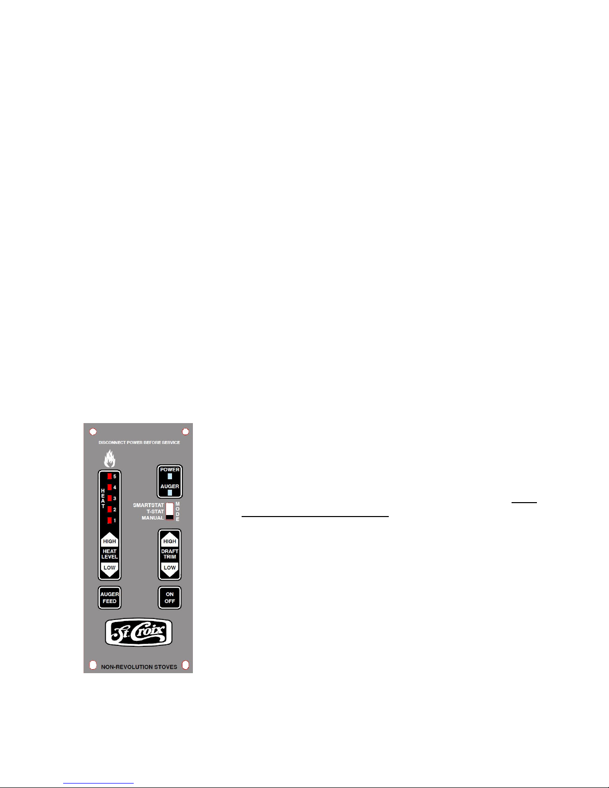
Changing the program on the Control Board
To change the program the Stove must be in the OFF
position, the unit must be cooled down so the Proof of Fire
disc is open and the Thermostat Slide Switch must be in the
Manual mode. (See figure 19)
Press & hold the Auger Feed Button, then press AND
IMMEDIATELY RELEASE the Trim High & Low Button
at the same time. The 5 LED lights that indicate the heat
levels will flash. The number of times the lights Flash will
indicate which program is running.
Program 1 – LED lights flash once
Program 2 – LED lights flash twice
Program 3 –LED lights flash three times
Figure 19
Program 4 –LED lights flash four times
Element-MF Installation and Operations Stove
Page 28
Page 29

Lighting Your Stove with the Multi-Fuel Burn Pot.
WARNING: - Risk of Fire.
-Do not operate with the Firebox door or Ash Removal doors open
-Do not store Fuel or other Combustible material within marked Installation Clearances.
-Inspect and Clean Flues and Chimneys regularly.
Danger: Risk of Fire or Explosion - Do not burn Garbage, Gasoline, Drain Oil or other
Flammable Liquids.
WARNING: Do not bypass the hopper lid switch. The auger can start at any time while the
Stove is running. The auger motor is a high torque motor that is capable of doing
SERIOUS harm to fingers. Keep fingers and other objects away from the auger.
When lighting your Stove for the first time the auger tube will be empty. Hold the Auger Button
in until you hear fuel drop into the burn pot.
1. Make sure there is corn in the hopper.
2. Add one cup of Starter Pellets to the burn pot (using pellets to start the unit is approved). Do not try to
start your stove with corn or other small grains, because Grain is difficult to start. Add a generous amount
of starter gel to the pellets.
4. Close the door and push the On/Off button on the control board. (See figure 18 on page 26)
5. Set the controls to Heat Level #1
6. Once the Proof of Fire switch locks in and the Power Light quits blinking, adjust the heat level to
the desired level.
The Ignition Cycle works as follows:
a. The Combustion Fan comes on at high speed and the control board checks to make sure
the Vacuum switch locks in. (See section on Diagnostic features on page 34 and 35)
b. If the Control Board senses the Vacuum switch the Exhaust Fan drops to a lower start up speed
and the Room Fan shuts off.
c. After 5 minutes the board starts feeding Fuel on the #1 setting until the board senses Proof of Fire
or until the ignition cycle times out after 15 minutes.
d. If the board fails to sense P.O.F. after 15 minutes it will shut down and flashes the #3 alarm.
e.
If the board senses P.O.F. the stove has started successfully and the Igniter shuts off. The
unit is now in “Normal Operation Mode”.
If the Stove went into “Shutdown” and the #3 LED is flashing (See section on Diagnostic
Features on page 34 and 35.) repeat the Start-Up process.
CAUTION: NEVER ADD FIRE STARTER TO A HOT STOVE.
Element-MF Installation and Operations Stove
Page 29
Page 30
Shutting the Unit Off
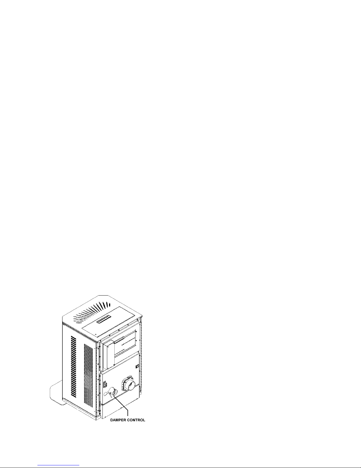
Figure 20
1. Press the On/Off switch once; the lights will go off and the fire will go out in a few minutes.
The board essentially goes into “Safety shutdown”.
2. As long as the temperature within the Element-MF remains above 110°F the both Fans will
continue to run. When the P.O.F. switch drops out, the room fan shuts of and the Combustion fan
will run for another 10 minutes and finally shut down completely.
NEVER unplug the Stove to shut it off. Doing so may cause smoke to enter the room.
Importance of proper Draft
Do not neglect to adjust the Combustion Air Damper during the break in period of your new
Stove (See Figure 20). Your Stove is equipped with an air inlet damper. The purpose of this
damper is to adjust combustion airflow to match the characteristic of each specific air inlet and
chimney configuration. See figure 20 for initial damper settings for your fuel. The damper will
most likely only need a small adjustment during the break-in period. Break-in requires the
burning 15 bags of fuel or a continuous burn for two weeks.
If you notice a difference in the operation of the Stove, first check to see if there has been a
change in the fuel you are burning. If the fuel properties have significantly changed, such as the
fuel is very dirty, then making a change to the damper is correct.
However if the Stove needs cleaning, changing the Damper may mask the fact that the stove is
getting plugged. It is always a good idea to thoroughly clean your stove before making a
significant damper change.
If you experience problems adjusting the Stove during the Break-In Period, contact your
dealer. Some chimney systems will fall outside the norm, for example, a chimney with excessive
draft or one with a long horizontal run.
Initial damper settings for a stove using a Horizontal Vent system
F
irst note the location of the set screw. This screw is
turned in until it stops against the tube. Moving the
screw is normally not needed.
Heat level 1: Open the damper 1/8 of an inch.
Heat level 2: Open damper to 3/16 of an inch.
Heat level 3: Open damper to 3/16 of an inch.
Heat level 4: Open damper to 1/4 of an inch.
Heat level 5: Open damper to 5/16 of an inch.
Observe the flame and adjust the damper from these
positions if needed based on “Flame Pattern
Characteristics listed on the next page. Adjust the
damper 1/16 of an inch at a time and wait 5 minutes
between adjustments to allow the pot to balance out.
Element-MF Installation and Operations Stove
Page 30
Page 31

Stoves connected to Vertical Vent systems should use reduced damper settings. Close the
damper a 1/16” – 1/8” to compensate for the natural draft of the vertical chimney.
Procedure for adjusting the damper for burning Grains and Cherry Pits - When burning
Corn, wheat, rye & Distiller’s Grain the burn pot should be “Balanced”. This means the fuel that
is being fed into the burn pot rapidly turns into glowing coals. If you see a lot of unburned fuel in
the pot, an adjustment may be needed. In an unbalanced pot, the corn, wheat or rye will quickly
stick together and prevent the proper flow of combustion air. The pot will overload and the fire
will go out.
Conditions indicating Inadequate or Excessive Draft
When burning Corn, Wheat, Rye or Distiller’s grain the effects of inadequate and excessive draft
will be the same. The pot will overload (see point 3 below) and the fire will go out. The rule of
thumb is to make small adjustment to open the damper if the vent is horizontal and to make small
adjustments to close the damper if the vent terminates above the roof.
1. Balanced burn pot. This means the fuel rapidly turns into red-hot coals once it is in the pot.
2. Lag time. This is the time it takes for the corn to start burning and the burn pot to become
balanced. Corn will tend to stick together in a clump in the burn pot if the corn feeds in faster
than it’s burning.
3. Overloaded burn pot. If the corn forms a clump in the burn pot it chokes off the airflow
and the pot will overload and slowly the fire will die out.
Set the damper according to the list “Initial Damper Settings” on the previous page.
a. Once the Stove is burning, leave the control board on the #1 setting for ½ an hour. This will
allow the Stove to warm up before any adjustments to the damper are made. After ½ an hour,
look in the burn pot to see if the burn pot is balanced. The Stove should be burning fine and an
adjustment is most likely not needed. Make note of any damper changes you make at each heat
level for future reference.
b. Advance the heat setting to #2 and let the Stove burn at this setting for ½ an hour. Check
the burn pot to see if it is balanced. Most likely the Stove will be burning fine at this point.
c. Advance the heat setting to #3 and let the Stove burn at this setting for ½ an hour. Check
the burn pot to see if it is balanced. Remember: Look at the coals in the pot, not at what the
flame looks like. Most likely the damper will not need to be adjusted.
d. Advance the heat setting to #4 and let the Stove burn at this setting for ½ an hour. Check to
see if the pot is balanced. This is where a damper adjustment might need to be made. As the
heat setting reaches the higher settings the “Lag time” can become too long if the air isn’t
adjusted correctly. If you notice that the coals are being covered up with unburned fuel, adjust
the damper to give it more air by sliding the damper control 1/16” only
If the grain has formed a clump in the pot, use a screwdriver to break up the clump of fuel to
allow for proper airflow). Wait 15 minutes to see if the burn pot becomes balanced. Repeat this
step as many times as needed until the burn pot becomes balanced.
Element-MF Installation and Operations Stove
Page 31
Page 32

e. Advance the heat setting to #5 and let the Stove burn at this setting for ½ an hour. Check
the burn pot to see if it is balanced. A small damper adjustment might need to be made at this
time to make sure the “Lag time” isn’t too long. Remember: only adjust the damper 1/16” at
a time and wait 15 minutes to see if the burn pot becomes balanced. Repeat this step as many
times as needed until the burn pot becomes balanced.
Additional draft adjustments can be made using the Draft trim feature built into the control
board. Read point 4 on page 27 and read the “Frequently Asked Questions” in the back of the
manual.
Flame Pattern Characteristics
Correct Flame Pattern - Bright yellowish-white flame with a brisk movement, having sharp
pointed end tips extending up towards the Heat Exchange Tubes while forming a fan-like shape.
Small amounts of ash and some live sparks being blown out from the Burn Pot area is considered
normal operation.
Incorrect Flame Pattern - Dark Orangish-Brown flame with a lazy movement, having black
smoky end tips curling up and over the Heat Exchange Tubes while forming a fireball-like shape.
Some Ash or Live Sparks not being blown out from the Burn Pot area is considered abnormal
operation. Excessive black soot forming on the ceramic glass surface is a sign of very poor
combustion (not enough combustion air) and should not be overlooked.
At the other end of the spectrum; an extremely brisk flame which blows large pieces of live coal
out from the Burn Pot area and causes stubborn shiny black build-up on the glass (too much
combustion air) is also considered undesirable and requires the damper to be closed.
If you experience problems adjusting the stove during the Break-In Period, contact your
dealer.
USE OF A THERMOSTAT
The Element-MF offers the optional feature of thermostatically controlling your new stove. By
using a thermostat to control the operation of your Stove you can benefit two ways. First of all,
after setting the thermostat to your desired heating needs, the stove will operate accordingly to
uniformly maintain your desired temperature setting. Secondly, the fuel consumption is being
optimized, which ultimately results in lowering your seasonal heating costs.
While the room temperature remains cooler than your desired thermostat setting, the stove will
operate at any of the 5 HEAT ADJUST selector positions. Read the Operations manual to
determine which Thermostat Mode you want to use. You can choose between the T-Stat Mode
and the SmartStat Mode.
1. Once you have successfully lit your stove, set the thermostat to your desired heating needs.
2. Set the HEAT ADJUST selector to a position that will effectively create a rise in room
temperature above your thermostat setting. The recommended heat settings while using a
thermostat are any position between 2 through 5.
Element-MF Installation and Operations Stove
Page 32
Page 33
Thermostat Hook-up
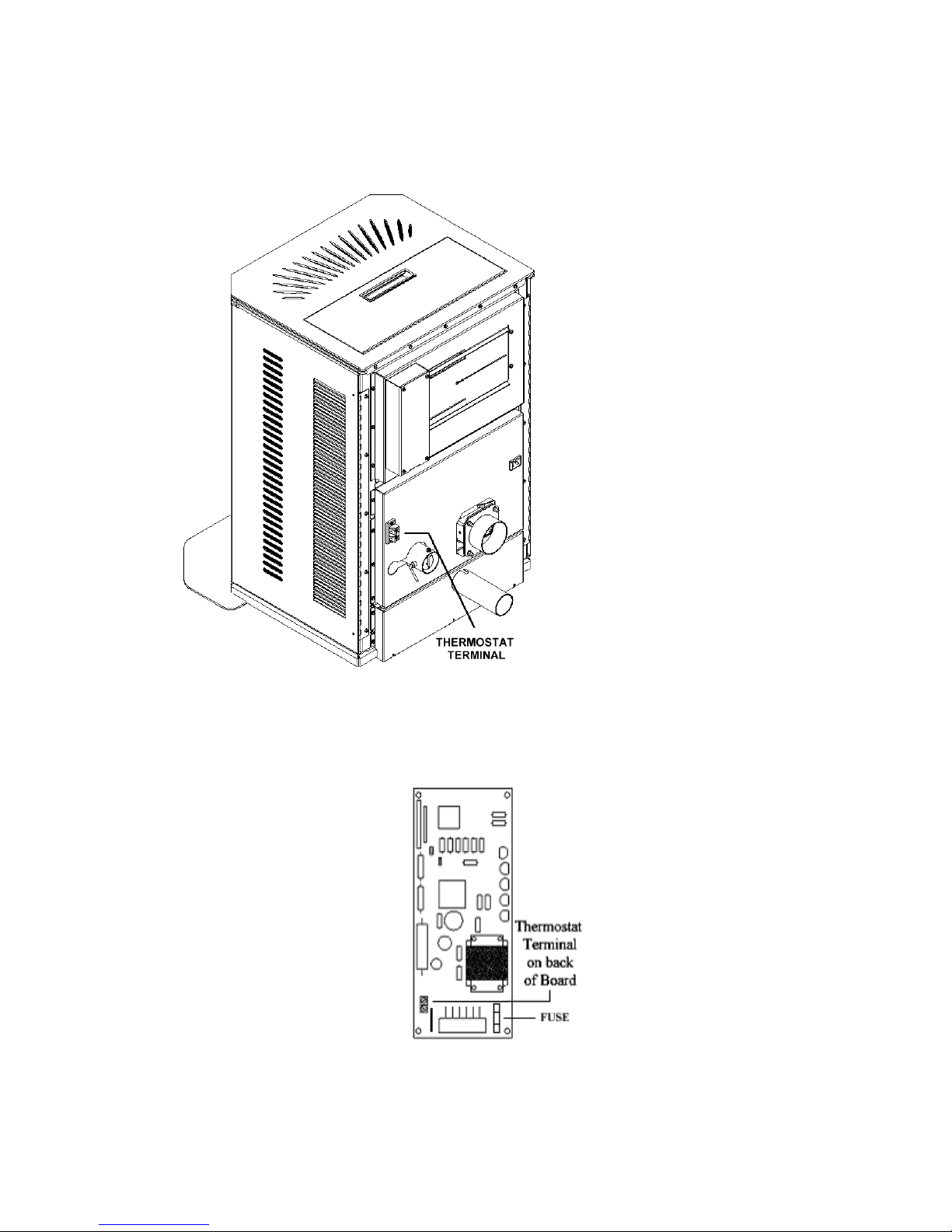
Connect the wires from the thermostat to the external wire terminal on the back of the stove (see
figure 21).
The external Thermostat wire terminal has been pre-wired to the thermostat wire Terminal on
the back of the control board (See figure 22)
Read Frequently Asked Questions section in the Operations Manual to Troubleshoot the
Thermostat.
Figure 22
NOTE: Installers must determine a neutral location of where to mount the thermostat
for accurate room temperature measurements.
Figure 21
Element-MF Installation and Operations Stove
Page 33
Page 34

Thermostat Control & Pilot Settings
The Stove may be controlled with a thermostat to help maintain a more constant temperature.
The Stove will react a little slower to a thermostat compared to a Gas or Electric Stove. With this
in mind the low setting can be adjusted to increase or decrease the amount of fuel used. This will
allow the heat output during the pilot stage to be matched to the size of the home. A larger home
will require more heat than a small one. Keep in mind that the Stove is constantly producing
some heat that helps heat the home while it is in pilot mode. If the home seems too warm, and
the Thermostat is never calling for heat, a lower pilot setting may be a better fit for the home.
(Read point 2 on page 27 for adjusting the feed rates on the low setting).
Remember: Choosing a lower Pilot setting may require the Draft Fan Voltage or the
Damper to be fine-tuned to match the lower feed rate. Monitor how the Stove is
operating after a change is made and adjust the damper or Combustion Fan voltage
accordingly.
Diagnostic Features and Safety Sensors.
The #2 LED, #3 LED, #4 LED and #5 LED lights on the LED Light bar will flash to give a
diagnostic code to help in diagnosing problems that may occur. (Read Frequently Asked
Questions for more information)
These conditions fall into 3 categories:
a. Heat related issues.
b. Vacuum related issues.
c. Plugged Stove issues.
The Diagnostic Lights flash as follow:
1. The Vacuum switch. For the Stove to operate correctly the firebox needs to be sealed.
During the first 30 seconds after the unit has been turned on, the control board will check to see
if the switch senses negative pressure (Vacuum) in the firebox of the Stove. If there is no
negative pressure, the Stove will go into “Safety shutdown” and the #2 LED will start blinking.
(Read Frequently Asked Questions for more information) A 60 second delay has been
incorporated before the unit shuts down when the board senses loss of vacuum. This is to
accommodate opening the doors during maintenance. Once the board senses loss of vacuum, the
ON/OFF light will start blinking. While the light is blinking the control board will not feed any
fuel nor respond to any of the buttons. Once Vacuum has been restored the unit will revert back
to normal operation.
2. The Proof of Fire switch. This switch will sense the temperature of the Exhaust rising
during start up. If the Exhaust temperature does not reach 110 degrees F, or if during use, the
temperature drops below 110 degrees F, the Stove will go into “Internal Alarm” and the Auger
will quit feeding fuel. Once the Stove completes the safety shutdown the #3 LED will start
blinking. (Read Frequently Asked Questions for more information))
Element-MF Installation and Operations Stove
Page 34
Page 35
3. The High Limit switch. This sensor will sense if the unit reaches temperatures that are too
high for normal operation. If this happens the Auger will quit feeding and the #4 LED light will
start blinking. (Read Frequently Asked Questions for more information)
4. The SmartScan Maintenance Sensor
- Patent Pending
. This sensor monitors the burn pot area
inside the firebox. If it senses Maintenance issues within the stove, that cause improper burning
conditions in the firepot, the unit will shut down and flash a #5 LED.
Check all Maintenance areas of the stove and the venting system for any conditions that can
cause improper burning, such as, gaskets, door latch, ash pan latch, ash traps, ash clean out
covers, plugged vent, plugged vent caps etc.
St Croix SmartScan Maintenance System - “Pre-emptive Monitoring” is an innovative way of
detecting when the unit is burning incorrectly.
The following situations can affect the way a Pellet Stove burns: Operator Error, Poor Fuel
Quality, a Plugged Venting System, a Plugged Stove, a Dirty Burn Pot, Worn Door Gaskets,
Worn Glass Gaskets or Weak Combustion Fan.
How does it work? - The area monitored is inside the Firebox/Burnpot area, directly above the
back edge of the burn pot.
The SmartScan Infra Red sensing system is very accurate. The monitoring takes place from a remote
location; it can sense an object as small as one pellet and does not depend on sensing temperatures.
Temperature sensing is difficult at this location, because it monitors an area that fluctuates between
extremely hot temperatures during High Burn and lower temperatures in the pot during Low Burn.
By monitoring this area, the stove will shut down when conditions in the Burn Pot fall outside of the
Normal Operating range. Shutting the unit down when fuel reaches this level, will trigger a diagnostic
code that notifies the operator that the stove needs maintenance. The above list is intended as a guide to
determine where the problem may be.
Figure 23 shows the location of the SmartScan components. Opening the right side door will
give you access to the Infra-Red Sensor and the viewing lens on that side of the stove. With
the stove plugged in, you know the Sensor is functioning if you see that the small Yellow
LED is on. This means the light beam is projected across the stove to the left side where the
Reflector is located and reflected back to the sensor without any obstruction in between.
Occasional cleaning of the lens will be needed. The lens easily slides out of the bracket for
cleaning. The sensor may also be cleaned, by gently wiping the lens of the sensor with a soft
cloth. Never clean the sensor using alcohol. Do not move the Sensor as this may knock the
Sensor out of alignment.
Opening the left side door will give you access to the Reflector and the viewing lens on the left
side of the stove. Occasional cleaning of the lens will be needed. The lens easily slides out of the
bracket for cleaning. The Reflector may also be cleaned, by gently wiping the reflector with a
soft cloth.
Element-MF Installation and Operations Stove
Page 35
Page 36
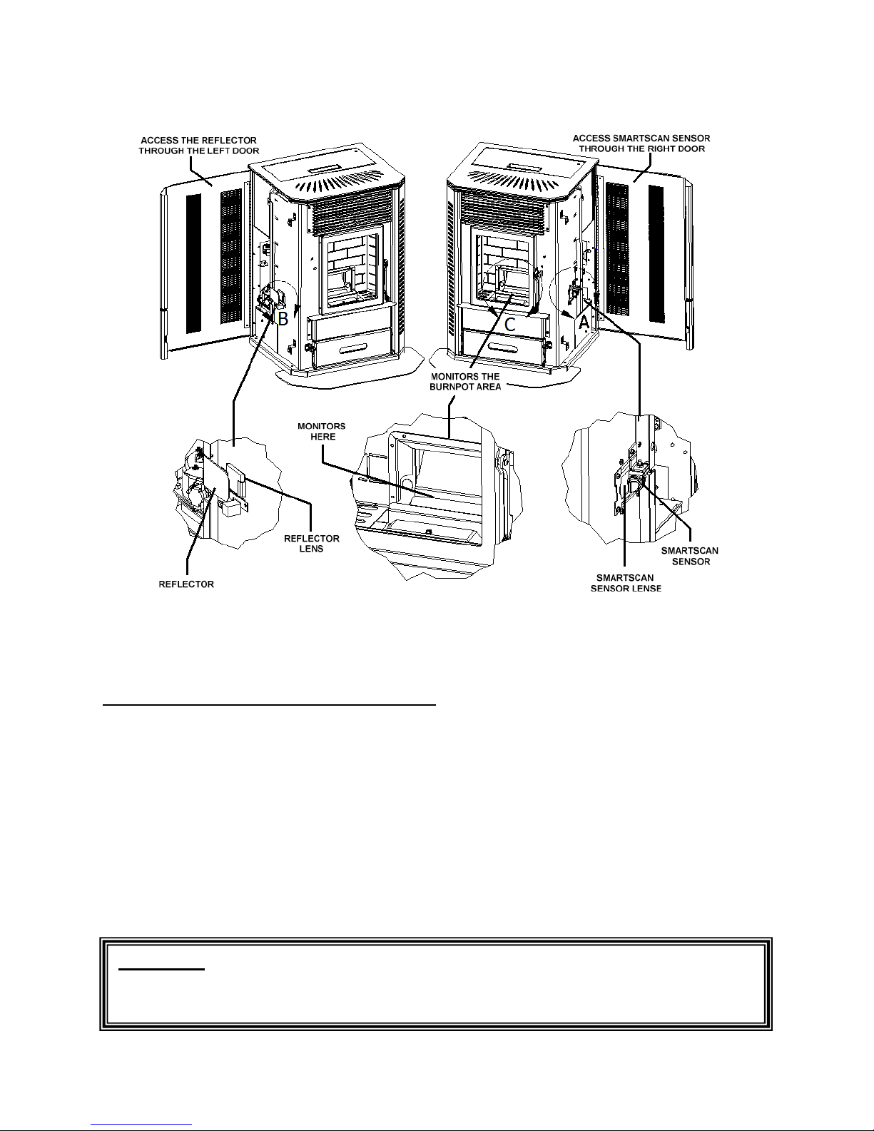
Figure 23
5. Hopper Lid Switch. The hopper lid switch will shut off the auger motor when the hopper lid
is open. Be sure the lid closes completely when refilling the hopper or the unit will shut down.
This switch does not trigger a Diagnostic Code. Do not bypass the Hopper lid Switch.
“Internal Alarm” - When the control board becomes unresponsive, the control board is in
Internal Alarm. The control board has sensed one of the Safety sensors. This may cause the unit
to go out and flash a Diagnostic Code. In some cases, after waiting approximately 45 seconds the
Stove will start responding to the control board again. Many times, the cause of this is a change
in the vacuum inside the firebox. This may be caused by excessive wind or by opening the
Firebox door. The control board will monitor the vacuum switch and resume normal operation if
the vacuum returns to normal.
“Power Reset” - If the board becomes unresponsive for a long period of time, you must unplug
the Stove, wait 10 seconds and plug the unit back in to reset the board.
WARNING: The Stove has been Safety Tested by an accredited, independent
laboratory. These safety features are designed to protect life and property. Bypassing
these features voids all warranties and the safety listing of the Furnace.
Element-MF Installation and Operations Stove
Page 36
Page 37

ELEMENT-MF MAINTENANCE
NOTE: WHEN YOU FIRST OPERATE YOUR ELEMENT-MF, CHECK TO
DETERMINE THE NEEDED CLEANING FREQUENCY. THE ELEMENT-MF
REQUIRES A MINIMUM AMOUNT OF DAILY MAINTENANCE. REQUIRED
MAINTENANCE DEPENDS LARGELY UPON THE QUALITY OF FUEL BURNED
AND THE RATE OF BURN. THE AMOUNT OF DAILY MAINTENANCE WILL
INCREASE IF FUEL QUALITY DECREASES AND/OR THE BURNING RATE OF
THE FUEL INCREASES.
NOTE: FAILURE TO KEEP YOUR STOVE CLEAN, AS DESCRIBED IN THIS
MANUAL, COULD RESULT IN POOR OPERATION, INEFFICIENT FUEL USAGE
AND A POSSIBLE SAFETY HAZARD! IT IS THE RESPONSIBILITY OF THE
OWNER/USER TO DETERMINE THE NEEDED MAINTENANCE FREQUENCY.
CAUTION: THE DOOR AND FRONT PART OF THE STOVE WILL BE HOT. DO NOT
TOUCH ANY PART OF THE UNIT THAT IS HOT!
Clinker/Ash Removal – Element-MF with the Multi-Fuel Pot
Once a clinker/ash has formed in the burn pot, it must be removed or the unit will go out. The St.
Croix Burn system is designed to remove the clinker/ash without losing the fire in the burn pot. It
is a 3-step system.
1. The Coal Rake. This is a “fork” shaped device that will allow the operator to “shave” the
burning coals off the top of the clinker, separating the 2 areas of the burn pot. The
burning fuel on top and the clinker on the bottom.
2. The Slide-Out Bottom. This allows the bottom to be pulled out so the clinker can drop
out of the bottom of the burn pot.
3. The program on the control board. To drop the clinker you set the board to the #1 setting
for a couple of seconds and then return the setting to the desired level. This starts a timed
delay in the program allowing the clinker to be removed, the coals to be dropped to the
bottom of the pot, and the Burn to become balanced again before the board resumes on
the setting of your choice.
Daily Maintenance – Element-MF with the Multi-Fuel Pot
Example Schedule for dropping Clinkers and Ash from burn pot: This may be required
more than once a day, depending on the burn rate of the unit and the quality of Fuel used. Check
your Stove frequently at first to establish a Schedule for cleaning the burnpot. If
Clinker/Ash is not removed, the burnpot will overload and fuel will spill into the Ashpan.
1 - Continuous burning of the Stove on the Low burn setting (Pilot) – Drop the Clinker
approximately every 30-40 hours. This may vary depending on the quality of Fuel used.
2 - Continuous burning of the Stove at the High burn setting (#5) – Drop the Clinker
approximately every 12-18 hours. This may vary depending on the quality of Fuel used.
Element-MF Installation and Operations Stove
Page 37
Page 38
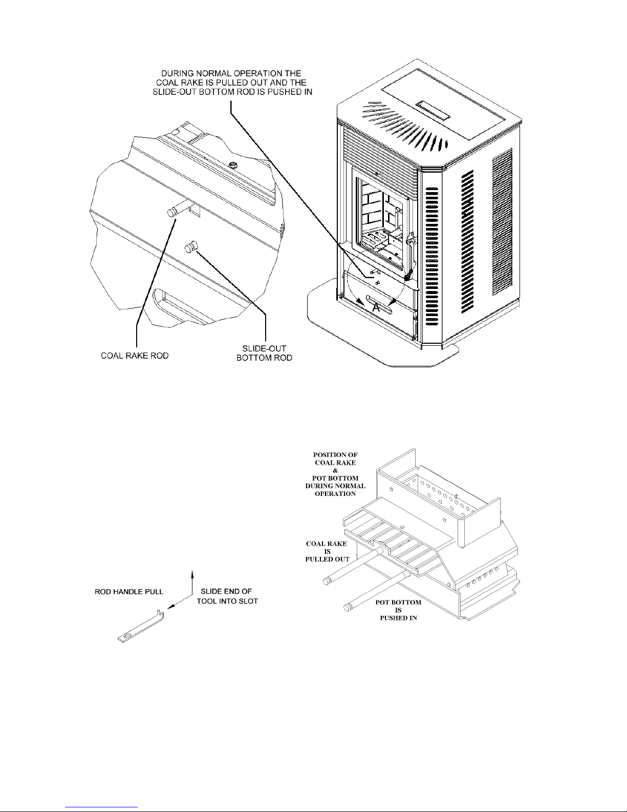
Figure 24
The Daily Maintenance will mainly focus on 4 areas in the Element-MF; removing the clinkers
from the ash pan (if needed), dropping the clinker from the burnpot, cleaning the heat exchange
tubes and cleaning the glass. A breakdown of this process consists of the following steps:
Figure 25
The Coal Rake & the Slide-Out bottom must be in the correct position for the unit to operate correctly.
The Coal Rake must be pulled out or the burn pot will overload.
Element-MF Installation and Operations Stove
Page 38
Page 39
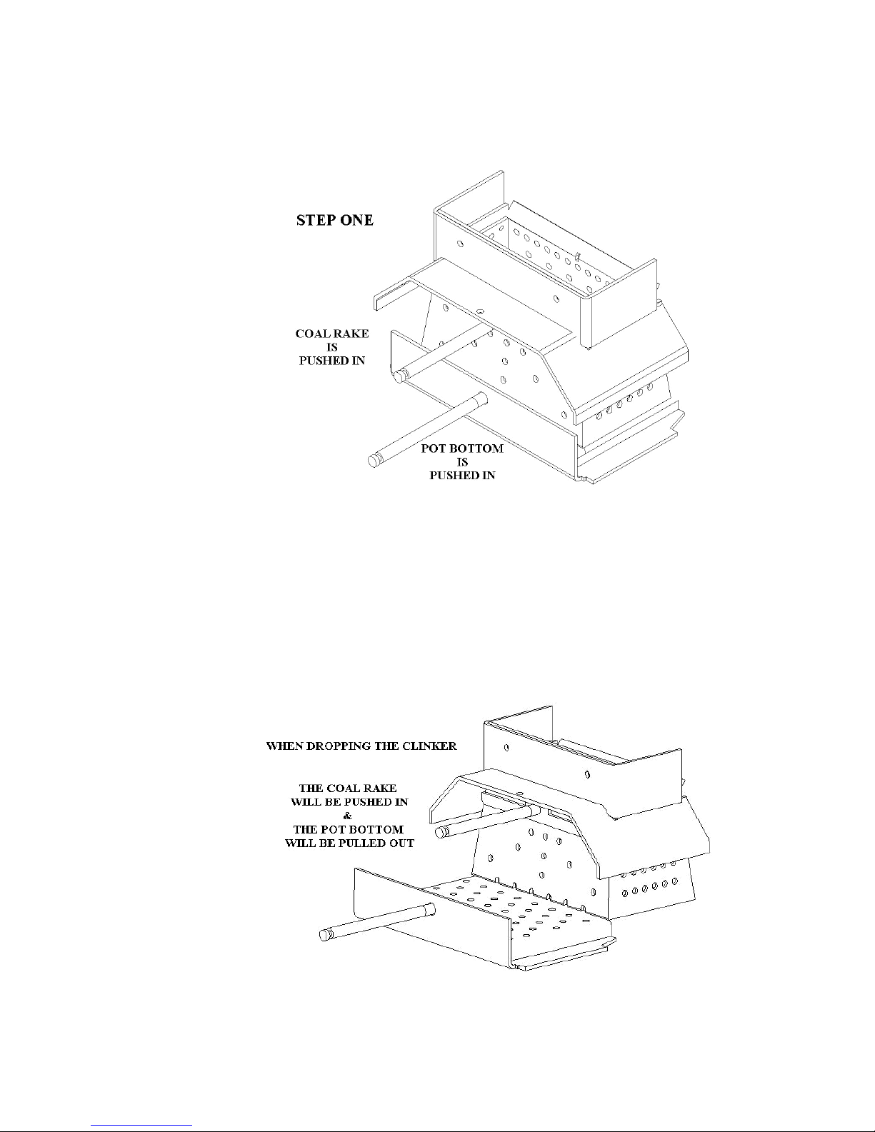
1. The Coal Rake. The first step is to push the coal rake in and separate the coals from the
clinker. Once this is done, open the door and add a ¼ cup of pellets on top of the coals. To
push in the Coal rake, use the Rod Handle tool that came with the unit. (See figure 24 and
25).
Figure 26
2. The Ash Pan. Make sure the Ashpan is not too full to receive a clinker. If the Ashpan is too
full, the clinker may not drop all the way through. This will not allow the Slide-Out Bottom
to be closed. If this happens, empty the Ashpan and restart the unit.
3. The Slide-Out Bottom. (See figure 27) Now you are ready to drop the clinker from the burn
pot. Pull the bottom out in one quick motion and let the clinker drop into the ash pan.
Quickly push the bottom in again. To pull out the slide bottom use the Rod Handle tool that
came with the unit.
Figure 27
Element-MF Installation and Operations Stove
Page 39
Page 40

4. The Control Board. Set the heat setting to #1 for a few seconds and return to the setting it
was on. This initiates the time delay for dropping the clinker.
5. Dropping the coals back into the burn pot. At this time pull the coal rake back out of the burn
pot to drop the coals in the pot. See position of Coal Rake & Pot Bottom in figure 25 on page
38 for normal operation.
The time delay in the program will allow a smooth transition back to where the Stove was
burning before the clinker was dropped.
6. Cleaning the Heat Exchange Tubes. Now you can pull the Tube Scraper back and forth a
couple of times to keep the tubes clean. If the Tube Scraper feels sticky and difficult to move,
check for the presence of creosote on the tubes. If creosote is present a damper adjustment
may be needed or the your Stove has become plugged and needs a thorough cleaning. Call
Dealer for assistance. To pull the tube scraper back and forth use the Rod Handle tool that
comes with your stove.
7. Use a dry paper towel to clean the glass. Quickly open the door and wipe the glass. The rate
of burn will determine how often the window needs cleaning. Prolonged burning at a slow
burn rate will result in the need for more frequent window cleaning. Periodically shut the
Stove down and wipe the window with a cloth or paper towel and glass cleaner. This will
normally keep the window from accumulating difficult to clean residue. Use of a glass
cleaner ONLY permitted when the unit is cold.
CAUTION: Do not slam the door. Do not operate your Stove with a broken or cracked glass.
Replace only with heat resistant ceramic glass supplied by the manufacturer.
There are 2 things to keep an eye on during the cleaning process.
1. If the ash pan door or firebox door were left open for more than 60 seconds the Stove will go
into safety shutdown. Toggle the On/Off switch off and back on. This will reset the board.
You will need to use the auger feed button to manually feed fuel into the pot for a couple of
minutes until the program resumes.
2. If the Element-MF has been running for an extended period of time on the #5 setting, the
clinker will sometimes stick to the burn pot. If that happens, pull the coal rake back out.
Open the door and use a long screwdriver and give the clinker a couple nudges in the pot.
(Make sure the burnpot bottom is closed when you do this or you will lose the coals with the
clinker) Then repeat the steps for dropping the clinker.
Remember: The coal rake must be pulled out and the slide bottom pushed in during normal
operation of the Element-MF.
Remember: The fire door and ash pan doors must be in the latched position during normal
operation of the Element-MF.
Element-MF Installation and Operations Stove
Page 40
Page 41
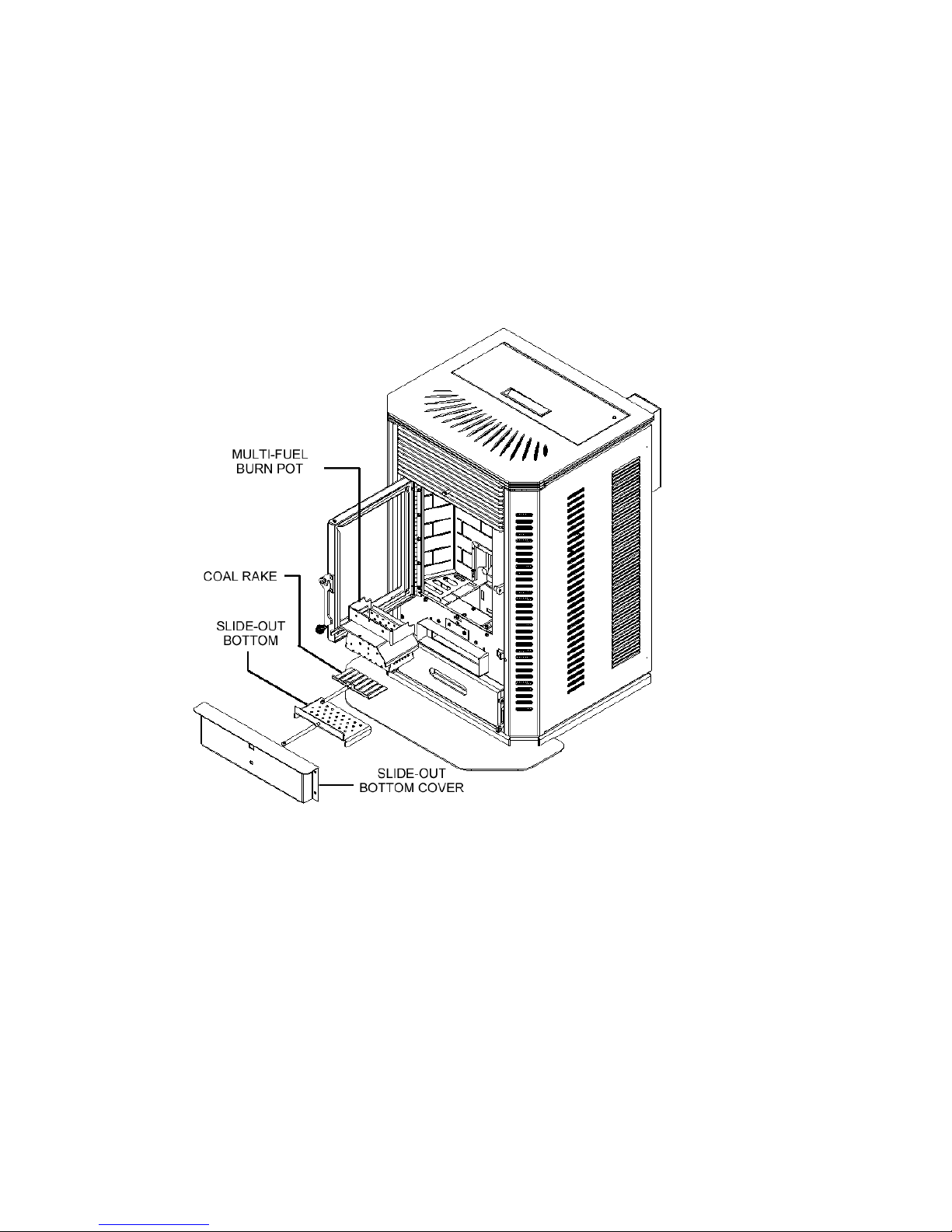
Periodic Maintenance
CAUTION: Periodic maintenance should only be done while the Stove is shut off and cold.
1. Ashpan. Empty the ash pan when it appears full (approximately once a week). The
frequency of cleaning the ash pan will depend on the quality and amount of fuel being used.
Carefully check to make sure the ash pan door is tightly closed after each opening.
2. Burnpot and Slide-Out Bottom. Clean burn grate holes whenever needed. Remove the
Burnpot and use a small metal object (Nail, Drill Bit, etc.) to clean out plugged holes. (See
Figure 28 below).
Figure 28
Burnpot & Slide-out Bottom Removal
To remove the Burnpot from the Stove the Coal Rake must be pulled back so the pot will clear it.
Open the Firebox door of your Stove and you will see 2 Hex head screws. Loosen the first screw
enough to allow the Coal Rake to slide out of the burn pot. Remove the screw that holds the burn
pot in place and lift the pot out of the Stove. To access the Slide-out Bottom, remove the lower
panel and slide the bottom out of the Stove.
3. Clean-Out Ports. The Element-MF has 2 Exhaust Cleanout Ports located in the LEFT AND
RIGHT lower corners of the firebox. Remove covers and clean regularly.
There is an additional Cleanout behind the Ashpan. This cleanout gives access to the
transition area behind the back wall all the way back to below the Combustion Fan. If the
stove seems plugged, this area needs cleaning.
Element-MF Installation and Operations Stove
Page 41
Page 42
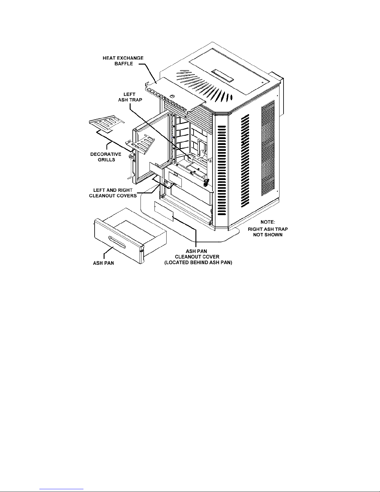
Figure 29
Frequency of cleaning depends on the amount of fuel being burnt and the quality of the Corn,
wheat, rye, Cherry Pits or Distiller’s Grain. Failure to clean the Ash Traps will cause the
Stove to become plugged with Fly Ash.
4. Heat Exchange Baffle. Remove the baffle and clean the ash that accumulates on a
regular basis. Once a month or sooner, depending on the quality of fuel being used
To remove the baffle (See Figure 29), lift the back of the baffle up to clear the inner back of the
stove and slide towards the front of the stove. The baffle will slide out of the keyhole slots and
drop down. When putting the baffle back in the stove, make sure the tabs are in the keyhole
slots and the back of the baffle is lifted up over the inner back.
Clean the baffle on a regular basis. Frequency of cleaning depends on amount of fuel being burnt
and the quality of the fuel. Fuel with low ash content is recommended.
Failure to clean the baffle can cause the Stove to become plugged with fly ash.
5. Exhaust System. See Figure 29 and 30 for information on cleaning fly ash that collects in
the vent system. Periodic cleaning of the exhaust system is required. Under certain conditions
chimneys may plug up rapidly. Dirty/High Moisture content Fuel and poor installations
require more frequent chimney cleanings. The products of combustion will also contain small
Element-MF Installation and Operations Stove
Page 42
Page 43
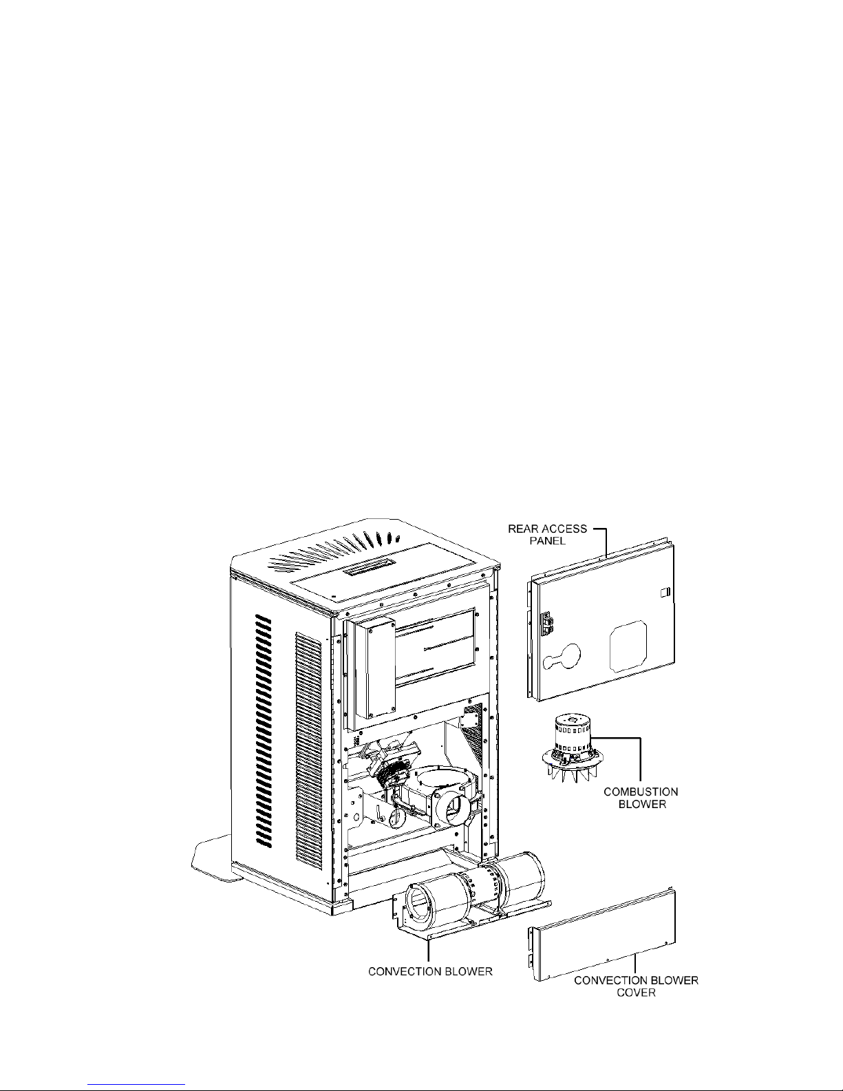
particles of fly ash. The fly ash will collect in the exhaust vent and restrict the flow of the
flue gases.
Judge the frequency of cleaning by checking the amount of ash that accumulates in the
elbows or tee’s of the exhaust system. Ask the dealer for suggested frequency of cleaning,
equipment needed and procedures for cleaning. Check the Exhaust system at least once every
two months during the heating season. See Page 25 “Preventing Chimney Fires”.
6. Gaskets. Periodically inspect the condition of the Rope Gasket around the door, window and
ash door. Replace as needed.
Yearly Maintenance
Many dealers offer a Service Contract that will cover Yearly Maintenance. Contact your St.
Croix Dealer for assistance in maintaining your Element-MF in top condition. Yearly
Maintenance is designed to assure Safe Operation, prolong the life of the Element-MF and help
preserve its aesthetic appeal.
NOTE: UNPLUG THE STOVE. Open the Left and Right side panels of your Element-MF to
gain access to components in the back of the stove. Carefully clean or vacuum any dust, cobwebs
and household dust. Carefully vacuum around the fan motors. If electrical wires become
disconnected call your dealer for service.
Figure 30
Element-MF Installation and Operations Stove
Page 43
Page 44

1. Spring Shutdown. After the last burn in spring let the unit cool down. Remove all fuel from
the Hopper and the Auger. Thoroughly clean the Burn Pot, Burn Pot box, Ash Pan and Ash
Traps behind the ash pan. (To locate the ash traps see figure 29 on page 42)
2. The Exhaust System should be thoroughly cleaned at least annually. Call your dealer for this
service. (See figure 30 on page 43)
3. The Motor/Fan area behind the firebox and under the hopper should be vacuumed annually.
(See figure 30 on page 43)
4. The exhaust fan should be removed and cleaned with compressed air annually. Call dealer
for this service. Annual oiling of the motors is not needed. (See figure 30 on page 43)
5. The Convection fans should be removed and cleaned with compressed air annually. Annual
oiling of the motors is not needed. (See figure 30 on page 43)
6. Replace the Door Gaskets if needed.
7. Replace the Ash Pan Door gaskets if needed.
8. Replace the Hopper Lid Gaskets if needed.
SAFE OPERATION.
Fall Startup. Prior to lighting the first fire check the outside area around the exhaust and air
intake systems for obstructions. Try all controls to see that they are working prior to lighting a
fire.
1. Disposal of Ashes. Ashes should be placed in a metal container with a tight fitting lid. The
closed container of ashes should be placed on a non-combustible floor or on the ground, well
away from all combustible materials, pending final disposal. If the ashes are disposed of by
burial in soil or otherwise locally dispersed, they should be retained in the container until all
cinders have thoroughly cooled.
2. Never use Gasoline, gasoline type lantern fluid. Kerosene, charcoal lighter fluid or similar
liquids to start or “freshen up” a fire in this heater. Keep all such liquids well away from the
heater while it is in use.
3. Creosote, Soot and Fly Ash: Formation and Need for Removal. The products of combustion
will contain small particles of Fly Ash. The fly ash will collect in the venting system and restrict
the flow of flue gases. Incomplete combustion, such as occurs during start-up and shut-down, or
incorrect operation of the room heater will lead to some soot or creosote formation which will
collect in the venting system. The exhaust system should be inspected regularly during the
heating season to determine if creosote buildup has occurred. Check more frequently at first to
determine a schedule for cleaning the venting system based on individual use of this Stove. If
creosote has accumulated, it should be removed to reduce the risk of a chimney fire.
4. Do not Overfire this unit by tampering with the controls on the unit. Follow all
instructions regarding the proper use of this heater.
Element-MF Installation and Operations Stove
Page 44
Page 45
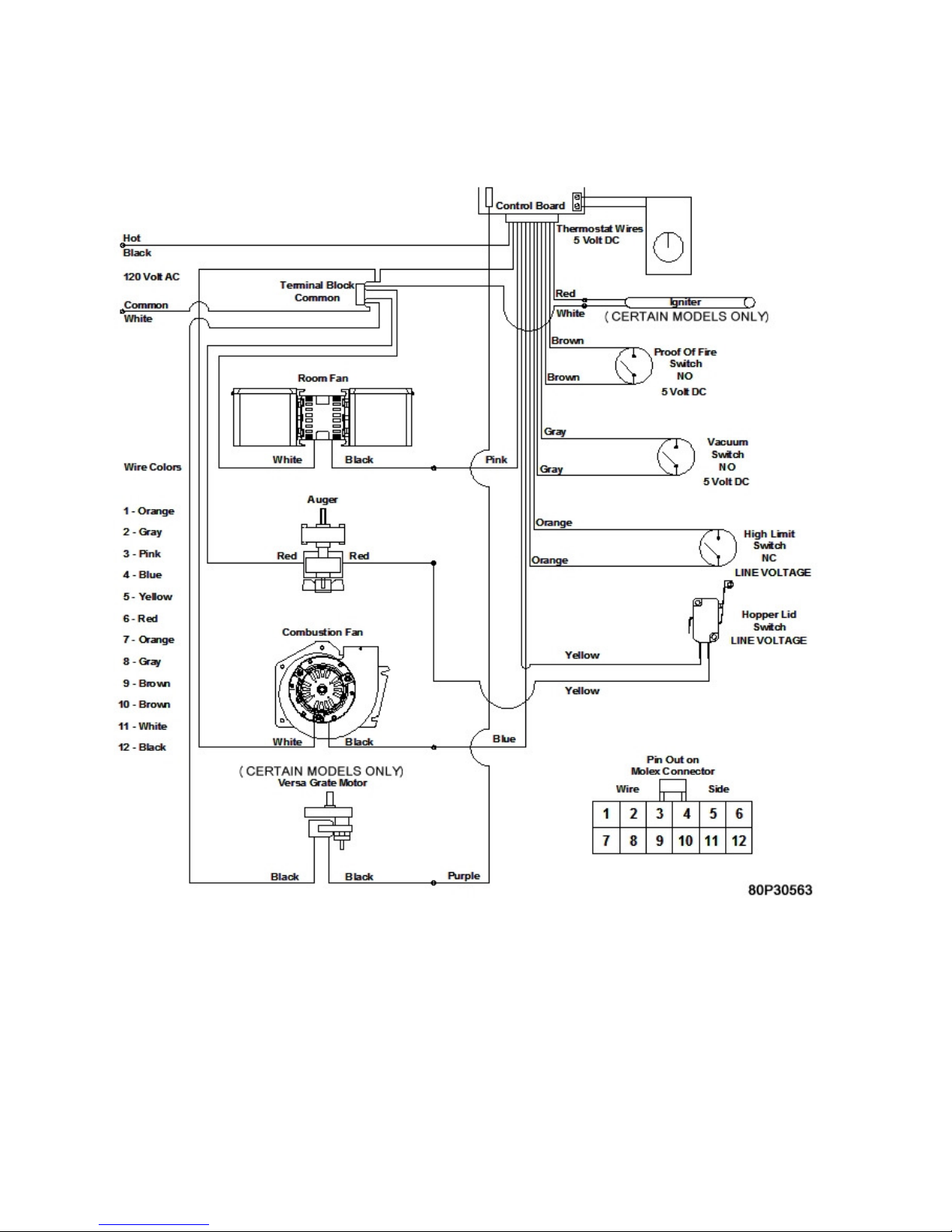
Wiring Schematic
Figure 31
The Electrical Rating of this Stove is: 120 Volt, 60 Hz, 4 Amp with the igniter running and
approximately 2 Amp without the igniter running. The minimum recommended circuit is 15
Amp. A dedicated circuit for the Stove is recommended.
CAUTION: The electrical components of the Element-MF are not owner serviceable. Call your
dealer for proper diagnosis of electrical problems and service to those components.
Element-MF Installation and Operations Stove
Page 45
Page 46

TROUBLESHOOTING & FRQUENTLY ASKED QUESTIONS
The Element-MF is equipped with the Multi-Fuel Burn System.
The Stove is very trouble free in operation when properly maintained and quality fuel is used.
When the Stove fails to operate properly, troubleshooting by the operator of the Stove is limited.
Please read the following guide for answers to frequently asked questions
1. When first starting the Stove, the auger tube is empty, which will delay feeding fuel to the
burn pot. This will in some cases prevent the Stove from starting.
Solution: Prime the burn pot using the Auger Feed button if the auger tube is empty.
2. My Stove keeps overloading the burnpot. First check the moisture content of your fuel. It
should be 15% or less. Also make sure you are using clean fuel. Otherwise this is mainly
caused by improper combustion. (See Damper Adjustment section of the Operations
Manual) Besides the damper adjustment there are several areas that can have an effect on
the combustion process.
Solution: Check all Gaskets, Doors and Door Latching Systems for air leaks. Any leaks in
these areas will negatively affect the burn process and cause the pot to overload.
3. My Stove isn’t burning and the number 2 LED light is blinking. This diagnostic light
indicates the vacuum switch no longer senses negative pressure in the firebox area of the
Stove.
What caused the Stove to go out?
a. The door of the unit was left open longer than 60 seconds. (See solution)
b. The ash pan door was left open for longer than 60 seconds. (See solution)
c. The combustion fan is not running. (Defective fan or control board)
d. The vacuum switch is defective.
e. The vacuum hose is disconnected
f. The vent system is plugged with fly-ash
Solution: If the fire is out, re-light the Stove. If the fire is still burning make sure all doors
are securely latched and hold down the On/Off button (approximately 5 seconds) until Stove
starts up again. This will re-start the Stove in the start-up program.
4. My Stove isn’t burning and the number 3 LED light is blinking. This diagnostic light
indicates that the Proof of Fire Switch no longer senses a fire in the Stove. First check to see
if there is fuel in the hopper. If there is fuel in the hopper, we need to figure out why the
Stove went out.
a. Unburned fuel in the burnpot means the fire went out before the auger quit feeding.
Element-MF Installation and Operations Stove
Page 46
Page 47

Solution: Too much Combustion Air on the pilot setting. Adjust the air damper or the
combustion fan voltage. (See section covering an Unbalanced Burnpot). Fuel would still feed
until the P.O.F. switch eventually shuts the Stove down. (See section covering Damper
Adjustment)
A power failure could also cause this. If the Stove is still hot when the power comes back on, the
feed system will resume. If the fire had gone out in the pot, the feed would continue to run until
the Proof of Fire switch dropped out and shut the Stove down.
b. If all the fuel is burned up means the auger quit feeding fuel while there was still a fire in the
burnpot. Check to see if there is fuel in the hopper. If the hopper is empty, fill the hopper and
re-light the Stove.
If there is fuel in the hopper check to see if there is an obstruction in the auger system or if the
auger set screw is loose.
Solution: Remove obstruction and re-light the Stove or tighten the setscrew on the auger
shaft.
5. My Stove isn’t burning and the #4 LED light is blinking. This means the high Limit has
shut the Stove down. The Convection Blower could be defective or may need cleaning. The
high limit switch may be also defective. It is best to call your dealer for support when trying
to troubleshoot the High Limit Switch. Do not use your Stove if the High Limit switch
frequently trips.
6. I turned the Stove on with the On/Off switch and nothing happens. First check to see if
the Stove is plugged in and the receptacle has power to it.
Solution: Check the fuse on the back of the control board. Replace with a 125 Volt, 5 Amp
fuse.
7. Why is my glass dirty? Normal operation of your St. Croix Stove will produce a
light build-up on the glass that wipes off with a dry paper towel. However extended burning
on the low setting only will produce a tan color. These types of build-up on the glass are
normal. A heavy black build-up on the glass could indicate a problem.
Solution: Adjust the combustion air damper or combustion fan voltage. If this doesn’t seem
to help, make sure the clean out cover plates are installed in the Stove. It also could be an
indication that the Stove is getting plugged and needs a good cleaning. Refer to the section in the
manual that covers the Daily, Periodic and Yearly Maintenance of the Stove.
Element-MF Installation and Operations Stove
Page 47
Page 48
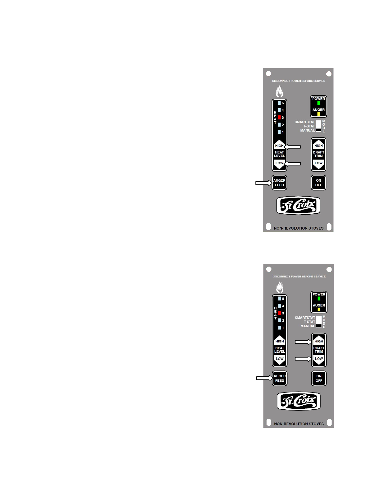
8. Are there any adjustments that can be made, through the control board, to the amount
of fuel that is fed into the burnpot?
Answer: There are several ways to adjust the amount of fuel that
is fed into the burnpot. The Feed Rates can be fine-tuned while
the Stove is in operation by pressing and holding the “Auger
Feed” button down and then either pressing the “Heat Level
High” button to advance the feedrate higher, or pressing the
“Heat Level Low” button to decrease the feedrate.
There are 5 levels on the control board and they are indicated by
a single flash of the LED’s. The default setting is the center
LED. This gives 2 adjustments increasing the Feed Rate (LED’s
4 & 5) and 2 adjustments decreasing the Feed Rates. (LED’s 1 &
2) The ON time is increased or decreased .25 seconds with each
adjustment.
Figure 32
9. Are there any adjustments that can be made, through the control board, to the
Combustion Fan voltages to help adjust the draft?
Answer: The Draft can be adjusted in a similar fashion as
mentioned in the previous example.
The Fan voltages can be fine-tuned while the Stove is in
operation by pressing and holding the “Auger Feed” button
down and then either pressing the “Trim High” button to
advance the voltages higher, or pressing the “Trim Low” button
to decrease the fan voltages.
There are 5 levels on the control board and they are indicated by
single flash of the LED’s. The default setting is the center LED.
This gives 2 adjustments increasing the voltage (LED’s 4 & 5)
and 2 adjustments decreasing the voltage. (LED’s 1 & 2) The
voltage is increased or decreased 2.5 volts with each adjustment.
Figure 33
Element-MF Installation and Operations Stove
Page 48
Page 49
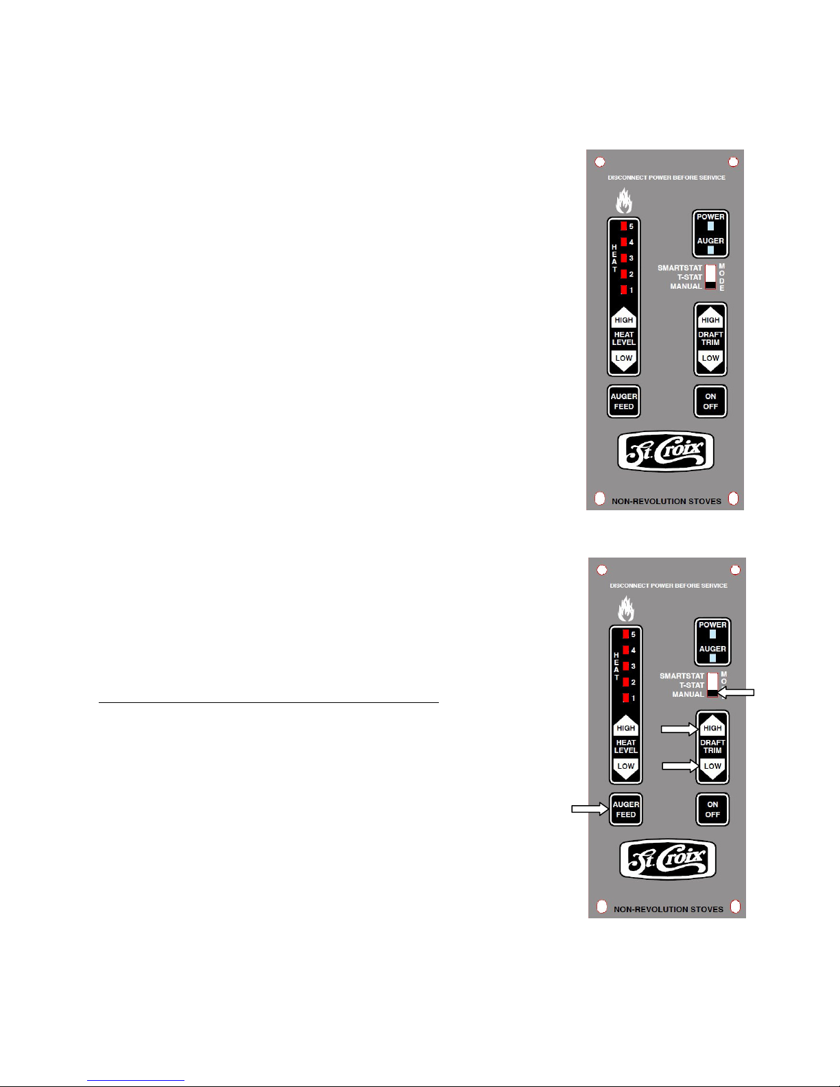
10. Are there Cycle Time adjustments on the Control Board for different types of fuel?
Answer: There are 4 individual programs on the control board,
each with a different Cycle time.
The Control board has been factory set to the default Program for
your Model. When reprogramming the control board, you will
see LED light flash, as shown in the figure to the right. The LED
lights flash in the following manner:
Program 1 – 11.5 second cycle time. The LED’s flash once.
This program is for use with Corn, Wheat, Rye, Cherry Pits or
Distiller Grain. (When using this program with Wheat or Rye, the
ON-Times may need to be decreased. See point 8 on page 47).
This program is for use with the Element-MF
Program 2 – 13.0 second cycle time. The LED’s flash twice.
This program is for use with Corn, Wheat, Rye, Cherry Pits or
Distiller Grain. This program is for use with the Element-MF
Program 3 - 11.5 second cycle time. The LED’s flash three
times. This program is for use with Pellets. This program has
Self-Ignition and is used in units that have the Versa Grate
System & Igniter installed. This program is not for use with the
Figure 34
Element-MF.
Program 4 – 10.0 second cycle time. The LED’s flash four
times. This program has Self-Ignition and is used in units that
have the Versa Grate System & Igniter installed. This program is
not for use with the Element-MF.
11. How do I change to a different Program on the control board?
First the Stove must be turned off and cooled down.
Step 1 - The Thermostat switch must be in the Manual position.
Step 2 – Press and hold the Auger Feed Button.
Step 3 – Press the Trim High and Low Buttons at the same time.
Release all 3 buttons immediately.
Step 4 – Observe the LED light flashing according to the Program
chosen. Program 1 flashes once, Program 2 flashes twice, Program
3 flashes three times and Program 4 flashes 4 times.
Changing the Cycle Time will change the BTU Input of the Stove.
The longer the Cycle time the lower the BTU rating.
Figure 35
Element-MF Installation and Operations Stove
Page 49
Page 50
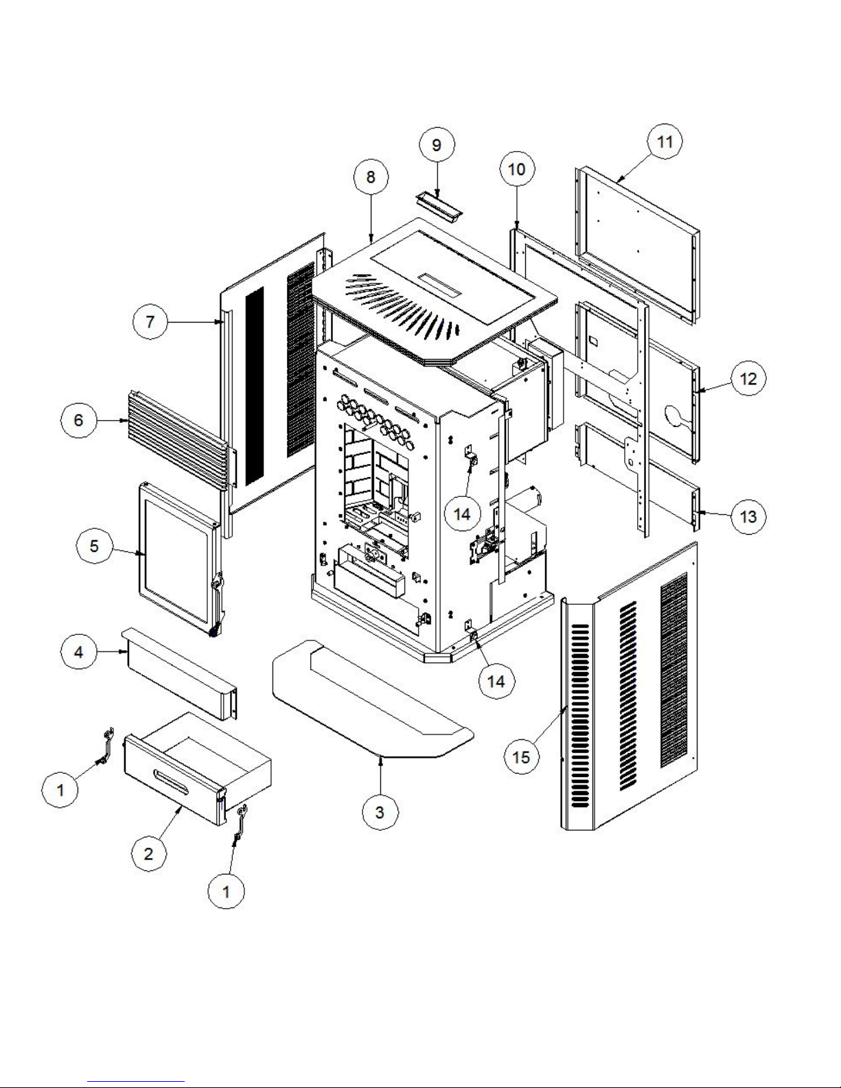
Element-MF Parts
Figure 36
Element-MF Installation and Operations Stove
Page 50
Page 51
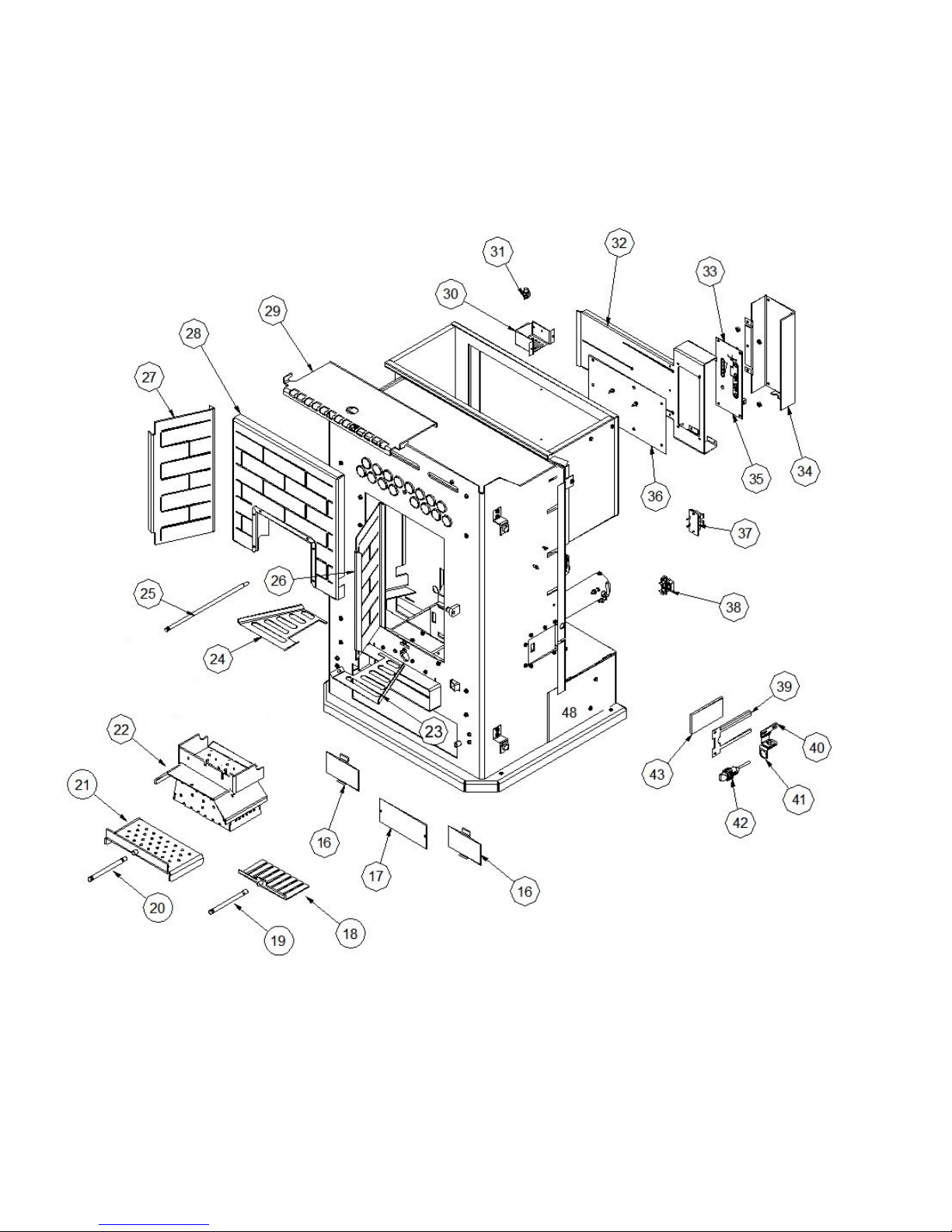
Element-MF Parts
Figure 37
Element-MF Installation and Operations Stove
Page 51
Page 52
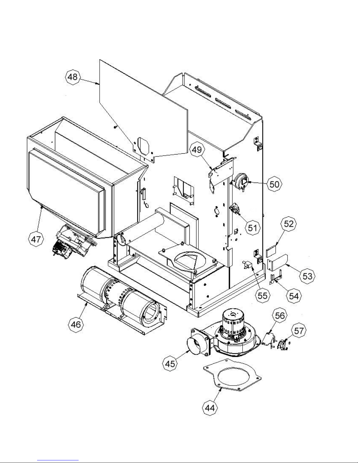
Element-MF Parts
Figure 38
Element-MF Installation and Operations Stove
Page 52
Page 53
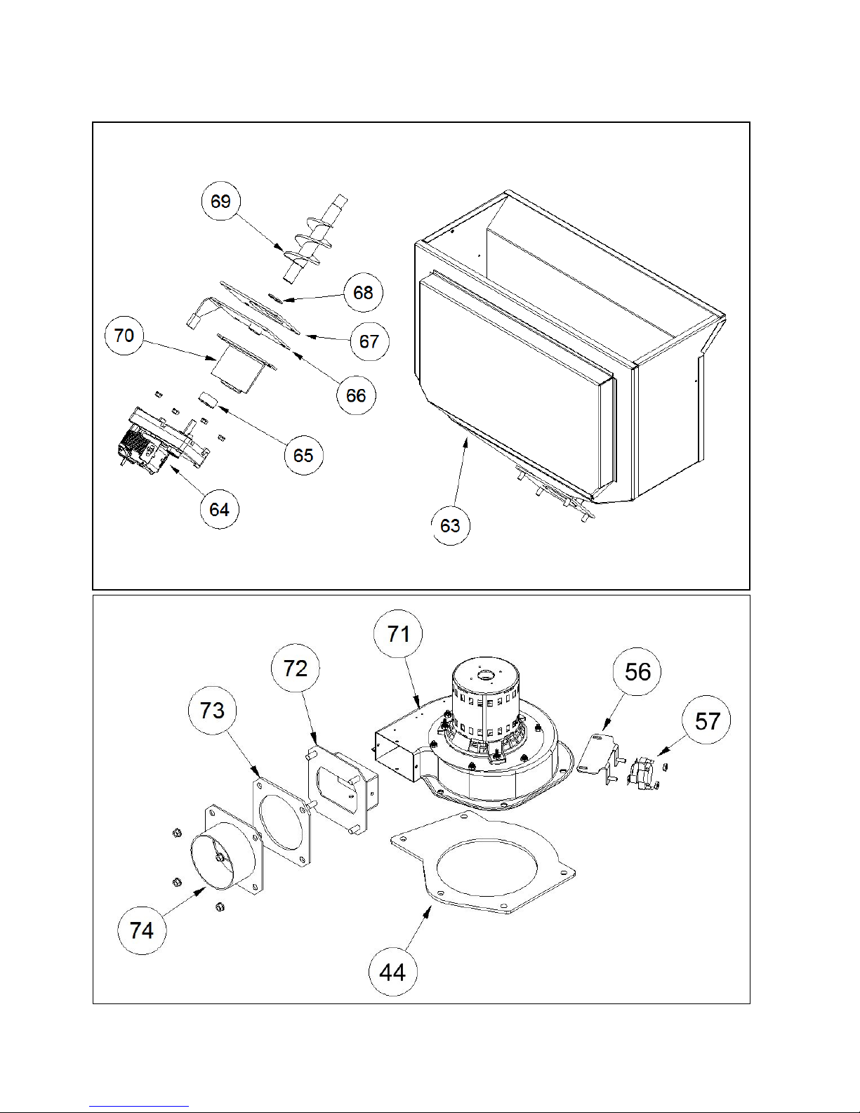
Element-MF Parts
Figure 39
Figure 40
Element-MF Installation and Operations Stove
Page 53
Page 54
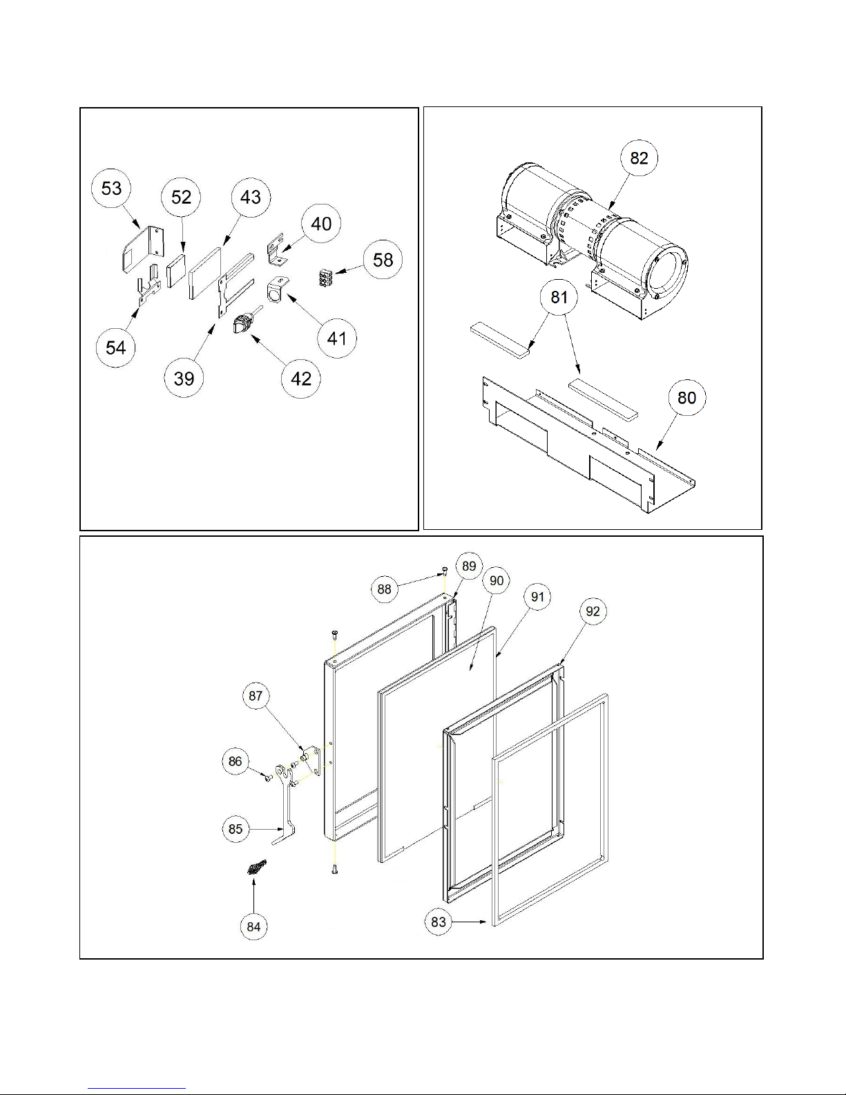
Sensor System Figure 41
Element-MF Parts
Figure 42
Element-MF Installation and Operations Stove
Figure 43
Page 54
Page 55
# PART NUMBER DESCRIPTION
1 80P31008-R ASH DOOR HANDLE
2 80P54243-R ASHPAN WELDMENT
3 80P54220-R SPARK ARRESTOR PAD
4 80P54185-R ASHLIP WELDMENT
5 80P52948-R DOOR ASSEMBLY - COMPLETE
6 80P54221-R LOUVER BOX WELDMENT
7 80P54186-R LEFT SIDE DOOR-WELDMENT
8 80P54164-R TOP WELDMENT
9 80P20183-R HANDLE PULL P2-54 FOR HOPPER LID
10 80P30903-R BACK PANEL
11 80P30973-R REAR HOPPER COVER
12 80P30970-R BACK PANEL COVER
13 80P30042-R BLOWER COVER
14 80P54223-R DOOR MAGNET ASSEMBLY
15 80P54187-R RIGHT SIDE DOOR WELDMENT
16 80P52237-R CLEANOUT COVER PLATE
17 80P30280-R ASHPAN CLEANOUT COVER
18 80P53619-R COAL RAKE WELDMENT
19 80P52568-R COAL RAKE ROD
20 80P52627-R POT SLIDER ROD
21 80P54184-R POT SLIDER WELDMENT
22 80P54183-R MULTI-FUEL POT WELDMENT
23 80P30927-R DECORATIVE GRILL - RIGHT
24 80P30926-R DECORATIVE GRILL - LEFT
25 80P52567-R TUBE SCRAPER ROD
26 80P30924-R BRICK RIGHT SIDE PANEL
27 80P30923-R BRICK LEFT SIDE PANEL
28 80P54181-R STEEL BRICK - BACK PANEL
29 80P52366-R HEAT EXCHANGE BAFFLE
30 80P30697-R HOPPER LID SWITCH BOX
31 80P31003-R HOPPER LID SWITCH
32 80P53785-R CONTROL BOARD BOX WITH CLINCH STUDS
33 80P30523B-R CONTROL BOARD
34 80P52658-R CONTROL BOARD HARNESS RESTRAINT
35
NOT USED NOT USED
36 80P53681-R SLIDE-TOP STANDOFF PLATE ASSEMBLY
37 80P30045-R SPEAKER TERMINAL
38 80P52630-R TERMINAL BLOCK
39 80P30809-R GLASS RETAINER
40 80P30807-R RIGHT ANGLE SENSOR BRACKET
41 80P54205-R ADJUSTABLE SENSOR BRACKET ASSEMBLY
42 80P30948-R PHOTOELECTRIC SENSOR
Element-MF Installation and Operations Stove
Page 55
Page 56
#
19.5”
PART NUMBER DESCRIPTION
43 80P30962-R SENSOR GLASS
44 80P20168-R COMBUSTION FAN GASKET
45 80P54216-R COMBUSTION FAN ASSEMBLY
46 80P52949-R CONVECTION FAN ASSEMBLY
47 80P54281-R HOPPER ASSEMBLY
48 80P60489-R HOPPER MOUNT GASKET
49 80P30989-R VACUUM SWITCH MOUNTING BRACKET
50 80P30658-R VACUUM SWITCH
51 80P52629-R MANUAL RESET HIGH LIMIT DISC
52 80P30810-R SENSOR GLASS
53 80P54188-R SENSOR REFLECTOR PLATE ASSEMBLY
54 80P30808-R GLASS RETAINER - BENT
55 80P52634-R BARB FITTING
56 80P54217-R P.O.F. SWITCH BRACKET ASSEMBLY
57 80P20038-R PROOF OF FIRE DISC
58 80P30992-R PLASTIC TERMINAL BLOCK
59
60
61
62
NOT USED NOT USED
NOT USED NOT USED
NOT USED NOT USED
NOT USED NOT USED
63 80P54280-R HOPPER WELDMENT
64 80P20278-R AUGER MOTOR
65 80P20248-R 5/8" COLLAR WITH SETSCREW
66 80P54074-R MOTOR MOUNT BRACKET AND END CAP
67 80P20245-R AUGER GASKET
68 80P50858-R AUGER BUSHING WASHER
69 80P52956-R AUGER WELDMENT
70 80P30191-R MOTOR RETAINER BRACKET
71 80P30521-R COMBUSTION FAN
72 80P52889-R EXHAUST ADAPTER PLATE ASSEMBLY
73 80P52232-R QUICK DISCONNECT GASKET
74 80P52887-R QUICK CONNECT PIPE WELDMENT
75
76
77
78
79
NOT USED NOT USED
NOT USED NOT USED
NOT USED NOT USED
NOT USED NOT USED
NOT USED NOT USED
80 80P52437-R CONVECTION FAN MOUNT BRACKET
81 8709K46 1/4" x 1" FOAM TAPE –
82 80P20003-R CONVECTION FAN
83 80P20132-R DOOR GASKET – 48”
84 80P20131-R SMALL BRASS COIL
85 80P53773-R DOOR HANDLE - PAINTED
Element-MF Installation and Operations Stove
Page 56
Page 57
#
PART NUMBER DESCRIPTION
86 10-24X3-8BSHCS 10 - 24 X 3/8" BUTTON SOCKET CAP SCREW
87 80P53677-R MOUNT PLATE ASSEMBLY
88 8X1/2HWHTEK-B #8 X 1/2" HWH TEK SCREW - BLACK
89 80P52947-R DOOR WELDMENT
90 80P52375-R DOOR GLASS
91 80P20022-R GLASS GASKET – 44”
92 80P52357-R GLASS RETAINER
Element-MF Installation and Operations Stove
Page 57
Page 58

ELEMENT-MF WARRANTY
The Stove manufactured by Even Temp, Inc. is warranted for five (5) years, to the original owner, against
defects and workmanship on all steel parts (excluding the burn grate, Baffle and Brick Panels) and two (2)
year on electrical components from the date of sale to the original owner. There specifically is no
warranty on the paint, glass and all gaskets. There is no written or implied performance warranty on the
Stove, as the manufacturer has no control over the installation, daily operations, maintenance or the type
of fuel burned.
This warranty will not apply if the Stove has not been installed, operated and maintained in strict
accordance with the manufacturer's instructions. Burning other than approved quality fuels may cause
Stove damage and could void the warranty.
The warranty does not cover damage or breakage due to misuse, improper handling or modifications.
A warranty registration card is provided. The card is to be checked and signed and returned to factory by
the owner. Appropriate information is to be noted on the card.
All claims under this warranty must be made through the dealer where the Stove was purchased. If an
inspection by the dealer indicates that a warranty claim is justified, and that all conditions of this warranty
have been met, the manufacturer's total responsibilities and liabilities shall be to repair or replace, at the
manufacturer's option, the defective part(s). All costs of removal, shipment to and from the dealer or
manufacturer, any losses during shipment and reinstallation and any other losses due to the Stove being
removed shall be covered by the owner of the Stove.
NEITHER THE MANUFACTURER, NOR THE SUPPLIERS TO THE PURCHASER, ACCEPTS
RESPONSIBILITY, LEGAL OR OTHERWISE, FOR THE INCIDENTAL OR CONSEQUENTIAL
DAMAGE TO PROPERTY OR PERSONS RESULTING FROM THE USE OF THIS PRODUCT. ANY
WARRANTY IMPLIED BY LAW, INCLUDING BUT NOT LIMITED TO IMPLIED WARRANTIES
OF MERCHANTABILITY OR FITNESS, SHALL BE LIMITED TO ONE (1) YEAR FROM THE
DATE OF ORIGINAL PURCHASE. WHEN A CLAIM IS MADE AGAINST THE MANUFACTURER
BASED ON THE BREACH OF THIS WARRANTY OR ANY OTHER TYPE OF WARRANTY
EXPRESSED OR IMPLIED BY LAW, MANUFACTURER SHALL IN NO EVENT BE LIABLE FOR
ANY SPECIAL, INDIRECT, CONSEQUENTIAL OR OTHER DAMAGES OF ANY NATURE
WHATSOEVER IN EXCESS OF THE ORIGINAL PURCHASE PRICE OF THIS PRODUCT. ALL
WARRANTIES BY MANUFACTURER ARE SET FORTH HEREIN AND NO CLAIM SHALL BE
MADE AGAINST MANUFACTURER ON ANY ORAL WARRANTY OR REPRESENTATION.
Some states do not allow the exclusion or limitation of incidental or consequential damages, or limitations
of implied warranties; therefore the limitations of exclusions set forth in this warranty may not apply to
you. This warranty gives you specific legal rights, and you may have other rights, which vary from state
to state.
Element-MF Installation and Operations Stove
Page 58
Page 59

Notes:
After the break in period, please note any adjustments that were made to the Feed Trim and
Draft Trim on the control board in the area below.
Feed Trim: Circle one (See point 2 on page 27)
LED #1 LED #2 LED #3 LED #4 LED #5
Draft Trim: Circle one (See point 4 on page 27)
LED #1 LED #2 LED #3 LED #4 LED #5
APPROVED FUEL: Circle One
CORN WHEAT RYE CHERRY PITS DISTILLERS GRAIN
PROGRAM: Circle one (see Figure 19 on page 28)
1 2
Serial Number:
Date of Purchase:
Dealer Information:
WEB ADDRESS: www.stcroixstoves.com
Element-MF Installation and Operations Stove
EMAIL: [email protected]
Page 59
 Loading...