

Page 1
™
®
DIRECT FIELD MONITOR SYSTEM
20/20 V2
Page 2

Thank you for choosing the 20/20™ V2 Direct Field Monitor System. To get the
most from your new monitors, please take a moment to read this manual and
familiarize yourself with the product’s features, set-up, and use.
About the 20/20 Series
Our engineers have spent years designing transducers, studio electronics, and high
performance studio monitoring systems—including some of the most popular
professional speakers used today. Now, using the latest digital acoustic design tools
and high performance driver and power amplifier technology, they’ve developed
the 20/20 V2 series—the successor generation to our award-winning 20/20
™
and
20/20bas
™
monitors. The V2 monitors feature a number of technical improvements,
while at the same time maintaining the standards in performance and sonic
excellence for which the original 20/20 series is internationally renowned.
The 20/20 V2 series comprises two 8" two-way models, the passive 20/20 V2 and
the active 20/20bas V2. Both models incorporate the same 1" silk dome high
frequency driver and 8" mineral impregnated low frequency driver used in the
original 20/20 and 20/20bas, so the accuracy and frequency response of the V2
models is virtually identical to the originals. The components are housed, however
in a new cabinet that features updated styling—and, more importantly—additional
protection against accidental damage. The 20/20bas V2 also features an advanced
new amplifier that delivers enhanced performance. Theamplifier is powered by a
toroidal transformer, for greatly reduced mechanical and electrical noise.
Unpacking
The monitors’ shipping container and inner boxes are designed to pr otect them
during transit. Please unpack and check your monitors carefully, and immediately
report any damage to your dealer or to the company that delivered them to you.
The packing materials are designed to be reused—do not discard them. If you
need to retur n the monitors to the factory for r epair, they must be shipped in
the original packaging.
Setup
You’ll notice that the 20/20 V2 monitors are physically identical. When used
in a stereo configuration, there is no physical or acoustic distinction between
the left and right speakers. The cabinets can sit ver tically or horizontally so
long as both cabinets are situated in the same direction. To maximize the
“sweet spot” we recommend that the cabinets be oriented ver tically. If you
choose to place them in a horizontal position, orient the cabinets with the high
frequency drivers pointing to the outside, away from each other. Since each
2
20/20 V2 User Guide
Page 3
cabinet’s bass por t is front-mounted, you can position the monitors near a wall
(or even in a wall) without fear of blocking the por t, which would compr omise
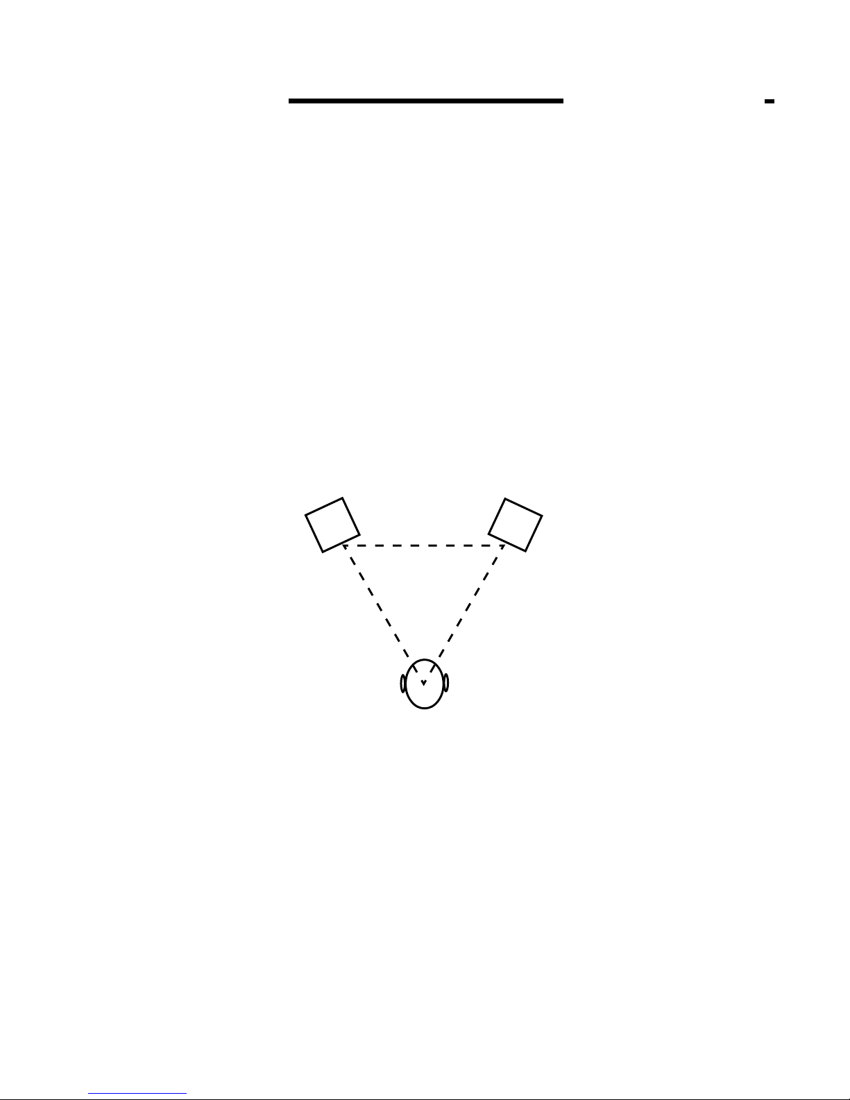
the bass response. Notice that Figure 1 also shows the speaker cabinets turned
slightly inward, so that the driver components directly face the listening position.
When oriented this way, the listener is in the “sweet spot,” which yields the most
accurate stereo reproduction. If you need a wider sweet spot to allow for greater
listener movement or for group monitoring, face the speakers in a slightly more
open position, but never more than necessary. Finally, if you must mount the
speakers substantially above or below ear level, you will also need to tilt the
cabinets downward or upward to keep the driver components directly facing you.
As you become more familiar with your speakers, you may find it helpful to
move around in the soundfield to locate the optimum listening position for your
particular monitoring environment. But if you follow the equal-distance, ear-level,
face-on r ules outlined above, you’ve alr eady optimized their position for a single
user in most situations.
Figure 1. When the listener and the monitors are positioned in an
equal triangle with the monitors directly facing the listener, the listener is
situated in the “sweet spot,” which yields optimum stereo reproduction.
3
Connecting the Passive 20/20 V2 Speakers to an External Amplifier
The passive 20/20 V2 monitors present a 4 ohm nominal load impedance to the
amplifier. Amplifiers rated for 8 ohm minimum loads are generally not suitable and
may even suffer damage if used. We recommend using a power amplifier rated in
the range of 100 – 200 watts per channel into 4 ohms. Higher power amplifiers can
be used with caution, but care must be taken to never exceed the 20/20 V2’s 150W
program/200W peak ratings. Event is not responsible for damage caused by
overpowering the speaker’s components.
20/20 V2 User Guide
Page 4

Connections to the monitors are made via the five-way binding posts on the
monitors’ rear panels. These terminals will accept large diameter bare or tinned
wires, spade or pin terminals, or banana plugs. Use the shortest length of #10 – #14
guage speaker wire to connect the positive (red) and negative (black) speaker
terminals to the similarly marked terminals on your power amplifier. Watch for
accidental polarity reversal (it happens!), as this will cause a loss of low frequency
response and center image.
Connections and Operation: Active 20/20
bas
V2
1 Input Sensitivity This control is used to compensate for different signal
levels that appear at the input. The control has a 20dB range; when set at maximum
(MAX), 1.1V RMS input at the balanced ins will produce full amplifier output.
Note that when the signal appearing at the input is too hot, the amplifiers may
overload, causing distortion. If this occurs, attenuate (decrease) the Input
Sensitivity by turning the control counter-clockwise.
2 High Frequency Trim Control This control can be used to tailor the high
frequency response of the system to your room. Turn the control clockwise to
increase the high frequency response; counter-clockwise to decrease it. The center
detent indicates the control’s “flat” position.
3 Input 1 This balanced 1/4" line input jack accepts a male two-conductor
1/4" TS or three-conductor 1/4" TRS connector, wired for either balanced or
unbalanced operation. For unbalanced operation with a TS connector, the minus
signal is automatically grounded; with a TRS connector you have the option of leaving
the minus input open or grounded. We recommend, however, that you ground the
unused input. For balanced operation, which requires using a TRS connector, please
consult the pin wiring diagram on the monitor’s back panel.
Note: Inputs 1 and 2 are hardwired in parallel, so either may be used as an input or
as a pass-through connection. Input specifications apply equally to both inputs.
4 Input 2 This balanced XLR line input accepts a male XLR connector, wired
for either balanced or unbalanced operation. For balanced operation, please consult
the pin wiring diagram on the monitor’s back panel.
5 Low Frequency Trim Control This control can be used to tailor the low
frequency response of the system to your room. Turn the control clockwise to
increase the low frequency response; counter-clockwise to decrease it. The center
detent indicates the control’s “flat” position.
4
20/20 V2 User Guide
Page 5

6 Power Switch Push the left side of the switch to turn the amplifiers on ( | );
push the right side of the switch to turn them off. When the amplifiers are on, the
green LED located in the metal trim ring on the front of the monitor will illuminate.
7 Power Connector This connector accepts the detachable AC line cord. Use
the line cord supplied with your monitor, and make sure it is fully seated into the
Power Inlet connector. For safety reasons, do not attempt to defeat the line cord’s
ground connection.
5
1
5
4
3
7
2
20/20 V2 User Guide
6
Page 6

Care and Maintenance
Your 20/20 V2 monitors are simple to care for and maintain. The cabinets are
finished with a durable vinyl laminate that can be cleaned with a soft damp cloth.
Avoid touching the exposed speaker elements. Do not expose the rear panel
controls, connectors, or the speaker elements to moisture or chemicals. Do not
expose the unit to dripping or splashing liquids; objects filled with liquids should
not be placed on the unit.
Caution (20/20bas V2 only): When the power switch is off, the internal amplifier
components are still connected to the AC mains. The AC mains fuse is internal and
serviceable by a qualified technician; it will only open if there is another problem.
Please refer service to qualified personnel.
Mix at reasonable levels to protect your speakers and your hearing.
Contacting Customer Service
If you experience any trouble with your 20/20 V2 monitors, please call the Event
Electronics Customer Service department at 805-566-7777, ext. 5. Before calling,
however, we ask that you please consult the Technical Support section of our Web
site,
www.event1.com.
If you believe your 20/20 V2 monitor is in need of repair, please contact the Event
Electronics Customer Service department to request a Return Authorization
Number (RA#). We can accept for servicing only those units that are
accompanied by an RA#. Units shipped without an RA# number will be refused.
20/20 V2 Specifications
Low Frequency Driver
8" magnetically shielded mineral-impregnated polypropylene cone with high temperature
voice coil and damped r ubber surround.
High Frequency Driver
1" magnetically shielded natural silk dome neodymium with ferrofluid-cooled voice coil.
Frequency Response
50Hz – 20kHz, ±3dB, Ref 500Hz
Crossover
2.2kHz, second-order
Power Handling:
150W program; 200W peak
6
20/20 V2 User Guide
Page 7

20/20 V2 Specifications (cont.)
Nominal Input Impedance
4 ohms
Input Sensitivity
88dB @ 1W/1m
Cabinet
1/2" vinyl-laminated MDF, internally insulated
Connectors
Red and black five-way binding posts on 3/4" centers
Polarity
Positive signal at red terminal produces outward low frequency cone displacement
Dimensions
10.25" W x 14.75" H x 11.75” D
Weight
21 lbs each
20/20
bas
V2 Specifications
Low Frequency Driver
8" magnetically shielded mineral-impregnated polypropylene cone with high temperature
voice coil and damped r ubber surround.
High Frequency Driver
1" magnetically shielded natural silk dome neodymium with ferrofluid-cooled voice coil.
Frequency Response
38Hz – 20kHz, ±3dB, Ref 500Hz
Low Frequency Amplifier Power
130W program
High Frequency Amplifier Power
70W program
Input Connectors
XLR and 1/4" connectors; accept balanced or unbalanced sources
Polarity
Positive signal at + input produces outward low frequency cone displacement
Crossover
2.6kHz, active fourth-order asymmetrical
720/20 V2 User Guide
Page 8

20/20bas V2 Specifications (cont.)
Power RequirementsInput Impedance
40kΩ (balanced)
Input Sensitivity
1.1V input produces full output with Input Level Control at maximum
Input Sensitivity Control Range
20dB
Low Frequency Trim
Continuously variable control calculated in 1dB incremements; Max boost/cut settings
produce ±3dB @ 100Hz, ±2dB @ 400Hz
HighFrequency Trim
Continuously variable control calculated in 1dB incremements; Max boost/cut settings
produce ±3dB above 2.6kHz
Indicators
Power ON/Clip LED
Protection
RF interference, output current limiting, over temperature, turn on/off transient, subsonic
filter, internal mains circuit fuse
Power Requirements
200VA, factory programmed for either 120V~ 60Hz, 220-240V~ 50-60Hz, or
100V~ 50-60Hz mains
Cabinet
1/2" vinyl-laminated MDF, internally insulated
Dimensions
10.25" W x 14.75" H x 11.75” D
Weight
29 lbs each
Specifications subject to change without notice.
©2003 Event Electronics, LLC
P.O. Box 4189
Santa Barbara, CA 93140-4189
www.eventelectronics.com
Event Electronics
®
is a registered trademark of Event Electronics, LLC.
20/20 and 20/20bas are trademarks of Event Electronics, LLC.
8
2412
20/20 V2 User Guide
 Loading...