

Page 1
OMNI.EVELO.COM
Installation, Use & Safety Information
Page 2
TABLE OF CONTENTS
1. Warnings
2. Installation
2.1 Parts List
2.2 Accessories
2.3 Removal of Front Wheel
2.4 Installation of Omni Wheel
2.5 PAS Speed Sensor Installation
2.6 Installation of Console
2.7 Installation of Brake Levers (optional)
2.8 Turning on the Omni Wheel
3. Console Operating Instructions
3.1 Data Readouts
3.2 Additional Console Functionality
4. Charging
4.1 Charging the Console
4.2 Charging the EVELO Omni Wheel
4.2 Charger LED Color Chart
5. Maintenance & Repair
4
6
7
8
9
9
12
13
14
16
17
17
19
20
20
20
20
21
Page 3
OMNI.EVELO.COM
4
OMNI.EVELO.COM
5
Read and fol low al l operat ing in structi ons prov ided a nd abid e by a ll loc al traff ic laws
to en sure sa fe ridi ng. No t doing so ma y damag e the Omni W heel an d/or enda nger
your life.
Be s ure to wear a bicycle helmet that has bee n appro ved by the fed eral 1.
Consumer Product Safety Commission (CPSC) when riding your bicycle.
The Omni Wh eel is desig ned for use w ith ste el or a luminu m forks only. DO NOT 2.
use the Omni Wheel with a carbon fork under any circumstances.
The Omni Wheel may be damaged in the event of a collision or fall.3.
Avoid riding through deep water as it may damag e the b atterie s insid e the Omni 4.
Wheel.
Taking ap art or modifi cation of the Omni Wheel i s stri ctly pr ohibite d and will 5.
void the warranty.
Chec k the t ire pres sure reg ularly and i nflate t he Omn i Whee l to wi thin t he 6.
guidelines on the tire sidewall.
Inspect the Omni Wheel regularly for damage to the outer cover.7.
Vibration from riding on uneven or bumpy roads may damage the Omni Wheel.8.
The Omni Wh eel is equip ped wit h temp erature s ensor s that cut pow er to t he 9.
motor if th e tempe rature r ises t o levels unsafe for th e elec tronics . Many factors
(such as a high po wer draw, long or conti nuous h ill cl imbing , etc.) can c ause t he
motor temper ature to rise. The po wer ass ist wil l resum e auto matical ly onc e the
temperature falls to safe levels. No action is required from the user.
WARNINGS
1
The use of non-OE M part s witho ut pri or auth orizat ion is strict ly prohi bited and 10.
will void the Omni Wheel warranty.
The Omni Wh eel is desig ned for city u se onl y and cannot be us ed for off-road 11.
or c ross-co untry r iding. Ignori ng thi s warni ng may result in inj ury to the us er
and/or damage to the Omni Wheel.
If yo u hear an abn ormal sound or noi se or see any thing out of the or dinary 12.
from the Omni Wheel, stop riding immediately, inspect the Omni Wheel, and/
or c ontact the man ufactu rer. Do no t ride the bi ke until the p roblem h as bee n
corrected.
Never use c hemica l clea ners or solve nts on the Om ni Whee l. Cle an it with a 13.
damp cloth only.
Page 4
OMNI.EVELO.COM
6
OMNI.EVELO.COM
7
A.
PARTS LIST
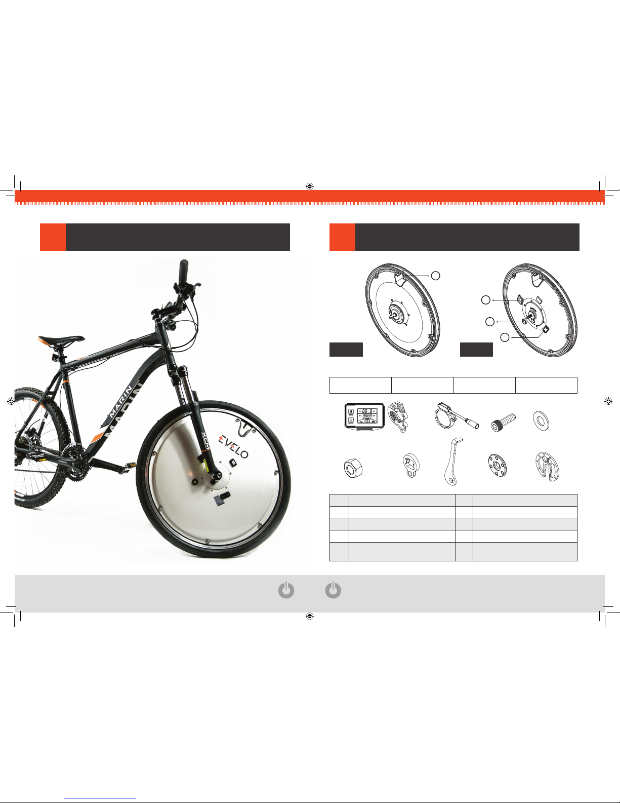
2.1
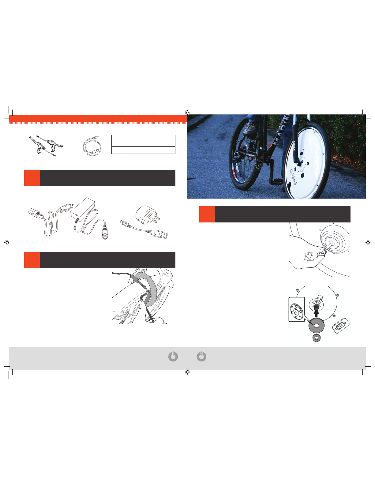
A Omni Wheel G Axle Nut
B Console and Bracket H Torque Washer
C Pedal Assist Sensor (PAS) I Torque Arm
E Hex Bolt (M4xP0.7x10) J Magnetic Sensor Disc
F
Washer (Adjust the quantity of washers
used based on your front fork)
K PAS Magnetic Disc
1. Valve Opening 2. Charging Port 3. Power Switch 4. Service Port
3
2
4
1
A Side B Side
INSTALLATION
A
A.
H. I. J.
K.
B.
C. E. F.
G.
X10
X2
B C E F
G H I J
K
INSTALLATION
2
Page 5
OMNI.EVELO.COM
8
OMNI.EVELO.COM
9
L
Brake Levers
(with Electronic Cut-o Switch)
N Connecting Wire
Omni Wheel Charger Console Charger
ACCESSORIES
2.2
INSTALLATION
L. M. N. O.
L N
REMOVAL OF FRONT WHEEL
2.3
INSTALLATION
STEP
Remov e the ex isting front w heel f rom
bicyc le. If necess ary for cleara nce,
release front brake caliper as shown.
OMNI WHEEL
2.4
INSTALLATION
STEP - Side A
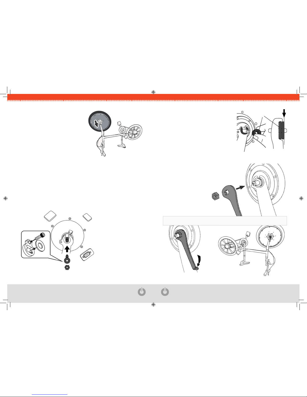
Insert 1 to 4 Washers (F) onto the axl e on
side A (the number of was hers n eeded
depe nds upo n the front fo rk spec ificat ion).
Note: the O mni Wh eel is design ed for standar d
100mm front fork spacing, +/- 3mm.
Note : The O mni Wh eel has two s ides – A and B.
Choose the correct side for each step as indicated.
STEP - Side B
Insert the Magnetic Sensor Disc (J) into the
axle of sid e B, t urning the ma gnet si de to face
the wheel cover/axle.
Place 1 to 4 Washers (F) onto t he dis c (the
numb er of wa shers needed depend s on t he
fork width).
*
OPTIONAL
Optional : If your bicycle is equipped with disc brakes, please contact us at [email protected]
or 877 991 7272 to purchase an optional disc brake rotor compatible with the Omni Wheel.
J
F
Page 6
OMNI.EVELO.COM
10
OMNI.EVELO.COM
11
STEP
Plac e the b ike ups ide-dow n. Ori ent the
Omni Wheel so tha t Side B is o n the
same side a s the bicycle chain .
Note: Side B has the various electronic ports.
Lower the Om ni Whee l into the for k
dropouts.
STEP - Side B
Insert Hex Bolt (E) through Torque Washer (H). Add 1 to 3 Washers (F) onto the
axle and install the Torque Washer (H) with t he scre w head facing the wh eel.
Tighten the Axle Nut (G).
Note: the HEAD of Hex Bolt (E) goes toward the wheel.
If a recess exists on the outsid e of yo ur fork dropou t, use the p rovided washers to
fill the recess to provide a smooth, level surface for the Torque Washer (H).
Note: the Torque Arm (I) must be in contact with the fork in the position shown below.
STEP - Side A
Install 2 to 3 Washers (F) onto t he axle
of Si de A. Add eno ugh wa shers s o that
the last was her ad ded sta nds ab ove the
surface of the fork (as in drawing A).
STEP
- Side A
Install the Torque Arm (I) paral lel to the fo rk
and tighten the Axle Nut (G).
G
I
G
F
E
H
A Side
A
F
Page 7
OMNI.EVELO.COM
12
OMNI.EVELO.COM
13
C-1
PAS SPEED SENSOR
2.5
INSTALLATION
STEP
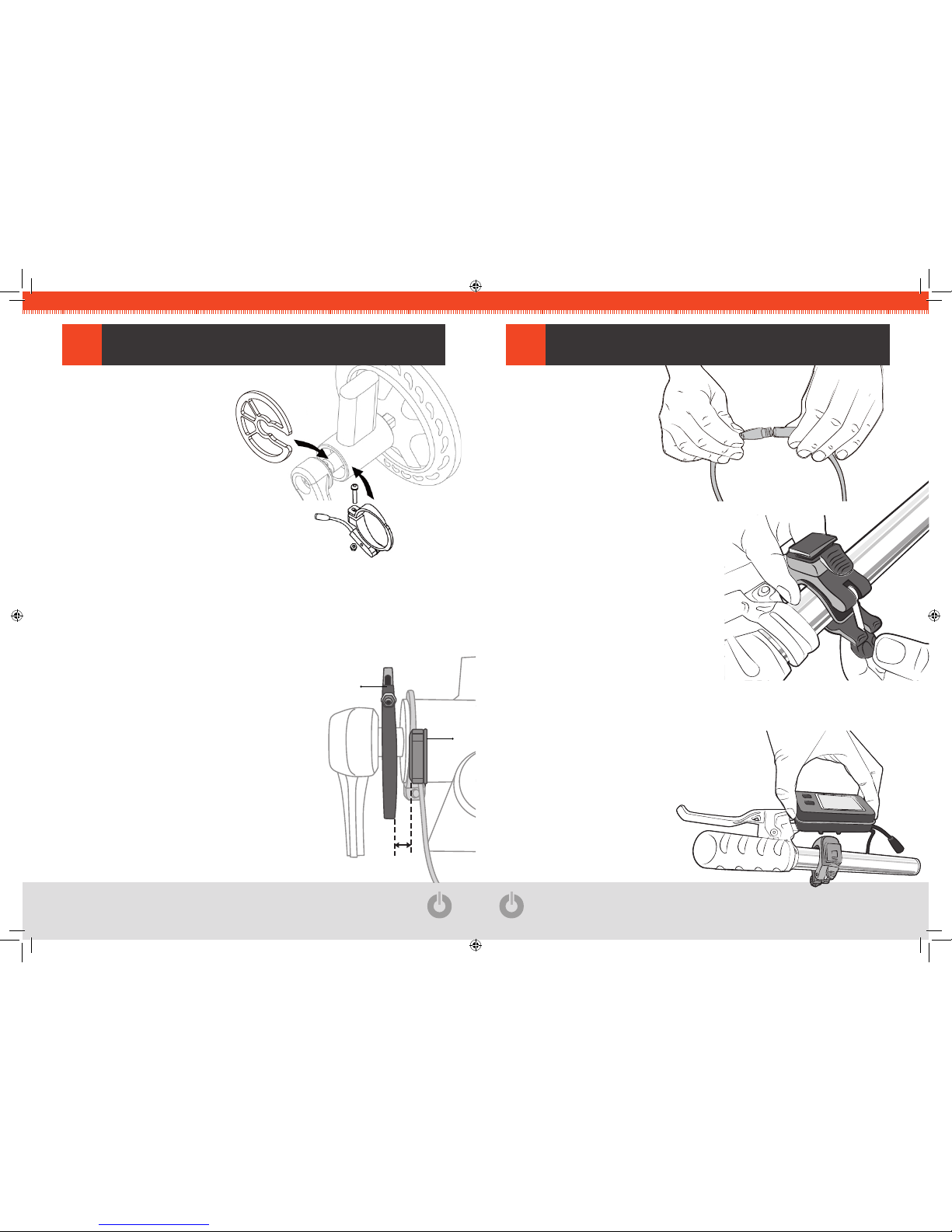
First loose n/remove t he sc rew
holding the PAS Sen sor (C)
toget her, and then w rap it around
the bottom b racket tu be on the bi ke
frame. Repla ce/retight en the screw
to secure it in place.
Do n ot over-t ighten the sc rew or you
may break the PAS Sensor (C).
STEP
Insert the PAS Magnetic Disc (K) onto th e crank axle. The di rection of the arrow
on the magnetic disc should be consistent with the forward-pedaling direction.
Note: the arrow on the disc should point toward the rear of the bike when it is upside down.
* Your Omni Wheel may co ntain a n alter native,
snap -on vers ion of the PAS Ma gnetic Sensor Disc.
If t hat is t he cas e, simp ly sli de it o nto the crank
axle. This version does n ot come with o r requir e a
bolt to be tightened.
Make sure the distance between the PAS Senso r
(C) and the PAS Magnetic Sensor Disc (K) is
between 2-3mm before tightening it in place.
Do not over-tighten either the PAS Sensor (C) or
the PAS Magnetic Disc (K)!
2-3mm
K
C
K
C
CONSOLE
2.6
INSTALLATION
STEP
Conn ect one end of the
Connecting Wire (N) to
the PAS Sensor (C).
Make s ure tha t the a rrows
on the plugs align.
STEP
Wrap the Consol e Bracket (B)
aroun d the h andleb ars an d tight en,
maki ng sure that t he cons ole
release tab faces toward the rider.
STEP
Snap the Console (B) onto the b racket,
working from the top down.
Connect the console cable to the Conn ecting
Wire (N) (one end of which was att ached t o the
PAS Sensor(C) in Step 1).
Make sure that the arrows on the plugs align.
Page 8
OMNI.EVELO.COM
14
OMNI.EVELO.COM
15
BRAKE LEVERS
2.7
INSTALLATION
WITH ELECTRONIC
CuT-OFF SWITCH
STEP
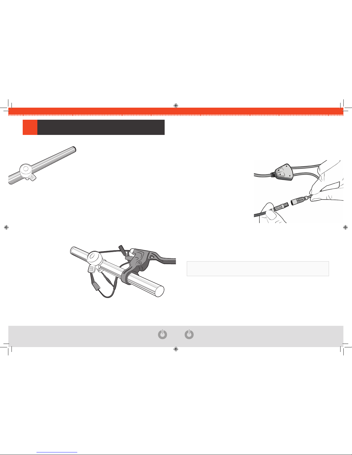
Remov e the r ight-si de han dlebar grip, g ear
shift er, and t he ori ginal brake leve r from your
bicycle.
Note: Compressed air or WD-40 are helpful if the
grip is stuck in place.
STEP
Install the new Brake Lever with Electronic Cut-Off Switch (L) and connect the
brake line.
Make sure your brakes are properly installed and adjusted before riding.
STEP
Install the gear shifter and rightside handlebar grip back on.
Note: Hairspray can help to slide
your grip back into place.
*
OPTIONAL
STEP
Adjust the new brake lever to make sure it is installed at a comfortable angle.
Chec k that all of the wi res are reconne cted an d test the bra ke by en gaging it
severa l time s. Make sure th e brake engage s and d isenga ges ea sily a nd smoo thly
using the new brake lever.
STEP
Conn ect the new br ake lever
to th e cons ole, c hecking to
make s ure tha t the a rrows o n
the plugs a re alig ned.
Secu re all o f the wires to the
bicyc le fram e with zip ti es,
leavi ng eno ugh sla ck for
turning and maneuvering.
If replacing your left-side brake lever with the second Brake Lever wi th Elec tronic
Cut-Off Switch (L), follow the steps above for the left brake lever.
Important: Do not forget to reattach the front brake caliper if you have removed it when
initially installing the Omni Wheel.
Page 9
OMNI.EVELO.COM
16
OMNI.EVELO.COM
17
TuRNING ON THE OMNI WHEEL2.8
INSTALLATION
To turn on the EVELO Omni Wheel, perform the following steps:
Make sure that both the Omni Wheel and the Console are fully charged.1.
Switc h on t he Omni Wheel by pres sing t he powe r butto n. Wait 2- 3 seco nds 2.
and then switch on the Console by pressing the power button on the display.
Note: Always power on the Omni Wheel before turning on the Wireless Console. Once a
signal strength indicator appears on the screen, the Omni Wheel and the Wireless Console
are connected. Turning on the Console before the Omni Wheel will result in an error message
(E-0).
The EVELO Omn i Whee l’s integ rated en ergy-sav ing tec hnolog y will automa ticall y
power off th e system if th e bike s tops fo r more than 15 minut es.
To re-star t the system, turn o ff both the Om ni Whe el and the Wi reless Consol e.
Wait 3 to 5 seconds, and then turn both on again.
CONSOLE OPERATING INSTRuCTIONS
3
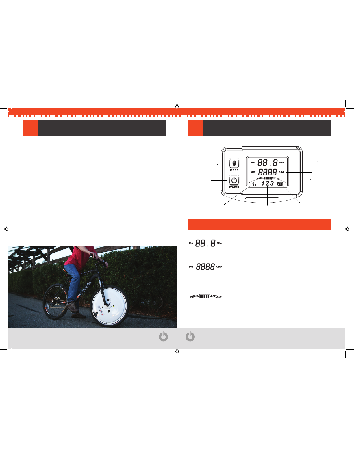
DATA READOuTS3.1
Level of assistance
is se lected by usi ng
the mode button
Power On / Off
Battery life
indicator
(of Omni Wheel)
Speed
Odometer
Wireless signal strength
Battery life indicator
(of Console)
PAS (Pedal Assist) Level
Speed
The speed i s disp layed i n kilom eters p er hou r (Kph ) or mi les
per hour. The default setting is in Kph.
Odometer (DIS/ODO)
Dista nce is displa yed in kilome ters or miles . When the
maxi mum dis tance o f 9999 units is reac hed, t he numb er
reverts back to 0.
Battery Life Indicator for the Omni Wheel
5 ba rs indi cate a full c harge. When th e level drops to 2 b ars
or b elow, the indica tor wi ll begi n to f lash, l etting the ri der
know that the Omni Wheel needs to be recharged soon.
Page 10

OMNI.EVELO.COM
18
OMNI.EVELO.COM
19
Note: It is normal for this indicator to flicker and drop quickly in high
power draw si tuation s such as rid ing up a steep hill or agai nst a
headw ind. T he read ings wi ll retu rn to normal as soon as th e power
draw drops to normal levels.
Battery Life Indicator for the Wireless Console
5 ba rs indi cate a full c harge. When th e level drops to 2 b ars
or b elow, the indica tor wi ll begi n to f lash, l etting the ri der
know that the Console needs to be recharged soon.
Wireless Signal Strength Indicator
The Wireless Conso le and the O mni Whe el use 2.4G
wirel ess tec hnolog y to co mmunic ate wit h each other — 4
bars indic ate a f ull-stre ngth s ignal a nd 0 b ars in dicate no
sign al. A ze ro bar reading may me an tha t the O mni Wh eel is
off and needs to be turned on.
Power Button
Press the button to turn the Wireless Console on or off.
Mode Button
With the Wi reless Consol e on, press t he Mode button to
cycle throug h the levels of power assist from 1 throug h 3.
Level 4 is p edal-on ly mod e with no ass ist, b ut leav es the
console on to display speed and record distance travelled.
Pedal ing th e bike a ctivate s the m otor wh en a p ower-ass ist
level is selected.
ADDITIONAL CONSOLE FuNCTIONALITY3.2
Braking
The Braking Indica tor Li ght wil l begin to fl icker wh en the power
brakes are applied.
Wheel Size Set Up
Press and ho ld the Mode button for 10 second s to en ter the wheel
size selection mode.
Once the co rrect s ize is select ed, pre ss the Power bu tton to save
the selection and return to stand-by mode.
Page 11
OMNI.EVELO.COM
20
OMNI.EVELO.COM
21
CHARGING
4
CHARGING THE CONSOLE
4.1
Before first use, charge the Console for 12 hours.•
It takes 3-4 hours to charge the Console completely.•
The use of non-OE M and/or n on-EVE LO-approve d charg ers is prohib ited an d •
will void the warranty.
The optimal temperature for charging the Console is 32°F-100°F.•
It i s neces sary t o recha rge the Conso le imme diately after each u se, and once •
every 14 days when not in use for extended periods of time.
Before first use, charge the Omni Wheel for 12 hours.•
It takes 4-6 hours to charge the Omni Wheel completely.•
The use of non-OE M and/or n on-EVE LO-approve d charg ers is prohib ited an d •
will void the warranty.
The optimal charging temperature for the Omni Wheel is 32°F-100°F.•
It i s neces sary t o recha rge the Omni W heel i mmediat ely aft er each use, and •
once a month when not in use for extended periods of time.
CHARGING THE EVELO OMNI WHEEL
4.2
CHARGER LED COLOR CHART
4.3
Green LED
Standby Mode
Orange LED
Charging
Green LED
Fully Charged
It i s impor tant th at you clean the EV ELO Omni Wheel on a re gular basis a nd keep it
away from corrosive materials such as salt.
Do n ot poli sh or d rill t he whe el surf ace. Eve n a sma ll ope ning m ay caus e leak s •
which can damage the electronics inside of the wheel.
Press ure wash ing of the wh eel is strict ly proh ibited and wi ll void the wa rranty. •
To clean the Omni Wheel, just use a damp cloth.
Do n ot leave the O mni Whe el una ttended outsid e or ex posed to the sun or rain •
for extended periods of time.
Infla ting T ire – To inf late yo ur EVELO Omni W heel T ire, use the ext ension •
elbow provid ed. Gen tly th read the elbow onto t he Schra der va lve, the n firm ly
tight en to p revent l eaks wh ile in flating . Once the exte nsion is in p lace, inflate
the tire as usual. Be sure to remove the elbow extension prior to riding.
MAINTENANCE & REPAIR
5
Page 12
Page 13
 Loading...