

Eve Audio ThunderStorm TS107, ThunderStorm TS110, ThunderStorm TS108, ThunderStorm TS112 Product Manual
EVE AUDIO PRODUCT MANUAL
TS108
TS110
TS112
TS107
AUG 2013

TS108
TS110
TS112
TS107
EVE Audio product manual
2 3
SAFETY INSTRUCTIONS
To avoid the risk of electrical shock, do not attempt to open the unit.
There are no user-serviceable parts inside. Do not attempt to service the
equipment yourself. In case of problems, please contact your local dealer
or distributor.
This unit should be connected to a grounded power outlet. If you use
extension cords and power distributors they should be grounded as well.
Verify that the specied operating voltage on the rear side matches the
local mains voltage. If these values do not match you will have to adjust
the loudspeaker setting appropriately and change the fuse type.
Use only the fuse types specied on the rear side of the unit. Never bypass
the fuse.
Make sure that no liquids wet the inside of the cabinet. Never spray, pour
or spill liquids directly onto the unit.
Do not use a wet cloth nor ammable or acid chemicals for cleaning.
Do not touch the diaphragms of the loudspeaker.
Make sure there is enough air ow behind the loudspeaker to maintain the
electronic components cool.
Do not expose this product to extreme temperatures.
The diaphragms build up a magnetic eld around the loudspeaker.
High sound pressure levels can damage your hearing permanently! Avoid
standing close to loudspeakers producing high sound pressure levels.
TABLE OF CONTENT
1. INTRODUCTION ............................................................................4
2. QUICK START .................................................................................5
2.1. First Steps .............................................................................................................................5
2.2. Subwoofer Connection ...................................................................................................5
2.3. Powering On .......................................................................................................................5
3. OPERATION ...................................................................................6
3.1. First Steps .............................................................................................................................6
3.2. Operating Modes ..............................................................................................................7
3.3. Powering on/o: Standby Mode .................................................................................7
3.4. Volume Mode .....................................................................................................................7
3.5. Settings Menu ....................................................................................................................9
3.6. Filter .......................................................................................................................................9
3.7. Sat. Filter ...............................................................................................................................9
3.8. Sub Filter ........................................................................................................................... 10
3.9. Sub Phase .......................................................................................................................... 10
3.10. LED Mode .......................................................................................................................... 10
3.11. Saving Your Settings ..................................................................................................... 11
3.12. Remote Control ............................................................................................................... 11
3.13. Power Switch ................................................................................................................... 12
3.14. DIP Switches ..................................................................................................................... 12
3.15. Mains Voltage Selector ................................................................................................. 13
3.16. Power Connector (IEC) ................................................................................................. 13
4. POSITIONING ..............................................................................14
4.1. Subwoofer Positioning ................................................................................................. 14
4.2. Height and Distance ..................................................................................................... 14
4.3. Stereo Setup + Subwoofer (2.1) ................................................................................ 15
4.4. Multichannel Setup (5.1) ............................................................................................. 16
4.5. Room Acoustics .............................................................................................................. 17
5. TECHNICAL SPECIFICATIONS .....................................................18
6. COMPLIANCE ...............................................................................19
7. WARRANTY ..................................................................................20
!
!
!
!
!

TS108
TS110
TS112
TS107
EVE Audio product manual
Powering On
4 5
INTRODUCTION
QUICK START
1. INTRODUCTION
Thank you for your time and interest in the EVE Audio product range.
EVE Audio is a loudspeaker manufacturer based in Berlin, Germany, that
specializes in the development and design of unique studio monitors.
The use of rst-class components is our highest priority because we rmly
believe this is the only way to manufacture rst-class products.
You have chosen a subwoofer from our ThunderStorm series. All four
models— TS107, TS108, TS110 and TS112— make use of passive radiators
instead of a bass reex port. This allows for a lower tuning of the subwoofer
and avoids the emergence of hum, which is unavoidable when applying
the bass reex port design. The passive radiator is on the bottom side of
the subwoofer.
The subwoofers of the ThunderStorm series are the ideal extension for the
two, three and four-way systems of the EVE Audio lverCone series. They
can be easily integrated in any situation thanks to their ThunderStorm
Chassis (6,5”, 8”, 10” and 12”), PWM ampliers (100, 150, 250 and 400 Watt),
accurate DSP technology and IR remote control.
We wish you a lot of fun with your EVE Audio subwoofer. If you have any
questions regarding our products, do not hesitate to contact your nearest
dealer or get directly in touch with us... We will be more than happy to help
you out!
All the best from Berlin.
The EVE Audio Team
2. QUICK START
If you already have experience with studio subwoofers, the Quick Start
guide ought to be more than enough to get you started.
For unexperienced users we recommend reading the whole user’s manual
in order to prevent any misuse.
2.1. First Steps
Check the package components (loudspeaker, remote control + batteries,
user’s manual, power cord).
Check the voltage setting (see “Mains Voltage Selector”).
Check the setting of the DIP Switches (variable).
2.2. Subwoofer Connection
Connect the two inputs on the rear side (L In + R In) to the left and right XLR
outputs of a playback source, for instance, an audio interface. The output
level should be as low as possible.
Connect the two outputs on the rear side (L Out + R Out) to the
corresponding XLR inputs of your studio’s left and right satellites. All
output levels should be as low as possible.
2.3. Powering On
Engage the Power switch on the rear side of the subwoofer to turn it on
or o.
The LEDs around the System Volume control on the front panel will light
up clockwise. If the LED on the right end is dimly lit, this indicates that the
subwoofer is in Standby mode. Press the System Volume control to turn
the subwoofer on. If you turn the System Volume control counter clockwise
until the LED on the left end lights up dimly the subwoofer will be muted.
Increase the output level on the source device until the LED ring starts to
blink, then reduce the output level a bit. The maximum operating level
for the input (i.e. the analog to digital converter) is now set optimally. To
set the desired listening volume use the System Volume control on the
subwoofer. The LED ring indicates the volume setting. If the LED ring starts
to blink, reduce the output level on the signal source.
TS108
TS110
TS112
TS107
EVE Audio product manual
First Steps Volume Mode
6 7
OPERATION
OPERATION
3. OPERATION
3.1. First Steps
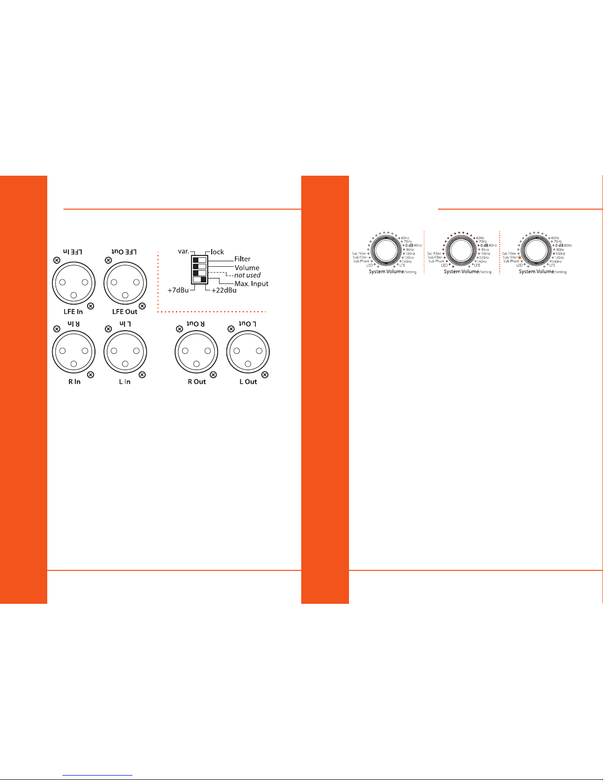
Rear Connections & DIP Switches
Check the package components (loudspeaker, remote control + batteries,
user’s manual, power cord).
Check the voltage setting (see “Mains Voltage Selector”).
Check the setting of the DIP Switches (variable).
Connections: there are XLR input and output connectors on the rear side
that allow the connection of balanced and unbalanced devices (signal
sources, active monitors, etc.).
• Balanced XLR pin assignment XLR: 1= Shield, 2= hot (+), 3= cold(-).
• Unbalanced XLR pin assignment XLR: 1+3= Shield, 2= Signal.
Depending on the setting of the Max. Input DIP switch on the rear panel,
the maximum level of the source signal should not exceed +7 dBu or +22
dBu (see Max. Input). If the input is overloaded the LED ring will start
blinking.
3.2. Operating Modes
Standby mode | Volume mode (-10dB) | Settings menu (Sub Filter @ 100 Hz)
3.3. Powering on/off: Standby Mode
Press and hold the System Volume control three seconds in order to put the
subwoofer in Standby mode. The total volume (subwoofer + satellites) will
decrease gradually while the LED ring lights up once around the System
Volume control. Afterwards, the LED on the right end will remain dimly lit
and the power consumption is reduced to 1 watt.
! To exit the Standby mode press briey the System Volume control once
again. The level will increase gradually until it reaches the previously
selected volume.
3.4. Volume Mode
• Level Adjustment
The maximum input level for balanced and unbalanced signals is +7dBu
or +22 dBu, depending on the position of the Max. Input switch on the rear
panel (see DIP Switches). Higher levels at the input produce distortion due
to the overloading of the analog to digital converter.
Given that some professional studio devices can produce in excess of
+22 dBu, the LED ring will start blinking whenever the AD converter is
overloading. Generally speaking, the +7dBu setting ought to be suitable. If
that is the case, the output level of the source should be reduced.
• Total Volume Adjustment
Turn the System Volume control to adjust the total volume (subwoofer
+ satellites). Depending on the LED mode selected (see LED mode), the
volume will be displayed as a dim/bright circle or as a dim/bright point.
• Subwoofer Volume Adjustment
Turn the Subwoofer Volume control to adjust the volume of the subwoofer
independently from the satellites. This allows you to strike the right
balance between subwoofer and satellites. The LED ring indicates the
volume setting.
 Loading...